

Tecfluid FLOMAT Series, Converter XL1, FLOMAT-XL Instruction Manual
R-MI-FAXL1 Rev.: 0 english version
Series FLOMAT
Sensor FLOMAT-XL + Converter XL1
Instructions manual
The art of measuring

2
Thank you for choosing a product from Tecfluid S.A.
This instruction manual allows the installation, configuration,
programming and maintenance. It is recommended to read it before
using the equipment.
This document shall not be copied or disclosed in whole or in any
part by any means, without the written permission of Tecfluid S.A.
Tecfluid S.A. reserve the right to make changes as deemed
necessary at any time and without notice, in order to improve the
quality and safety, with no obligation to update this manual.
Make sure this manual goes to the end user.
Keep this manual in a place where you can find it when you need
it.
In case of loss, ask for a new manual or download it directly from
our website www.tecfluid.com Downloads section.
Any deviation from the procedures described in this instruction
manual, may cause user safety risks, damage of the unit or cause
errors in the equipment performance.
Do not modify the equipment without permission. Tecfluid S.A. are
not responsible for any problems caused by a change not
allowed. If you need to modify the equipment for any reason,
please contact us in advance.
PREFACE
WARNINGS

3
TABLE OF CONTENTS
SERIES FLOMAT
1 INTRODUCTION ........................................................................... 5
2 RECEPTION ................................................................................. 6
2.1 Unpacking .......................................................................... 6
2.2 Storage temperatures ......................................................... 6
3 HANDLING ................................................................................... 6
4 INSTALLATION ............................................................................. 6
4.1 Straight pipe sections ......................................................... 6
4.1.1 Mixtures ................................................................ 8
4.2 Sensor position .................................................................. 8
4.3 Valves ............................................................................... 8
4.4 Pumps ................................................................................ 9
4.5 Aeration ............................................................................. 9
4.6 Vibrations ........................................................................... 10
4.7 Magnetic fields .................................................................. 10
4.8 Temperature ...................................................................... 10
5 MOUNTING .................................................................................. 11
5.1 Pipe adaptor mounting ....................................................... 11
5.2 Sensor mounting ................................................................ 13
5.3 Tightening torque ................................................................ 13
5.4 Electronic converter connection .......................................... 13
5.5 Electronic converter programming ........................................ 13
6 ELECTRICAL CONNECTION ........................................................... 14
6.1 Power supply wiring ............................................................ 14
6.2 Analog output wiring ........................................................... 15
6.3 Digital output wiring ............................................................ 16
7 ASSOCIATED SOFTWARE WINSMETER XL1 ................................. 18
7.1 USB cable connection and software installation ................... 18
7.2 Port connection ................................................................... 19

4
7.3 Password ........................................................................... 20
7.4 Access to “Installation” ....................................................... 24
7.4.1 Sensor .................................................................. 24
7.4.2 Power supply ......................................................... 24
7.5 Access to “Programming” ................................................... 25
7.5.1 Current loop .......................................................... 25
7.5.2 Units ....................................................................... 26
7.5.3 Digital output ......................................................... 26
7.5.4 Current loop calibration .......................................... 26
7.6 Visualization ....................................................................... 27
7.7 Zero flow drift adjustment .................................................... 27
7.8 Datalogger ......................................................................... 28
7.9 Firmware updates ............................................................... 29
7.10 Configuration file ................................................................. 30
8 MAINTENANCE ............................................................................ 31
9 TECHNICAL CHARACTERISTICS ................................................... 32
10 SAFETY INSTRUCTIONS ............................................................... 33
10.1 Pressure equipment directive .............................................. 33
10.2 Certificate of conformity TR CU (EAC marking) ..................... 33
11 DIMENSIONS ............................................................................... 34
12 TROUBLESHOOTING .................................................................... 37
ANNEX Flow rate diagram ................................................................... 38
5
1 INTRODUCTION
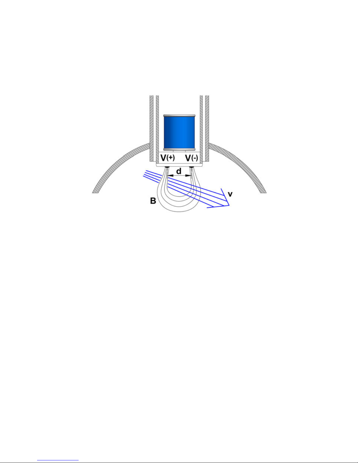
The FLOMAT electromagnetic flowmeters are based on Faraday’s induction law.
When an electrically conductive liquid flows through a magnetic field, perpendicular to the
flow direction, it induces a voltage V proportional to the liquid velocity.
Two electrodes in contact with the liquid and positioned perpendicularly to the magnetic
field, sense this voltage V.
The electronic converter is based on the most advanced technology in digital signal
processing, in order to obtain accurate and reliable measurements.
The device provides the following features:
Coil excitation by means of pulsed signal to obtain a negligible zero offset.
Pulse and current output proportional to the flow rate and user programmable.
V = B·v·d
Where:
V = Measured voltage in the electrodes
B = Magnetic field
v = Liquid velocity
d = Distance between electrodes

6
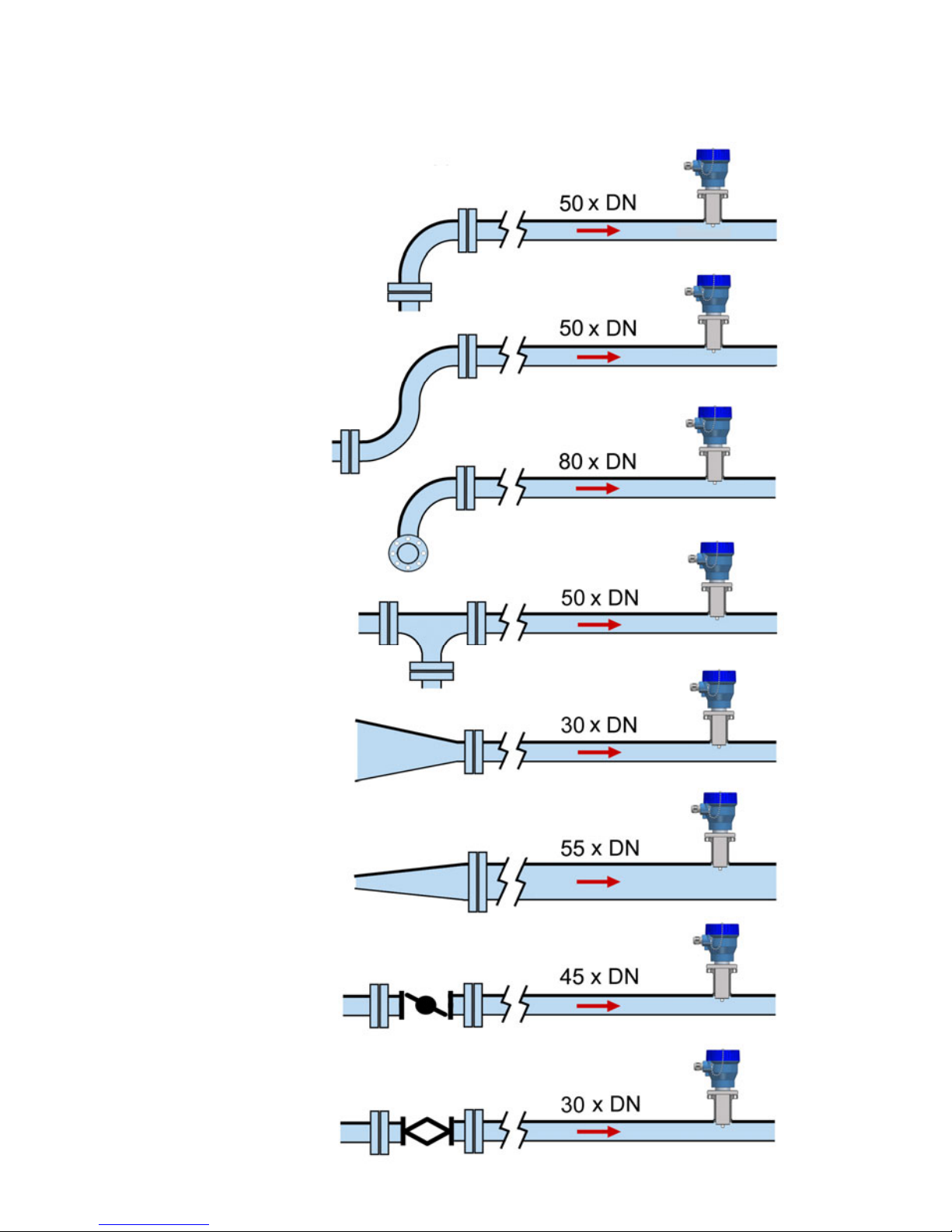
4.1 Straight pipe sections
The point where the FLOMAT sensor will be installed must be a straight pipe section,
separated from elements that can disturb the flow profile, such as elbows, diameter
changes, etc. Depending on the element the minimum necessary distances upstream from
the sensor are shown on the next page (BS 1042-2.2:1983 standard):
2 RECEPTION
The FLOMAT electromagnetic flowmeters with XL1 converter are supplied conveniently
packaged for transportation together with their instruction manual for installation and
operation.
All the flowmeters have been verified in our calibration rigs to obtain the gain factor for each
sensor.
2.1 Unpacking
Unpack the instrument carefully, removing any remains of the packing.
2.2 Storage temperatures
-20ºC ...... +60ºC
3 HANDLING
It should always be done with care and without knocks.
4 INSTALLATION
This should be made in a straight pipe run that guarantees that the pipe is always completely
full.
Avoid high points of the pipes where air pockets usually form, or pipes with downwards
flow where vacuums can occur.
Partially full pipes can involve important reading errors.
Flow rate measurement with open discharge makes it necessary to install the flowmeter in a
pipe section with a siphon which avoids stagnation of air in the sensor.
7
Disturbing element
upstream the
sensor
Minimum distance between
the sensor and the element
Several 90º
coplanar bends
Fully opened plug
valve
Fully opened
butterfly valve
90º elbow
Several 90º non-
coplanar bends
T accessory
Total angle
convergent 18 to 36°
Total angle
divergent 14 to 28°
8
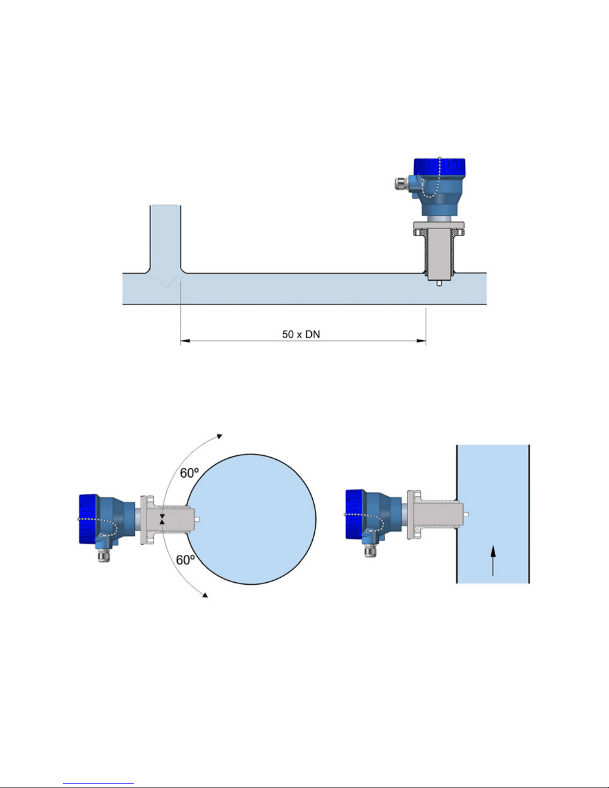
4.2 Sensor position
The optimum position to install the sensor is with the electrodes in the side of the pipe. This
way, air pockets at the top of the pipe are avoided.
Downstream, the minimum recommended distance to a disturbing element is 5 x DN.
4.1.1 Mixtures
If liquids of different conductivities are mixed it is necessary to install the sensor a minimum
of 50 x DN from the point of mixture in order to obtain a uniform conductivity of the liquid
and stabilize the readings.
If this distance is shorter, readings may be unstable.
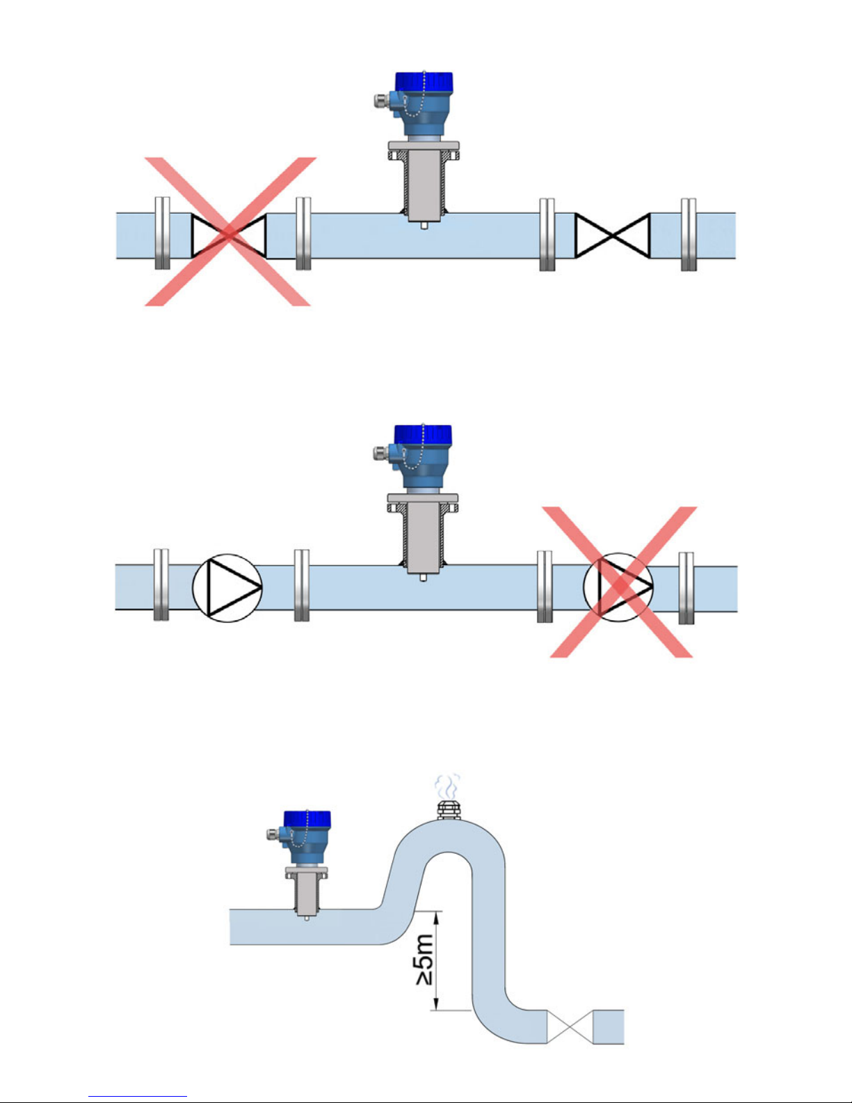
4.3 Valves
Control valves or shut-off valves should always be installed downstream from the sensor to
assure that the pipe is always full of liquid.
9
4.5 Aeration
If there is a point where the difference in level is higher than 5 m an air inlet valve should be
installed after the sensor to avoid a vacuum effect that could damage the sensor.
4.4 Pumps
Pumps should be mounted upstream from the sensor to avoid the suction of the pump
(vacuum).
10
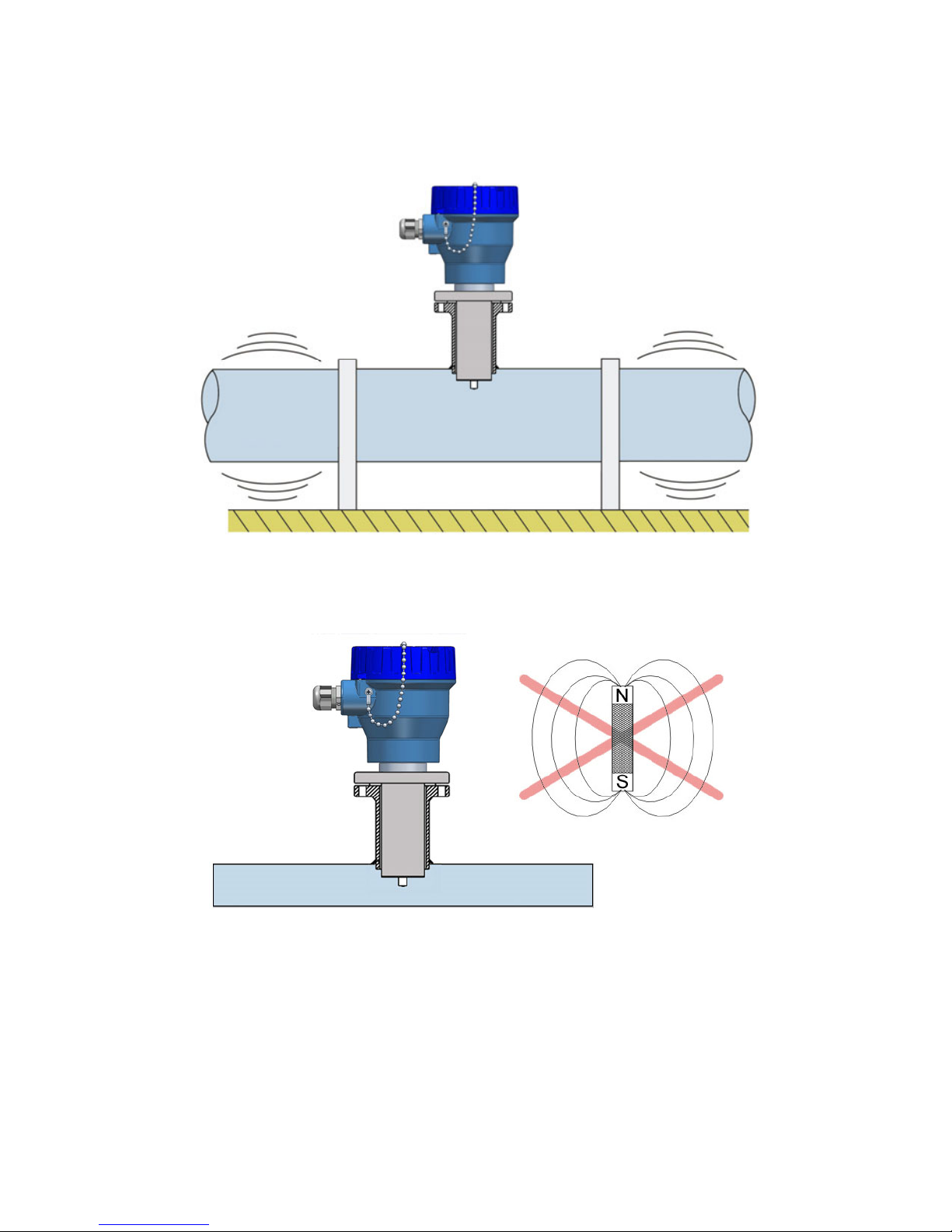
4.6 Vibrations
Vibrations of the pipes should be avoided by anchoring the pipe before and after the sensor.
The vibration level should be less than 2.2 g in the range of 20 -150 Hz according to IEC 068
-2-34.
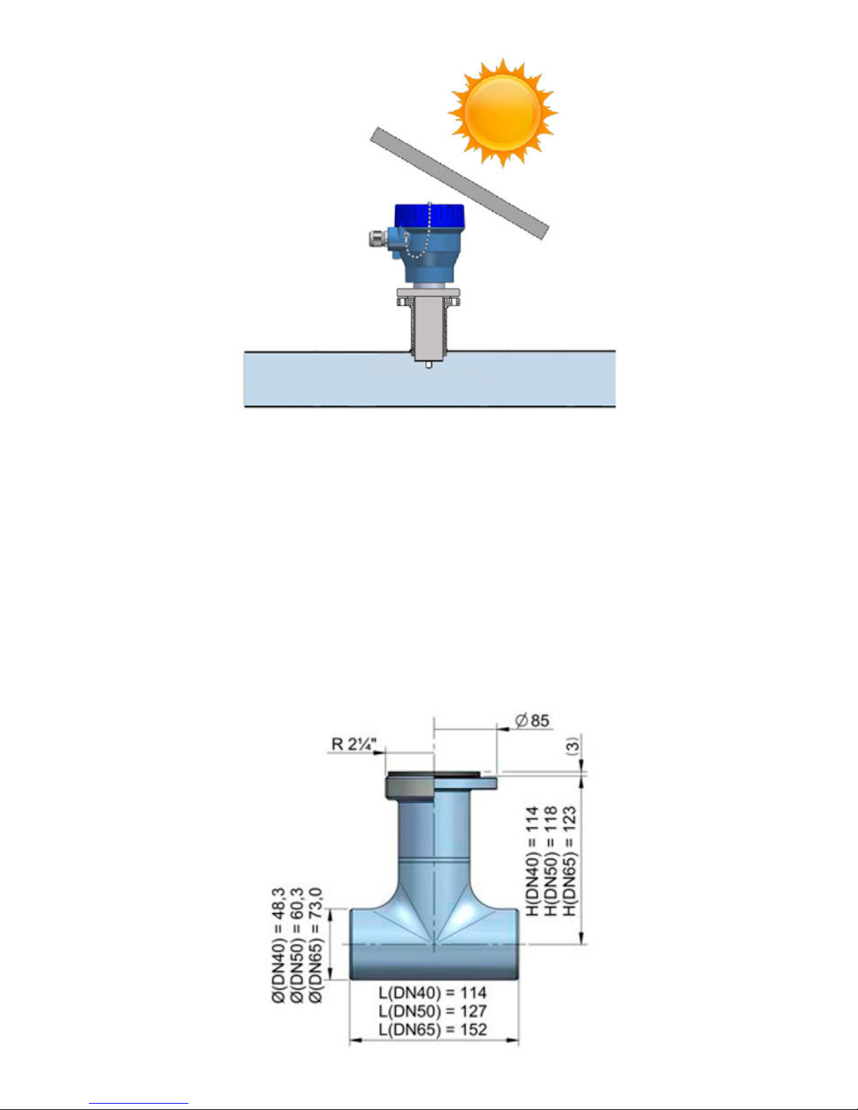
4.8 Temperature
In open air installations it is recommended to install a protection to avoid direct sun light on
the flowmeter.
4.7 Magnetic fields
Strong magnetic fields close to the sensor should be avoided.
11
With thermally insulated pipes DO NOT insulate the sensor. High temperatures can damage
it.
The maximum liquid temperatures are shown on page 32.
5 MOUNTING
5.1 Pipe adaptor mounting
The sensor is normally supplied mounted in its pipe adaptor. Before welding the adaptor to
the pipe, the sensor must be removed to avoid irreparable damage due to excessive
temperatures.
There are two basic types of pipe adaptors: with threaded or with flanged connection.
For the smallest pipe diameters (DN40, 50 & 65) the pipe adaptor is supplied welded to a
short length of pipe with a “T” form. For this type just couple it to the pipe by welding or
gluing in the case of PVC, PP, PE or other plastics.

12
For DN80 and bigger, there are three lengths for each of the two types of fittings.
The process of putting the pipe adaptor in should be done accurately. The distance (H) (see
drawings on next page) which is what the pipe adaptor should protrude above the surface of
the pipe is important.
As shown in the table on the next page, to know the distance, the thickness of the pipe s
must be known.
In order to make the positioning of the pipe adaptor in the pipe easier, there is a label on one
of its sides with markings indicating the position of the internal pipe diameter for each DN.
Cut this label above the line corresponding to the DN of the pipe, at a distance equal to the
pipe thickness. Peel off the bottom part of the label. Once the pipe adaptor is placed into its
final position, where the label was cut must coincide with the outer diameter of the pipe.
This ensures that the measuring electrodes penetrate far enough in the area of flow profile
that will allow an accurate measurement.
DN C (mm)
Insert pipe adaptor
L (mm) H (mm)
80 10
93
88-s
100 12,5 85,5-s
125 15,5 82,5-s
150 19 79-s
200 25 73-s
250 31 67-s
300 37,5 60,5-s
350 44 54-s
400 50 48-s
500 62,5
145
140,5-s
600 75 128-s
700 87,5 115,5-s
800 100 103-s
900 112,5 90,5-s
1000 125 78-s
1200 150 203-s
1400 175 178-s
1600 200 153-s
1800 225 128-s
2000 250 103-s
205
 Loading...