


» D00414800A
MD-801R@#/ MD-801P@#
MD Recorder/Player
OWNER’S MANUAL
ÜREMOVE COVER (OR BACK). NO USER-SERVICEABLE PARTS INSIDE. REFER SERVICING TO QUALIFIED SERVICE PERSONNEL.CAUTION: TO REDUCE THE RISK OF ELECTRIC SHOCK, DO NOT
ÿThe lightning flash with arrowhead symbol, within an equilateral triangle, is intended to alert the user to the presence of uninsulated “dangerous voltage” within the product’s enclosure that may be of sufficient magnitude to constitute a risk of electric shock to persons..
Ÿence of important operating and maintenance (servicing) instructions in the literature accompanying the appliance.The exclamation point within an equilateral triangle is intended to alert the user to the pres-
This appliance has a serial number located on the rear panel. Please record the model number and serial number and retain them for your records.
Model number Serial number
WARNING: TO PREVENT FIRE OR SHOCK HAZARD, DO NOT EXPOSE THIS APPLIANCE TO RAIN OR MOISTURE.

Important Safety Precautions
IMPORTANT (for U.K. Customers)
DO NOT cut off the mains plug from this equipment.
If the plug fitted is not suitable for the power points in your home or the cable is too short to reach a power point, then obtain an appropriate safety approved extension lead or consult your dealer.
If nonetheless the mains plug is cut off, remove the fuse and dispose of the plug immediately, to avoid
a possible shock hazard by inadvertent connection to the mains supply.
If this product is not provided with a mains plug, or one has to be fitted, then follow the instructions given below:
IMPORTANT: The wires in this mains lead are coloured in accordance with the following code:
GREEN-AND-YELLOW : EARTH
BLUE |
: NEUTRAL |
BROWN |
: LIVE |
WARNING: This apparatus must be earthed.
As the colours of the wires in the mains lead of this apparatus may not correspond with the coloured markings identifying the terminals in your plug proceed as follows:
The wire which is coloured GREEN-and-YELLOW must be connected to the terminal in the plug which is marked by the letter E or by the safety earth symbol ç or coloured GREEN or GREEN-and-YELLOW.
The wire which is coloured BLUE must be connected to the terminal which is marked with the letter N or coloured BLACK.
The wire which is coloured BROWN must be connected to the terminal which is marked with the letter L or coloured RED.
When replacing the fuse only a correctly rated approved type should be used and be sure to re-fit the fuse cover.
IF IN DOUBT — CONSULT A COMPETENT ELECTRICIAN.
TO THE USER
This equipment has been tested and found to comply with the limits for a Class A digital device, pursuant to Part 15 of the FCC Rules. These limits are designed to provide reasonable protection against harmful interference when the equipment is operated in a commercial environment. This equipment generates, uses, and can radiate radio frequency energy and, if not installed and used in accordance with the instruction manual, may cause harmful interference to radio communications.
Operation of this equipment in a residental area is likely to cause harmful interference in which case the user will be required to correct the interference at his own expense.
CAUTION
Changes or modifications to this equipment not expressly approved by TEAC CORPORATION for compliance could void the user’s authority to operate this equipment.
For the consumers in Europe
WARNING
This is a Class A product. In a domestic environment, this product may cause radio interference in which case the user may be required to take adequate measures.
Pour les utilisateurs en Europe
AVERTISSEMENT
Il s’agit d’un produit de Classe A. Dans un environnement domestique, cet appareil peut provoquer des interférences radio, dans ce cas l’utilisateur peut être amené à prendre des mesures appropriées.
Für Kunden in Europa
Warnung
Dies is eine Einrichtung, welche die Funk-Entstörung nach
Klasse A besitzt. Diese Einrichtung kann im Wohnbereich Funkstörungen versursachen ; in diesem Fall kann vom
Betrieber verlang werden, angemessene Maßnahmen durchzuführen und dafür aufzukommen.
US and foreign patents licensed from Dolby Laboratories Licensing Corporation.
2 –– TASCAM MD-801R/P Mk II

IMPORTANT SAFETY INSTRUCTIONS
CAUTION:
…Read all of these Instructions.
…Save these Instructions for later use.
…Follow all Warnings and Instructions marked on the audio equipment.
1)Read Instructions — All the safety and operating instructions should be read before the product is operated.
2)Retain Instructions — The safety and operating instructions should be retained for future reference.
3)Heed Warnings — All warnings on the product and in the operating instructions should be adhered to.
4)Follow Instructions — All operating and use instructions should be followed.
5)Cleaning — Unplug this product from the wall outlet before cleaning. Do not use liquid cleaners or aerosol cleaners. Use a damp cloth for cleaning.
6)Attachments — Do not use attachments not recommended by the product manufacturer as they may cause hazards.
7)Water and Moisture — Do not use this product near water — for example, near a bath tub, wash bowl, kitchen sink, or laundry tub; in a wet basement; or near a swimming pool; and the like.
8)Accessories — Do not place this product on an unstable cart, stand, tripod, bracket, or table. The product may fall, causing serious injury to a child or adult, and serious damage to the product. Use only with a cart, stand, tripod, bracket, or table recommended by the manufacturer, or sold with the product. Any mounting of the product should follow the manufacturer’s instructions, and should use a mounting accessory recommended by the manufacturer.
9)A product and cart combination should be moved with care. Quick stops, excessive force, and uneven surfaces may cause the product and cart combination to overturn.
10)Ventilation — Slots and openings in the cabinet are provided for ventilation and to ensure reliable operation of the product and to protect it from overheating, and these openings must not be blocked or covered. The openings should never be blocked by placing the product on a bed, sofa, rug, or other similar surface. This product should not be placed in a built-in installation such as a bookcase or rack unless proper ventilation is provided or the manufacturer’s instructions have been adhered to.
11)Power Sources — This product should be operated only from the type of power source indicated on the marking label. If you are not sure of the type of power supply to your home, consult your product dealer or local power company. For products intended to operate from battery power, or other sources, refer to the operating instructions.
12)Grounding or Polarization — This product may be equipped with a polarized alternating-current line plug (a plug having one blade wider than the other). This plug will fit into the power outlet only one way. This is a safety feature. If you are unable to insert the plug fully into the outlet, try reversing the plug. If the plug should still fail to fit, contact your electrician to replace your obsolete outlet. Do not defeat the safety purpose of the polarized plug.
13)Power-Cord Protection — Power-supply cords should be routed so that they are not likely to be walked on or pinched by items placed upon or against them, paying particular attention to cords at plugs, convenience receptacles, and the point where they exit from the product.
14)Outdoor Antenna Grounding — If an outside antenna or cable system is connected to the product, be sure the antenna or cable system is grounded so as to provide some protection against voltage surges and builtup static charges. Article 810 of the National Electrical Code, ANSI/NFPA 70, provides information with regard to proper grounding of the mast and supporting structure, grounding of the lead-in wire to an antenna discharge unit, size of grounding conductors, location of antenna-discharge unit, connection to grounding electrodes, and requirements for the grounding electrode.
"Note to CATV system installer:
This reminder is provided to call the CATV system installer’s attention to Section 820-40 of the NEC which provides guidelines for proper grounding and, in particular, specifies that the cable ground shall be connected to the grounding system of the building, as close to the point of cable entry as practical.
Example of Antenna Grounding as per
National Electrical Code, ANSI/NFPA 70
|
ANTENNA |
|
LEAD IN |
|
WIRE |
|
GROUND |
|
CLAMP |
|
ANTENNA |
|
DISCHARGE UNIT |
|
(NEC SECTION 810-20) |
ELECTRIC |
|
SERVICE |
GROUNDING CONDUCTORS |
EQUIPMENT |
|
|
(NEC SECTION 810-21) |
|
GROUND CLAMPS |
|
POWER SERVICE GROUNDING |
|
ELECTRODE SYSTEM |
NEC - NATIONAL ELECTRICAL CODE |
(NEC ART 250. PART H) |
|
15)Lightning — For added protection for this product during a lightning storm, or when it is left unattended and unused for long periods of time, unplug it from the wall outlet and disconnect the antenna or cable system. This will prevent damage to the product due to lightning and power-line surges.
16)Power Lines — An outside antenna system should not be located in the vicinity of overhead power lines or other electric light or power circuits, or where it can fall into such power lines or circuits. When installing an outside antenna system, extreme care should be taken to keep from touching such power lines or circuits as contact with them might be fatal.
17)Overloading — Do not overload wall outlets, extension cords, or integral convenience receptacles as this can result in risk of fire or electric shock.
18)Object and Liquid Entry — Never push objects of any kind into this product through openings as they may touch dangerous voltage points or short-out parts that could result in a fire or electric shock. Never spill liquid of any kind on the product.
19)Servicing — Do not attempt to service this product yourself as opening or removing covers may expose you to dangerous voltage or other hazards. Refer all servicing to qualified service personnel.
20)Damage Requiring Service — Unplug this product from the wall outlet and refer servicing to qualified service personnel under the following conditions:
a) when the power-supply cord or plug is damaged.
b) if liquid has been spilled, or objects have fallen into the product. c) if the product has been exposed to rain or water.
d) if the product does not operate normally by following the operating instructions. Adjust only those controls that are covered by the operating instructions as an improper adjustment of other controls may result in damage and will often require extensive work by a qualified technician to restore the product to its normal operation.
e) if the product has been dropped or damaged in any way.
f ) when the product exhibits a distinct change in performance – this indicates a need for service.
21)Replacement Parts — When replacement parts are required, be sure the service technician has used replacement parts specified by the manufacturer or have the same characteristics as the original part.
Unauthorized substitutions may result in fire, electric shock, or other hazards.
22)Safety Check — Upon completion of any service or repairs to this product, ask the service technician to perform safety checks to determine that the product is in proper operating condition.
23)Wall or Ceiling Mounting — The product should be mounted to a wall or ceiling only as recommended by the manufacturer.
24)Heat — The product should be situated away from heat sources such as radiators, heat registers, stoves, or other products (including amplifiers) that produce heat.
TASCAM MD-801R/P Mk II –– 3
SAFETY INFORMATION
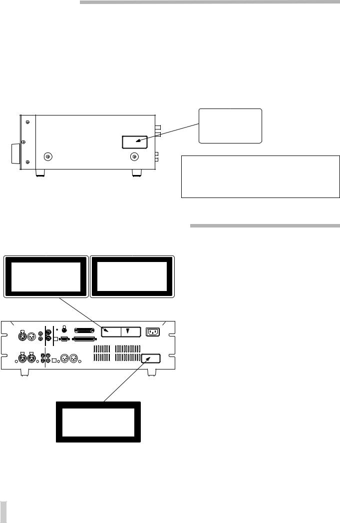
This product has been designed and manufactured according to FDA regulations "title 21, CFR, chapter 1, subchapter J, based on the Radiation Control for Health and Safety Act of 1968", and is classified as class 1 laser product. There is not hazardous invisible laser radiation during operation because invisible laser radiation emitted inside of this product is completely confined in the protective housings.
The label required in this reguration is shown 1.
… CAUTION
-DO NOT REMOVE THE PROTECTIVE HOUSING USING SCREWDRIVER.
-USE OF CONTROLS OR ADJUSTMENTS OR PERFORMANCE OF PROCEDURES OTHER THAN THOSE SPECIFIED HEREIN MAY RESULT IN HAZARDOUS RADIATION EXPOSURE.
-IF THIS PRODUCT DEVELOPS TROUBLE, MAKE A CONTACT WITH OUR SERVICEMAN, AND DO NOT USE THE PRODUCT IN A TROUBLED STATE.
For U.S.A.
1 |
CERTIFICATION |
|
|
|
|
|
THIS PRODUCT COMPLES WITH DHHS |
|
|
RULES 21 CFR SUBCHAPTER J APPLI- |
|
|
CABLE AT DATE OF MANUFACTURE |
|
|
TEAC CORPORATION |
|
|
3-7-3 NAKA-CHO, MUSASHINO-SHI, TOKYO, JAPAN |
|
|
MANUFACTURED |
TIF |
|
|
|
Optical pickup: Type : KMS-190A or KMS-190B Manufacturer: SONY Corporation Laser output: 0.25 mW Min. (Play), 5.0 mW Max. (Record) Wavelength: 780 nm ±20 nm
… CAUTION |
… ACHTUNG |
… OBSERVERA |
… ADVARSEL |
|
|
|
2 |
|
|
ADVARSEL - USYNLIG LASERSTRÅLING VED ÅBNING, NÅR |
CAUTION - INVISIBLE LASER RADIATION WHEN OPEN AND |
|||
|
INTERLOCKS DEFEATED. AVOID EXPOSURE TO BEAM. |
|||
SIKKERHEDSAFBRYDERE ER UDE AF FUNKTION. |
|
|||
|
|
|
||
UNDGÅ UDSÆTTELSE FOR STRÅLING. |
VORSICHT! |
UNSICHTBARE LASERSTRAHLUNGTRITT AUS. |
||
VAROITUS! SUOJAKOTELOA EI SAA AVATA. LAITE SISÄLTÄÄ |
|
WENN DECKEL GEÖFFNET UND WENN |
||
|
SICHERHEITSVERRIEGELUNG ÜBERBRÜCKT IST. |
|||
LASERDIODIN, JOKA LÄHETTÄÄ (NÄKYMÄTÖNTÄ) |
|
|||
SILMILLE VAARALLISTA LASERSÄTEILYÄ. |
|
NICHT DEM STRAHL AUSSETZEN ! |
||
|
|
|
||
ADVARSEL - USYNLIG LASERBESTRÅLING NÅR DENNE DELEN ER |
VARNING - |
OSYNLIG LASERSTRÅLNING NÄR DENNA DEL |
||
|
|
|
ÅPEN OG SIKKERHETSSPERREN ER UTKOBLET. |
ÄR ÖPPNAD OCH SPÄRR ÄR URKOPPLAD. |
|
||||
|
|
|
UNNGÅ UTSETTELSE FOR STRÅLING. |
STRÄLEN ÄR FARLIG. |
|
||||
|
|
|
|
|
|
|
|
||
|
|
|
|
|
|
|
|
|
|
|
|
|
|
|
|
|
|
|
|
|
|
|
|
|
|
|
|
|
|
|
|
|
|
|
|
|
|
|
|
|
|
|
|
|
|
|
|
|
|
|
|
|
|
|
|
|
|
|
|
|
|
|
|
|
|
|
|
|
|
1
CLASS 1 LASER PRODUCT
LUOKAN 1 LASERLAITE
KLASS 1 LASERAPPARAT
1THIS LABEL IS ATTACHED TO THE PLACE AS ILLUSTRATED TO INFORM THAT THE APPARATUS CONTAINS A LASER COMPONENT.
1DIESE AUFKLEBEMARKE IST AN DEM IN DER ABBILDUNG GEZEIGTEN ORT ANGEBRACHT UM DARAUF HINZUWEISEN, DASS IM INNERN DES GER
1PÅSKRIFTEN SITTER PÅ APPARATEN SOM VISAS SOM UPPMANING OM ATT APPARATEN OMFATTAR EN INBYGGD LASERKOMPONENT.
1DETTE MÆRKAT ER ANBRAGT SOM VIST I ILLUSTRATIONEN FOR AT ADVARE BRUGEREN OM AT APPARATET INDEHOLDER EN LASERKOMPONENT.
2DETTE MÆRKAT ER SOM VIST PÅ ILLUSTRATIONEN ANBRAGT PÅ INDERSIDEN AF TOPDÆKSLET FOR AT ADVARE BRUGEREN OM AT YDERLIGERE FREMTRÆNGEN VIL VÆRE FORBUNDET MED FARE FOR AT UDSÆTTE SIG FOR LASERSTRÅLING.
ADVARSEL — BETJENING AF ANDRE KONTROLLER OG REGULATORER ELLER BENYTTELES AF ANDRE FREMGANGSMÅDER END BESKREVET HERI ER FORBUNDET MED FARE FOR UDSÆTTELSE FOR LASERSTRÅLING.
VARING: APPARATEN INNEHÅLLER LASER KOMPONENT MED STRÅLNING ÖVERSTIGANDE KLASS 1.
"ADVARSEL: USYNLIG LASERSTRÅLING VED ÅBNING NAR SIKKERHEDSAFBRYDERE ER UDE AF FUNKTION. UNDG UDSAETTELSE FOR STRÅLING"
"VAROITUS! SUOJAKOTELOA EI SAA AVATA. LAITE SIS LASERDIODIN. JOKA L
VAARALLISTA LASERS
ADVARSEL: USYNLIG LASERBESTRÅLING NÅR DENNE DELEN ER ÅPEN OG SIKKERHETSSPERREN ER UTKOBLET UNNGÅ UTSETTELSE FOR STRÅLING.
4 –– TASCAM MD-801R/P Mk II

1 - Introduction
1.1 About the MiniDisc format ................ |
1-1 |
|
1.1.1 ATRAC compression .......................... |
1-1 |
|
1.1.2 Buffer memory .................................... |
1-1 |
|
1.1.3 Random access and U-TOC............... |
1-1 |
|
1.1.4 Track titling, etc. ................................. |
1-2 |
|
1.2 Care of MD media............................... |
1-2 |
|
1.3 About the MD-801R/P Mk II................ |
1-2 |
|
1.3.1 Unpacking the unit.............................. |
1-3 |
|
1.3.2 Rack-mounting the unit...................... |
1-3 |
|
1.3.3 Care of the unit.................................... |
1-3 |
|
1.3.4 Backup memory .................................. |
1-4 |
|
1.4 About this manual.............................. |
1-4 |
|
2 - Front and rear panel features |
|
|
2.1 Front panel.......................................... |
2-1 |
|
[1] POWER switch........................................ |
2-1 |
|
[2] Disc drive ................................................ |
2-1 |
|
[3] EJECT key ............................................... |
2-1 |
|
[4] TRACK keys ............................................ |
2-1 |
|
[5] STOP key................................................. |
2-1 |
|
[6] PLAY key and indicator ......................... |
2-1 |
|
[7] READY key and indicator ...................... |
2-1 |
|
[8] RECORD key and indicator ................... |
2-1 |
|
[9] PHONES jack and level control............. |
2-2 |
|
[10] CALL key ............................................... |
2-2 |
|
[11] JOG key and indicator ......................... |
2-2 |
|
[12] JOG/DATA dial...................................... |
2-2 |
|
[13] SHUTTLE wheel .................................... |
2-2 |
|
[14] Display |
................................................... |
2-2 |
[15] MENU key .............................................. |
2-2 |
|
[16] TITLE key............................................... |
2-2 |
|
[17] TIME key ................................................ |
2-2 |
|
[18] EDIT key ................................................ |
2-3 |
|
[19] TOC WRITE .............key and indicator |
2-4 |
|
[20] AUTO READY .........key and indicator |
2-4 |
|
[21] AUTO CUE ..............key and indicator |
2-4 |
|
[22] PLAY MODE ...................................key |
2-4 |
|
[23] MEMO IN/CAPS ......key and indicator |
2-4 |
|
[24] LOC A/DEL & LOC B/INSERT keys |
|
|
and indicators ........................................... |
2-4 |
|
[25] PITCH CONT ...........key and indicator |
2-4 |
|
[26] REPEAT ..................key and indicator |
2-4 |
|
[27] INPUT LEVEL .........................controls |
2-5 |
|
[28] INPUT selection ........................switch |
2-5 |
|
[29] DIGITAL .........................INPUT switch |
2-5 |
|
[30] REC MODE ................................switch |
2-5 |
|
[31] ANALOG ........................INPUT switch |
2-5 |
|
2.2 Display ................................................ |
|
2-5 |
(1) RESUME .................................indicator |
2-5 |
|
(2) .................................. |
indicator |
2-5 |
(3) CAPS indicator ...................................... |
2-5 |
|
(4) EDIT indicator ........................................ |
2-5 |
|
(5) DATE indicator....................................... |
2-5 |
|
(6) TRACK TITLE .........................indicator |
2-5 |
|
(7) DISC TITLE .............................indicator |
2-6 |
|
(8) TRACK NO. ........display and indicator |
2-6 |
|
(9) Time display .................and indicators |
2-6 |
|
Table of Contents
(10) PGM NO................................................. |
2-6 |
|
(11) Dot-matrix alphanumeric display ....... |
2-6 |
|
(12) TOC EDIT indicator .............................. |
2-6 |
|
(13) EOM ....................................................... |
2-6 |
|
(14) Peak level meters ................................. |
2-6 |
|
(15) REPEAT indicator ................................ |
2-6 |
|
(16) SINGLE indicator.................................. |
2-6 |
|
(17) A–B indicator........................................ |
2-6 |
|
2.3 |
Rear panel .......................................... |
2-6 |
[32] DIGITAL INPUT (AES/EBU)................... |
2-6 |
|
[33] DIGITAL OUTPUT (AES/EBU)............... |
2-6 |
|
[34] DIGITAL INPUT (COAXIAL) .................. |
2-7 |
|
[35] DIGITAL OUTPUT (COAXIAL) .............. |
2-7 |
|
[36] ANALOG INPUTS and trimmers |
|
|
|
(BALANCED) .............................................. |
2-7 |
[37] ANALOG INPUTS (UNBALANCED)...... |
2-7 |
|
[38] ANALOG OUTPUTS (MONITOR) .......... |
2-7 |
|
[39] Analog output function DIP switch |
|
|
|
bank ............................................................ |
2-7 |
[40] ANALOG OUTPUTS (LINE) and |
|
|
|
trimmers ..................................................... |
2-7 |
[41] WORD SYNC IN ..................................... |
2-8 |
|
[42] WORD SYNC THRU............................... |
2-8 |
|
[43] MODE SET DIP switch bank................. |
2-8 |
|
[44] KEYBOARD connector ......................... |
2-8 |
|
[45] REMOTE (SERIAL) connector.............. |
2-8 |
|
[46] REMOTE CONTROL connector............ |
2-8 |
|
[47] REMOTE (PARALLEL) connector........ |
2-8 |
|
[48] ~ IN (power in connector) ..................... |
2-8 |
|
3 - Menu items |
|
|
3.1 |
Basic principles of menu operations3-1 |
|
3.2 |
Pitch control....................................... |
3-1 |
3.3 |
Auto cue ............................................. |
3-1 |
3.4 |
Frame display .................................... |
3-1 |
3.5 |
Jog loop length.................................. |
3-1 |
3.6 |
Resume setting.................................. |
3-2 |
3.7 |
EOM disc ............................................ |
3-2 |
3.8 |
EOM track........................................... |
3-2 |
3.9 |
Timer-controlled playback................ |
3-2 |
3.10 Incremental play .............................. |
3-3 |
|
3.11 Serial communications ................... |
3-3 |
|
3.11.1 Baud rate ............................................ |
3-3 |
|
3.11.2 Word length........................................ |
3-3 |
|
3.11.3 Parity................................................... |
3-3 |
|
3.11.4 Stop bits ............................................. |
3-3 |
|
3.12 Check items ..................................... |
3-3 |
|
3.12.1 Spindle motor time ............................ |
3-4 |
|
3.12.2 Laser pickup time .............................. |
3-4 |
|
3.12.3 System software version .................. |
3-4 |
|
3.13 Auto track numbering level ............ |
3-4 |
|
3.14 Copy ID ............................................. |
3-4 |
|
3.15 Post-script recording ...................... |
3-4 |
|
4 - Basic operations |
|
|
4.1 |
Inserting and ejecting discs ............. |
4-1 |
4.2 |
Playback of discs .............................. |
4-1 |
TASCAM MD-801R/P Mk II –i

Table of Contents
4.2.1 Playing back a whole disc.................. |
4-1 |
4.2.2 Playback outputs ................................ |
4-1 |
4.2.3 Monaural playback.............................. |
4-1 |
4.2.4 Playing back a single track ................ |
4-2 |
4.2.5Entering the A and B location points 4-2
4.2.6Playback between two location
points ......................................................... |
4-2 |
4.2.7 The CALL function .............................. |
4-2 |
4.2.8 Relative time display .......................... |
4-2 |
4.2.9 Repeat playback.................................. |
4-3 |
4.2.10 Track search operations .................. |
4-3 |
4.2.11Cueing the next track automatically 4-3
4.2.12Cueing to the first audio position in
|
a track ........................................................ |
4-3 |
4.2.13 Varispeed mode ................................ |
4-3 |
|
4.2.14 Jog mode ........................................... |
4-3 |
|
4.2.15 Shuttle mode ..................................... |
4-4 |
|
4.2.16 Displaying track titles during |
|
|
|
playback..................................................... |
4-4 |
4.2.17 Displaying the recording date ......... |
4-4 |
|
4.2.18 Setting the time and date ................. |
4-4 |
|
4.3 |
Recording operations........................ |
4-4 |
4.3.1 General notes on recording using the |
||
|
MD format .................................................. |
4-5 |
4.3.2 Rebuilding the TOC ............................ |
4-5 |
|
4.3.3 Basic recording ................................... |
4-5 |
|
4.3.4 Track number incrementing............... |
4-6 |
|
4.3.5 “Post-Script” recording...................... |
4-6 |
|
4.3.6 Replace recording............................... |
4-6 |
|
4.3.7 Sound synchro recording .................. |
4-7 |
|
4.3.8 Digital recording ................................. |
4-7 |
|
4.3.9 Analog recording ................................ |
4-8 |
|
4.3.10 Track title copying together with |
|
|
|
audio .......................................................... |
4-8 |
5 - Editing operations |
|
|
5.1 |
Basic editing operations ................... |
5-1 |
5.1.1 Cancelling an edit operation .............. |
5-1 |
|
5.1.2 Editing without saving the edits to |
|
|
|
disc............................................................. |
5-1 |
5.2 |
Dividing tracks ................................... |
5-1 |
5.3 |
Erasing a track ................................... |
5-2 |
5.4 |
Combining tracks .............................. |
5-2 |
5.5 |
Moving tracks..................................... |
5-3 |
5.6 |
A and B point erase operations........ |
5-3 |
5.6.1 Normal A-B erase................................. |
5-4 |
|
5.6.2 Erasing to the end of a track .............. |
5-4 |
|
5.6.3 Erasing from the start of a track ........ |
5-4 |
|
5.6.4 Erasing more than one track at a |
|
|
|
time ............................................................. |
5-4 |
5.6.5 Retaining a track title for use by the |
|
|
|
second track after a division .................... |
5-5 |
5.7 |
Moving an A-B point .......................... |
5-5 |
5.8 |
Restoring erased material ................. |
5-6 |
5.9 |
Changing track attributes.................. |
5-6 |
5.10 Erasing a complete disc .................. |
5-7 |
|
5.11 Track and disc title entry................. |
5-7 |
|
5.11.1 Deleting characters ........................... |
5-8 |
|
5.11.2 Inserting characters .......................... |
5-8 |
|
5.11.3 Changing characters ......................... |
5-8 |
|
5.11.4 Editing existing titles......................... |
5-8 |
|
5.11.5 Viewing titles...................................... |
5-8 |
|
5.11.6 Copying disc and track titles............ |
5-9 |
|
6 - Use of a keyboard with the MD-801 |
|
|
6.1 |
General transport operations............ |
6-1 |
6.2 |
Edit operations, etc............................ |
6-1 |
6.2.1 Entering programmed playback......... |
6-1 |
|
6.2.2 Checking and editing a programmed |
|
|
|
sequence .................................................... |
6-2 |
6.2.3 Time-based location ............................ |
6-2 |
|
6.3 |
Flash start ........................................... |
6-2 |
6.4 |
Direct track entry................................ |
6-3 |
6.5 |
Track and disc title editing with the |
|
keyboard ................................................ |
6-3 |
|
7 - Remote control of the MD-801 |
|
|
7.1 REMOTE (PARALLEL) connector..... |
7-1 |
|
7.1.1 Tally indicators .................................... |
7-1 |
|
7.1.2 Fader start ............................................ |
7-2 |
|
7.1.3 Sequential playback and recording ... |
7-2 |
|
8 - Specifications, etc. |
|
|
8.1 |
Error messages and troubleshooting |
|
guide....................................................... |
8-1 |
|
8.2 |
Specifications..................................... |
8-2 |
8.2.1 General MiniDisc ................................. |
8-2 |
|
8.2.2 Analog I/O............................................. |
8-3 |
|
8.2.3 Digital I/O .............................................. |
8-3 |
|
8.2.4 Other connections ............................... |
8-3 |
|
8.2.5 General and electrical ......................... |
8-3 |
|
8.3 |
Dimensional drawing ......................... |
8-4 |
–ii TASCAM MD-801R/P Mk II

This manual covers the two models of the MD-801 Mk II product line: the MD-801R Mk II, which is capable of recording and playing back on MiniDisc media, and the MD-801P Mk II, which is for playback only of such media. Apart from the recording and associated facilities provided on the MD-801R, the functionality and specifications of the two units are identical. For brevity, the unit will be referred to as the “MD-801” in instances where there is no difference between the recording and playback models.
When a section of this manual describes a function which is included as part of the MD-801R only, the section will be marked as below:
R3.12.2Laser pickup time
This indicates how long…
There are no features which are unique to the MD801P model.
1.1 About the MiniDisc format
This section provides some basic information regarding the MiniDisc format. If more detailed information is required, the reader is referred to one of the many books on the subject. John Wilkinson, The Art of Digital Audio 2nd ed. Oxford: Focal Press, 1994 is an excellent reference source, particularly Chapter 12, which deals with the use of optical discs in audio applications.
The MiniDisc format (MD) is a convenient form of digital audio media, using optical playback, similar to CDs.
The format of the MD is substantially smaller than that of the CD, and the disc itself is housed in a cartridge with a shutter, similar to that of a 3.5” floppy disc drive. The disc platter should never be removed from this cartridge.
Pre-recorded MDs, which are manufactured in the same way as commercial CDs, using a stamper process, are read using a laser beam to read the pits stamped onto the disc.
Recordable MDs are also available, and the technology used for recording on a recordable MD is magento-optical, allowing the disc to be re-used many times. Shutters on both sides of the disc allow access to the disc surface by the recorder’s laser and magnetic head.
There is a third kind of MD, the hybrid, which contains pre-recorded pits at the center of the MD, together with an area reserved for user recording.
1 - Introduction
Full explanations of the principles of magneto-opti- cal recording may be found in a number of excellent reference works, but briefly, during the recording process, the disc is exposed to a strong laser beam which heats the disc’s magnetic medium so that a magnetic field can be applied to change the orientation of the magnetic particles. On cooling, this orientation is permanently fixed, unless the disc is reheated and re-recorded.
The MD format therefore provides the convenience and durability of an optical disc format with the reusabilty characteristics of tape.
1.1.1 ATRAC compression
If a MiniDisc were to be recorded using exactly the same techniques as a CD, the playback time would be only 15 minutes of stereo playback.
However, using a technique known as ATRAC (Adaptive TRansform Acoustic Coding), 74 minutes of stereo audio at 44.1 kHz sampling frequency with a 16-bit word length can be recorded on an MD.
ATRAC uses two important pyscho-acoustic principles to reduce the size of the recorded data: the greater sensitivity of the human ear to mid-range signals, relative to bass and treble signals, and the “masking” effect, whereby quieter signals are hidden by louder ones.
The ATRAC used in the MD-801R/P Mk II is a very recent version of this encoding scheme (4.5), resulting in an almost inaudible loss of signal quality.
1.1.2 Buffer memory
The ATRAC compression scheme has an additional advantage, as a RAM buffer must be provided for the compressed data, before it is decoded and sent to the D/A converters.
On the MD-801R/P Mk II, this buffer memory holds about 10 seconds’ worth of data. The advantage is that, unlike a CD player, the MD-801R/P Mk II is not vulnerable to mechanical shocks and vibration, etc., which can cause a CD player playback pickup to jump and cause audible skipping.
1.1.3 Random access and U-TOC
The format of a recordable MD is much closer to that of a computer disc than of conventional audio media. The random access nature of the disc media allows a logical “track” to be composed of sections of audio data recorded at different points on the disc.
In the same way that a computer’s operating system hides the details of the way that data is stored on the
TASCAM MD-801R/P Mk II 1–1

1 - Care of MD media
disk from the user, and a file appears as one contiguous block of data (even though it may be spread over many tracks and sectors of the disk), the MD player allows separated audio data to appear as a continuous audio track.
The MD-801 allows the creation and reading of a User Table of Contents (U-TOC) on recordable discs, which contain instructions to the player on the logical arrangement of the tracks, where to find the next audio segment to be played, etc. This is similar to the directory tracks provided as part of a computer disk operating system.
The random access facilities provided by the MD801 are significantly better than those to be found on consumer MD decks. The effective start time can be effectively zero, compared with hundreds of milliseconds on consumer units.
1.1.4 Track titling, etc.
In common with other forms of digital audio media, the MD medium allows other data to be recorded alongside the audio data. In the MD medium, this is used to provide alphanumeric disc and track titles, which are shown on the display of the player.
In the case of the MD-801R/P Mk II, this information may be conveniently entered through a standard computer keyboard (PS/2 compatible), or through the controls of the main unit.
In addition, a realtime clock allows dateand timestamping of tracks recorded on the unit or created or edited through TOC editing functions.
These times will be displayed when the disc is replayed on any one of the MD-801 series.
1.2 Care of MD media
The MD medium has been designed to be robust, and the integration of the disc into a cartridge protects the recorded surface from the worst effects of dust, fingerprints, and scratches.
Even so, there are some commonsense precautions that you should take when storing and handling MiniDiscs.
•Do not open the shutter and touch the surface of the disc.
•Do not keep MiniDiscs in excessively dusty locations, in direct sunlight, in areas subject to high temperatures, or high levels of humidity.
•If the cartridge becomes dirty, clean it with a dry, soft cloth. Do not use any solvents or other liquids.
1.3 About the MD-801R/P Mk II
The MD-801R/P Mk II, based on the TASCAM MD801 series of MD recorder/players, and designed to meet the requirements of audio professionals, includes the following features:
•Full editing functions to divide, erase and combine tracks, etc.
•Auto cue function, allowing the playback point to be automatically cued to the first frame of a track, using a selectable sensitivity level
•Auto ready function, allowing the playback point to be “parked” in the play ready mode at the start of each track
•A resume function, which holds in backup memory the point where playback stopped, or the power was disconnected
•Incremental play mode, allowing cueing of the playback point to the start of the next track, as determined by a selectable audio threshold level, when playback is stopped
•“Soft mute” eliminates clicks, etc. when pausing and restarting playback
•Dual time display
•Three playback modes: normal (whole disc), track play, and A-B play (between two defined points)
•3-point autolocation facility
•Repeat (disc, track, A-B)
•Either stereo or monaural playback may be selected
•Pitch change ±9.9% in 0.1% steps
•Shuttle operations up to 100 x normal speed, and jog to single-frame accuracy
•Digital outputs in COAXIAL (SPDIF) and AES/ EBU
•Word clock synchronization for inclusion of the MD-801 in an all-digital audio setup
•Two sets of analog outputs: –10 dBV unbalanced MONITOR (RCA) and +4 dBu balanced LINE (XLR-type). The LINE outputs may be trimmed for precise signal matching with other equipment
•Output selectable (using remote controllers) from either MONITOR or LINE
•High-quality DA convertor for optimum analog audio quality
•Level 4.5 ATRAC system
•PS/2-compatible computer keyboard connector allows titling and other remote control operations
1–2 TASCAM MD-801R/P Mk II
to be conveniently carried out using a standard keyboard
•Remote control possible from dedicated TASCAM remote control units (RC-801, RC-FS10/20, and RC-8), or through industry-standard parallel or serial interfaces
•Tally signals sent to controlling device at the end of each track played back
•Optional RAM buffer expansion module (BU-801) allows flash start of track playback
RIn addition, the MD801R Mk II provides the following features:
•20-bit A/D converter for increased audio quality when recording
•Selectable Copy ID modes, including the SCMS standard
•Integral sampling frequency converter, allowing digital recording from material recorded at frequencies other than 44.1 kHz (48 kHz and 32 kHz)
•Digital inputs in both SPDIF and AES/EBU formats
•The ability to record in monaural mode, doubling the recording time available on a disc.
•Analog inputs in both +4 dBu balanced (XLRtype) and –10 dBV unbalanced (RCA) formats. The balanced inputs may be trimmed to match input signal levels
•Replace recording function, allowing recording to be carried out in the middle of a track, while retaining the track title
•Sound sync function to allow the unit to start recording automatically when a selectable audio threshold level is exceeded
•Title dubbing from another MD-801 unit (requires optional connecting cable PW-1XMD)
•Realtime clock for dateand timestamping recorded material
1.3.1 Unpacking the unit
When you unpack the unit, as well as the unit itself and this manual, you should find:
•Power cord
•Rack-mount kit
•Warranty card
If any items are missing, contact your TASCAM dealer.
1 - About the MD-801R/P Mk II
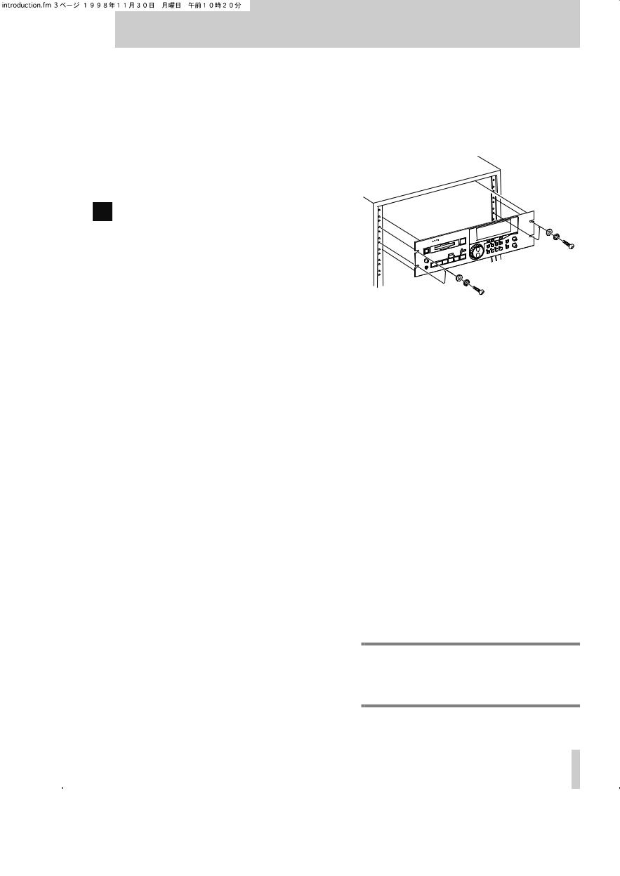
1.3.2 Rack-mounting the unit
The MD-801 is equipped with integral rack-mount ears, and may be installed in any standard vertical 19” rack.
Remove the feet from the MD-801 using a Phillips screwdriver before installing the unit.
In addition to the 3U of space required for the MD801 itself, we strongly suggest leaving at least 1U of empty rack space above the MD-801 for ventilation purposes.
1.3.3 Care of the unit
The commonsense precautions that you should take with any piece of precision electronic equipment also apply to the MD-801. In particular:
•Do not subject the unit to severe shocks or vibration. Despite the buffer mechanism mentioned above, there is a risk of data loss, particularly while recording.
•Do not use the unit in very dusty or smoky environments. If the optical lens or the head becomes dirty as the result of such use, use a commercially-avail- able MD lens and head cleaner to clean the lens.
•The exterior of the unit may be cleaned with a soft dry cloth, or a cloth barely dampened with a mild detergent solution. Do not use any solvent, thinner or alcohol-based cleaning agents to clean the unit.
The date and time clock (for timestamping of recordings and edits) is powered by a lithium battery. We suggest that this battery is changed about every two years.
NOTE
Do not attempt to change this battery by yourself. Get an authorized TASCAM service center to perform this operation for you.
TASCAM MD-801R/P Mk II 1–3

1 - About this manual
1.3.4 Backup memory
When the unit is powered down, the following settings are memorized.
•AUTO READY status (see [20])
•AUTO CUE settings and status (see [21])
•The last used PLAY mode (see [22])
•The two LOC points (A and B) (see [24])
•Pitch control settings and status (see [25])
•REPEAT status (see 4.2.9, "Repeat playback")
•Menu settings (see 3, "Menu items")
•If the resume function is turned on, the resume point is memorized
1.4 About this manual
This manual has been organized so that you should be able to find the section you need relatively quickly. We suggest that you familiarize yourself with at least the Table of Contents, so that you know where to look if you need information on a particular aspect of the unit’s operation.
An index is also provided, which should assist you in locating the desired section.
As mentioned earlier, when a section of this manual describes a function which is included as part of the MD-801R only, the section will be marked as below:
R3.12.2Laser pickup time
This indicates how long…
There are no features which are unique to the MD801P model only.
When characters are shown on the unit’s dot-matrix display, the following typeface is used: Input Mon. Alternatively, the alphanumeric display itself may be shown:
TITLE ?
If a “preset” word or phrase is shown on the display, this is shown as follows: TRAC K TITLE.
Track times, program numbers, as shown in 7-digit numbers, are shown as 034, etc.
If a front panel control or rear panel connection is mentioned, the following typeface is used (a little larger than that used for preset display words): TOC WRITE. The number of the control or connection, as given in 2, "Front and rear panel features", may also be given, e.g. [5].
If a front panel control or rear panel connection of another unit is specifically named, the folloiwng typeface is used: WORD IN.
When an optional PS/2-compatible keyboard is connected to the MD-801, the keyboard keys are represented in the following typeface:
Press F1 to go back by one track.
If two keys are to be pressed together (i.e. the firstnamed key is to be pressed and held down while the second is pressed), this is represented as:
Press SHIFT + F1 to enter the erase track editing function.
• d
1–4 TASCAM MD-801R/P Mk II

1 - Hookup Examplel
1.5 Hookup Examplel
TASCAM MD-801R/P Mk II 1–5

2 - Front and rear panel features
2–1 TASCAM MD-801R/P Mk II
2 - Front and rear panel features
This section, as well as giving a description of the controls and features of the MD-801, also provides many descriptions of basic operations.
The section on the rear panel also contains advice on setting up and connecting the MD-801 as part of an audio system.
[4] TRACK keys
These keys are used to move the playback position backwards or forwards a track at a time. Their use is detailed in 4.2, "Playback of discs".
[5] STOP key
This key stops playback or recording (MD-801R only). It is also used to cancel other operations.
2.1 Front panel
The following provides details of the basic functions associated with the front panel controls of the unit. If further information on the use of a particular control is provided elsewhere in the manual, this is indicated.
[1] POWER switch
Press once to turn on the unit, and again to turn the unit off.
NOTE
You should not turn the unit off while the U- TOC (1.1.3, "Random access and U-TOC") is being written. If power is disconnected from the unit the U-TOC is being written, the disc data will be corrupted, and the disc may become unreadable.
Always remember to press the TOC WRITE key [19] before turning off power to the unit, in order to save your edits to disc.
[2] Disc drive
Insert MiniDiscs into this slot, label uppermost, and with the arrow pointing into the drive.
Use the EJECT key [3] to eject discs.
[3] EJECT key
Press this key to eject discs from the drive.
NOTE
If you press the EJECT key when the TOC WRITE indicator [19] is lit, indicating that there are edits that have been made, but not yet saved to disc as part of the U-TOC, the display will show TOC Edited!. If you press the EJECT key again, you can eject the disc, but all edits made since the last U-TOC writing operation will be lost. If you want to save the edits to disc, press the TOC WRITE key.
[6] PLAY key and indicator
Used to start playback or recording (MD-801R only). When the operation is taking place, the key’s indicator lights.
[7] READY key and indicator
Used to put the unit into play ready or record ready (MD-801R only) mode. The indicator lights when the unit is ready.
To start the operation, press the PLAY key [6].
RIf recording is taking place while the READY key is pressed, the unit goes into record ready mode. The current track number is incremented by one, to show that the next recording will start a new track, if Postscript recording is turned on (see 3.15, "Post-script recording").
To cancel a ready operation, press the STOP key [5].
R [8] RECORD key and indicator
If the unit is stopped, pressing the RECORD key will enter “input monitor” mode (the RECORD indicator lights) and Input Mon appears on the display. This is valid whether or not a disc is loaded in the drive.
In input monitor mode, the signals received at the appropriate connectors, as selected with the input switches ([28], [29] and [31]) are routed to the outputs for monitoring as well as to the PHONES jack [9], and the unit’s meters are used to display the signal levels. If the selected digital signal is not available, the D-IN UNLOCK! message is displayed.
The input level of the signals input at the analog jacks may be adjusted using the INPUT LEVEL controls [27].
If the RECORD key is pressed and held down, and the READY key is pressed, the unit enters record ready mode (a disc must be in the drive). Both the RECORD and READY indicators will light.
TASCAM MD-801R/P Mk II 2–2

2 - Front panel
To start recording, press the PLAY key [6]. To stop recording, press the STOP key [5]. After the STOP key has been pressed, the words TO C EDIT will flash on the display, which will also show UTOC Writing as the U-TOC is written to disc.
To cancel record ready mode, press the STOP key
[5].
[9] PHONES jack and level control
Connect a pair of standard stereo headphones to this 1/4” jack. Adjust the level with the LEVEL control. The maximum output power is 50 mW per channel, and the impedance is 32 Ω.
[10] CALL key
This key allows you to return to the point where the READY key [7] was last pressed while the unit was in play ready mode. The unit will return to this point, and enter play ready mode (READY and PLAY indicators lit). See also 4.2.7, "The CALL function".
RThe MD-801R also automatically sets the call point at the point where recording last started. This enables easy return to the point where the recording started, using the CALL key, in order to check a take, etc.
It may also be used to locate to the point which has been located with the JOG dial [12].
[11] JOG key and indicator
Use this key for precise positioning of the playback point, in combination with the JOG/DATA dial [12]. When the jog mode is active, the JOG indicator above this key is lit.
[12] JOG/DATA dial
When the JOG indicator [11] is lit, this dial functions as a jog dial, allowing precise positioning of the playback point (confirmed with the READY key [7]). See 4.2.14, "Jog mode" for full details of this process.
When the JOG indicator is not lit, the dial is used as a data entry dial for entering values, titling characters, etc. Typically, turning this dial clockwise increases the data value, and turning it counterclockwise decreases the value.
[13] SHUTTLE wheel
This wheel can be used for shuttle playback (forwards or backwards) when the unit is in play or play ready mode. Since the MD-801 is a digital audio device, the sound output during shuttle play is not
continuous.
The further the shuttle wheel is turned from the center position, the faster the shuttle playback speed.
When the unit is in menu mode, this wheel is used in the MD-801’s menu system. Turning it clockwise generally confirms an action, and turning it counterclockwise acts as an “escape” action. It is also used as a cursor control in titling operations.
[14] Display
See 2.2, "Display" below for details of the different components that make up the display.
[15] MENU key
The MENU key is used to cycle through the different menus that allow the setting of different parameters affecting the operation of the MD-801. See 3, "Menu items" for full details of the menus and the different options available in them.
[16] TITLE key
The TITLE key is used to show both disc and track titles. It is also used to display the date and time when the MEMO IN/CAPS key indicator [23] is lit.
See 4.2.16, "Displaying track titles during playback" and 4.2.17, "Displaying the recording date" for details.
[17] TIME key
The TIME key is used to cycle through the folloiwng time display modes on the upper 7-segment numeric indicators of the display during playback or in play ready mode:
•(no indication)—the time elapsed from the start of the current track
•REMAIN—the playback time remaining in the current track
•TOTAL —the total elapsed time from the start of the disc
•TOTA L REMAIN—the total time remaining on the disc
It is also possible to make a time display which is relative to a “zero point” (see the section on 4.2.8, "Relative time display").
RWhen the unit is in record or record ready mode, the meanings change slightly, as shown below:
•(no indication)—the time elapsed from the start of the track currently being recorded
2–3 TASCAM MD-801R/P Mk II

• R E M A I N—the total time remaining on the disc for further recording (the length of the blank portion of the disc)
• TOTA L —the total elapsed time from the start of the disc
• TOTA L REMAIN—the total time remaining on the disc for further recording (the same as REMAIN)
If the MEMO IN/CAPS indicator [23] is lit, the unit is in play or play ready mode, and the TIME key is pressed, the lower (alphanumeric dot-matrix) part of the display may be used to give timing information. This is represented as follows:
•elp—the time elapsed from the start of the current track
•rem—the playback time remaining in the current track
•tel—the total elapsed time from the start of the disc
•tre—the total time remaining on the disc
•rel—the time relative to a user-settable “zero point” (see 4.2.8, "Relative time display")
RWhen the unit is in record or record ready mode, and the MEMO IN/CAP indicator [23] is lit, and the TIME key is pressed, the lower (alphanumeric dotmatrix) part of the display may be used to give timing information. This is representated as follows:
•elp—the time elapsed from the start of the track currently being recorded
•rem—the total time remaining on the disc for further recording (the length of the blank portion of the disc)
•tel—the total elapsed time from the start of the disc
•tre—the total time remaining on the disc for further recording (the same as rem)
•rel—the time relative to a user-settable “zero point” (see 4.2.8, "Relative time display")
It is therefore possible to have two separate time indicators shown simultaneously. Note that if both the upper and lower parts of the display are set to the same time indication, there may be occasions where the two values shown do not always match exactly.
To turn off the time display in the lower part of the display, press the TIME key until the disc or track title is shown, rather than the time display.
In the play and play ready, as well as the record and record ready modes, the TIME key can also be used
2 - Front panel
to display the following:
•aay bbm ccd—where aa is the year, bb is the month, and cc is the day of the date according to the MD-801’s internal clock.
•eeh ffm ggs—where ee is the hour (in 24-hour format), ff the minutes and gg the seconds of the time of day according to the MD-801’s internal clock.
If the internal clock needs to be adjusted, follow the procedure described in 4.2.18, "Setting the time and date".
[18] EDIT key
The EDIT key is used to access various data and disc editing modes, as detailed below.
When the EDIT key is pressed, the JOG/DATA dial [12] is used to cycle through the various editing options as detailed below.
When an editing mode is shown, followed by a question mark, turning the SHUTTLE wheel [13] clockwise will enter that editing mode.
To exit the editing mode, the SHUTTLE wheel can be turned counterclockwise, the EDIT key can be pressed once again, or the STOP key [5] can be pressed.
The following is a list and brief description of the editing functions available. Full details are given in 5, "Editing operations":
• DIVIDE?—Divides a track into two tracks
• ERASE TRK?—Erases a track
•COMBINE?—Joins two tracks into one
•MOVE?—Moves tracks in a sequence
• ERASE A-B?—Erases data between the A and B points
•INSERT A-B?—Commits an insertion to disc
•RESTORE?—Restore an erased track or section (can be regarded as an “undo” function)
• TRK ATTR?—Sets track attributes
•ERASE DISC?—Erases the contents of the disc
•TITLE?—Enters a track or disc title
NOTE
It is possible to perform editing operations on pre-recorded (read-only) discs. However,
TASCAM MD-801R/P Mk II 2–4

2 - Front panel
these edits cannot be committed to disc using the TOC WRITE function (see below).
[19] TOC WRITE key and indicator
After an edit operation has been selected and performed from the EDIT key [18], the TOC WRITE indicator will light, and the TO C EDIT indicator in the display will be lit. This is a reminder that the disc should not be ejected before the U-TOC has been written to disc.
Press the TOC WRITE key, and the editing data will be written to disc, during which time the TO C EDIT indicator in the display will flash.
See the explanation of the EJECT key [3] for details of how to eject a disc without writing the U-TOC, if this is required.
[20] AUTO READY key and indicator
Use this key to put the unit into auto ready mode (the indicator will light). The auto ready mode provides automatic “track at a time” playback.
When in auto ready mode, the unit will go into play ready mode when the start of a track is reached in playback. See 4.2.11, "Cueing the next track automatically" for full details.
[21] AUTO CUE key and indicator
Use this key to put the unit into auto cue mode (the indicator will light). The auto cue mode allows the elimination of “dead time” at the start of tracks, allowing easy pre-cuing of commercials, jingles, Foley effects, etc.
When the unit is in auto cue mode and stopped, and the READY key [7] is pressed, the unit will search forward for the first audio frame above a given threshold level, and cue itself to that location. It will then enter play ready mode.
A similar process occurs when a track search operation has occurred.
See 4.2.12, "Cueing to the first audio position in a track" for further details.
[22] PLAY MODE key
Use this key to cycle between the different playback modes. This key is enabled in the stop and the play ready modes.
Both the display preset indicators and the alphanumeric part of the display are used to show the current playback mode status, as follows:
• SINGLE/SINGLE MODE—Single-track playback mode is selected
•(blank)/CONTINUE—Continuous play of a disc, from the start to the end
•A - B /A-B MODE—If the A and B points have been set (see [24]), playback will loop between these points
Once a playback mode has been selected, the REPEAT key [26] can be used to repeat the portion of the disc being played back (track, disc or A-B portion).
[23] MEMO IN/CAPS key and indicator
This key is used for a variety of functions: entering memory location points, acting as a “caps lock” key when entering disc and track titles, and as a display mode selector (see [17]), etc.
Its uses are described more fully in the various sections dealing with the functions that it controls.
[24]LOC A/DEL & LOC B/INSERT keys and indicators
These keys are used to set memory location points, which are used for location, repeat play, editing purposes, etc. These points are retained until the disc is ejected (including at power-off). See 4.2.5, "Entering the A and B location points" for details of how to set these positions.
These keys may also be used for locating to the points which have been set.
In title editing mode, the A and B keys are used to delete and insert characters, respectively. See 5.11, "Track and disc title entry".
[25] PITCH CONT key and indicator
Use this key to enter the pitch control mode (the indicator lights when this mode is active). When pitch control is active, the speed (and pitch) of playback can be altered by ±9.9%.
NOTE
Pitch control is not possible when the MD-801 is receiving its word clock from an external source (see [43]).
The exact amount of pitch control is set through a menu item (see 3.2, "Pitch control" for details).
[26] REPEAT key and indicator
Use this key to start repeat play of the selected playback portion of the disc (see [22]). When in repeat
2–5 TASCAM MD-801R/P Mk II
 Loading...