


 Loading...
» 9101413400
TM-D4000
Digital Mixing Console
OWNER’S MANUAL

Important Safety Precautions
ÜCOVER (OR BACK). NO USER-SERVICEABLE PARTS INSIDE. REFER SERVICING TO QUALIFIED SERVICE PERSONNEL.CAUTION: TO REDUCE THE RISK OF ELECTRIC SHOCK, DO NOT REMOVE
ÿThe lightning flash with arrowhead symbol, within an equilateral triangle, is intended to alert the user to the presence of uninsulated “dangerous voltage” within the product’s enclosure that may be of sufficient magnitude to constitute a risk of electric shock to persons..
The exclamation point within an equilateral triangle is intended to alert the user to the presence
Ÿof important operating and maintenance (servicing) instructions in the literature accompanying the appliance.
This appliance has a serial number |
|
|
WARNING: TO PREVENT FIRE OR SHOCK |
||||||||
located on the rear panel. Please record |
|
|
|||||||||
the model number and serial number |
|
|
HAZARD, DO NOT EXPOSE THIS |
||||||||
and retain them for your records. |
|
|
|
|
|||||||
Model number |
|
|
|
|
APPLIANCE TO RAIN OR MOISTURE. |
||||||
Serial number |
|
|
|
|
|
||||||
|
|
|
|
|
|
|
|
|
|
|
|
|
|
|
|
|
|
|
|
|
|
|
|
|
|
|
|
|
|
|
|
|
For U.S.A |
|
|
IMPORTANT (for U.K. Customers) |
|
|
|
|
|||||||
|
|
|
|
|
|||||||
|
|
TO THE USER |
|
||||||||
|
|
|
|
|
|
|
|
|
|
||
|
|
|
|
|
|
|
|||||
DO NOT cut off the mains plug from this equipment. |
|
|
This equipment has been tested and found to comply |
|
|||||||
If the plug fitted is not suitable for the power points in your home |
|
|
with the limits for a Class A digital device, pursuant to |
|
|||||||
or the cable is too short to reach a power point, then obtain an |
|
|
Part 15 of the FCC Rules. These limits are designed |
|
|||||||
appropriate safety approved extension lead or consult your |
|
|
to provide reasonable protection against harmful |
|
|||||||
dealer. |
|
|
|
|
|
|
|
interference when the equipment is operated in a |
|
||
If nonetheless the mains plug is cut off, remove the |
|
|
commercial environment. This equipment generates, |
|
|||||||
|
|
uses, and can radiate radio frequency energy and, if |
|
||||||||
fuse and dispose of the plug immediately, to avoid |
|
|
|
||||||||
|
|
not installed and used in accordance with the |
|
||||||||
a possible shock hazard by inadvertent connection to the mains |
|
|
|
||||||||
|
|
instruction manual, may cause harmful interference to |
|
||||||||
supply. |
|
|
|
|
|
|
|
|
|||
|
|
|
|
|
|
|
radio communications. |
|
|||
|
|
|
|
|
|
|
|
|
|
||
If this product is not provided with a mains plug, or one has to be |
|
|
Operation of this equipment in a residental area is |
|
|||||||
|
|
likely to cause harmful interference in which case the |
|
||||||||
fitted, then follow the instructions given below: |
|
|
|
|
|||||||
|
|
|
user will be required to correct the interference at his |
|
|||||||
IMPORTANT: The wires in this mains lead are coloured in |
|
|
|
||||||||
|
|
own expense. |
|
||||||||
accordance with the following code: |
|
|
|
|
|
|
|||||
GREEN-AND-YELLOW |
: EARTH |
|
|
|
CAUTION |
|
|||||
|
|
|
Changes or modifications to this equipment not |
|
|||||||
BLUE |
: NEUTRAL |
|
|
|
|||||||
|
|
expressly approved by TEAC CORPORATION for |
|
||||||||
BROWN |
: LIVE |
|
|
|
|
||||||
|
|
|
compliance could void the user’s authority to operate |
|
|||||||
WARNING: This apparatus must be earthed. |
|
|
|
|
|||||||
|
|
|
this equipment. |
|
|||||||
As the colours of the wires in the mains lead of this apparatus may |
|
|
|
|
|
||||||
|
|
|
|
|
|||||||
not correspond with the coloured markings identifying the |
|
|
|
|
|
||||||
terminals in your plug proceed as follows: |
|
|
|
For the consumers in Europe |
|||||||
The wire which is coloured GREEN-and-YELLOW must be |
|
|
WARNING |
||||||||
connected to the terminal in the plug which is marked by the letter |
|
|
This is a Class A product. In a domestic environment, this |
||||||||
|
|
product may cause radio interference in which case the user |
|||||||||
E or by the safety earth symbol ç or coloured GREEN or |
|
|
|||||||||
|
|
may be required to take adequate measures. |
|||||||||
GREEN-and-YELLOW. |
|
|
|
|
|
|
|
||||
|
|
|
|
|
|
|
|
|
|
||
The wire which is coloured BLUE must be connected to the |
|
|
Pour les utilisateurs en Europe |
||||||||
|
|
|
|
|
|||||||
terminal which is marked with the letter N or coloured BLACK. |
|
|
AVERTISSEMENT |
||||||||
|
|
|
|
|
|
|
|
|
Il s’agit d’un produit de Classe A. Dans un environnement |
||
The wire which is coloured BROWN must be connected to the |
|
|
domestique, cet appareil peut provoquer des interférences |
||||||||
terminal which is marked with the letter L or coloured RED. |
|
|
radio, dans ce cas l’utilisateur peut être amené à prendre des |
||||||||
|
|
|
|
|
|
|
|
|
mesures appropriées. |
||
When replacing the fuse only a correctly rated approved type |
|
|
|
|
|
||||||
should be used and be sure to re-fit the fuse cover. |
|
|
Für Kunden in Europa |
||||||||
IF IN DOUBT — CONSULT A |
COMPETENT |
|
|
Warnung |
|||||||
|
|
Dies is eine Einrichtung, welche die Funk-Entstörung nach |
|||||||||
ELECTRICIAN. |
|
|
|
|
|
|
|
||||
|
|
|
|
|
|
|
Klasse A besitzt. Diese Einrichtung kann im Wohnbereich |
||||
|
|
|
|
|
|
|
|
|
|||
|
|
|
|
|
|
|
|
|
Funkstörungen versursachen ; in diesem Fall kann vom |
||
|
|
|
|
|
|
|
|
|
Betrieber verlang werden, angemessene Maßnahmen |
||
|
|
|
|
|
|
|
|
|
durchzuführen und dafür aufzukommen. |
||
|
|
|
|
|
|
|
|
|
|
|
|
2
IMPORTANT SAFETY INSTRUCTIONS
CAUTION:
…Read all of these Instructions.
…Save these Instructions for later use.
…Follow all Warnings and Instructions marked on the audio equipment.
1)Read Instructions — All the safety and operating instructions should be read before the product is operated.
2)Retain Instructions — The safety and operating instructions should be retained for future reference.
3)Heed Warnings — All warnings on the product and in the operating instructions should be adhered to.
4)Follow Instructions — All operating and use instructions should be followed.
5)Cleaning — Unplug this product from the wall outlet before cleaning. Do not use liquid cleaners or aerosol cleaners. Use a damp cloth for cleaning.
6)Attachments — Do not use attachments not recommended by the product manufacturer as they may cause hazards.
7)Water and Moisture — Do not use this product near water — for example, near a bath tub, wash bowl, kitchen sink, or laundry tub; in a wet basement; or near a swimming pool; and the like.
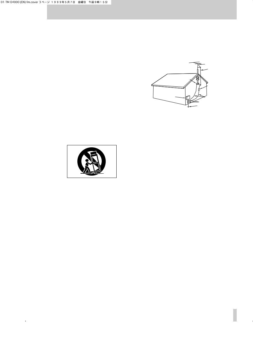
8)Accessories — Do not place this product on an unstable cart, stand, tripod, bracket, or table. The product may fall, causing serious injury to a child or adult, and serious damage to the product. Use only with a cart, stand, tripod, bracket, or table recommended by the manufacturer, or sold with the product. Any mounting of the product should follow the manufacturer’s instructions, and should use a mounting accessory recommended by the manufacturer.
9)A product and cart combination should be moved with care. Quick stops, excessive force, and uneven surfaces may cause the product and cart combination to overturn.
10)Ventilation — Slots and openings in the cabinet are provided for ventilation and to ensure reliable operation of the product and to protect it from overheating, and these openings must not be blocked or covered. The openings should never be blocked by placing the product on a bed, sofa, rug, or other similar surface. This product should not be placed in a built-in installation such as a bookcase or rack unless proper ventilation is provided or the manufacturer’s instructions have been adhered to.
11)Power Sources — This product should be operated only from the type of power source indicated on the marking label. If you are not sure of the type of power supply to your home, consult your product dealer or local power company. For products intended to operate from battery power, or other sources, refer to the operating instructions.
12)Grounding or Polarization — This product may be equipped with a polarized alternating-current line plug (a plug having one blade wider than the other). This plug will fit into the power outlet only one way. This is a safety feature. If you are unable to insert the plug fully into the outlet, try reversing the plug. If the plug should still fail to fit, contact your electrician to replace your obsolete outlet. Do not defeat the safety purpose of the polarized plug.
13)Power-Cord Protection — Power-supply cords should be routed so that they are not likely to be walked on or pinched by items placed upon or against them, paying particular attention to cords at plugs, convenience receptacles, and the point where they exit from the product.
14)Outdoor Antenna Grounding — If an outside antenna or cable system is connected to the product, be sure the antenna or cable system is grounded so as to provide some protection against voltage surges and built-up static charges. Article 810 of the National Electrical Code, ANSI/NFPA 70, provides information with regard to proper grounding of the mast and supporting structure, grounding of the lead-in wire to an antenna discharge unit, size of grounding conductors, location of antenna-discharge unit, connection to grounding electrodes, and requirements for the grounding electrode.
"Note to CATV system installer:
This reminder is provided to call the CATV system installer’s attention to Section 820-40 of the NEC which provides guidelines for proper grounding and, in particular, specifies that the cable ground shall be connected to the grounding system of the building, as close to the point of cable entry as practical.
Example of Antenna Grounding as per
National Electrical Code, ANSI/NFPA 70
|
ANTENNA |
|
LEAD IN |
|
WIRE |
|
GROUND |
|
CLAMP |
|
ANTENNA |
|
DISCHARGE UNIT |
|
(NEC SECTION 810-20) |
ELECTRIC |
|
SERVICE |
GROUNDING CONDUCTORS |
EQUIPMENT |
|
|
(NEC SECTION 810-21) |
|
GROUND CLAMPS |
|
POWER SERVICE GROUNDING |
|
ELECTRODE SYSTEM |
NEC - NATIONAL ELECTRICAL CODE |
(NEC ART 250. PART H) |
|
15)Lightning — For added protection for this product during a lightning storm, or when it is left unattended and unused for long periods of time, unplug it from the wall outlet and disconnect the antenna or cable system. This will prevent damage to the product due to lightning and power-line surges.
16)Power Lines — An outside antenna system should not be located in the vicinity of overhead power lines or other electric light or power circuits, or where it can fall into such power lines or circuits. When installing an outside antenna system, extreme care should be taken to keep from touching such power lines or circuits as contact with them might be fatal.
17)Overloading — Do not overload wall outlets, extension cords, or integral convenience receptacles as this can result in risk of fire or electric shock.
18)Object and Liquid Entry — Never push objects of any kind into this product through openings as they may touch dangerous voltage points or short-out parts that could result in a fire or electric shock. Never spill liquid of any kind on the product.
19)Servicing — Do not attempt to service this product yourself as opening or removing covers may expose you to dangerous voltage or other hazards. Refer all servicing to qualified service personnel.
20)Damage Requiring Service — Unplug this product from the wall outlet and refer servicing to qualified service personnel under the following conditions:
a) when the power-supply cord or plug is damaged.
b) if liquid has been spilled, or objects have fallen into the product. c) if the product has been exposed to rain or water.
d) if the product does not operate normally by following the operating instructions. Adjust only those controls that are covered by the operating instructions as an improper adjustment of other controls may result in damage and will often require extensive work by a qualified technician to restore the product to its normal operation.
e) if the product has been dropped or damaged in any way.
f ) when the product exhibits a distinct change in performance – this indicates a need for service.
21)Replacement Parts — When replacement parts are required, be sure the service technician has used replacement parts specified by the manufacturer or have the same characteristics as the original part.
Unauthorized substitutions may result in fire, electric shock, or other hazards.
22)Safety Check — Upon completion of any service or repairs to this product, ask the service technician to perform safety checks to determine that the product is in proper operating condition.
23)Wall or Ceiling Mounting — The product should be mounted to a wall or ceiling only as recommended by the manufacturer.
24)Heat — The product should be situated away from heat sources such as radiators, heat registers, stoves, or other products (including amplifiers) that produce heat.
3

1 - Introduction
1.1 |
Features ............................................. |
1–1 |
|
1.2 |
About this manual ............................ |
1–1 |
|
|
1.2.1 How this manual is arranged ....................... |
1–2 |
|
|
1, “Introduction” .................................................. |
1–2 |
|
|
2, “Principles of operation” ................................. |
1–2 |
|
|
3, “System setup” ............................................... |
1–2 |
|
|
4, “Module operations” ....................................... |
1–2 |
|
|
5, “Monitoring” .................................................... |
1–2 |
|
|
6, “Surround modes” .......................................... |
1–2 |
|
|
7, “Internal effect processor” .............................. |
1–2 |
|
|
8, “Library functions” ........................................... |
1–2 |
|
|
9, “Machine Control” ........................................... |
1–2 |
|
|
10, “MIDI” ........................................................... |
1–2 |
|
|
11, “Cascade” ..................................................... |
1–2 |
|
|
12, “Front panel” ................................................. |
1–2 |
|
|
13, “Rear panel & connections” .......................... |
1–2 |
|
|
14, “Specifications, etc.” ..................................... |
1–2 |
|
|
“Tutorial–Simple recording session” ................... |
1–2 |
|
1.3 |
Expansion cards ............................... |
1–2 |
|
|
IF-TD4000 .......................................................... |
1–3 |
|
|
IF-AE4000 .......................................................... |
1–3 |
|
|
IF-LP4000 ........................................................... |
1–3 |
|
|
IF-AD4000 .......................................................... |
1–3 |
|
|
1.3.1 Fitting the interface cards ............................. |
1–3 |
|
|
1.3.2 |
Input channel numbering ............................. |
1–4 |
|
1.3.3 |
Output busses .............................................. |
1–4 |
|
1.3.4 |
Direct out ...................................................... |
1–4 |
1.4 |
Word clock issues ............................ |
1–5 |
|
1.5 |
Effects and monitoring ..................... |
1–5 |
|
2 - Principles of operation
2.1 |
User interface .................................... |
2–1 |
|
2.2 |
Road map .......................................... |
2–1 |
|
2.3 |
Using the PODs ................................. |
2–2 |
|
|
2.3.1 |
Selecting screens ......................................... |
2–2 |
|
2.3.2 |
Navigation in screens ................................... |
2–3 |
|
2.3.3 Using the JOG dial ....................................... |
2–3 |
|
|
2.3.4 One channel or one parameter? .................. |
2–3 |
|
|
2.3.5 |
Selecting channels ....................................... |
2–4 |
2.4 |
Fader layers ....................................... |
2–4 |
|
|
2.4.1 Turning fader motors on and off ................... |
2–5 |
|
|
2.4.2 Physical and logical faders .......................... |
2–5 |
|
3 - System setup
3.1 |
I/O setup ............................................ |
3–1 |
|
|
3.1.1 |
STEREO OUT settings ................................ |
3–1 |
|
3.1.2 |
Consumer options ........................................ |
3–2 |
|
3.1.3 Word length and dithering ............................ |
3–2 |
|
3.2 |
CLOCK setup .................................... |
3–2 |
|
|
3.2.1 |
Selecting clock frequencies ......................... |
3–3 |
|
3.2.2 |
Clock check .................................................. |
3–4 |
|
3.2.3 |
Clock settings (other) ................................... |
3–4 |
|
3.2.4 |
Clock tolerance ............................................ |
3–4 |
3.3 |
Option setup ...................................... |
3–4 |
|
|
3.3.1 |
Location display mode ................................. |
3–5 |
|
3.3.2 |
Timecode source ......................................... |
3–5 |
|
3.3.3 |
Preferences .................................................. |
3–5 |
|
3.3.4 |
Fader select ................................................. |
3–5 |
|
3.3.5 |
Select MODULE return ................................ |
3–5 |
|
3.3.6 |
Select link ..................................................... |
3–5 |
Table of Contents
|
3.3.7 |
Dial edit ........................................................ |
3–5 |
|
3.3.8 |
Automation fader inhibit ................................ |
3–5 |
|
3.3.9 |
Balance level ................................................ |
3–5 |
|
3.3.10 |
Oscillator ...................................................... |
3–5 |
|
3.3.11 |
Meter ballistics .............................................. |
3–5 |
4 - Module operations |
|
||
4.1 |
Module features and control ............ |
4–1 |
|
|
4.1.1 |
Stereo out module ........................................ |
4–1 |
|
4.1.2 |
Control of module parameters ...................... |
4–1 |
4.2 |
Stereo linking ..................................... |
4–2 |
|
|
4.2.1 |
Using the ST LINK key to link channels ....... |
4–2 |
|
4.2.2 |
Using the SEL keys to link channels ............ |
4–2 |
4.3 |
Equalization ....................................... |
4–3 |
|
4.4 |
Channel-to-buss assignments ......... |
4–3 |
|
|
4.4.1 |
Using the MODULE screen for buss |
|
|
|
assignment ................................................... |
4–3 |
4.4.2Using the ASSIGN key for buss assignment 4–4
4.5 Aux sends .......................................... |
4–4 |
4.5.1Using the MODULE screen to set send
levels ............................................................ |
4–4 |
4.5.2 Using AUX keys to set send levels ............... |
4–4 |
AUX Fader control .............................................. |
4–5 |
Stereo linking and AUX sends ............................ |
4–5 |
4.6 Dynamics processor settings .......... |
4–5 |
4.6.1 Assigning a processor to a module .............. |
4–6 |
4.6.2Using the MODULE key to make dynamics
processor settings ........................................ |
4–6 |
4.6.3Using the DYNAMICS key to make dynamics
|
|
processor settings ........................................ |
4–6 |
4.6.4 |
Compressor/limiter settings .......................... |
4–6 |
|
4.6.5 |
Gate settings ................................................ |
4–7 |
|
4.6.6 |
Linked channels ........................................... |
4–7 |
|
4.7 |
Pan and balance ................................ |
4–7 |
|
4.7.1 |
Using the MODULE key to set pan and |
|
|
|
|
balance ......................................................... |
4–7 |
|
Mono modules .................................................... |
4–7 |
|
|
Stereo modules .................................................. |
4–7 |
|
4.7.2 |
Using the PAN/BAL key ............................... |
4–8 |
|
4.8 |
Pad and phase(Φ) .............................. |
4–8 |
|
4.8.1 |
Using the MODULE screen .......................... |
4–8 |
|
4.8.2 |
Using the PAD/phase key ............................ |
4–8 |
|
4.9 |
Fader and cut groups ........................ |
4–9 |
|
4.9.1 |
Making group settings .................................. |
4–9 |
|
4.9.2 |
Clearing group settings ................................ |
4–9 |
|
4.10 |
Checking fader and cut status ......... |
4–9 |
|
4.10.1 |
Resetting faders to 0 dB ............................... |
4–10 |
|
4.10.2 |
Buss and Aux send metering ....................... |
4–10 |
|
4.11 |
Buss delay ......................................... |
4–10 |
|
4.11.1 |
Global delay setting ...................................... |
4–11 |
|
4.12 |
MODULE screen (miscellaneous) .... |
4–11 |
|
4.12.1 |
Meter pickoff point ........................................ |
4–11 |
|
4.12.2 |
Other information .......................................... |
4–11 |
|
4.13 |
Soloing ............................................... |
4–11 |
|
5 - Monitoring
5.1 CR and STUDIO ................................. |
5–13 |
|
5.1.1 |
Monitor sources ............................................ |
5–13 |
5.1.2 |
Adjusting volume .......................................... |
5–13 |
5.1.3 |
Talkback ....................................................... |
5–13 |
5.1.4 |
Near-field monitors ....................................... |
5–13 |
Table of Contents–i

Table of Contents
5.2 |
Meters ................................................ |
5–13 |
|
5.3 |
2-track monitoring ............................ |
5–14 |
|
5.4 |
SOLO .................................................. |
5–14 |
|
|
5.4.1 |
Inplace solo defeat ....................................... |
5–14 |
|
5.4.2 |
Solo mode .................................................... |
5–14 |
|
5.4.3 |
PFL level ...................................................... |
5–15 |
|
5.4.4 To clear all soloed channels ......................... |
5–15 |
|
6 - Surround modes
6.1 |
Selecting a surround mode .............. |
6–1 |
|
|
6.1.1 Selecting a buss pattern ............................... |
6–1 |
|
6.2 |
Monitoring issues ............................. |
6–2 |
|
6.3 |
Buss delay ......................................... |
6–2 |
|
6.4 |
Modules in the surround mix ........... |
6–2 |
|
|
6.4.1 |
Assigning modules ....................................... |
6–2 |
|
6.4.2 |
“Pan” controls ............................................... |
6–3 |
7 - Internal effect processor
7.1 |
Routing the processor ...................... |
7–1 |
|
|
7.1.1 |
Effect processor feed ................................... |
7–1 |
|
7.1.2 |
Processor input mode .................................. |
7–1 |
|
7.1.3 Effect processor input level .......................... |
7–1 |
|
|
7.1.4 |
Effect processor return ................................. |
7–1 |
7.2 |
Effect types ....................................... |
7–2 |
|
|
7.2.1 Selecting a basic effect type ......................... |
7–2 |
|
|
7.2.2 Editing a recalled effect ................................ |
7–2 |
|
|
7.2.3 Storing an edited effect ................................ |
7–3 |
|
7.3 |
Preset effects .................................... |
7–4 |
|
8 - Library functions
8.1 |
Snapshot memories ......................... |
8–1 |
|
|
8.1.1 |
Snapshot 00 ................................................. |
8–1 |
|
8.1.2 |
Recalling a snapshot .................................... |
8–2 |
|
8.1.3 |
Storing a snapshot ....................................... |
8–2 |
|
8.1.4 |
Copying a snapshot ...................................... |
8–2 |
|
8.1.5 |
Naming a snapshot ...................................... |
8–2 |
|
8.1.6 MIDI dumping and loading of snapshot |
|
|
|
|
library entries ................................................ |
8–3 |
8.2 |
Other libraries ................................... |
8–4 |
|
|
8.2.1 |
Effect type abbreviations .............................. |
8–5 |
|
8.2.2 Recalling a library entry ................................ |
8–6 |
|
|
8.2.3 Storing a library entry ................................... |
8–6 |
|
|
8.2.4 Copying a library entry ................................. |
8–6 |
|
|
8.2.5 Naming a library entry .................................. |
8–6 |
|
|
8.2.6 Storing and recalling library entries using |
|
|
|
|
MIDI .............................................................. |
8–6 |
8.3 |
Preset library entries ........................ |
8–7 |
|
|
8.3.1 |
EQ presets ................................................... |
8–7 |
|
8.3.2 |
Dynamics processor presets ........................ |
8–8 |
9 - Machine Control
9.1 Selecting devices for control ........... |
9–1 |
9.1.1 Deleting devices from the list ....................... |
9–1 |
9.1.2 Auto-detection of devices ............................. |
9–1 |
9.1.3 Selecting the control type for the devices ..... |
9–2 |
PORT .................................................................. |
9–2 |
DEVICE .............................................................. |
9–2 |
ID ........................................................................ |
9–2 |
CHASE ............................................................... |
9–2 |
SCR .................................................................... |
9–2 |
Table of Contents–ii
TRA and REC ..................................................... |
9–2 |
|
9.1.4 |
Machine Control mapping memories ............ |
9–3 |
9.1.5 |
Showing current Machine Control |
|
|
mappings ...................................................... |
9–4 |
9.1.6Automatically creating a list of machine
|
|
control mapping memories ........................... |
9–4 |
9.2 |
General parameters ........................... |
9–4 |
|
|
9.2.1 |
Edit Frames .................................................. |
9–4 |
|
9.2.2 |
Play Mode ..................................................... |
9–5 |
|
AUTO .................................................................. |
9–5 |
|
|
DEFERRED ........................................................ |
9–5 |
|
|
IMMEDIATE ........................................................ |
9–5 |
|
|
9.2.3 |
Cueing Mode ................................................ |
9–5 |
|
9.2.4 |
Locate Preroll ............................................... |
9–5 |
9.3 |
Location memories ............................ |
9–5 |
|
|
9.3.1 Selecting the location point display .............. |
9–5 |
|
|
9.3.2 Storing a location memory “on the fly” .......... |
9–6 |
|
9.3.3Manually entering and editing a location
|
memory ......................................................... |
9–6 |
9.3.4 Location to a location memory ...................... |
9–6 |
|
9.3.5 Viewing a list of location memories .............. |
9–6 |
|
9.3.6 |
Manual location ............................................ |
9–7 |
9.3.7 |
Repeat play .................................................. |
9–7 |
9.3.8 |
Auto punch operations .................................. |
9–7 |
9.3.9 ALL INPUT and AUTO MON ........................ |
9–7 |
|
9.4 Notes on individual devices ............. |
9–7 |
|
9.4.1 |
MIDI timecode generator .............................. |
9–7 |
9.4.2 |
DTRS devices ............................................... |
9–8 |
9.4.3 |
8mm DTRS ................................................... |
9–8 |
9.4.4 |
ADAT devices ............................................... |
9–8 |
9.4.5 MIDI Controllers and MIDI Faders ................ |
9–8 |
|
9.4.6 |
JLC BB3 ....................................................... |
9–9 |
9.4.7 |
MMC devices ................................................ |
9–9 |
9.4.8 |
Cascade slave .............................................. |
9–9 |
10 - MIDI
10.1 |
MIDI settings .................................... |
10–1 |
|
|
Basic Channel ................................................... |
10–1 |
|
|
OMNI Receive ................................................... |
10–1 |
|
|
RESET .............................................................. |
10–1 |
|
|
Output Active Sensing ...................................... |
10–1 |
|
|
Output MTC when slaved ................................. |
10–1 |
|
|
Merge In Æ Out ................................................ |
10–1 |
|
10.2 |
MIDI data dumps .............................. |
10–2 |
|
10.2.1 |
Receiving bulk data .................................... |
10–2 |
|
10.2.2 Transferring data between two |
|
||
|
|
TM-D4000 units .......................................... |
10–2 |
10.3 |
Program Change commands .......... |
10–2 |
|
10.3.1 Setting the Program Change tables ........... |
10–3 |
||
10.4 |
MIDI controllers ............................... |
10–3 |
|
10.5 |
MIDI Faders ...................................... |
10–4 |
|
10.6 |
Sequenced mixing ........................... |
10–4 |
|
10.7 |
MIDI System Exclusive data |
|
|
|
formats ............................................. |
10–4 |
|
10.7.1 |
Device Inquiry ............................................. |
10–4 |
|
10.7.2 |
Master Volume ........................................... |
10–5 |
|
10.7.3 Other System Exclusive messages ............ |
10–5 |
||
10.8 |
Updating the system software ....... |
10–5 |
|
10.8.1 Viewing the current version number ........... |
10–5 |
||
10.8.2 |
Equipment needed ..................................... |
10–5 |
|
10.8.3 |
Connections ................................................ |
10–5 |
|
10.8.4 |
Preparing to upgrade .................................. |
10–6 |
|

10.8.5 |
Upgrading .................................................. |
10–6 |
10.8.6 Notes on the upgrade process ................... |
10–6 |
|
10.8.7 |
A note on using sequencer programs ........ |
10–6 |
10.9 MIDI Implementation Chart ............ |
10–6 |
|
11 - Cascade
11.1 |
Cascade connections ..................... |
11–1 |
|
11.1.1 Selecting busses for cascade .................... |
11–2 |
||
11.1.2 Word sync in a cascade ............................. |
11–3 |
||
11.2 |
Using the cascade .......................... |
11–3 |
|
11.2.1 |
Level settings ............................................. |
11–3 |
|
11.2.2 |
Option settings ........................................... |
11–3 |
|
11.2.3 |
Automation settings ................................... |
11–3 |
|
11.2.4 |
Monitoring .................................................. |
11–3 |
|
11.2.5 |
Soloing (PFL) ............................................. |
11–3 |
|
11.2.6 |
Soloing (IPS) .............................................. |
11–4 |
|
11.2.7 |
SOLO all clear ............................................ |
11–4 |
|
11.2.8 |
Snapshot library functions .......................... |
11–4 |
|
11.2.9 Talkback in the cascade ............................ |
11–4 |
||
12 - Front panel
12.1 |
System controls, etc. ...................... |
12–1 |
[1] |
Clock and Fs indicators .............................. |
12–1 |
[2] |
Automation control ..................................... |
12–1 |
[3] |
LAYER STATUS keys and indicators ........ |
12–1 |
[4] |
Library ........................................................ |
12–1 |
[5] |
Configuration keys ..................................... |
12–2 |
12.2 |
Mixing keys ..................................... |
12–2 |
[6] |
FADER POSITION key .............................. |
12–2 |
[7] |
AUX 1 through AUX 6 keys ........................ |
12–2 |
[8] |
PAN/BAL–SURROUND key ...................... |
12–2 |
[9] |
MODULE key ............................................. |
12–2 |
[10] |
ASSIGN key ............................................... |
12–3 |
[11] |
DYNAMICS key ......................................... |
12–3 |
[12] |
PAD/Φ ........................................................ |
12 3 |
[13] |
EFFECT key .............................................. |
12–3 |
12.3 Display and POD s .......................... |
12–3 |
|
[14] |
Display screen ........................................... |
12–3 |
[15] |
PODs ......................................................... |
12–3 |
[16] |
ROW CURSOR keys ................................. |
12–3 |
[17] |
Contrast control () ...................................... |
12–3 |
12.4 |
Module control keys ....................... |
12–3 |
[18] |
EQ key ....................................................... |
12–3 |
[19] |
DYNAMICS key ......................................... |
12–3 |
[20] |
BUSS ASSIGN keys .................................. |
12–3 |
12.5 Monitor control keys and meters .. |
12–3 |
|
[21] |
Meters ........................................................ |
12–3 |
[22] |
Monitor select keys and indicators ............. |
12–4 |
[23] |
PFL and IN PLACE indicators .................... |
12–4 |
[24]TO SLATE and TO AUX 1-2 keys and
indicators .................................................... |
12–4 |
12.6 Chs1–16,17–32,Aux&busssendmasters
12–4
[25] |
REC key and indicator (modules 1–16) ..... |
12–4 |
[26] |
SEL key and indicator ................................ |
12–4 |
[27]SOLO key and indicator (mono input
|
modules and ST IN modules) .................... |
12–4 |
[28] CUT key and indicator ............................... |
12–4 |
|
[29] |
READ. WRITE, UPDATE indicators .......... |
12–5 |
[30] |
Layered faders ........................................... |
12–5 |
Table of Contents
12.7 Stereo input and stereo masters ... 12–5
[31] ST IN & 2 faders ......................................... |
12–5 |
|
[32] |
STEREO OUT fader ................................... |
12–5 |
[33] |
ALL SAFE key ............................................ |
12–5 |
12.8 |
Machine control ............................... |
12–5 |
[34] |
TC/LOC indicators ...................................... |
12–5 |
[35] MDM LOCK indicators and time counter .... |
12–6 |
|
[36] Punch keys and indicators ......................... |
12–6 |
|
[37] |
ALL INPUT key ........................................... |
12–6 |
[38] |
AUTO MON ................................................ |
12–6 |
[39] |
MACHINE SELECT .................................... |
12–6 |
[40] REPEAT 8-9 key and indicator ................... |
12–6 |
|
[41]MEMO, MANUAL LOCATE, EDIT, DIRECT LOCATE, CLR keys and indicators and
|
numeric keypad .......................................... |
12–6 |
[42] |
ENT key ...................................................... |
12–6 |
[43] Transport keys and indicators .................... |
12–6 |
|
12.9 |
Data entry section ........................... |
12–6 |
[44]JOG/SHUTTLE key, indicator, dial
|
and wheel ................................................... |
12–6 |
[45] |
ENTER key ................................................. |
12–6 |
[46] |
Cursor keys ................................................ |
12–6 |
13 - Rear panel & connections
13.1 Analog inputs .................................. |
13–1 |
[47] MIC input (channels 1–8) ........................... |
13–1 |
[48] LINE IN (BAL) input (channels 1–8) ........... |
13–1 |
[49] INSERT connector (channels 1–8) ............. |
13–1 |
[50] LINE switch (channels 1–8) ........................ |
13–1 |
[51] PAD switch (channels 1–8) ........................ |
13–1 |
[52]TRIM control (channels 1–8 and ST RTN
|
1 and 2) ...................................................... |
13–1 |
[53] O/L indicator (channels 1–8) ...................... |
13–1 |
|
[54] PHANTOM (+48V) 1–4 & 5–8 switches ..... |
13–2 |
|
[55] L (MONO) & R inputs (ST IN 1 & 2) ........... |
13–2 |
|
13.2 |
Analog outputs, etc. ........................ |
13–2 |
[56] |
AUX OUTPUTS .......................................... |
13–2 |
[57] |
2TR RTN (BALANCED) ............................. |
13–2 |
[58] |
2TR RTN (UNBALANCED) ........................ |
13–2 |
[59] |
STEREO OUTPUTS (UNBALANCED) ...... |
13–2 |
[60] |
STEREO OUTPUTS (BALANCED) ............ |
13–2 |
[61] MONITOR OUTPUTS (CR and STUDIO) .. |
13–2 |
|
13.3 |
Talkback ........................................... |
13–2 |
[62] 2TR RTN 1/2 switch ................................... |
13–3 |
|
[63] |
CR level ...................................................... |
13–3 |
[64] DIM key and indicator ................................. |
13–3 |
|
[65] |
STUDIO/PHONE Slevel ............................. |
13–3 |
[66] |
MONO key .................................................. |
13–3 |
[67] |
TB LEVEL control ....................................... |
13–3 |
[68] |
STUDIO key ............................................... |
13–3 |
[69] |
PHONES jack ............................................. |
13–3 |
[70] |
Talkback microphone (unlabeled) .............. |
13–3 |
13.4 |
Digital I/O .......................................... |
13–3 |
[71] |
DIGITAL OUTPUT (XLR-type) ................... |
13–3 |
[72] |
DIGITAL OUTPUT (RCA) ........................... |
13–3 |
[73] D IN 2 (RCA) .............................................. |
13–3 |
|
[74] |
D IN 1(XLR-type) ........................................ |
13–3 |
13.5 |
Other connections ........................... |
13–4 |
[75] |
POWER switch ........................................... |
13–4 |
[76] WORD SYNC OUT connector .................... |
13–4 |
|
[77] WORD SYNC IN connector and switch ...... |
13–4 |
|
[78] |
CASCADE IN and CASCADE OUT .......... |
13–4 |
Table of Contents–iii

Table of Contents
[79] |
TO METER ................................................. |
13–4 |
[80] |
RS-422 ....................................................... |
13–4 |
[81] |
TO HOST ................................................... |
13–4 |
[82] MIDI IN, OUT and THRU ............................ |
13–4 |
|
[83] |
TC IN .......................................................... |
13–4 |
14 - Specifications, etc.
14.1 |
Analog audio I/O ............................. |
14–1 |
14.2 |
Digital audio I/O .............................. |
14–1 |
14.2.1 Sampling frequency .................................... |
14–1 |
|
14.3 |
Other I/O .......................................... |
14–1 |
14.4 |
Analog performance ....................... |
14–2 |
14.4.1MIC/LINE channel inputs (measured with STEREO OUTPUTS) 14–2
14.4.2STEREO IN 1 and 2 (measured with
|
STEREO OUTPUTS) ................................. |
14–2 |
14.4.3 |
2TR RTN1 input ......................................... |
14–2 |
14.4.4 |
2TR RTN2 input ......................................... |
14–2 |
14.4.5 |
STEREO outputs (XLR) ............................. |
14–2 |
14.4.6 |
STEREO outputs (RCA) ............................. |
14–2 |
14.4.7 |
AUX 1–6 outputs ........................................ |
14–2 |
14.4.8 |
CR outputs ................................................. |
14–2 |
14.4.9 |
STUDIO outputs ......................................... |
14–2 |
14.4.10 PHONES output ......................................... |
14–2 |
|
14.4.11 Overall system performance ...................... |
14–2 |
|
14.5 Physical specifications .................. |
14–3 |
|
14.6 Error and warning messages ........ |
14–3 |
|
14.6.1 |
Clock and synchronization ......................... |
14–3 |
14.6.2 |
General ....................................................... |
14–3 |
14.6.3 |
Automation setup ....................................... |
14–4 |
14.6.4 |
Machine control .......................................... |
14–4 |
14.6.5 |
Snapshot library ......................................... |
14–4 |
14.6.6 |
Dynamics library ......................................... |
14–4 |
14.6.7 |
EQ library ................................................... |
14–5 |
14.6.8 |
Effect library ............................................... |
14–5 |
14.6.9 Stereo link (using SEL keys) ...................... |
14–5 |
|
14.6.10 Computer communications (automation) .... |
14–5 |
|
14.6.11 MIDI ............................................................ |
14–6 |
|
14.6.12 Fatal System Errors .................................... |
14–6 |
|
14.7 |
Block diagram .................................. |
14–7 |
14.8 |
Screen details .................................. |
14–8 |
Tutorial–Simple recording session
T1 |
Connections ....................................... |
T–1 |
T2 |
Setup .................................................. |
T–2 |
T3 |
Basic Routing .................................... |
T–3 |
T4 |
Gain Structure.................................... |
T–4 |
T5 |
Adding Effects ................................... |
T–4 |
T6 |
Transport Control .............................. |
T–6 |
T7 |
Gain Structure Revisited ................ |
T–6 |
|
Adding Channel Dynamics & EQ ................ |
T–6 |
T8 |
Snapshots ......................................... |
T–7 |
T9 |
Data Backup ...................................... |
T–8 |
Table of Contents–iv

The TM-D4000 digital mixing console is designed to provide you with superlative audio quality in today’s digital audio recording environment, as well as ease of use and e xibility to meet changing needs.
This Reference Manual is not intended to be read from cover to cover, but we do suggest that you make yourself familiar with the contents of this section as well as the structure of this manual, so that you can find answers to questions when you need them.
If you learn a little about the key features and principles of operation now, before you start to use the TM-D4000 it will save you time and trouble later on.
1.1 Features
The TM-D4000 includes many advanced features, including:
•modular construction, allowing input and output channels to be added in different congurations up to 32 inputs and outputs
•the sixteen long-throw motorized “channel” faders are “layered”, allowing control of up to 32 mono inputs (which may be “ganged” in stereo pairs), eight buss sends and six aux sends in a compact package
•in addition to the sixteen faders mentioned above, three dedicated motorized long-throw faders are used for two pairs of stereo inputs and the stereo out buss
•the TASCAM TDIF-1 digital audio format and other popular digital audio formats, as well as high-quality A/D and D/A conversion, are supported through modular expansion,
•all A/D and D/A convertors, including the nal stereo mix, work at up to 24-bit resolution
•digital I/O is also available at up to 24-bit resolution
•eight output busses and six auxiliary sends
•all popular surround formats, as well as stereo, are supported for nal mixdo wn
•expansion with other TM-D4000 consoles using dedicated cascade cables for summing of busses and Aux sends
•integral effects processor, allowing self-contained operation when necessary
•both 44.1 kHz and 48 kHz sampling frequencies are supported, with e xible clock conguration
•each input channel is equipped with 4-band fullyparametric equalization and a dynamics processor
1 - Introduction
•eight integral high-quality microphone ampliers, with switchable phantom powering, as well as two analog stereo inputs with dedicated faders
•eight fader groups and eight cut groups for e xibility and ease in the mixdown process
•the capability of acting as a remote controller for a wide variety of devices
•synchronization and MIDI timecode generation facilities, allowing location of connected recorders, etc. and integration with the DTRS tape system
•full C-R and studio monitoring facilities are provided, along with an integral talkback microphone and master bargraph meters
•graphical user interface featuring a backlit LCD display with a flexible POD based interface
•library facilities for snapshot mix settings, fre- quently-used EQ settings, effect settings, dynamics processor settings, etc.
•MIDI control allows dynamic control of parameters through MIDI messages, so mix events can be recorded on MIDI for replay, as well as snapshot recall being linked to Program Change messages
•personal computers connected to the TM-D4000 can run automation software, allowing full realtime control of almost all mix parameters
•an optional MU-4000 meter bridge unit provides channel and master metering facilities through LED bargraph displays which are switchable in “layers”
1.2 About this manual
Please note the following typographical and other conventions used in this manual:
•Physical “push” controls of the TM-D4000 are referred to as “keys”.
•“Push” controls which are shown and used on the screen are referred to as “buttons”.
•The names of keys and other connectors and controls of the TM-D4000 are given in the following typeface: ROW CURSOR.
•The names of on-screen buttons and other onscreen features, titles and prompts, etc. are given in
the following typeface:SNAPSHOT LIB |
. |
•The names of any physical keys, connectors and controls of other devices are given in the following typeface: REMOTE IN.
•“Warnings” give advice regarding a possible hazard to equipment or personnel.
1–1

1 - Introduction—Expansion cards
•“Notes” provide additional information which requires special attention.
1.2.1 How this manual is arranged
We feel that the first five sections of this manual are "required reading". If you take the trouble to read through these sections, you will have a good basic understanding of the way in which you can get the best out of the TM-D4000. Even if you are familiar with the operation of mixers and digital mixers, and even if you never usually read instruction manuals, we suggest that you read these sections. They will provide useful background information for you as you use the TM-D4000.
The other sections are more in the nature of background reference, and contain information that you may not need for everyday working.
Lastly, a tutorial section is provided that allows you (or a new user of the TM-D4000) to become familiar with the working of the TM-D4000.
1, “Introduction” : This section. It provides an overview of the TM-D4000, its operational features, and the manual.
2, “Principles of operation” : Contains basic information on the layout and the special features of the TM-D4000 (fader layers, user interface features, etc.).
3, “System setup” : Before using the TMD4000, there are certain issues concerned with word (sync) clock timing, etc. This section should be read before you start integrating the TM-D4000 into your setup.
4, “Module operations” : This may be regarded as the "heart" of this manual—it contains details of the everyday operations you perform with any mixing console; for example, equalization, Aux sends, buss routing, etc.
5, “Monitoring” : Explains the principles of monitoring durinng multitracking annd mixdown, and solo operations, etc. using the TM-D4000.
6, “Surround modes” : The TM-D4000 is capable of mixing a a number of different surround formats. This section explains how to use this mixer for surround purposes.
7, “Internal effect processor” : This section explains how to use and set the internal effect processor of the TM-D4000.
8, “Library functions” : In addition to effect processor settings, complete mixer snapshots, equalization settings, and dynamics processor settings can be stored and recalled for convenience. These "library" functions are described in this section.
9, “Machine Control” : The TM-D4000 can act as a remote control unit for a wide variety of external devices, and provides MIDI timecode synchronization facilities. This section provides a guide to these facilities.
10, “MIDI” : This section gives a description of the MIDI-related features of the TM-D4000.
11, “Cascade” : This section describes the way in which a number of TM-D4000 units can be linked together in a “cascade” to form a larger mixing unit.
12, “Front panel” : Provides a brief description of the front panel features of the TM-D4000.
13, “Rear panel & connections” : Provides a brief description of the rear panel connectors, etc. and the connections to be made to and from the TMD4000 and other units.
14, “Specifications, etc.” : Specifications, and a list of error messages, as well as all the configuration screens available, and a block diagram of the TM-D4000.
“Tutorial–Simple recording session” :
This provides a simple recording session using an analog source (CD player) recording to a DTRS unit, and mixing down to DAT. We suggest that you work through this (about 1 hour) to familiarize yourself with the way in which the TM-D4000 works. This tutorial may be removed from the main manual binder and stored seperately, if desired.
There is also an index, which should allow you to find the answers to any questions relatively easily.
In addition to this manual, the documentation for the automation software is provided seperately, as is the documentation for the expansion cards (see below) and the optional MU-4000 meter bridge unit.
1.3 Expansion cards
You must decide on the system that you will be using with your TM-D4000 and configure it appropriately.
There are three slots available for expansion cards. Without any expansion cards fitted in these slots, the TM-D4000 is only capable of accepting analog sig-
1–2

1 - Introduction—Expansion cards
nals through the eight mono analog inputs, the two stereo analog inputs and the two stereo digital inputs, and outputting them to the stereo buss.
These interface cards are easy to install, and it is therefore possible to keep a stock of different interface cards, allowing the TM-D4000 to be used in different ways as needs dictate on different occasions.
Without any interface cards tted, the TM-D4000 provides eight monaural analog inputs and two pairs of stereo analog inputs. These may be mixed to a stereo pair of outputs, in either digital or analog format.
IF-TD4000 : This interface card provides eight channels of digital input/output in TDIF-1 format, allowing devices such as the DTRS series to be connected. In addition to the digital audio, this interface card also provides a REMOTE OUT connection, allowing synchronization and control of the remote DTRS recorder.
Note that when connecting a chain of DTRS units using more than one IF-TD4000 card, etc. only one of the DTRS units (the master unit) should be connected directly to the TM-D4000 with the REMOTE connection. The other units should be “daisychained” to the rst master unit.
IF-AE4000 : This interface card provides eight channels of digital audio input/output in 1992-3AES/ EBU professional format. The signals are connected through a 25-pin ’D’-sub connector, and so a suitable cable must be used in order to connect the AES/EBU devices.
IF-LP4000 : This interface card provides eight channels of digital audio input/output in adat™ format. The links to external devices are made through optical “lightpipe” connections, allowing the TMD4000 to be connected to any device supporting such a compatible interface. A 9-pin ’D’-sub SYNC OUT connector is also provided, allowing full remote control of and word clock synchronization to the adat device.
Note that when connecting a chain of adat units using more than one IF-LP4000 card, etc. only one of the DTRS units (the master unit) should be connected directly to the TM-D4000 with the SYNC OUT con-
nection. The other units should be “daisy-chained” to the master unit.
Also note than when an adat device is connected to the IF-LP4000, both the IN and OUT connections must be made, and they must be made to the same unit to ensure clock stability across the system.
IF-AD4000 : This interface card provides eight channels of balanced analog input/output at professional (+4 dBu) levels. All conversion is carried out at 24 bits of resolution. The signals are connected through a 25-pin connector, and a suitable cable will be necessary to connect the external analog devices.
1.3.1Fitting the interface cards
1Turn off the TM-D4000 and disconnect it from the power supply. Disconnect all other equipment connected to it.
WARNING
The above step is most important. If you do not do this, there is a risk that you may cause damage to the TM-D4000 as well as other equipment.
2 Use the screwdriver to remove the blanking panel from the slot into which you will t the interface card. Keep the three retaining screws in a safe place.
We suggest that you start from the top slot (slot 1) and work downwards. Take care, if you are removing a previously-tted inter - face card, that you are removing the retaining screws, and not the smaller screws which x the card to the r ear plate . Also, if you are removing a previously-tted card, use the binding posts on the rear plate to help remove the card.
3 Remove the interface card from the antistatic protective bag.
1–3
1 - Introduction—Expansion cards
4Hold the card by the edges, and insert it, component side upwards, into the slot.
5Locate the card into the connector inside the TM-D4000. Push the card firmly, without forcing, so that the connector grips the end of the card. A new TM-D4000 and/or new card may be a little stiff. Make sure that the card is pushed as far as it will go (so that the card rear connector plate touches the rear panel of the TM-D4000).
6Use the three blanking plate screws to attach the rear panel of the interface card to the rear panel of the TM-D4000.
Repeat this process for all the interface cards that you are fitting.
When removing a card, unscrew the three retaining screws and use the “pull posts” on the rear panel of the card to remove it from the TM-D4000.
There are no rules governing which interface cards may be fitted in any of the three slots—any interface card may be fitted in any expansion slot. However, the following points should be noted.
1.3.2 Input channel numbering
Regardless of the type of interface card fitted, and the expansion slots in which any cards are fitted, the numbering of the input channels is always as follows:
|
|
Channel number |
Slot |
|
|
|
|
1 |
– 8 |
Integral analog inputs |
|
|
|
|
|
9 |
– 16 |
Slot 1 inputs |
|
|
|
||
17 – 24 |
Slot 2 inputs |
||
|
|
||
25 – 32 |
Slot 3 inputs |
||
|
|
|
|
These assignments are fixed, and cannot be changed, except that channels 5 through 8 and 13 through 16 can be assigned to the digital inputs (SPDIF or AES/ EBU).
It is important to note that there are no dedicated tape return channels. Furthermore, because of this, every channel, no matter what its current signal source, is provided with the same full facilities of equalization, dynamic processing, etc., and all channels may be routed to the output busses in an identical manner (direct outs are only possible for input channels 1 through 16, though).
1.3.3 Output busses
All eight output busses are routed simultaneously in parallel to the appropriately-numbered outputs of all three slots (or as many as are filled with expansion cards). If all three slots are filled, output buss 1 is therefore output to output channel 1 of the cards in slot 1, slot 2 and slot 3.
It is therefore possible to record up to 24 tracks simultaneously, but when the output busses only are used, only eight different signals are output. If, for instance, a 24-track recorder is connected to the TMD4000 using three IF-AE4000 cards, the signal of output buss 3 will be recorded on tracks 3, 11 and 19, for example.
However, you can use the “direct out” function of input channels 1 through 16, which will allow simultaneous recording of these sixteen inputs to output busses 17 through 32 (slots 2 and 3), overriding any signals which have been taken from the output busses.
At the same time, any inputs from slots 2 and 3 (channels 17 through 32) can be routed through the output busses, which will be output through slot 1 (outputs 1 through 8).
Before you start recording, make sure that you have the correct interface cards for your setup, so that you can interface the TM-D4000 to the other equipment in your setup.
1.3.4 Direct out
As explained later in this manual, the signals from input channels 1 through 8 (the integral analog inputs) and channels 9 through 16 (the first expansion slot) can be assigned to be sent as direct out, rather than to an output buss.
In this case, to determine the number of the output channel, add 16 to the input channel. Input channel 1 is therefore routed to output channel 17 (the first channel in the second interface slot), input channel 9 to output channel 25 (the first channel in the third interface slot) etc. If no interface cards are fitted in
1–4

1 - Introduction—Word clock issues
the slots, the input signal selected for direct output will not be output from the TM-D4000.
1.4 Word clock issues
The “word clock” in a digital audio system is the timing information that enables the digital audio samples in a system to be synchronized between the different devices. It is completely unconnected with timecode clocks, etc.
There must be one, and only one, word clock master device in a digital audio system. The TM-D4000 is capable of acting as a word clock master or as a slave.
WARNING
There should be one, and only one, word clock in a setup. Multiple word clocks in a setup may result in noise. which can damage monitoring equipment (speakers and amplifiers).
Check with the other equipment that you are using to see whether it can be a master or slave, and work out which device will be your word clock master. If the TM-D4000 is to be a word clock slave in your system, it can accept word clocks from the following sources:
•Any of the slots which are occupied by a digital interface card (either TDIF-1, adat, or AES/EBU). In the latter case, any of the four stereo signal pairs that make up the IF-AE4000 are individually selectable as word clock sources).
•The digital inputs D-IN1 and D-IN2.
•If more than one TM-D4000 is being cascaded, the clock source on a cascaded TM-D4000 will always be the cascade source. The “head” of the cascade chain can select its clock from any available source.
•A word clock signal, received at the dedicated word clock input on the rear panel.
The clock can be at 44.1 kHz or 48 kHz, with some variation possible for varispeed, etc. at ±6%. See 3, “System setup” for details of word clock selection.
1.5 Effects and monitoring
The TM-D4000 has six auxiliary sends (Aux sends). These may be used for cue purposes, for effect sends, or a mixture of these purposes.
In addition, there is a high-quality stereo digital effect processor built into the TM-D4000, and this may be used in addition to external effects. The internal processor can be fed from either the first or last pair of Aux sends, and the stereo output from the processor can be returned to the second stereo pair of channels.
Typically, the six AUX OUTPUT 1/4-inch jacks are used for feeding external effect units, etc. on mixdown, but some of them may be used as studio cue feeds, allowing different sub-mixes to be built up for different monitoring mixes. Since the built-in talkback microphone can be sent to the Aux 1 and 2 busses (as well as being slated), it is suggested that Aux 1 and 2 are used for cueing the in-studio talent.
Though there are no dedicated effect returns, any of the analog inputs can be used for analog effect returns, and the stereo inputs may also be used for this purpose.
Additionally, the two digital stereo inputs can be used as input sources for two of the following channel pairs: 5–6, 7–8, 13–14 or 15–16.
There are two sets of outputs suitable for feeding the control room and studio monitoring systems (as well as a headphone jack). Dimming, talkback, etc. facilities are provided, as well as the ability to monitor any of the Aux sends, the digital inputs, or either of two 2-track recorders (as well as the stereo mix, naturally).
1–5

2.1 User interface
The TM-D4000 is a 36-channel console with eight output busses, 4-band fully parametric equalization on each channel and six aux sends.
However, when you look at the console and compare it with an analog console of the same specifications, it may appear that some controls are missing. For example, there would be 408 EQ rotary controls alone on an analog console (12 on each of 32 mono channels and 12 on each of 2 stereo channels).
2 - Principles of operation
In fact, all the appropriate controls are present; they are software controls, and this section explains how to access them, as well as providing a “road map” so that you can find your way easily round the different parts of the TM-D4000.
2.2 Road map
The TM-D4000 can be divided into logical sections, as shown below. It is worthwhile remembering where each section belongs, so that you can find your way around the console quickly and easily when you start to use it.
Analog inputs |
Analog outputs, etc |
||
Talkback |
|||
|
|
||
Clock & Fs |
Automation |
|
|
indicators |
control |
Library |
|
|
|
||
|
|
Display screen |
|
|
|
and PODs |
|
|
Configuration |
|
|
|
Module |
|
|
Mixing |
control |
|
|
keys |
|
Monitor control |
|
Layer status |
|
||
|
|
keys and meters |
|
|
|
|
|
|
|
|
Machine control |
|
|
8–9 |
section |
|
|
|
|
Chs 1–16, 17–32, |
|
|
|
AUX & buss send |
|
|
|
masters |
|
|
|
 Stereo input
 and stereo
masters
 Data entry (some overlap
  with machine control)
The majority of the settings are made using the display screen, using the PODs underneath the screen.
2–1
2 - Principles of operation—Using the PODs
2.3 Using the PODs
A POD consists of a continuous rotary encoder or “knob”, with two keys (or “switches”) under it. There are four PODs located directly under the display screen.
The knob is used to set continuously variable parameters shown on the screen (for example, the amount of signal sent to an Aux buss), while the switches are used for “on/off”-type screen parameters (e.g. pre-or post-fader send).
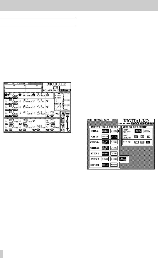
A typical screen showing POD use is shown below (the method of actually selecting screens is given below):
The controls on the screen are shown in rows, each row corresponding to the four PODs.
The heavy blinking box surrounding a row shows the currently-active row. Turning a POD knob will have the effect of changing the corresponding parameter in the active row (turning the left POD knob will adjust the left parameter in the active row, etc.).
In the example above, the right on-screen control in the active row is “grayed out”. This means that the corresponding POD has no function when this row is active.
Note that PODs which are enabled, but not in the currently active row, are shown as small dashed circles. PODs which are disabled, and not in the currently active row, are shown as small gray circles.
Where both switches of a POD are unused, they are not displayed on screen. When only one switch of a POD is used, the other is “grayed out”.
To change the active row, use the ROW CURSOR keys to the right of the PODs to move the heavy blinking box indicating the active row.
In addition to the POD knobs, the POD switches can also be used in a number of cases in this screen to set various parameters.
In this way, comparatively few physical controls can be made to adjust many parameters. Since these controls are centralized, this allows for very efficient working with the TM-D4000.
2.3.1 Selecting screens
Display screens are selected using the group of keys to the left of the display screen.
Sometimes a key will have two labels, one above and one below. The function described by the lower label is accessed by pressing the SHIFT key so that the SHIFT indicator lights, and then pressing the appropriate key.
The screen shown below is a DIGITAL I/O screen, as shown by the title in the top right corner of the screen. Accordingly, the (unshifted) key whose upper label is DIGITAL I/O should be pressed.
Note that this screen contains three “tabs” under the title. This is because there are more parameters which fall under the heading of “digital I/O” than can fit on one screen.
Currently, the I/O SETUP tab is at the top, and it is these parameters which are available for editing.
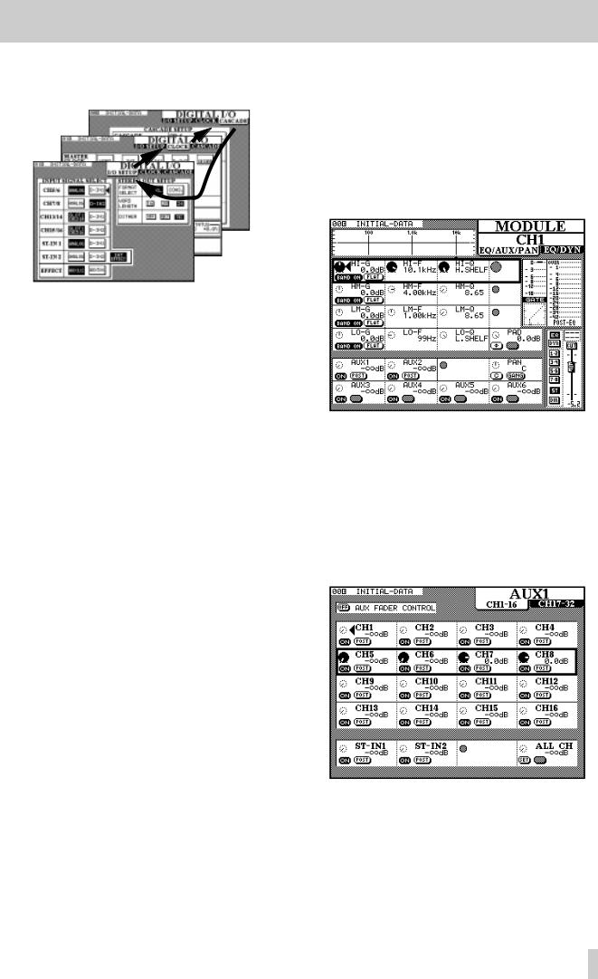
To change to the next tab, CLOCK, press the DIGITAL I/O key once more (with the SHIFT indicator lit).
Another press of the DIGITAL I/O key will bring the CASCADE tab to the front, and pressing it one
2–2
2 - Principles of operation—Using the PODs
more time will bring I/O SETUP to the front once more.
2.3.2 Navigation in screens
In the screens above, there are no POD-selectable parameters. In these cases, it is necessary to use another method of working.
This is provided by the cursor keys and the ENTER key beside the JOG/SHUTTLE dial.
Use the cursor keys to move the cursor (å) from field to field, and the ENTER key to select a value from one of a number of options.
2.3.3 Using the JOG dial
Sometimes there are numerical values to be set. These can be entered using the JOG dial (when the JOG/SHUTTLE indicator is off and the Dial Edit option is checked—see 3.3.7, “Dial edit”).
The JOG dial can also be used to change the values of a highlighted item which can also be edited by a POD (in the screen above, there are no such values, but the MODULE screen in 2.3, “Using the PODs” contains many such values). Note that the JOG dial can be used to control the values of a parameter that is not in the currently active POD row.
In some screens, the JOG dial may be used instead of the cursor keys to move the cursor around the screen. The instances where this can be performed are usually obvious and therefore will not be described in detail.
In certain special screens, the outer SHUTTLE wheel is used to change the function of a screen (for instance in library screens, it changes the function of the JOG dial from a device selector to a character selector.
The numeric keypad may also be used for the direct entry of numeric values in certain cases.
2.3.4 One channel or one parameter?
The TM-D4000 provides two options for the setting of module-based (as opposed to system-based) parameters.
If one module (or stereo linked pair of modules) is to have many parameters changed, at one time, the channel is selected (see 2.3.5, “Selecting channels” below) and the MODULE screen is used, as shown below:
In fact, the MODULE “screen” is two screens (EQ/AUX/PAN and EQ/DYN (dynamics processor)). Pressing the MODULE key will change between these two screens (see 2.3.1, “Selecting screens” for more information on multiple screens).
Sometimes, though, it makes more sense to view and adjust a single parameter on many modules simultaneously. For instance, here is the screen to adjust the levels for Aux send 1, accessed by pressing the
AUX 1 key:
Note that again, this “screen” is actually two screens, the first for the channels 1 through 16, and the second for channels 17 through 32. Repeated presses of the AUX 1 key will cycle between these two screens.
2–3
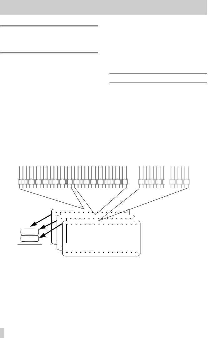
2 - Principles of operation—Fader layers
NOTE
Equalization is only available in the MODULE screen. There is no global equalization screen.
2.3.5 Selecting channels
In the case of the MODULE screens, which allow you to adjust the parameters of an individual channel (or pair of linked channels), it is necessary to select the channel whose parameters are to be edited. This is usually done with the individual channels’ SEL keys.
Pressing the SEL key of a channel (or either channel of a stereo linked pair of channels) will change the MODULE screen (when a MODULE screen is already displayed) to allow viewing and setting of that channel’s parameters.
If the MODULE screen is not already displayed, pressing and holding the SEL key of a channel for about two seconds will bring up the MODULE editing screen for that channel, if the appropriate option is set (see 3.3.5, “Select MODULE return”).
In addition, the SEL keys may also be used to jump around a screen quickly when a lot of channels are displayed simultaneously, rather than using the cursor keys to select a channel.
The channel faders may also be used to select channels for editing, together with other optional preferences concerned with the interface, as described in 3.3.4, “Fader select”.
2.4 Fader layers
The TM-D4000 can handle up to 32 mono inputs, together with two stereo inputs, and also has eight busses and six aux sends. However, only 19 faders are visible.
The way that faders are used is in “layers”—each layer consisting of 16 faders.
The three right faders always control the two stereo inputs and the stereo master buss, regardless of the settings of the other faders, except in the Aux send mode, where the mono and stereo input faders in the 1-16 and 17-32 layers act as Aux sends. In the MASTER layer, even if the Aux send option is selected, all faders retain their settings.
Channel faders 1–32 |
8 output busses 6 aux sends |
|
|
|
|
|
|
|
|
|
|
|
|
|
|
|
|
|
|
|
|
|
|
|
|
|
|
|
|
|
|
|
|
|
|
|
|
|
|
|
|
|
|
|
|
|
|
|
|
|
|
|
|
|
|
|
|
|
|
|
|
|
|
|
|
|
|
|
|
|
|
|
|
|
|
|
|
|
|
|
|
|
|
|
|
|
|
|
|
|
|
|
|
|
|
|
|
|
|
|
|
|
|
|
|
|
|
|
|
|
|
|
|
|
|
|
|
|
Layer 1 |
|
Layer 2 |
|
|
|
|
|
|
|
|
|
|
|
|
|
|
|
Layer 3 |
|||||||||||||||||||||||||||||||||||||||||||||||||||||||||||||
|
|
|
|
|
|
|
|
|
|
|
|
|
|
|
|
|
|
(CH 1-16) |
|
(CH 17-32) |
|
|
|
|
|
|
|
|
|
|
|
|
|
|
|
(MASTER) |
|||||||||||||||||||||||||||||||||||||||||||||||||||||||||||||
|
|
|
|
|
|
|
|
|
|
1 |
|
2 |
|
|
|
|
|
3 |
|
|
|
|
|
|
|
|
|
|
|
|
|
|
|
|
|
|
|
|
|
|
|
|
|
|
|
|
|
|
|
|
|
|
|
|
|
|
|
|
|
|
|
|
|
|
|
|
|
|
|
|
|
|
|
|
|
|
|
|
|
|
|
|
|||||||||||||||
|
|
|
|
|
|
|
|
|
|
|
|
|
|
|
|
|
|
|
|
|
|
|
|
|
|
|
|
|
|
|
|
|
|
|
|
|
|
|
|
|
|
|
|
|
|
|
|
|
|
|
|
|
|
|
|
|
|
|
|
|
|
|
|
|
|
|
|
|
|
|
|
|
|
|
|
|
|
||||||||||||||||||||
|
|
10 |
|
26 |
|
|
|
|
|
|
|
|
|
|
|
|
|
|
|
|
|
|
|
|
|
|
|
|
|
|
|
|
|
|
|
|
|
|
|
|
|
|
|
|
|
|
|
|
|
|
|
|
|
|
|
|
|
|
|
|
|
|
|
|
|
|
|
|
|
|
|
|
|
|
|
|
|
|
|
|
|
|
|
|
|
|
|||||||||||
|
|
|
|
|
|
|
|
|
|
|
|
|
|
|
|
|
|
|
|
|
|
|
|
|
|
|
|
|
|
|
|
|
|
|
|
|
|
|
|
|
|
|
|
|
|
|
|
|
|
|
|
|
|
|
|
|
|
|
|
|
|
|
|
|
|
|
|
|
|
|
|
|
|
|
|
|
|
|
|
|
|
|
|
|
|||||||||||||
|
|
|
|
|
|
|
|
|
|
|
|
|
|
|
|
|
|
|
|
|
|
|
|
|
|
|
|
|
|
|
|
|
|
|
|
|
|
|
|
|
|
|
|
|
|
|
|
|
|
|
|
|
|
|
|
|
|
|
|
|
|
|
|
|
|
|
|
|
|
|
|
|
|
|
|
|
|
|
|
|
|
|
|
|
|
|
|
||||||||||
|
|
|
|
|
|
|
|
|
|
|
|
|
|
|
|
|
|
|
|
|
|
|
|
|
|
|
|
|
|
|
|
|
|
|
|
|
|
|
|
|
|
|
|
|
|
|
|
|
|
|
|
|
|
|
|
|
|
|
|
|
|
|
|
|
|
|
|
|
|
|
|
|
|
|
|
|
|
|
|
|
|
|
|
|
|
|
|
||||||||||
|
|
|
|
|
|
|
|
|
|
|
|
|
|
|
|
|
|
|
|
|
|
|
|
|
|
|
|
|
|
|
|
|
|
|
|
|
|
|
|
|
|
|
|
|
|
|
|
|
|
|
|
|
|
|
|
|
|
|
|
|
|
|
|
|
|
|
|
|
|
|
|
|
|
|
|
|
|
|
|
|
|
|
|
|
|
|
|
|
|||||||||
|
|
|
|
|
|
|
|
|
|
|
|
|
|
|
|
|
|
|
|
|
|
|
|
|
|
|
|
|
|
|
|
|
|
|
|
|
|
|
|
|
|
|
|
|
|
|
|
|
|
|
|
|
|
|
|
|
|
|
|
|
|
|
|
|
|
|
|
|
|
|
|
|
|
|
|
||||||||||||||||||||||
|
|
|
AUX 2 |
|
|
|
|
|
|
|
|
|
|
|
|
|
|
|
|
|
|
|
|
|
|
|
|
|
|
|
|
|
|
|
|
|
|
|
|
|
|
|
|
|
|
|
|
|
|
|
|
|
|
|
|
|
|
|
|
|
|
|
|
|
|
|
|
|
|
|
|
|
|
|
|
|
|
|
|
|
|
|
|
|
|
|
|
||||||||||
|
|
|
|
|
|
|
|
|
|
|
|
|
|
|
|
|
|
|
|
|
|
|
|
|
|
|
|
|
|
|
|
|
|
|
|
|
|
|
|
|
|
|
|
|
|
|
|
|
|
|
|
|
|
|
|
|
|
|
|
|
|
|
|
|
|
|
|
|
|
|
|
|
|
|
|
|
|
|
|
||||||||||||||||||
|
|
(fader strip |
|
|
|
|
|
|
|
|
|
|
|
|
|
|
|
|
|
|
|
|
|
|
|
|
|
|
|
|
|
|
|
|
|
|
|
|
|
|
|
|
|
|
|
|
|
|
|
|
|
|
|
|
|
|
|
|
|
|
|
|
|
|
|
|
|
|
|
|
|
|
|
|
|||||||||||||||||||||||
|
|
|
|
|
|
|
|
|
|
|
|
|
|
|
|
|
|
|
|
|
|
|
|
|
|
|
|
|
|
|
|
|
|
|
|
|
|
|
|
|
|
|
|
|
|
|
|
|
|
|
|
|
|
|
|
|
|
|
|
|
|
|
|
|
|
|
|
|
|
|
|
|
|||||||||||||||||||||||||
|
|
|
|
|
|
|
|
|
|
|
|
|
|
|
|
|
|
|
|
|
|
|
|
|
|
|
|
|
|
|
|
|
|
|
|
|
|
|
|
|
|
|
|
|
|
|
|
|
|
|
|
|
|
|
|
|
|
|
|
|
|
|
|
|
|
|
|
|
|
|
|
||||||||||||||||||||||||||
|
|
|
|
|
|
|
|
|
|
|
|
|
|
|
|
|
|
|
|
|
|
|
|
|
|
|
|
|
|
|
|
|
|
|
|
|
|
|
|
|
|
|
|
|
|
|
|
|
|
|
|
|
|
|
|
||||||||||||||||||||||||||||||||||||||||||
|
|
label) |
|
|
|
|
|
|
|
|
|
|
|
|
|
|
|
|
|
|
|
|
|
|
|
|
|
|
|
|
|
|
|
|
|
|
|
|
|
|
|
|
|
|
|
|
|
|
|
|
|
|
|
|
|
|
|
|
|
|
|
|
|
|
|
|
|
|
|
|
|
|
|
|
|
|
|
|
|
|
|
|
|
|
|
|
|
|
|
|
|
|
|||||
|
|
|
|
|
|
|
|
|
|
|
|
|
|
|
|
|
|
|
|
|
|
|
|
|
|
|
|
|
|
|
|
|
|
|
|
|
|
|
|
|
|
|
|
|
|
|
|
|
|
|
|
|
|
|
|
|
|
|
|
|
|
|
|
|
|
|
|
|
|
|
|
|
|
|
|
|
|
|
|
|
|
|
|
|
|
|
|
|
|
|
|
||||||
The three layers are selected using the LAYER |
|
|
|
|
|
|
|
|
|
|
|
|
|
|
|
|
|
|
|
|
|
|
|
|
|
|
|
|
|
|
|
|
|
|
|
|
|
|
|
|
|
|
|
|
|
|
|
|
|
|
|
|
|
||||||||||||||||||||||||||||||||||||||||||||
|
|
|
|
|
|
|
|
|
|
|
|
|
|
|
LAYER |
|
|
|
|
|
|
|
|
|
|
|
|
|
|
|
|
|
|
Meaning |
|||||||||||||||||||||||||||||||||||||||||||||||||||||||||||||||
STATUS keys (the appropriate indicator will light). |
|
|
|
|
|
|
|
|
|
|
|
|
|
|
|
|
|
|
|
|
|
|
|
||||||||||||||||||||||||||||||||||||||||||||||||||||||||||||||||||||||||||
|
|
|
|
|
STATUS |
|
|
|
|
|
|
|
|
|
|
|
|
|
|
|
|
|
|
||||||||||||||||||||||||||||||||||||||||||||||||||||||||||||||||||||||||||
|
|
|
|
|
|
|
|
|
|
|
|
|
|
|
|
|
|
|
|
|
|
|
|
|
|
|
|
|
|
|
|
|
|
|
|
|
|||||||||||||||||||||||||||||||||||||||||||||||||||||||||||||
These three keys are interlocking, i.e. only one can |
|
|
|
|
|
|
|
|
|
|
|
|
|
|
|
|
|
|
|
|
|
|
|
|
|
|
|
|
|
|
|
|
|
|
|
|
|
|
|
|
|
|
|
||||||||||||||||||||||||||||||||||||||||||||||||||||||
|
|
CH 17–32 |
|
|
Faders 1–8 control the channel inputs from slot |
||||||||||||||||||||||||||||||||||||||||||||||||||||||||||||||||||||||||||||||||||||||||||||
be active at a time, and have the following meanings: |
|
|
|
|
|||||||||||||||||||||||||||||||||||||||||||||||||||||||||||||||||||||||||||||||||||||||||||||
|
|
|
|
|
|
|
|
|
|
|
|
|
2, and faders 9–16 control the channel inputs |
||||||||||||||||||||||||||||||||||||||||||||||||||||||||||||||||||||||||||||||||||||
|
|
|
|
|
|
|
|
|
|
|
|
|
|
|
|
|
|
|
|
|
|
|
|
|
|
|
|
|
|
|
|
|
|
|
|
|
|
|
|
|
|
|
|
|
|
|
|
|
|
|
|
|
|
|
|
|
|
|
|
|
|
|
|
|
|
|
|
||||||||||||||||||||||||||||||
|
|
|
|
|
|
|
|
|
|
|
|
|
|
|
|
|
|
|
|
|
|
|
|
|
|
|
|
|
|
|
|
|
|
|
|
|
|
|
|
|
|
|
|
|
|
|
|
|
|
|
|
|
|
|
|
|
|
|
|
|
|
|
|
|
|
|
|
from slot 3 |
|||||||||||||||||||||||||||||
LAYER |
|
|
|
|
|
|
|
|
|
|
|
|
|
|
|
|
|
|
|
|
|
Meaning |
|
|
|
|
|
|
|
|
|
|
|
|
|
|
|
|
|
|
|
|
|
|
|
||||||||||||||||||||||||||||||||||||||||||||||||||||
|
|
|
|
|
|
|
|
|
|
|
|
|
|
|
|
|
|
|
|
|
|
|
|
|
|
|
|
|
|
|
|
|
|
|
|
|
|
|
|
|
|
|
|
|
|
|
|
|
|
|
|
|
|
|
|
|
|
|
|
|
|
|
|
|
|
|
|
|
|
|
|
|
|
||||||||||||||||||||||||
STATUS |
|
|
|
|
|
|
|
|
|
|
|
|
|
|
|
|
|
|
|
|
|
|
|
|
|
|
|
|
|
|
|
|
|
MASTER |
|
|
Faders 1–8 control the levels of the signals fed |
||||||||||||||||||||||||||||||||||||||||||||||||||||||||||||
|
|
|
|
|
|
|
|
|
|
|
|
|
|
|
|
|
|
|
|
|
|
|
|
|
|
|
|
|
|
|
|
|
|
|
|
|
|
|
|
|
|
|
|
|
|
|
|
|
|
|
|
|
|
|
|
|
|||||||||||||||||||||||||||||||||||||||||
|
|
|
|
|
|
|
|
|
|
|
|
|
|
|
|
|
|
|
|
|
|
|
|
|
|
|
|
|
|
|
|
|
|
|
|
|
|
|
|
|
|
|
|
|
|
|
|
|
|
|
|
|
|
|
|
|
|
|
|
|
|
|
|
|
|
|
|
to the eight output busses. Faders 9–14 control |
|||||||||||||||||||||||||||||
CH 1-16 |
|
|
|
Faders 1–8 control the inputs from the integral |
|
|
|
|
|
|
|
|
|
|
|
|
|
||||||||||||||||||||||||||||||||||||||||||||||||||||||||||||||||||||||||||||||||
|
|
|
|
|
|
|
|
|
|
|
|
|
|
|
|
the levels of the six aux sends. Faders 15 and |
|||||||||||||||||||||||||||||||||||||||||||||||||||||||||||||||||||||||||||||||||
analog inputs, and faders 9–16 control the |
|
16 are unused in this fader layer. |
channel inputs from slot 1 |
|
|
|
|
|
|
|
|
|
|
|
2–4

2 - Principles of operation—Fader layers
Every time the fader layer is changed, the faders will move to the positions corresponding to the new layer.
NOTE
In addition to the faders, the REC, SEL, SOLO and CUT keys, as well as the channel automation indicators above each fader all
change function to control the appropriate input channel, buss or aux send. However, in this manual we sometimes use the term “fader” as a shorthand expression for all these items.
Note that there are some modes where the fader controls do not act as channel, Aux or buss faders. These are principally the Aux Fader Control mode (see 4, “Module operations”) and MIDI Fader (10.5, “MIDI Faders”) modes (some Machine Control settings may also use the faders). If the current fader layer is not controlling module (or Aux or buss) levels, the cur- rently-selected indicator will ash.
NOTE
In the Aux Fader Control mode, the MASTER layer functions do not change. Accordingly, the STEREO IN faders act as channel faders in the MASTER layer when the Aux Fader Con-
trol mode is selected, not as Aux sends for the stereo channels.
2.4.1 Turning fader motors on and off
The fader motorization can be turned on and off as n described in 3.3.8, “Automation fader inhibit”..
This setting only takes effect in automation replay (Read) mode. In all other cases such as fader layer changes, snapshot recall, etc., the faders are always motorized.
2.4.2 Physical and logical faders
When automation operations are taking place, we can speak of “physical” and “logical” faders.
The “physical” faders, as the name implies, are the actual controls (the fader knobs). The “logical” faders, on the other hand are not visible, and are the positions that the physical faders would occupy for the current level.
NOTE
The positions of the physical and logical faders will always be the same when fader motorization is turned on.
2–5
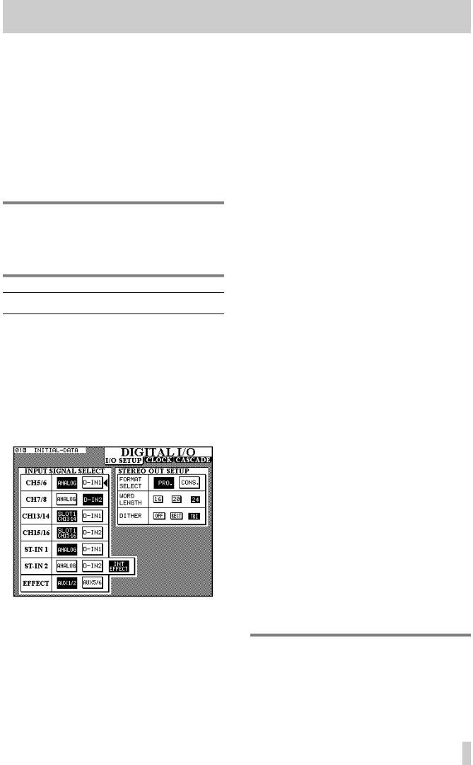
This section describes the operations that should be carried out to affect the operation of the TM-D4000 as a whole.
These include:
•Digital I/O setup
•Word clock setup
•System options
It is important to understand the basic principles explained here. If you do not, it will be more difficult to achieve satisfactory results with your TM-D4000.
NOTE
The Cascade setup (accessed through the DIGITAL I/O key) is described in 11, “Cascade”, the Solo setup in 5, “Monitoring”, and the Surround setup in 6, “Surround modes”.
3.1I/O setup
1With the SHIFT indicator off, press the DIGITAL I/O key [5] until the screen below appears.
This screen allows the selection and assignment of the digital inputs to channels. Note that the same digital input may appear as an input option for more than one pair of channels. If a digital input is selected as the source of more than one pair of channels, it will appear at all these channels simultaneously.
3 - System setup
The options available are:
|
|
Input channels |
Available sources |
|
||
|
|
|
|
|||
|
|
|
|
|
|
|
|
|
5 & 6 |
Analog (integral |
D-IN1 (XLR- |
|
— |
|
|
|
analog chan- |
type) |
|
|
|
|
|
nels 5 and 6) |
|
|
|
|
|
|
|
|
|
|
|
|
7 & 8 |
Analog (integral |
D-IN2 (RCA) |
|
— |
|
|
|
analog chan- |
|
|
|
|
|
|
nels 7 and 8) |
|
|
|
|
|
|
|
|
|
|
|
|
13 & 14 |
Slot 1 CH13-14 |
D-IN1 (XLR- |
|
— |
|
|
|
(channels 7 and |
type9 |
|
|
|
|
|
8 of the card in |
|
|
|
|
|
|
slot 1) |
|
|
|
|
|
|
|
|
|
|
|
|
|
|
|
|
|
|
|
15 & 16 |
Slot 1 CH15–16) |
D-IN2 (RCA) |
|
— |
|
|
|
channels 7 and |
|
|
|
|
|
|
8 of the card in |
|
|
|
|
|
|
slot 1) |
|
|
|
|
|
|
|
|
|
|
|
|
|
|
|
|
|
|
|
ST-IN 1 |
ANALOG (inte- |
D-IN1 (XLR- |
|
— |
|
|
|
gral stereo |
type) |
|
|
|
|
|
inputs) |
|
|
|
|
|
|
|
|
|
|
|
|
ST-IN 2 |
ANALOG (inte- |
D-IN2 (RCA) |
|
INT |
|
|
|
gral stereo ana- |
|
|
EFFECT |
|
|
|
|
|
||
|
|
|
log inputs |
|
|
(internal |
|
|
|
|
|
|
effect pro- |
|
|
|
|
|
|
cessor) |
|
|
|
|
|
|
|
|
|
EFFECTa |
AUX1/2 (Aux |
AUX5/6 |
|
— |
|
|
|
busses 1 and 2) |
(Aux bus- |
|
|
|
|
|
|
ses 5 and 6) |
|
|
|
|
|
|
|
|
|
|
|
|
|
|
|
|
a.The source of the internal effect processor input
3.1.1 STEREO OUT settings
In addition to these input sources, changes to parameters affecting the digital output of the STEREO OUT can be made.
Firstly, the STEREO OUT can be selected as being in either professional (PRO.) or consumer (CONS.) format.
Changing the setting made here will also affect the format of the output from any IF-AE4000 interface cards fitted in the expansion slots.
NOTE
The Consumer format, when output from the unbalanced RCA STEREO OUT jack, corresponds to the IEC61958 (SPDIF) format.
3–1
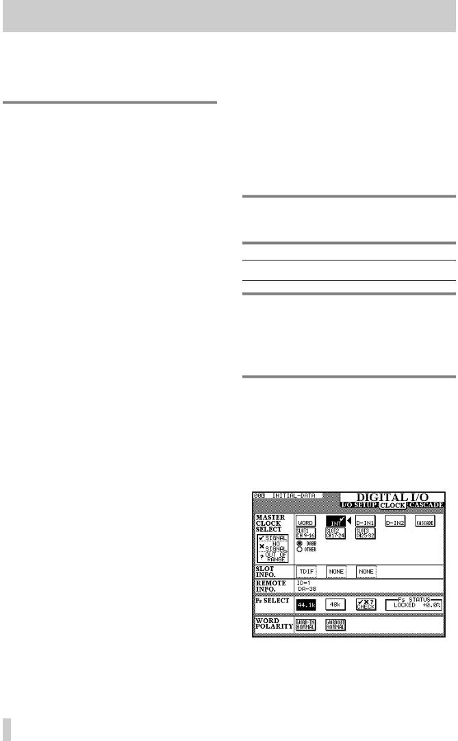
3 - System setup—CLOCK setup
If the Professional format is selected, the resulting data output from the RCA STEREO OUT jack will probably be unusable by most domestic equipment.
3.1.2 Consumer options
If the chosen output is Consumer, hold down the SHIFT key and press the right switch of POD 4 to change the SCMS (copy-protect) settings between FREE (SCMS disabled), ONCE (standard SCMS one-generation) and NO COPY ((copy-prohibit). An appropriate message will appear on screen, and these settings are stored in memory.
In addition, the category of consumer audio can be set using the SHIFT key along with the left switch of POD 4 to cycle through the following values:
General |
General |
|
|
CD |
CD |
|
|
LD |
Laser (usually disc) |
|
|
MD |
MD |
|
|
CODEC |
PCM Codec |
|
|
MIXER |
Mixera |
SRC |
SRC (Sample Rate Converter) |
|
|
SAMPLER |
Sampler |
|
|
DAT |
DAT |
|
|
DVTR |
DVTR |
|
|
DCC |
DCC |
|
|
TV-J |
Japanese broadcast digital |
|
|
TV-EUR |
European broadcast digital |
|
|
TV-USA |
American broadcast digital |
|
|
TV |
Broadcast digital |
|
|
Synth |
Synthesizer |
|
|
Microphone |
Microphone |
|
|
Pro A/D |
Copy-free A/D converter |
|
|
A/D |
A/D converter |
|
|
RAM |
Solid state reproducer |
|
|
a. TM-D4000 default setting
This allows the TM-D4000 to pose as an alternative audio source, for instance if an MD deck can only accept signals from a CD or another MD deck, or in a broadcast situation, a certain category may be necessary for use with other equipment.
If an attempt is made to set the category with the Professional format setting, an error message, “No Category for AES/EBU” will appear on screen.
3.1.3 Word length and dithering
The word length can be selected as being either 16, 20 or 24 bits in length.
If the selected word length is less than 24 bits, you may choose to dither the resulting output. Dithering helps to reduce quantization noise, but results in a slightly lower signal-to-noise ratio. Choose either OFF, rectangular (RECT) or triangular (TRI) dithering. The shape names refer to the probability distribution of the noise which is used in the dithering process.
Typically, triangular dithering gives better quantization noise reduction than rectangular, but the signal- to-noise ratio is not as good.
NOTE
The word length from the output busses is always set to 24 bits.
3.2 CLOCK setup
WARNING
There should be one, and only one, word clock source in a digital audio setup. Multiple word clocks in a setup may result in noise which can damage monitoring equipment (speakers and amplifiers).
The word clock source is selected in the following way:
1With the SHIFT indicator unlit, press the DIGITAL I/O key until the screen below is shown (note that the exact screen may differ from that shown here, depending on the number and the type of the interface cards fitted in the expansion slots):
2Move the cursor to the box which contains the description of the desired clock source.
3–2
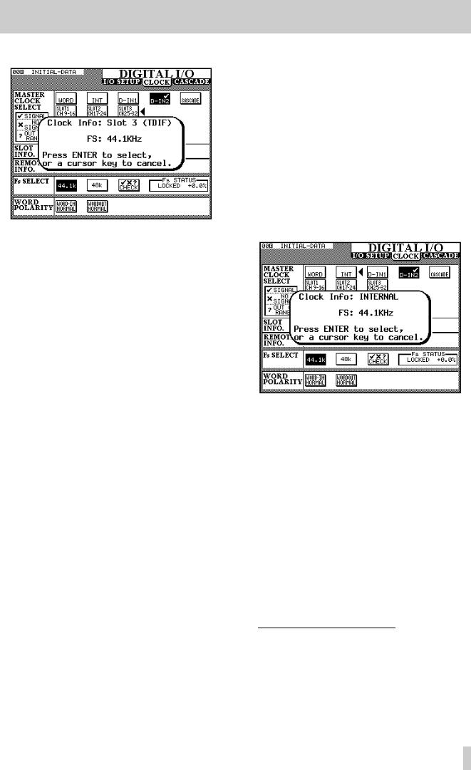
3 - System setup—CLOCK setup
3 Select the clock source by pressing ENTER.
The popup panel provides information about the potential clock source. Press ENTER to select this source, or any one of the cursor keys to dismiss the popup panel, and select another source.
In the case of an IF-AE4000 (AES/EBU interface card), there are four different sources (the four AES/EBU inputs) which may be selected as the word clock source for the TM-D4000.
If the TM-D4000 has been cascaded from another unit, the clock source is set as CASCADE and cannot be changed. The
“head” of the cascade chain can select the clock from any source.
In the case of an IF-TD4000 (TDIF-1 interface card), the device attached to the card source is shown as either a DA88 ( DA-88 DTRS recorder) or OTHER (another type of recorder connected through the TDIF-1 interface). If the indicator shows DA88, then I/O data is truncated to 16 bits, otherwise I/O is carried out at 24 bits.
In the case of an IF-LP4000 (ADAT “lightpipe” interface card), there are three options: INT, SYNC or DIGI. If more than one IF-LP4000 is fitted, changing the setting for one card will change the settings for all the rest. The INT setting allows the
ADAT to act as the clock master (this is not a recommended setting). If SYNC is selected, the ADAT receives its clock through the SYNC cable, and if DIGI is selected, the optical connection is used as the clock source to the ADAT. We strongly suggest that SYNC is used, rather than DIGI, if the
ADAT is to be a word clock slave, especially if more than one ADAT is connected. See also 9.4.4, “ADAT devices”.
If more than one IF-LP4000 card is fitted, there are three choices for each card, regardless of the actual connection of the ADAT units to the TM-D4000. The last on-screen button pressed (on any of the IF-LP4000 options) then determines the status of the first ADAT in the chain.1
4If the clock source has been selected as INT, the clock rate (sampling frequency) can be selected. In all other cases, the sampling frequency is fixed and cannot be changed.
3.2.1 Selecting clock frequencies
Word clock sources, except for WORD and ADAT sources, include information regarding their sampling frequencies. If either WORD or ADAT is selected as a clock source, the procedure below should be followed:
1Decide what sampling frequency the project will use.
2Select INT as the clock source (this is a temporary measure), and select the frequency.
3Select the final clock source (WORD or ADAT). The TM-D4000 sampling frequency will now match the incoming word clock.
1.Note that the other ADAT units, “daisychained” to the first ADAT unit in the chain with SYNC connections, will be automatically set to take their clock from the SYNC connector, and their IDs will also be set automatically, regardless of setting made here.
3–3
3 - System setup—Option setup
3.2.2 Clock check
The status of all possible clock sources currently connected to the TM-D4000 can be checked by moving the cursor to the CHECK box and pressing ENTER. The console will mute, and a list of available clock sources will be shown.
Press ENTER to continue operations.
3.2.3 Clock settings (other)
The Fs STATUS box shows the status of the currently selected clock source.
The WORD POLARITY settings allow either incoming or outgoing word clock information to be inverted (REVERSE) relative to normal. This is because some units either transmit or expect to receive such signals in this inverted format.
3.2.4 Clock tolerance
When setting the clock, the sampling frequency received can be ±6% of the stated nominal value. When in use, the frequency can be ±7% of the stated value. This allows a digital device which has a varispeed feature to be used as the word clock source for the TM-D4000.
If the selected clock source goes out of range, the TM-D4000 will mute, the currently-selected clock
indicator will flash, and a message will appear on the display:
The TM-D4000 will report the out-of-range clock frequency at a range of ±9.9% relative to the stated frequency, but will mute at 7.0% or over.
Press the ENTER key to dismiss the popup message, change to the CLOCK screen, and correct the error condition (by selecting another clock source, or by re-selecting the clock if it has come back into range).
3.3 Option setup
In unshifted mode, this key is used to show the OPTION screens. There are three of these screens: SETUP, SOLO and SURROUND, and they are accessed by repeated presses of the
OPTION key.
The solo operations are explained in 4, “Module operations”, and the surround operations in 6, “Surround modes”.
The SETUP screen provides the following options (as well as displaying the current battery voltage, used to power the memory holding library entries, etc.) as shown and described below:
These settings are generally made using the cursor keys to move the cursor to the parameter to be
3–4

changed, and the ENTER key is then used to make the setting.
3.3.1 Location display mode
When using the TM-D4000’s location facilities to control an external device, the value of the location points (LOCATE DISPLAY MODE) can be displayed either on the main time counter (7- Seg LED) or as a “pop-up” panel on the main display screen (LCD Screen Pop-up). These options are mutually exclusive, i.e. you can only choose one.
3.3.2 Timecode source
The timecode displayed on the time counter can be taken from the timecode source used for automation timing (Automation Sync Source), directly from a DTRS recorder through the REMOTE IN terminal (MDR ABS Absolute Time) or received at the MIDI IN terminal as MIDI timecode (MIDI IN MTC [MIDI Time Code]). This timecode source is also used when controlling external devices (see 9, “Machine Control”). Again, only one of these options can be selected.
3.3.3 Preferences
The PREFERENCESare as follows: Fader Auto MODULE Select, Select MODULE Return, Select Link and Dial Edit, Automation Fader Motors Inhibit and Balance Level CENTER 0dB. Any number of these preferences can be selected, as indicated by a check mark in the checkboxes ( ).
3.3.4 Fader select
When checked, and the MODULE screen is currently displayed this option allows a module to be selected whenever its fader is moved, in addition to the usual method of pressing the SEL key.
3.3.5 Select MODULE return
When checked, this option allows the MODULE screen of the appropriate module to appear (even if a MODULE screen is not currently displayed) if the SEL key of the module is pressed and held for about two seconds.
3.3.6 Select link
When checked, this option allows the stereo linking of two adjacent modules (provided the left module is odd-numbered) by pressing and holding the SEL key
3 - System setup—Option setup
of one module and pressing the SEL key of the other. See 4.2.2, “Using the SEL keys to link channels”.
3.3.7 Dial edit
When checked, this option allows the JOG dial to be used as a data entry dial for the on-screen control pointed to by the triangular cursor, which is usually controlled by a POD knob. In effect, this provides another POD. In addition to this option being checked, the JOG/SHUTTLE indicator must be off when using the JOG dial in this way, to prevent the JOG dial being used as a transport control.
3.3.8 Automation fader inhibit
The Automation Fader Motors Inhibit setting allows the motorization of the faders to be turned off or on for automation replay (Read) purposes. See 2.4.1, “Turning fader motors on and off”.
3.3.9 Balance level
When two channels are linked together as a stereo pair, the pan controls change to a balance control, as mentioned earlier. In the center position, the level may either be set to 0dB (checked) or a 3 dB cut (unchecked).
3.3.10Oscillator
The integral line-up oscillator can be turned using the left switch of POD 2 and the frequency adjusted with the POD 1 control. It can be assigned to either the left or right main output buss, (L Buss,
R buss), Both of these, or neither using the switches of POD 1. The left busses are the odd-num- bered output busses (1, 3, 5, 7) and the left channel of the stereo output buss. The right busses are the evennumbered output busses (2, 4, 6, 8) and the right channel of the stereo output buss.
The POD 1 rotary control is used to change the level of the oscillator, relative to full-scale.
3.3.11Meter ballistics
The release rate (“fall time”) and peak hold time of the meters and can be adjusted using the knobs of PODs 3 and 4.
The release rate can be set to Fast, Normal or Slow.
The hold time can be set to 0sec, 1sec, 2sec, 4sec, 8sec or ˚. The final (infinity) setting will hold the peak value until a new setting is made (or the TM-D4000 is turned off!).
3–5
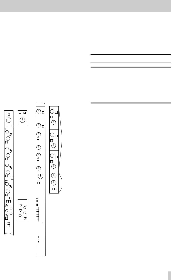
4 - Module operations
The input modules of the TM-D4000 are of two types: mono input and stereo inputs. There is no difference between a “tape return” channel, an “effects return” and an input channel—all modules are equipped with the same features.
The digital parts of the mono input modules are identical, regardless of what interface card is fitted. The only difference between mono modules is that modules 1 through 8 use the integral mic amplifiers and A/D convertors. These analog features (MIC/LINE switch, phantom powering, analog pad and gain, etc.) work in an identical way to similar features on a conventional analog console. If you are unsure about the operation of these items, consult 13, “Rear panel & connections”.
If the digital functions of the modules were “converted” to analog controls, a module would look similar to the following:
|
|
|
|
|
|
|
|
|
|
|
|
AUX 1 |
AUX 1-2 |
|
||||
PHASE (Φ) |
|
L R |
|
|
|
PRE/POST |
PRE/POST |
|
||||||||||
PHASE (Φ) |
|
|
|
|
|
|
|
|
|
|||||||||
|
|
|
|
|
|
|
|
|
|
LINK |
|
|
|
UNLINK |
|
|||
|
PAD |
|
PAD |
|
|
AUX 2 |
|
|
||||||||||
|
|
|
|
|
|
|
|
|
PAN |
|
||||||||
HI |
ON |
Stereo |
|
|
|
|
|
|
|
|
||||||||
|
|
|
|
|
|
|
|
|
||||||||||
|
|
SHELF |
|
|
|
PRE/POST |
|
|
||||||||||
|
|
inputs & |
|
|
|
|
|
|||||||||||
|
|
|
F |
stereo |
|
|
AUX 3 |
AUX 3-4 |
|
|||||||||
|
Q |
|
|
|
|
linked |
|
|
|
|
|
|
|
|
|
|||
|
|
|
|
|
pairs |
|
|
|
|
|
|
|
|
Stereo |
||||
|
|
|
|
|
|
|
|
|
|
|
|
|
|
|||||
|
|
|
|
|
|
|
|
|
|
|
|
|
|
|
|
|
|
|
|
|
|
G |
|
|
|
|
|
|
|
|
|
|
|
PRE/POST |
linked Aux |
||
|
|
LPF |
|
|
|
|
LINK |
|
|
|
|
sends |
||||||
|
|
|
|
|
|
|
|
|
|
PAN |
UNLINK |
|
||||||
|
|
|
|
|
|
|
|
|
|
|
|
AUX 4 |
|
|
||||
HI-MID ON |
|
|
|
|
|
|
|
|
|
|
|
|
|
|
|
|||
|
|
|
F |
|
|
|
|
|
|
|
|
|
|
|
|
|
PAN |
|
|
|
|
|
|
|
|
|
|
|
|
|
|
|
|
|
|
|
|
|
Q |
|
|
|
|
|
|
|
|
|
|
AUX 5 |
AUX 3-4 |
|
||||
|
|
|
|
|
|
|
|
|
|
|
|
|
||||||
|
|
|
G |
|
|
|
|
|
|
|
|
|
|
|
|
|
||
|
|
NOTCH |
|
|
|
|
|
|
|
|
|
|
|
PRE/POST |
|
|||
|
|
|
|
|
|
|
|
|
|
LINK |
|
|
|
|
|
|||
LO-MID ON |
|
|
|
|
|
|
|
|
|
|
|
|
|
UNLINK |
|
|||
|
|
|
F |
|
|
|
|
|
|
|
|
AUX 6 |
|
|
||||
|
|
|
|
|
|
|
|
|
|
|
|
|
|
|||||
|
Q |
|
|
|
|
|
|
|
|
|
|
|
|
|
|
|
|
|
|
|
|
|
|
|
|
|
|
|
|
|
|
|
|
|
|
PAN |
|
|
|
|
G |
|
|
|
|
|
|
|
|
|
|
|
|
|
||
|
|
|
|
|
|
|
|
|
|
|
|
|
|
|
|
|||
|
|
NOTCH |
|
|
|
|
|
|
|
|
|
|
|
|
|
|||
|
|
|
|
|
|
|
|
|
|
|
|
|
|
|
|
|
|
|
LO |
ON |
|
|
|
|
|
|
|
PAN |
IMAGE |
Stereo |
|||||||
|
|
SHELF |
|
|
|
|
|
|
|
|||||||||
|
|
|
|
|
|
|
|
|
|
|||||||||
|
|
|
|
|
|
|
|
|
|
|
|
|
|
inputs & |
||||
|
|
|
F |
|
|
|
|
|
|
|
|
|
|
|
|
|||
|
|
|
|
|
|
|
GANG* |
|
stereo linked |
|||||||||
|
|
|
|
|
|
|
|
|
|
|
||||||||
|
Q |
|
|
|
|
|
|
|
|
|
|
|
|
|
|
|
BALANCE |
pairs |
|
|
|
G |
|
|
|
|
|
|
|
|
|
|
|
L R |
|
||
|
|
|
|
|
|
|
|
|
|
|
|
|
|
|
|
|
MONO |
|
|
|
HPF |
|
|
|
|
|
C U T |
|
SOLO |
|
|
||||||
|
|
|
|
|
|
|
|
|
|
|
|
|
|
|||||
EQ |
|
|
|
|
|
|
|
|
|
|
|
|
|
|||||
|
|
|
|
|
|
OFF |
|
|
|
|
|
|||||||
|
|
|
|
|
|
|
|
|
|
|
|
1 |
CUT |
|
|
|||
|
|
|
|
|
|
|
|
|
|
|
|
2 |
|
|
||||
|
|
|
|
|
|
|
|
|
|
|
|
|
43 GROUP |
|
|
|||
|
|
|
|
|
|
C O M P / G AT E |
|
|
5 |
|
|
|
|
|
||||
C O M P / G AT E |
|
|
|
|
|
|||||||||||||
|
|
6 |
|
|
|
|
|
|||||||||||
|
|
|
|
|
|
|
THRSH |
|
|
7 |
|
|
|
|
|
|||
|
|
ATT |
|
|
|
8 |
|
|
|
|
|
|||||||
|
|
|
|
|
|
|
|
|
|
|
||||||||
REL |
RANGE |
1-2 |
|
|
|
|||||||||||||
|
|
THRSH |
|
|
HYST |
3-4 |
|
|
|
|||||||||
RATIO |
ATT |
5-6 |
|
|
|
|||||||||||||
|
|
|
|
7-8 |
|
|
|
|||||||||||
|
|
OUT GAIN |
|
|
HOLD |
|
|
|
||||||||||
|
|
AUTO |
DECAY |
|
|
|
L-R ST |
|
|
|||||||||
|
|
|
|
|
|
|
|
|
|
|
||||||||
|
|
|
|
|
|
|
|
|
|
|
|
|
DIRECT |
|
|
|||
DYNAMICS |
Gate |
|
|
|
OUT |
|
|
|||||||||||
|
|
|
|
|
|
|
|
|
||||||||||
|
|
|
ON/OFF |
selected |
|
|
|
|
|
|
|
|
|
|||||
|
|
|
|
|
|
|
|
|
|
|
|
|
|
|
||||
|
|
|
|
LINK |
as |
|
|
|
|
|
|
|
|
|
||||
|
TRIGGER |
dynamic |
|
|
|
|
|
|
|
|
|
|||||||
|
|
|
|
|
|
|
|
|
||||||||||
|
|
|
|
|
|
|
|
|
||||||||||
|
|
|
|
|
|
processor |
|
|
|
|
|
|
|
|
|
|||
|
|
|
|
|
|
|
|
|
|
|
|
|
|
|
||||
|
|
|
|
|
|
|
|
|
|
|
|
|
|
|
||||
L |
R BOTH |
|
|
|
|
|
|
|
|
|
||||||||
|
|
|
|
|
|
|
|
|
|
|
|
|
||||||
|
|
|
|
|
|
|
|
|
|
|
|
|
|
|
|
|
|
|
|
|
|
|
|
|
|
|
|
|
|
|
|
|
|
|
|
|
|
|
|
|
|
|
|
|
|
|
|
|
FADER |
|
|
|
||||
|
|
|
|
|
|
|
|
|
|
|
GROUP |
|
|
|
||||
|
|
|
|
|
|
|
|
|
|
|
|
|
OFF |
|
|
|
||
|
|
|
|
|
|
|
|
|
|
|
|
|
|
1 |
|
|
|
|
|
|
|
|
|
|
|
|
|
|
|
|
|
|
2 |
|
|
|
|
|
|
|
|
|
|
|
|
|
|
|
|
|
|
3 |
|
|
|
|
|
|
|
|
|
|
|
|
|
|
|
|
|
|
4 |
|
|
|
|
|
|
|
|
|
|
|
|
|
|
|
|
|
|
5 |
|
|
|
|
|
|
|
|
|
|
|
|
|
|
|
|
|
|
6 |
|
|
|
|
|
|
|
|
|
|
|
|
|
|
|
|
|
|
7 |
|
|
|
|
|
|
|
|
|
|
|
|
|
|
|
|
|
|
8 |
|
|
|
|
|
|
|
|
|
|
|
|
|
|
|
|
|
|
|
|
|
|
|
*the GANG control is only available on odd-numbered modules
Dashed lines indicate options (e.g. the dynamics processor selected for each module can be a compressor/ limiter or a gate, but not both). Aux sends can be optionally linked, providing a PAN control. When channels are linked together in a stereo pair (see 4.2, “Stereo linking”), the PAN controls are replaced by an IMAGE control and a BALANCE control.
4.1 Module features and control
NOTE
This section contains the instructions for the everyday module operations, as described below. You should at least make yourself familiar with the contents of this section, so that you know which parts to use for reference if you need information.
Very briefly, the typical signal path is:
•phase (4.8, “Pad and phase(Φ)”
•digital trim (4.8, “Pad and phase(Φ)”)
•4-band EQ (4.3, “Equalization”)
•dynamics processor (comp/limiter or gate) (4.6, “Dynamics processor settings”)
•fader (self-explanatory—for details of fader grouping, see 4.9, “Fader and cut groups”)
•Aux sends (4.5, “Aux sends”
•cut and solo (cut groups are described in 4.9, “Fader and cut groups”, solo modes are described in 5, “Monitoring”)
•panpot (4.7, “Pan and balance”)
•channel-to-buss assignment (4.4, “Channel-to-buss assignments”)
4.1.1 Stereo out module
This module includes 4-band EQ facilities and a dynamics processor (identical to those provided on the other modules).
4.1.2 Control of module parameters
In many instances, there may be more than one way of controlling module parameters: e.g. from the MODULE screen, allowing the control of many parameters for a single module (or linked pair) and from a dedicated “global” screen, allowing the adjustment of a single parameter for many modules.
These are described in 2.3.4, “One channel or one parameter?”. In this section, the appropriate way(s) of working are described for each parameter.
4–1
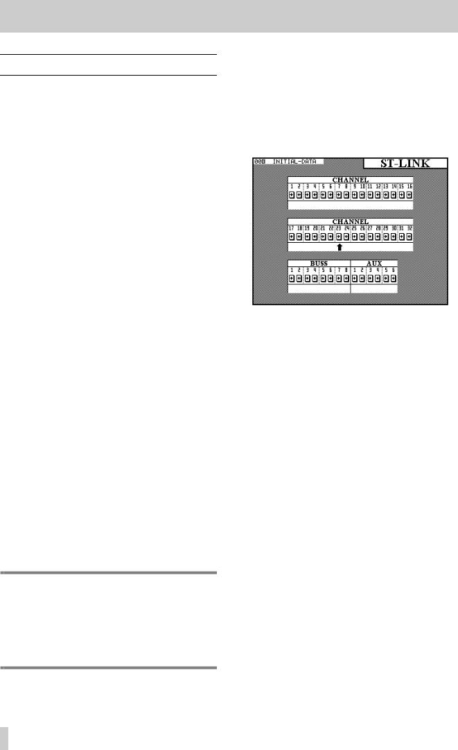
4 - Module operations—Stereo linking
4.2 Stereo linking
In unshifted mode, the GROUPING/ST LINK key allows the linking of channels as stereo pairs.
Only adjacent channels can be linked into stereo pairs, and the lower channel must be odd-numbered. In other words, while it is possible to link channels 1 and 2, it is not possible to link channels 1 and 3, nor is it possible to link channels 2 and 3.
Stereo linked channels allow the simultaneous setting and linking of the following module parameters:
•Input source
•Digital pad setting
•EQ settings
•Aux 1–6 send levels, on/off status and pre/post status
•Dynamics processor settings
•Logical fader level
•CUT switch status
•SOLO switch status
•Buss assignment
•Fader group and cut group assignments
•Automation mode settings.
In addition to the stereo linking of channels, the TMD4000 also allows the stereo linking of output busses 1 through 8, and Aux send busses 1 through 6. Again, only adjacent busses may be linked, and the lower buss of each buss pair must be odd-numbered.
When a pair of output busses is linked, the buss send levels and delay settings are linked.
When a pair of Aux sends is linked, the send levels are linked.
In cases where pan controls were previously available (channels), the pan controls are changed to balance controls and an image width control is added.
When channels are linked, the pan “gang” feature is no longer available.
NOTE
When a pair of channels or busses is linked, if the physical faders are not in identical positions before the link process, the “child” fader of the pair will rise to meet the other “parent” fader. This may cause a sudden rise in monitoring, etc. levels.
4.2.1Using the ST LINK key to link channels
To make a stereo link between two adjacent channels or busses, make sure the SHIFT indicator is off, and press the ST LINK key to show the screen below.
Use the cursor keys or the JOG dial to move the cursor (upward-pointing arrow—ø) to the pair of channels or busses whose link status is to be changed.
Press the ENTER key to change between separate channel status (ªº) and stereo linked status (ST LINK) of the channels or busses.
4.2.2 Using the SEL keys to link channels
See 3.3.6, “Select link” for details of the Select Link parameter. When this is set on, the SEL keys of channels may be used to create and remove stereo links, rather than the screen described above.
Note that the SEL keys have a different function when the GROUPING screen, described in 4.9, “Fader and cut groups”, is showing, and therefore stereo linking and unlinking cannot be carried out at that time.
Pressing and holding the SEL key of one of a valid pair of channels and busses and then pressing the SEL key of the other member of the pair will bring up a pop-up panel asking for confirmation to form the stereo link between the two channels or busses. Press ENTER to confirm, or a cursor key to cancel.
If the two channels or busses already form a stereo link, this procedure will bring up a pop-up panel asking for confirmation to break the link. Press ENTER to confirm, or a cursor key to cancel.
The status of stereo links between channels and busses can be verified at any time, using the screen described above.
4–2
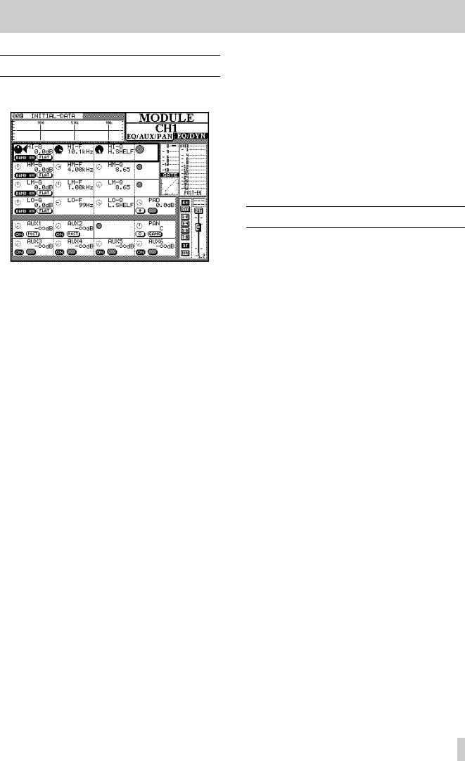
4 - Module operations—Equalization
4.3 Equalization
The first three PODs in the first four POD rows of the MODULE screen control the equalization.
As the equalization settings are changed, the graphical representation of the EQ response also changes.
The four EQ bands are named HI (high), HM (highmid), LM (low-mid) and LO (low). The HI and LO bands differ from the other two, as explained below.
The gain of the bands is between +15dB and -15 dB in 62 steps.
However, the high and low bands can be set to act as lowpass and highpass filters, respectively, by turning the gain to below the minimum -15dB setting.
If the gain is turned below -15dB on the HM and LM bands, they change to notch-type filters.
Each of the four EQ bands covers the same frequency range: 32Hz to 19kHz, selectable over a 112step range using POD 2.
The Q of each band (the frequency range over which it operates) can be set from 8.65 to 0.27 in 25 steps. The high and low bands can be set to provide shelving EQ, as opposed to peaking-type EQ.
Each band can be turned on and off using the left switch of POD 1.
The gain of each band can be flattened using the right switch of POD 1.
In order to bypass the equalization circuit for the module completely, the EQ key to the right of the display screen should be pressed. When the EQ is bypassed, the response curve at the top of the display is “grayed out” to show that EQ settings have no audible effect, but making adjustments using the
PODs will change the shape of the curve. When the EQ is brought back, these changes will take effect.
When two channels have been linked into a stereo pair, or when one of the two stereo inputs is selected, the changes made to the equalization affect both channels equally.
EQ settings, once made, may be stored in the EQ library for further recall. The way in which this is done is explained in the section of this manual dealing with the TM-D4000 libraries (8, “Library functions”).
4.4 Channel-to-buss assignments
There are two ways of assigning channels to the eight output busses, the stereo busses, or for direct output: using the dedicated ASSIGN key or from the MODULE screen.
4.4.1Using the MODULE screen for buss assignment
The status of the keys to the right of the display screen are shown: EQ, DYNAMICS, the buss and stereo assignment keys, and the direct out status (for input channels 1 through 16).
The function of the EQ and DYNAMICS keys are explained in the appropriate places (4.3, “Equalization” and 4.6, “Dynamics processor settings”).
The channel can be assigned to any combination of the eight output busses and the stereo output buss. Busses are selected in pairs (1–2, 3–4, 5–6, 7–8).
As with most analog consoles when a buss pair is selected, the odd-numbered buss of the pair corresponds to a hard left pan, and the even-numbered buss corresponds to a hard right pan. Anything in between will balance the channel signal proportionately between the two busses.
Input channels 1 through 16 (the integral analog inputs and the inputs of slot 1) can also be assigned as direct outs (DIR on this screen).
They are sent from the outputs which correspond to the input channel number, plus 16. In other words, input channel 1, when selected for direct out, is output from channel 17 (the first output channel of slot 2), channel 9 is output from channel 25 (the first output channel of slot 3), etc. If slots 2 and 3 are not fitted with interface cards, the DIRECT key will have no effect.
4–3
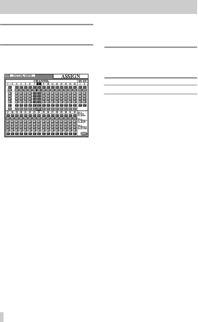
4 - Module operations—Aux sends
NOTE
The direct out setting is available for channels 1 through 16 only.
4.4.2Using the ASSIGN key for buss assignment
Press the ASSIGN key [10] to bring up the channel assignment screen.
The cursor keys are used to move the cursor to a particular channel and highlight the channel’s number at the top of the column.
Alternatively, the channel’s SEL key may be used to select a channel.
When a channel has been highlighted on this screen, pressing any of the following keys to the right of the display screen will change the assignment status of the selected channel: BUSS 1-2, BUSS 3-4, BUSS 5- 6, BUSS 7-8 and STEREO.
As with most analog consoles when a buss pair is selected, the odd-numbered buss of the pair corresponds to a hard left pan, and the even-numbered buss corresponds to a hard right pan. Anything in between will balance the channel signal proportionately between the two busses.
In addition, the EQ and DYN keys can be used to bypass the equalization and the dynamics processor for each channel, respectively.
There are three “global” on-screen buttons. The first of these (ALL BUSS CLEAR) is used to clear all buss (but not stereo) assignments. This may be used, either together with or independently from the last (ALL STEREO ASSIGN) when starting the mixdown in a multitrack recording session.
The second on-screen button, ALL STEREO CLEAR, clears all channel-to-stereo assignments.
The direct out of channels 1 through 16 can also be set in this screen (there are no on-screen representations of the direct out setting for channels 17 through 32, as this is not possible).
NOTE
When channels 1 through 16 are set to direct out, the signal appears in the output channel corresponding to the number of the input channel plus 16, as described above.
4.5 Aux sends
The MODULE screen can also be used to set the Aux send levels for a channel or pair of stereo linked channels. In addition, there are six dedicated AUX keys which allow the viewing and setting of the six Aux send levels of many channels from one screen.
4.5.1Using the MODULE screen to set send levels
The level of the signals sent from the channel to the six Aux sends are set and displayed on the bottom two rows of the MODULE EQ/AUX/PAN screen.
In an identical fashion to the dedicated Aux screens, the levels of the Aux sends can be set from -˚ dBto
10.0dB.
The left switches of the Aux PODs are used to turn the module’s Aux sends on and off.
Aux sends 1 and 2 can be selected as preor postfader, using the right switches of PODs 1 and 2 respectively.
When two modules have been linked into a stereo pair, or one of the two stereo inputs is selected, the Aux send levels apply to both channels in the pair.
When two Aux busses have been linked together into a stereo pair, the level control of the first (odd-num- bered) Aux buss is replaced by a pan control. The left switch of the corresponding POD becomes a centering switch.
4.5.2 Using AUX keys to set send levels
When one of the AUX keys is pressed and the Aux buss selected has not been made into a stereo linked pair with the adjacent Aux buss, two screens are available, each controlling 16 input channels. The
4–4
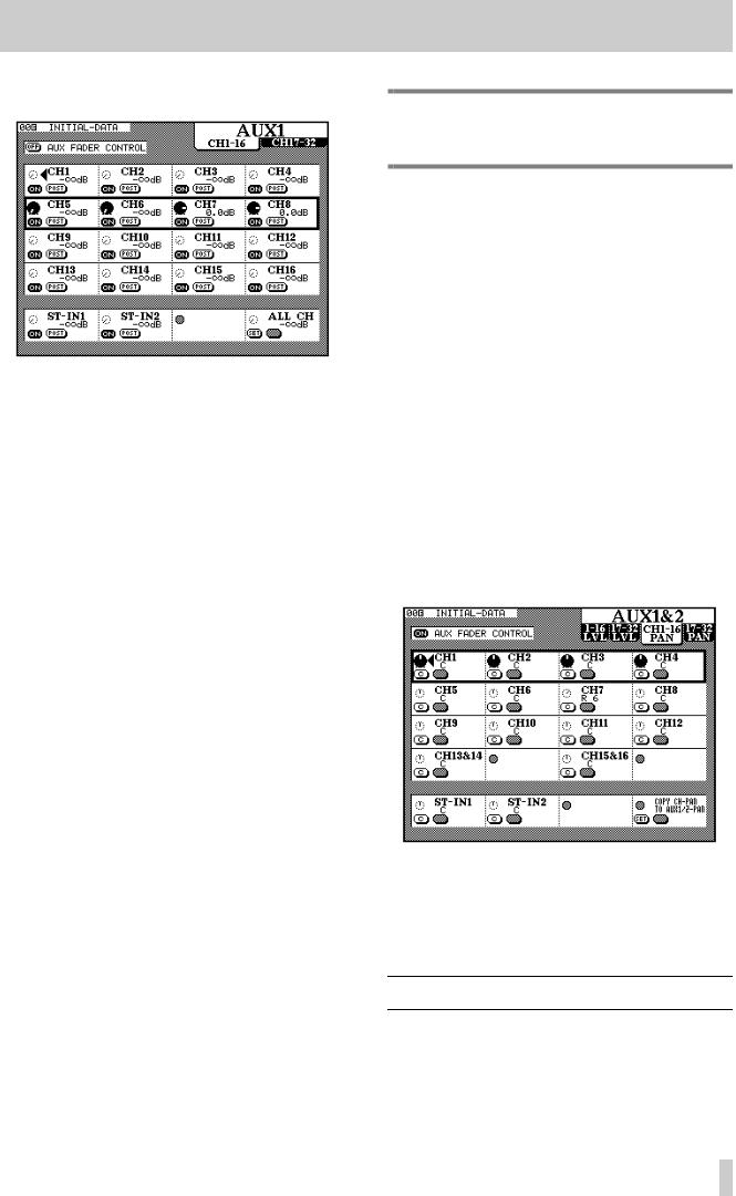
4 - Module operations—Dynamics processor settings
first screen controls channels 1–16 and the second controls channels 17–32.
Use the POD ROW CURSOR controls to move the “box” up and down, highlighting the channels which are to be edited.
The POD rotary controls adjust the level of the signal sent to the Aux buss.
This level can be adjusted from +10.0dB (relative to nominal) to -¢dB (minus infinity–full cut) in 128 steps.
The left POD switches control whether the Aux send signal from the selected channel is on or off.
For Aux busses 1 and 2, the right POD switch functions as a pre/post selector, allowing the pickoff point for the Aux send to be pre-fader or post-fader.
The pre-fader point is also before the cut and solo switches, as well as before the pan.
The bottom POD row of the screen provides controls for the two stereo inputs, as well as a global control control. Turn the fourth POD’s knob to select between -¢dB (full cut), 0dB (nominal), AUX OFF, AUX ON and (for Aux sends 1 and 2 only) PRE and POST. Use the left POD switch to SET the value selected using the knob for all channels.
AUX Fader control : There is also one important on-screen button at the top of the screen: the
AUX FADER CONTROL button.
When this option is selected using the cursor and ENTER keys, the faders will move to match the Aux send levels of the currently-selected Aux buss, and the currently-selected LAYER STATUS indicator ([3]) will flash to show that the faders are no longer controlling channel and module levels.
The PODs are also active, and moving a POD knob will also move the appropriate fader to reflect the new level.
NOTE
This is the only time that the ST IN faders change function.
If two channels have been linked as a stereo pair (see 4.2, “Stereo linking”), only the left POD of the pair is active.
Stereo linking and AUX sends : If two Aux sends have been linked together as a stereo pair, there are now four screens available when an AUX key is pressed.
As well as the level screens for the two sets of 16 channels (identical to the one described above), there are also two pan screens; one for each set of 16 channels.
In these screens, the POD rotary controls are used to adjust the relative level of the signal sent to the two linked Aux busses.
The left switch of the PODs is used to center the pan control for the channel.
In the case of a stereo linked pair of channels, the left POD only is active. The pan control changes to a balance control. This can be centered using the left POD switch in the same way as a mono channel.
The left switch of POD 4 in the last row is used to copy the channel pan settings of all channels to the pan settings for the selected Aux send pair. In this way, the main “buss” image of the channels is preserved in the Aux sends.
4.6 Dynamics processor settings
These settings are accessed by pressing the MODULE key for the selected channel until the EQ/DYN screen is shown, or alternatively by pressing the
4–5
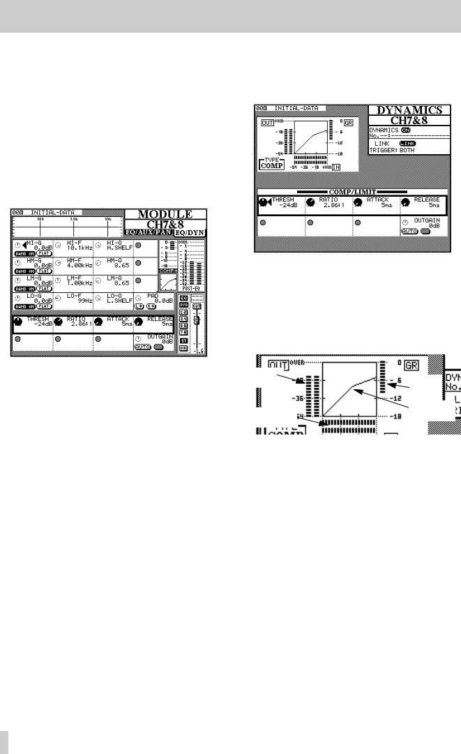
4 - Module operations—Dynamics processor settings
DYNAMICS key to recall the DYNAMICS screen for the selected module.
4.6.1 Assigning a processor to a module
This is described in full in 8.2.2, “Recalling a library entry”. Briefly, the module is selected, the dynamics processor library screen is entered, and the desired processor settings are recalled from the library.
4.6.2Using the MODULE key to make dynamics processor settings
The equalization controls on this screen are identical to those on the other MODULE screen.
However, the two lowest POD rows are used to control the dynamics processor. The exact assignment of the PODs to controls depends on whether a gate or a compressor (shown on the small on-screen level diagram as GATE or COMP) has been recalled from the library into this channel, as described below.
To enable and disable the selected channel’s dynamics processor, use the DYNAMICS key to the right of the display screen. The on-screen DYN indicator in the “button strip” at the lower left of the screen changes to reflect the on/off status.
Stereo linked channels and stereo inputs may share the same dynamics processor settings. However, see the explanation of the DYNAMICS key immediately following this, for further information regarding stereo linking of dynamics processors.
4.6.3Using the DYNAMICS key to make dynamics processor settings
With the desired channel selected, press the mixer DYNAMICS key (not the library DYNAMICS key).
The information at the upper left of the screen includes:
•The dynamics processor’s gain reduction meter
•A graphical representation of the dynamics processor’s gain structure. An example of the way a pair of stereo linked processors are shown on screen is given here:
Output
levels |
Gain |
|
reduction |
||
|
||
Input levels |
Compressor |
|
“knee” |
||
|
4.6.4 Compressor/limiter settings
Both the MODULE and DYNAMICS screens allow the same parameters to be set.
•Threshold (THRESH), controlled by the POD 1 knob, and variable from -48dB to 0dB in 49
1dB steps.
•Compression ratio (RATIO), controlled by the POD 2 knob, and variable from 1:1 to ˚ :1 (infinite compression) in 21 steps.
•Attack time (ATTACK), controlled by the POD
3knob, and variable from 0ms to 125ms in
1ms steps.
•Release time (RELEASE), controlled by the POD 4 knob, and variable from 5ms to 5.0s in 100 steps.
•Output gain (OUTGAIN), controlled by the POD 4 knob on the last row. Variable from -24dB to +24dB in 1 dB steps.
4–6

4 - Module operations—Pan and balance
•Auto make-up (AUTO), controlled by the left switch of POD 4 below the output gain. This is used, together with the output gain setting for automatic optimum level control if the compression settings have resulted in gain reduction.
4.6.5 Gate settings
Both the MODULE and DYNAMICS screens allow the same parameters to be set.
•Threshold (THRESH), controlled by the POD 1 knob, allows the setting of the threshold at which the gate will open. Variable from -80dB to 0dB in 1 dB steps.
•Range (RANGE), controlled by the POD 2 knob, sets the gate range, from 0dB to 60dB in 1dB steps.
•Hysteresis (HYST), controlled by the POD 3 knob, from 0dB to 24dB in 1dB steps.
•Gate attack time (ATTACK), controlled by the POD 1 knob on the last row. Variable from 0ms to 125ms in 1 ms steps.
•Gate hold time (HOLD), controlled by the POD 2 knob on the last row. Variable from 0ms to 990ms in 100 steps.
•Gate decay time (DECAY), controlled by the POD 3 knob on the last row. Variable from 50ms to 5.0s in 100 steps.
4.6.6 Linked channels
LINK allows the linking of two processors assigned to two adjacent channels (the “left” channel of the pair must be odd-numbered).
This link is automatically made, and cannot be turned off, when two modules have been stereo linked (or for the stereo inputs or the stereo out).
Trigger source (TRIGGER) is only valid when two processors are linked. This option (selected using the ENTER key or JOG dial) allows the triggering for both processors to be initiated by L-ch (left channel), R-ch (right channel) or BOTH (both channels act as triggers—in other words, the first channel to be triggered will automatically activate the second channel’s processor).
NOTE
The two ST IN channels and the stereo out buss do not allow trigger selection, and are fixed at the BOTH setting.
4.7 Pan and balance
As well as using the MODULE screen to adjust the pan of a module (or the balance of a stereo pair of modules), there is a dedicated PAN/BAL screen, allowing the viewing and setting of many modules simultaneously.
4.7.1Using the MODULE key to set pan and balance
Pan and balance controls are only available in the
EQ/AUX/PAN MODULE screen, not the
EQ/DYN module screen.
Mono modules : The fourth POD rotary control on the fifth row is a pan control, when the module is a mono module.
The pan settings are L45 (hard left), through C (center) to R45 (hard right).
The left switch of this POD is a centering switch.
For odd-numbered channels only, the right switch of this POD is a gang switch, allowing this pan control to be ganged with the pan control of the next channel.
Stereo modules : When two channels have been linked into a stereo pair, or when one of the stereo inputs is selected, the pan control changes to a balance control.
The left switch of the POD is a centering switch.
The third POD becomes an “image” control, which determines the width of the stereo image produced by the two channels. Turning the knob to the “center” allows “pinpointing” of the image (L+Rmono), full width (STEREO, fully counterclockwise) or full width, with the positions of the two linked channels reversed with respect to normal (REVERSE, fully clockwise). Intermediate positions are represented as percentage figures preceded by ST (stereo) or REV (reverse), with ST 98% following immediately after STEREO, and REV 98% immediately after REVERSE.
The switches of the third POD allow either the left or the right channel of the pair to be selected as a mono source (the image control is then disabled).
If a surround mode, rather than the stereo mode, has been selected, surround positioning control is not possible from the MODULE screen. Use the dedicated PAN/BAL key instead. See 6, “Surround modes” for details.
4–7
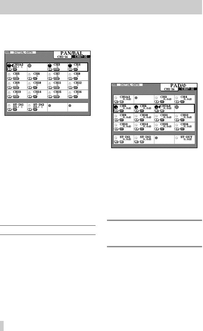
4 - Module operations—Pad and phase(Φ)
4.7.2 Using the PAN/BAL key
Pressing the PAN/BAL key brings up a display screen allowing the viewing and setting of a number of the pan and balance parameters for a number of different modules:
There are two screens, the first for the input modules 1 through 16, and the second for input modules 17 through 32. The stereo inputs are visible and their parameters may be adjusted in both screens.
Press the PAN/BAL key repeatedly to cycle between these screens.
In the screen shown above, channels 1 and 2 are linked into a stereo pair.
The left switch of each POD acts as a centering switch, and the right switch of odd-numbered mono modules allows “ganging” of two mono inputs.
The POD for the even-numbered switch of a stereo linked pair is disabled—the odd-numbered pod must be used here.
Note that the image control is not available from this screen—this parameter can be set from the MODULE screen only.
4.8 Pad and phase(Φ)
The digital pad and phase of the input signal may be adjusted from the MODULE screen, as well as through a dedicated screen, allowing the viewing and adjustment of the parameters for many modules.
4.8.1 Using the MODULE screen
In the EQ/AUX screen, the knob of the fourth POD of the fourth row is used to adjust the digital pad. The pad values are from 0 dB to –36 dB in 0.5 dB steps.
4.8.2 Using the PAD/phase key
There are two screens available for control of the input modules’ digital pads and phase settings. The first screen controls channels 1 through 16, and the second controls channels 17 through 32. Both control the two stereo inputs and the stereo output.
These settings are made using the POD knobs to control the digital pads, and the POD left switches to control the input channel phase.
The possible pad parameter values are the same as for the MODULE screen.
The two stereo inputs, and any channels that have been linked into a stereo pair, can have the phase set independently for each channel of the pair, allowing compensation for mis-wired microphone pairs, etc.
The phase of the stereo outputs cannot be changed, though a pad is available for the stereo output.
NOTE
This digital pad is not related to the analog pad which forms part of the analog input circuitry of channels 1 through 8.
4–8
Loading...