


Working Instruction, Mechanical
Working Instruction, Mechanical
Applicable for C905
CONTENTS
1 Introduction .............................................................................. |
4 |
|
1.1 |
Equipment................................................................................. |
5 |
1.2 |
General cautions ...................................................................... |
6 |
1.3 |
Adhesives ................................................................................. |
6 |
2 Disassembly ............................................................................. |
7 |
|
2.1 |
Overview ................................................................................... |
8 |
2.2 |
Battery Cover & Battery........................................................... |
9 |
2.3 |
Foil Flip Inner.......................................................................... |
10 |
2.4 |
Keyboard................................................................................. |
10 |
2.5 |
Cap Plastic RF Numeric Keyboard & Cap Numeric |
|
|
Keyboard................................................................................. |
11 |
2.6 |
Cover Flip Front...................................................................... |
12 |
2.7 |
Display 2.41 TFT ..................................................................... |
13 |
2.8 |
LCD Support Sheet ................................................................ |
13 |
2.9 |
PBA Key Flex Flip Complete ................................................. |
14 |
2.10 Cover Rear Assembly ............................................................ |
16 |
|
2.11 Cover Base Rear Assembly................................................... |
17 |
|
2.12 Main PBA................................................................................. |
18 |
|
2.13 Loudspeaker Assembly......................................................... |
20 |
|
2.14 Flash Complete and Camera 8MP......................................... |
21 |
|
3 Replacements......................................................................... |
23 |
|
3.1 |
Battery Cover & Battery......................................................... |
24 |
3.2 |
Cover Flip Front Assembly.................................................... |
24 |
3.3 |
Cover Base Rear Assembly................................................... |
24 |
3.4 |
Flash Complete....................................................................... |
24 |
3.5 |
PBA Key Flex Flip Complete ................................................. |
24 |
3.6 |
Slider FPC Assy...................................................................... |
24 |
3.7 |
Cover Rear Assembly ............................................................ |
24 |
3.8 |
Carrier Base Assembly.......................................................... |
25 |
3.9 |
Camera 8 MP........................................................................... |
25 |
3.10 Foil Flip Inner.......................................................................... |
25 |
|
3.11 LCD Support Sheet ................................................................ |
25 |
|
3.12 Loudspeaker Assembly......................................................... |
25 |
|
3.13 Screw 4.0x1.4.......................................................................... |
25 |
|
3.14 Screw 2.3x1.4.......................................................................... |
25 |
|
1218-1731 Rev 3 |
|
1(87) |
Company Internal ©Sony Ericsson Mobile Communications AB |
|
|

Working Instruction, Mechanical |
|
3.15 Screw Torx 5.3x1.6 ................................................................. |
26 |
3.16 Screw Torx 5.0x1.6 ................................................................. |
26 |
3.17 Screw Philips M1.4x1.7.......................................................... |
26 |
3.18 Cap Plastic RF Keyboard Numeric ....................................... |
26 |
3.19 Cap Numeric Keyboard.......................................................... |
26 |
3.20 Foil Adhesive Single Side 0.15 mm Flip Tape ..................... |
26 |
3.21 Display 2.41 TFT ..................................................................... |
27 |
3.22 Cover Flip Inner Metal............................................................ |
27 |
3.23 Cap Reinforcement Plug (Right and Left)............................ |
28 |
3.24 Numeric Key Foil .................................................................... |
29 |
3.25 Keyboard Navigation ............................................................. |
31 |
3.26 Key A/B Left ............................................................................ |
32 |
3.27 Key A/B Right ......................................................................... |
33 |
3.28 Co Brand Label....................................................................... |
34 |
3.29 Key Volume............................................................................. |
35 |
3.30 Key Mode ................................................................................ |
35 |
3.31 Key Camera............................................................................. |
36 |
3.32 M2 Lid37 |
|
3.33 Microphone Gasket ................................................................ |
38 |
3.34 BT/WLAN Antenna ................................................................. |
39 |
3.35 Left Sidepanel......................................................................... |
40 |
3.36 Right Sidepanel Bottom......................................................... |
41 |
3.37 Right Sidepanel Top............................................................... |
42 |
3.38 Ear Speaker............................................................................. |
43 |
3.39 Vibrator.................................................................................... |
44 |
3.40 Light GU Navigation............................................................... |
45 |
3.41 Dome Foil Flip......................................................................... |
46 |
3.42 PBA Key Flex Flip Complete ................................................. |
48 |
3.43 Shield Can Lid Flip ................................................................. |
49 |
3.44 Cushion 1,0mm1,3x5,1,0 Conductive................................... |
50 |
3.45 Foil Adhesive 0.048 mm Flex Flip......................................... |
51 |
3.46 Foil Adhesive Conductive 0.05 mm protection tape, front.52 |
|
3.47 Foil Adh Conduct GPS ESD protection tape ....................... |
53 |
3.48 Foil Adhesive Double Side GPS Shieldcan ......................... |
54 |
3.49 Foil Adhesive Double Side A/B Flex Tape ........................... |
55 |
3.50 Foil Adhesive Double Side GPS Antenna ............................ |
56 |
3.51 Shield can lid, Vera ................................................................ |
56 |
3.52 Shield can lid, regulator......................................................... |
57 |
3.53 Shield can lid, Kajsa............................................................... |
57 |
3.54 Shield can lid, WLAN ............................................................. |
58 |
3.55 Shield Can Lid, Camera ......................................................... |
58 |
3.56 Liquid Intrusion Indicator (1 and 2) ...................................... |
59 |
3.57 Foil Adhesive LCD Support, left ........................................... |
61 |
3.58 Foil Adhesive LCD Support, right......................................... |
62 |
3.59 Light Gu Numeric ................................................................... |
63 |
3.60 Hinge Slide Mechanism ......................................................... |
65 |
1218-1731 Rev 3 |
2(87) |
Company Internal ©Sony Ericsson Mobile Communications AB |
|

|
|
Working Instruction, Mechanical |
|
|
3.61 Label 67 |
|
|
4 |
Reassembly ............................................................................ |
68 |
|
|
4.1 |
Overview ................................................................................. |
69 |
|
4.2 |
Flash Complete and Camera 8 MP........................................ |
70 |
|
4.3 |
Loudspeaker Assembly......................................................... |
72 |
|
4.4 |
Main PBA................................................................................. |
72 |
|
4.5 |
Cover Base Rear Assembly................................................... |
76 |
|
4.6 |
Cover Rear Assembly ............................................................ |
77 |
|
4.7 |
PBA Key Flex Flip Complete ................................................. |
77 |
|
4.8 |
LCD Support Sheet ................................................................ |
80 |
|
4.9 |
Display 2.41 TFT ..................................................................... |
81 |
|
4.10 Cover Flip Front...................................................................... |
82 |
|
|
4.11 Cap Plastic RF Numeric Keyboard & Cap Numeric |
|
|
|
|
Keyboard................................................................................. |
83 |
|
4.12 Keyboard................................................................................. |
84 |
|
|
4.13 Foil Flip Inner.......................................................................... |
85 |
|
|
4.14 Battery Cover & Battery......................................................... |
85 |
|
5 Country of Origin Barcodes for Brazil/VIVO Labels............ |
86 |
||
6 |
Revision history ..................................................................... |
87 |
|
1218-1731 Rev 3 |
3(87) |
Company Internal ©Sony Ericsson Mobile Communications AB |
|

Working Instruction, Mechanical
1 Introduction
1218-1731 Rev 3 |
4(87) |
Company Internal ©Sony Ericsson Mobile Communications AB |
|
Working Instruction, Mechanical
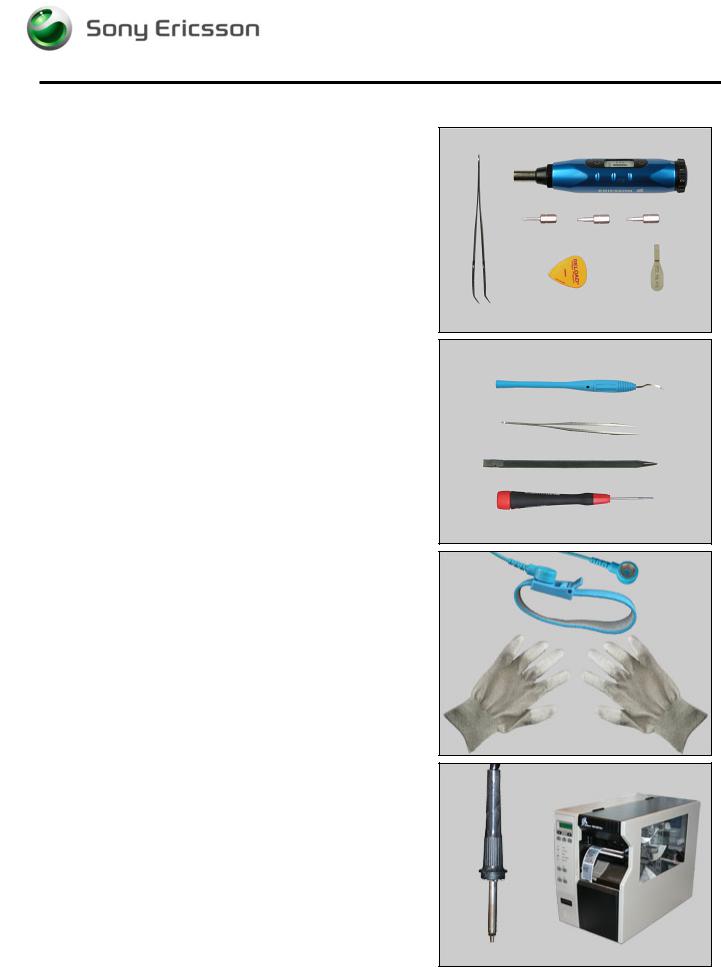
1.1 Equipment
SPECIAL TOOLS
Special tools text: |
|
|
• |
NTZ122459 |
Torque Screwdriver (or equivalent) |
• |
NTZ122288 |
Bit (T6) |
• |
NTZ112478 |
Bit (T5) |
• |
NTZ1121052 |
Bit(JCIS No 0) |
• |
NTZ112302/2 |
Front opening tool |
•NTZ112521 Flex film assembly tool
•NTZ112590 Plectrum/SVC & Repair
STANDARD TOOLS
Standard tools text:
•Dentist hook
•ESD tweezers
•Nylon Pointer
•Screwdriver
ESD EQUIPMENT
Protect the phone from ESD damages whenever it has been opened by using:
•ESD-wristband
•ESD-gloves
LABEL EQUIPMENT
The following special equipment is required when replacing or installing a new label:
•Hot air flow solder station
•Zebra printer connected to computer
1218-1731 Rev 3 |
5(87) |
Company Internal ©Sony Ericsson Mobile Communications AB |
|

Working Instruction, Mechanical
1.2 General cautions
The following cautions are considered to be generic for all phone models and will not be repeated in the Disassembly, Replacements and Reassembly sections:
•SWITCH OFF THE PHONE AND REMOVE ANY MEMORY STICK BEFORE THE START OF THE DISASSEMBLY!
•KEEP ALL CONTACT SURFACES CLEAN!
•BE CAREFUL WHEN USING TOOLS LIKE THE DENTIST HOOK, TWEEZERS, OPENING TOOLS, GUITAR PICK
ETC. TO AVOID SCRATCHES OR DAMAGES TO THE EXTERIOR AND INTERIOR PARTS OF THE PHONE!
•BE CAREFUL NOT TO DAMAGE ANY CONTACT SPRINGS!
•REMEMBER TO REMOVE THE PROTECTION FOILS ON NEW PARTS SUCH AS THE FRONT COVER AND LCD!
•NEVER TOUCH THE DISPLAY GLASS!
•USE AIR BLOW EQUIPMENT TO KEEP THE FRONT WINDOW AND DISPLAY MODULE DUST FREE!
1.3 Adhesives
Use a dentist hook and/or the tweezers to remove old adhesives.
Clean the surface with isopropyl alcohol before attaching new adhesives.
1218-1731 Rev 3 |
6(87) |
Company Internal ©Sony Ericsson Mobile Communications AB |
|

Working Instruction, Mechanical
2 Disassembly
When you are going to replace a part being listed in Replacements, the instruction of that section usually begins by directing you to this Disassembly section with a specification of the instructions you have to carry out in order to disassemble the phone as far as needed before returning to Replacements for the actual replacement.
REPLACEMENTS
Start |
Contents |
|
page |
||
|
||
|
|
DISASSEMBLY |
REASSEMBLY |
 Done
Done
1218-1731 Rev 3 |
7(87) |
Company Internal ©Sony Ericsson Mobile Communications AB |
|
Working Instruction, Mechanical
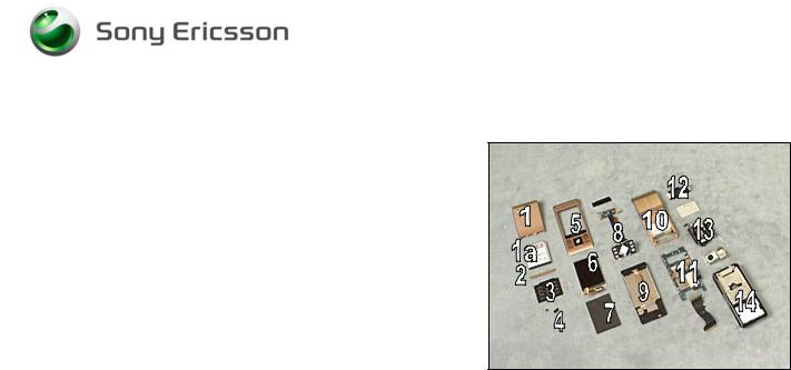
2.1 Overview
The disassembly is done in the following sequence:
1. Battery Cover
1a. Battery
2. Flip Inner
3. Keyboard
4. Cap Plastic RF Numeric Keyboard & Cap Numeric
Keyboard
5.Cover Flip Front
6.Display 2.41 TFT
7.LCD Support Sheet
8.PBA Key Flex Flip Complete
9.Cover Rear Assembly
10.Cover Base Rear Assembly
11.Main PBA
12.Loudspeaker Assembly
13.Flash Complete and Camera 8MP
14.Carrier Base Assembly
1218-1731 Rev 3 |
8(87) |
Company Internal ©Sony Ericsson Mobile Communications AB |
|
Working Instruction, Mechanical
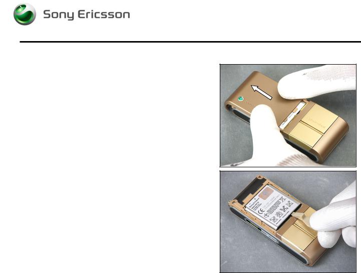
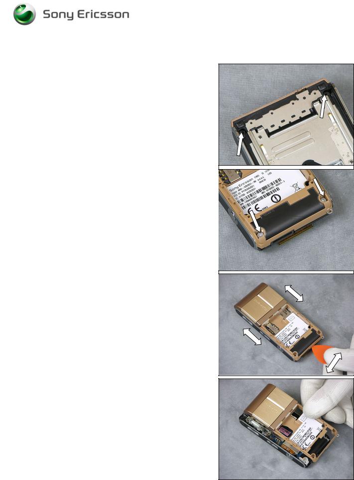
2.2Battery Cover & Battery
Remove the Battery Cover.
Remove the Battery.
1218-1731 Rev 3 |
9(87) |
Company Internal ©Sony Ericsson Mobile Communications AB |
|

Working Instruction, Mechanical
2.3 Foil Flip Inner
Use a pair of ESD tweezers to remove the Flip Inner.
Use a Screwdriver with JCIS Bit to remove the two Screws 4.0x1.4.
2.4 Keyboard
Use a Screwdriver to loosen the keyboard from the opposite side
Use a Flex Film Assembly Tool to remove the Keyboard
1218-1731 Rev 3 |
10(87) |
Company Internal ©Sony Ericsson Mobile Communications AB |
|
Working Instruction, Mechanical
2.5Cap Plastic RF Numeric Keyboard & Cap Numeric Keyboard
Use a Screwdriver to remove the Cap Plastic RF Keyboard
Numeric on the opposite side.
Use Screwdriver to remove the Cap Numeric keyboard on the opposite side.
1218-1731 Rev 3 |
11(87) |
Company Internal ©Sony Ericsson Mobile Communications AB |
|

Working Instruction, Mechanical
2.6 Cover Flip Front
Use your fingers to slide and position the Cover Flip Front to make the two Screws 2.3x1.4 visible through the two holes in the Cover Base Rear Assembly.
Use a Screwdriver with JCIS Bit to remove the two Screws 2.3x1.4.
Use a Guitar Pick to loosen the Cover Flip Front on both sides.
Use your fingers to remove the Cover Flip Front.
1218-1731 Rev 3 |
12(87) |
Company Internal ©Sony Ericsson Mobile Communications AB |
|
Working Instruction, Mechanical
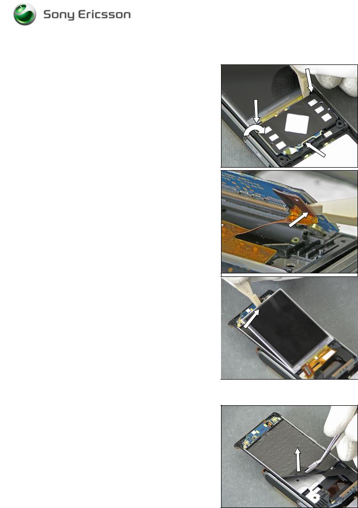
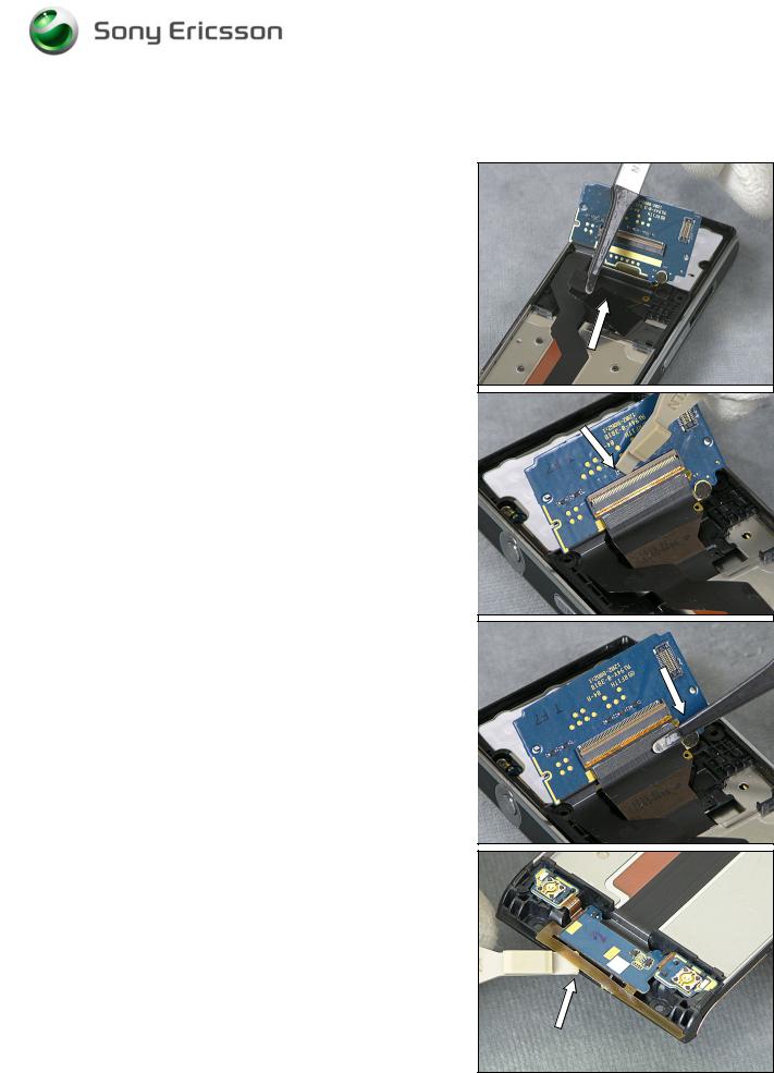
2.7 Display 2.41 TFT
Locate the three snap hooks and use a Front Opening Tool to release the PCB-part of the PBA Key Flex Flip Complete.
Use a Front Opening Tool to disconnect the LCD FPC
Connector
BE VERY CAREFUL WHEN BENDING THE PCB-PART OF THE
KEY FLEX FLIP
BE VERY CAREFUL NOT TO DAMAGE THE DISPLAY FLEX!
Use a Front Opening Tool to remove the Display 2.41 TFT.
2.8 LCD Support Sheet
Use a blunt pair of Tweezers to remove the LCD Support
Sheet.
1218-1731 Rev 3 |
13(87) |
Company Internal ©Sony Ericsson Mobile Communications AB |
|
Working Instruction, Mechanical
2.9 PBA Key Flex Flip Complete
Use a Flex Film Assembly Tool to remove the Foil Adhesive
Single Side 0.15 mm Flip Tape
Use a Front Opening Tool to unsnap the PBA Key Flex Flip
Complete connector
Use a Flex Film Assembly Tool to disconnect the Slider
FPC Assy from the PBA Key Flex Complete
Use a Front Opening Tool to loosen the GPS Antenna.
1218-1731 Rev 3 |
14(87) |
Company Internal ©Sony Ericsson Mobile Communications AB |
|
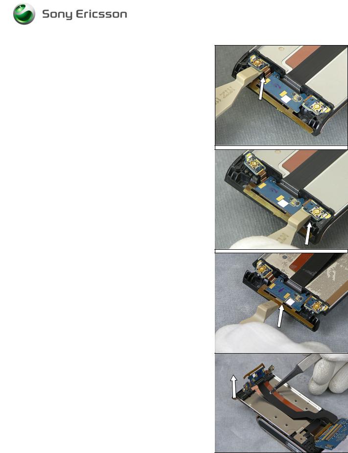
Working Instruction, Mechanical
Use a Front Opening Tool to loosen the Key B part of the
Board.
Use a Front Opening Tool to loosen the Key A part of the
Board.
Use a Front Opening Tool to loosen the GPS part of the
Board.
Use a Flex Film Assembly Tool to remove the PBA Key
Flex Flip Complete
1218-1731 Rev 3 |
15(87) |
Company Internal ©Sony Ericsson Mobile Communications AB |
|
Working Instruction, Mechanical
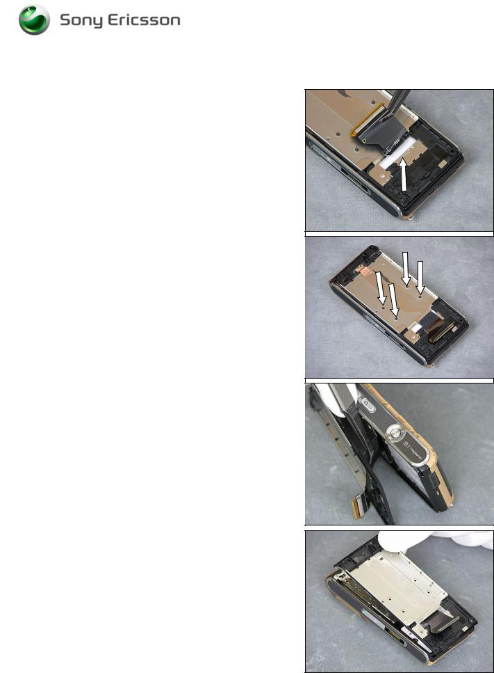
2.10 Cover Rear Assembly
Use a Flex Film Assembly Tool to loosen the Slider PPC
Assy from the Cover Rear Assembly
Use a Screwdriver with JCIS Bit to remove the four Flat
Head M1.4x1.7
Use a Flex Film Assembly Tool to loosen the Slider PPC
Assy from the back of the Cover Rear Assembly
Use your fingers to remove the Cover Rear Assembly
1218-1731 Rev 3 |
16(87) |
Company Internal ©Sony Ericsson Mobile Communications AB |
|
Working Instruction, Mechanical
2.11 Cover Base Rear Assembly
Use a Screwdriver with T5 Bit to remove the two Screws
Torx 5.0x1.6.
Use a Screwdriver with T6 Bit to remove the two Screws
Torx 5.3x1.6.
Use a Guitar Pick to loosen the Cover Base Rear Assembly on three sides
Use your fingers to remove the Cover Base Rear Assembly.
1218-1731 Rev 3 |
17(87) |
Company Internal ©Sony Ericsson Mobile Communications AB |
|
Working Instruction, Mechanical
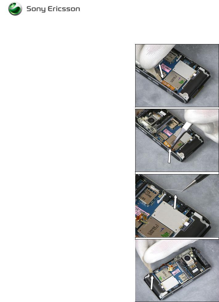
2.12 Main PBA
Use a Front Opening Tool to disconnect the Numeric Key
Foil Connector from the Main PBA
Use a Flex Film Assembly Tool to pull the Numeric Key Foil out of the camera key switch supporter.
Use a Pair of ESD Tweezers to loosen the BT/WLAN
Antenna
BE VERY CAREFUL NOT TO DAMAGE THE MAIN PBA SWITCHES
WHEN LOOSENING THE MAIN PBA!
Use a Front Opening Tool to bend the Carrier Base
Assembly away from the Main PBA and loosen the Main
PBA.
1218-1731 Rev 3 |
18(87) |
Company Internal ©Sony Ericsson Mobile Communications AB |
|
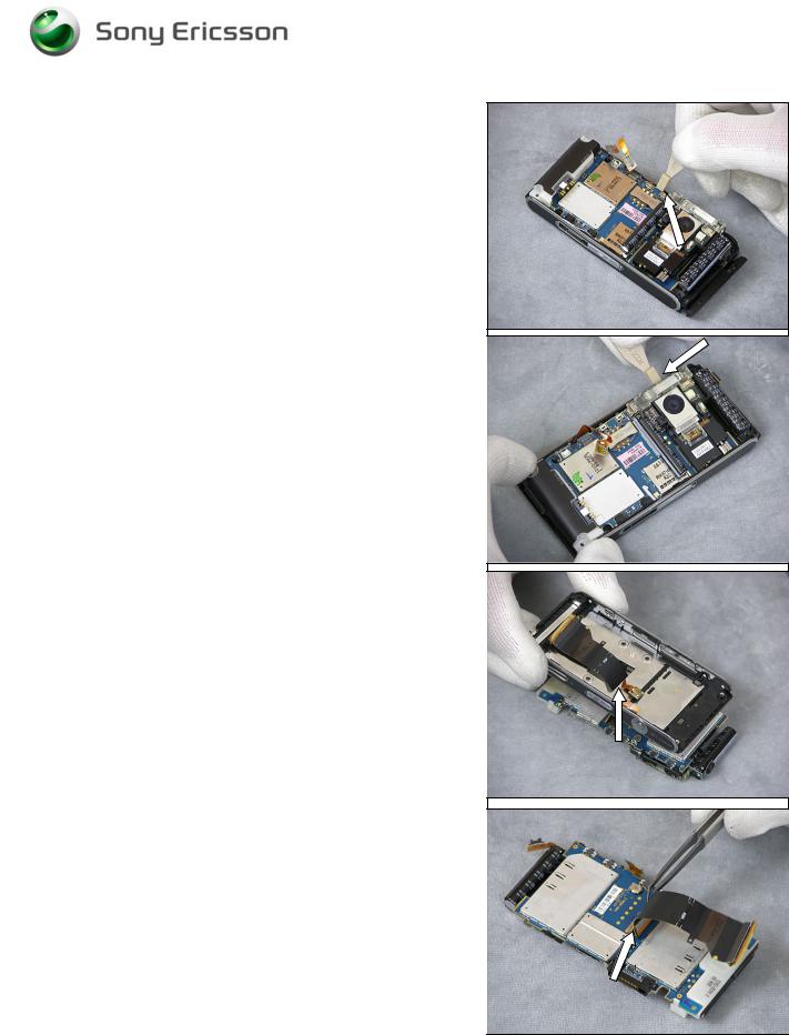
Use a Front Opening Tool to bend the Carrier Base Assembly away from the Main PBA and loosen the Main PBA.
Working Instruction, Mechanical
BE VERY CAREFUL NOT TO DAMAGE THE MAIN PBA SWITCHES
WHEN REMOVING THE MAIN PBA!
Use a Front Opening Tool to bend the Carrier Base
Assembly away from the Main PBA and loosen the Main
PBA.
BE VERY CAREFUL NOT TO DAMAGE THE SLIDER FPC ASSY!
Use your fingers to gently thread the Slider FPC Assy through the gap
Use A Flex Film Assembly Tool to Loosen the Slider FPC
Assy Adhesive from the 100 pin FPC connector
BE VERY CAREFUL NOT TO DAMAGE THE SLIDER FPC ASSY!
1218-1731 Rev 3 |
19(87) |
Company Internal ©Sony Ericsson Mobile Communications AB |
|
Working Instruction, Mechanical
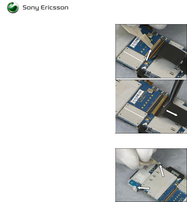
Use a Front Opening Tool to unhook the board to flex connector from the Main PBA.
Use a Flex Film Assembly Tool to remove the Slider FPC
Assy from the Main PBA
BE VERY CAREFUL NOT TO DAMAGE THE SLIDER FPC ASSY!
2.13 Loudspeaker Assembly
Use a Front Opening Tool to release the snap hooks and remove the Loudspeaker Assembly.
1218-1731 Rev 3 |
20(87) |
Company Internal ©Sony Ericsson Mobile Communications AB |
|

Working Instruction, Mechanical
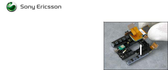
2.14 Flash Complete and Camera 8MP
Use a Dentist Hook to remove the Shield Can Lid, Camera
Use a Front Opening Tool to disconnect the Camera
Connector from the Main PBA
Use a Front Opening Tool to release the five snap hooks
Turn over the Main PBA and use a Front Opening Tool to disconnect the Flash Complete from the Main PBA
1218-1731 Rev 3 |
21(87) |
Company Internal ©Sony Ericsson Mobile Communications AB |
|
Working Instruction, Mechanical
Use your fingers to gently remove the Camera 8MP from the Flash Complete
1218-1731 Rev 3 |
22(87) |
Company Internal ©Sony Ericsson Mobile Communications AB |
|
Working Instruction, Mechanical
3 Replacements
Search for the part to be replaced on the Contents page and go to that instruction to be found in this
Replacements section.
The instruction usually begins by directing you to the Disassembly section with a specification of the instructions you have to carry out in order to disassemble the phone as far as needed before the actual replacement.
Go back to this Replacements section and carry out the instruction.
The instruction usually ends by directing you to the Reassembly section with a specification of the instructions you have to carry out in order to reassemble the phone.
REPLACEMENTS
Start |
Contents |
|
page |
||
|
||
|
|
DISASSEMBLY |
REASSEMBLY |
 Done
Done
1218-1731 Rev 3 |
23(87) |
Company Internal ©Sony Ericsson Mobile Communications AB |
|

Working Instruction, Mechanical
3.1 Battery Cover & Battery
Follow the 2.2 Disassembly instructions!
Replace Battery Cover and/or Battery
Follow the 4.14 Reassembly instructions!
3.2 Cover Flip Front Assembly
Follow the 2.2 – 2.6 Disassembly instructions!
Replace Cover Flip Front Assembly
Follow the 4.10 – 4.14 Reassembly instructions!
3.3 Cover Base Rear Assembly
Follow the 2.2 – 2.11 Disassembly instructions!
Replace Cover Base Rear Assembly
Follow the 4.5 – 4.14 Reassembly instructions!
3.4 Flash Complete
Follow the 2.2 – 2.14 Disassembly instructions!
Replace Flash Complete
Follow the 4.2 – 4.14 Reassembly instructions!
3.5 PBA Key Flex Flip Complete
Follow the 2.2 – 2.9 Disassembly instructions!
Replace Key Flex Flip Complete
Follow the 4.7 – 4.14 Reassembly instructions!!
3.6 Slider FPC Assy
Follow the 2.2 – 2.12 Disassembly instructions!
Replace Slider FPC Assy
Follow the 4.4 – 4.14 Reassembly instructions!
3.7Cover Rear Assembly
Follow the 2.2 – 2.10 Disassembly instructions!
Replace Cover Rear Assembly
Follow the 4.6 – 4.14 Reassembly instructions!
1218-1731 Rev 3 |
24(87) |
Company Internal ©Sony Ericsson Mobile Communications AB |
|

Working Instruction, Mechanical
3.8 Carrier Base Assembly
Follow the 2.2 – 2.12 Disassembly instructions! And 3.29-3.31, 3.34 – 3.36, 3.62 Replacement Instructions!
Replace Carrier Base Assembly
Follow the 4.4 – 4.14 Reassembly instructions! And 3.29-3.31, 3.34 – 3.36, 3.62 Replacement Instructions!
3.9 Camera 8 MP
Follow the 2.2 – 2.14 Disassembly instructions!
Replace Camera 8 MP
Follow the 4.2 – 4.14 Reassembly instructions!
3.10 Foil Flip Inner
Follow the 2.2 – 2.3 Disassembly instructions!
Replace Foil Flip Inner
Follow the 4.13 – 4.14 Reassembly instructions!
3.11 LCD Support Sheet
Follow the 2.2 – 2.8 Disassembly instructions!
Replace LCD Support Sheet
Follow the 4.8 – 4.14 Reassembly instructions!
3.12 Loudspeaker Assembly
Follow the 2.2 – 2.13 Disassembly instructions!
Replace Loudspeaker Assembly
Follow the 4.3 – 4.14 Reassembly instructions!
3.13 Screw 4.0x1.4
Follow the 2.2 – 2.3 Disassembly instructions!
Replace Screw 4.0x1.4 (torque 11Ncm)
Follow the 4.13 – 4.14 Reassembly instructions!
3.14 Screw 2.3x1.4
Follow the 2.2 – 2.6 Disassembly instructions!
Replace Screw 2.3x1.4 (torque 11Ncm)
Follow the 4.10 – 4.14 Reassembly instructions!
1218-1731 Rev 3 |
25(87) |
Company Internal ©Sony Ericsson Mobile Communications AB |
|

Working Instruction, Mechanical
3.15 Screw Torx 5.3x1.6
Follow the 2.2 – 2.11 Disassembly instructions!
Replace Screw Torx 5.3x1.6 (torque 11Ncm)
Follow the 4.5 - 4.14 Reassembly instructions!
3.16 Screw Torx 5.0x1.6
Follow the 2.2 – 2.11 Disassembly instructions!
Replace Screw Torx 5.0x1.6 (torque 11Ncm)
Follow the 4.5 – 4.14 Reassembly instructions!
3.17 Screw Philips M1.4x1.7
Follow the 2.2 – 2.12 Disassembly instructions! And 3.62 Replacement Instructions!
Replace Flat Head M1.4x1.7 (torque 11Ncm)
Follow the 4.4 – 4.14 Reassembly instructions! And 3.62 Replacement Instructions!
3.18 Cap Plastic RF Keyboard Numeric
Follow the 2.2 – 2.5 Disassembly instructions!
Replace Cap Plastic RF Numeric Keyboard
Follow the 4.11 – 4.14 Reassembly instructions!
3.19 Cap Numeric Keyboard
Follow the 2.2 – 2.5 Disassembly instructions!
Replace Cap Numeric Keyboard
Follow the 4.11 – 4.14 Reassembly instructions!
3.20 Foil Adhesive Single Side 0.15 mm Flip Tape
Follow the 2.2 – 2.9 Disassembly instructions!
Replace Foil Adhesive Single Side 0.15 mm Flip Tape
Follow the 4.7 – 4.14 Reassembly instructions!
1218-1731 Rev 3 |
26(87) |
Company Internal ©Sony Ericsson Mobile Communications AB |
|

Working Instruction, Mechanical
3.21 Display 2.41 TFT
Follow the 2.2 – 2.7 Disassembly instructions!
Fold the Display Flex between the cutouts.
Replace Display 2.41 TFT
Follow the 4.9 – 4.14 Reassembly instructions!
3.22 Cover Flip Inner Metal
Removal
Follow the 2.3 Disassembly instructions!
Use a Guitar Pick to loosen the Cover Flip Inner Metal. Use your fingers to remove the Cover Flip Inner Metal.
Installation
Use your fingers to place the Cover Flip Inner Metal.
Use your fingers to attach the Cover Flip Inner Metal. Press with your fingers on the entire surface
Follow the 4.13 Reassembly instructions!
1218-1731 Rev 3 |
27(87) |
Company Internal ©Sony Ericsson Mobile Communications AB |
|
 Loading...