

Page 1
loqelmelp=ud=Pa
Easypad
T
R
Prog.
S
kV
mA
P1
Multipad
êÉ~Çó
=L=`ÉéÜ
loqelmelp=ud
=ap=L=`ÉéÜ
loqelmelp=ud=R=EapF=L=`ÉéÜ
loqelmelp=ud=P=EapF
pЙкобЕЙ=j~ем~д
mäìë
bеЦдблЬ
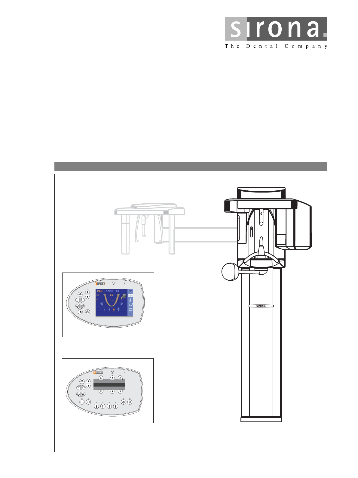
ORTHOPHOS XG 3D
ORTHOPHOS XG 5 / 3 / 3 PPE
sЙклбзе=OSKM
ready
/ XG
Plus
Page 2

About the Service Manual:
NOTE
i
NOTE
i
• This Service Manual is valid for the following unit versions:
– ORTHOPHOS XG 3D
– ORTHOPHOS XG
– ORTHOPHOS XG 5 DS / Ceph
– ORTHOPHOS PlusDS/PlusDSCeph / PPE*
– ORTHOPHOS XG 5 / Ceph
– ORTHOPHOS XG 3
These system versions differ regarding the equipment offered by their user interfaces and their possible configuration levels (see page 1-4).
Board DX41 is no longer installed in units with hardware version BA or higher (as of November 2006).
In addition, you also require:
• Spare parts list: Order No. 59 38 423
– ORTHOPHOS XG 3D
ORTHOPHOS XG 5 (DS) / Ceph,
ORTHOPHOS XG 3 (DS)
ready
Plus
DS / Ceph
ready
/ Ceph
/ Ceph, ORTHOPHOS XG
Plus
DS / Ceph,
• Wiring diagrams: Order No. 59 38 332
– ORTHOPHOS XG
Plus
DS / Ceph, ORTHOPHOS XG 5 (DS) / Ceph,
ORTHOPHOS XG 3 (DS): Bestell-Nr. 59 38 332
– ORTHOPHOS XG 3D
ready
/ Ceph: Bestell-Nr. 63 03 494
• Installation Instructions
– ORTHOPHOS XG
Plus
DS / Ceph, ORTHOPHOS XG 3D
– ORTHOPHOS XG 5 (DS) / Ceph: Order No. 60 04 902
– ORTHOPHOS XG 3 (DS): Order No. 60 51 416
• Tools
– Screwdriver, medium sized
– Torx offset screwdrivers TX10, TX20, TX25
– Open-end wrench, 13 mm A/F
– Socket wrench, 13 mm A/F
– Side cutters
– Spirit level
• Auxiliary devices
– Digital multimeter, Accuracy Class 1
– Mult-O-Meter 512L
– Soldering tool for repairing cables
– Cable ties
– Teflon tape
– Loctite
ready
/ Ceph: Order No. 59 87 651
*PPE = pay per exposure (optional)
Page 3
General information/Software update 1
Messages
Troubleshooting
Adjustment
2
3
4
Service routines 5
Repair
Maintenance
6
7
Page 4

Page 5

Contents
1 General information ..................................................................... 1-5
1.1 Safety .................................................................................. 1-5
1.2 Device classes XG
1.3 Operation notes ................................................................... 1-8
1.4 Demo mode – Operation without radiation release ........... 1-11
1.5 Demo mode – Repacking andtransport ............................ 1-13
1.6 List of software versions .................................................... 1-14
1.7 Software update ................................................................ 1-27
1.8 Opening the "Details" ........................................................ 1-37
1.9 Configuring X-ray components via the SIDEXIS Manager 1-39
1.10 The most important modules and components ................. 1-45
1.11 Cabling overview ............................................................... 1-50
1.12 Illustrations of boards ........................................................ 1-54
1.13 Remove covers ................................................................. 1-66
Plus
/ 3D
ready
and XG 5 / 3 / 3 PPE ....... 1-6
2 Messages .................................................................................... 2-3
2.1 Help messages ................................................................... 2-4
2.2 System messages ............................................................... 2-6
2.3 Status displays .................................................................... 2-6
2.4 Error messages ................................................................... 2-6
2.5 List of error messages ......................................................... 2-9
2.6 List of available service routines ....................................... 2-59
3 Troubleshooting .......................................................................... 3-3
3.1 Error logging memory .......................................................... 3-4
3.2 Check the CAN bus ............................................................. 3-6
3.3 Checking the boards ......................................................... 3-12
3.4 Checking the motors ......................................................... 3-15
3.5 Checking the light barriers ................................................ 3-16
3.6 Device leakage current too high ........................................ 3-17
3.7 Checking the cables .......................................................... 3-18
3.8 Error analysis of X-RAY control signal path:
up to unit hardware version AG
(with board DX41) ............................................................. 3-19
3.9 Error analysis of X-RAY control signal path:
unit HW version BA or higher
(without board DX41) ........................................................ 3-23
3.10 Checking data paths / Generating test images ................. 3-26
59 38 399 D3352
D3352.076.01.26.02 09.2016
V
Page 6

Contents
4 Adjustment ................................................................................... 4-3
4.1 Important information concerning adjustment ...................... 4-3
4.2 Diaphragm/system adjustment menu .................................. 4-5
4.3 Adjusting the panoramic X-ray unit ...................................... 4-9
4.4 Checking and adjusting the touchscreen
(only for XG
4.5 Adjusting the cephalometer
(XG
Plus
4.6 TSA sensor adjustment
(only for XG
4.7 Resetting the adjustment
(XG
Plus
/ 3D
/ 3D
Plus
ready
Plus
ready
ready
/ 3D
) .................................................. 4-55
/ XG 5, if ceph present) .......................... 4-58
with full version) ..................................... 4-109
/ 5 / 3 / 3 PPE) ...................................... 4-117
5 Service routines ......................................................................... 5-11
5.1 Selecting the Service menu ............................................... 5-12
5.2 Selecting a service routine ................................................. 5-17
5.3 Service routines with SIDEXIS .......................................... 5-20
5.4 Service routine S001 ......................................................... 5-23
5.5 Service routine S002 ......................................................... 5-25
5.6 Service routine S005 ......................................................... 5-30
5.7 Service routine S007 ......................................................... 5-44
5.8 Service routine S008 ......................................................... 5-53
5.9 Service routine S009 ......................................................... 5-61
5.10 Service routine S012 ......................................................... 5-64
5.11 Service routine S014 ......................................................... 5-74
5.12 Service routine S015 ......................................................... 5-81
5.13 Service routine S017 ......................................................... 5-84
5.14 Service routine S018 ....................................................... 5-121
5.15 Service routine S020 (not for XG 3 / 3 PPE) ................... 5-139
5.16 Service routine S021 (not for XG 3 / 3 PPE) ................... 5-143
5.17 Service routine S032 ....................................................... 5-148
5.18 Service routine S033 (not for XG 3 / 3 PPE) ................... 5-152
5.19 Service routine S034 ....................................................... 5-156
5.20 Service routine S037 ....................................................... 5-173
59 38 399 D3352
VI D3352.076.01.26.02 09.2016
Page 7

Contents
6 Repair .......................................................................................... 6-5
6.1 Safety check ........................................................................ 6-6
6.2 Replacing the height adjustment motor (M1_4)/spindle ...... 6-7
6.3 Replacing the ring motor (M1_3) ....................................... 6-19
6.4 Replacing the PAN actuators (M1_1/2) ............................. 6-22
6.5 Replace headrest .............................................................. 6-24
6.6 Easypad (XG
Plus
Or the Multipad for XG5 / 3 / 3 PPE) ................................. 6-26
6.7 Replacing the control panel ............................................... 6-29
6.8 Replacing/adjusting the FH light localizer (PAN) .............. 6-31
6.9 Replacing/adjusting the MS light localizer
laser module (PAN) ........................................................... 6-33
6.10 Replacing/adjusting the FH light localizer (Ceph) ............. 6-35
6.11 Removing the light localizers from the ring
(for XG
Plus
and XG 5, if present) ....................................... 6-37
6.12 Replacing the bite block holder ......................................... 6-38
6.13 Replacing the motor-driven diaphragm
(for XG
Plus
/ 3D
6.14 Replacing the fixed diagram (for XG 3 / 3 PPE) ................ 6-45
6.15 Replacing the X-ray tube assembly .................................. 6-48
6.16 Replacing the fan (tube assembly 1.0) .............................. 6-53
6.17 Replacing the fan (tube assembly 2.0) .............................. 6-54
6.18 Replacing the PAN (TSA) sensor holder ........................... 6-56
6.19 Replacing the ceph sensor holder ..................................... 6-60
6.20 Replace sensor ................................................................. 6-61
6.21 Replacing the light barriers ............................................... 6-62
6.22 Replacing circuit boards .................................................... 6-73
6.23 Replacing cables ............................................................. 6-101
ready
/ 3D
ready
) or
/ XG 5) .............................................. 6-41
59 38 399 D3352
D3352.076.01.26.02 09.2016
VII
Page 8

Contents
7 Maintenance ................................................................................ 7-3
7.1 Checking the height adjustment .......................................... 7-4
7.2 Checking the forehead and temple supports ....................... 7-6
7.3 Testing the rotating unit for smooth running ........................ 7-7
7.4 Checking the sensor holder (pan and ceph) ........................ 7-8
7.5 Checking the bite block holder ........................................... 7-10
7.6 Checking the light localizers .............................................. 7-11
7.7 Checking the X-ray images ................................................ 7-13
7.8 Checking the tube data ...................................................... 7-14
7.9 Checking the diaphragm .................................................... 7-20
7.10 Checking the cables for damage ....................................... 7-38
7.11 Checking the idling rollers .................................................. 7-39
7.12 Checking the grounding straps .......................................... 7-40
7.13 Checking the cable shields ................................................ 7-41
7.14 Checking the protective ground wires ................................ 7-42
7.15 Checking the unit leakage current ..................................... 7-46
59 38 399 D3352
VIII D3352.076.01.26.02 09.2016
Page 9

ORTHOPHOS XG
1General information
Page 10

Tab 1
Contents
1.1 Safety ......................................................................1 – 5
1.2 Device classes XG
Plus
XG 5 / 3 / 3 PPE......................................................1 – 6
1.2.1 Overview of the ORTHOPHOS XG
system classes and versions1 – 7
1.3 Operation notes.......................................................1 – 8
1.4 Demo mode – Operation without radiation release1 – 11
1.4.1 Switching the demo mode ON............................ 1 – 12
1.4.2 Switching the demo mode OFF.......................... 1 – 12
1.5 Demo mode – Repacking and transport ...............1 – 13
1.6 List of software versions........................................1 – 14
1.6.1 ORTHOPHOS XG 3 PPE ................................... 1 – 14
1.6.2 ORTHOPHOS XG 3 ........................................... 1 – 17
1.6.3 ORTHOPHOS XG 5 / Ceph ............................... 1 – 20
1.6.4 ORTHOPHOS XG
1.6.5 ORTHOPHOS XG 3D
ready
/ 3D
Plus
/ Ceph............................. 1 – 23
ready
and
/Ceph ....................... 1 – 26
1.7 Software update .................................................... 1 – 27
1.7.1 Important information on the software update.... 1 – 27
1.7.2 Performing a software update ............................ 1 – 29
1.7.3 Software update of ORTHOPHOS XG 5 to
V02.30 or higher ................................................. 1 – 34
1.7.4 Software update ORTHOPHOS XG
from version V02.20 to V02.30 or higher............ 1 – 35
1.7.5 Software update of ORTHOPHOS XG
version V02.22 to V02.30 or higher.................... 1 – 36
Plus
Plus
from
1.8 Opening the "Details" ............................................1 – 37
1.9 Configuring X-ray components via the
SIDEXIS Manager.................................................1 – 39
1.9.1 Setting up the X-ray component......................... 1 – 39
1.9.2 Selecting an X-ray component ........................... 1 – 40
1.9.3 Approval of the X-ray component....................... 1 – 43
1.9.4 Deleting the X-ray component............................ 1 – 44
1.10 The most important modules and components .....1 – 45
1.10.1 Slide ................................................................... 1 – 46
1.10.2 Stand .................................................................. 1 – 48
1.10.3 Cephalometer
(arm mounted on left side and on right side) ...... 1 – 49
1.10.4 Remote control ................................................... 1 – 49
1.11 Cabling overview................................................... 1 – 50
59 38 399 D3352
1 – 2 D3352.076.01.26.02 09.2016
Page 11

Tab 1
1.12 Illustrations of boards ............................................1 – 54
1.12.1 Boards in the slide.............................................. 1 – 54
1.12.2 Boards in the stand ............................................ 1 – 62
1.12.3 Boards in the cephalometer
(arm mounted on left side and on right side)...... 1 – 63
1.12.4 Boards in the remote control .............................. 1 – 64
1.13 Remove covers .....................................................1 – 66
59 38 399 D3352
D3352.076.01.26.02 09.2016
1 – 3
Page 12

Tab 1
59 38 399 D3352
1 – 4 D3352.076.01.26.02 09.2016
Page 13
1.1
Tab 1 1.1 Safety
CAUTION
WARNING
DANGER
1 General information
1.1 Safety
Repair work is only to be performed by trained dealers / service engineers who are authorized by Sirona. The Service Manual is provided
purely for these persons.
It is essential that you comply with the warning and safety information contained in this Service Manual.
All such information is highlighted by one of three signal words, i.e. WARNING, CAUTION or DANGER.
Nonobservance may result in minor physical injuries or material damage and
malfunctions.
Nonobservance may lead to serious physical injury or death.
Immediate danger to life and limb. Threat of serious physical injury or
death.
1.1
bеЦдблЬ
59 38 399 D3352
D3352.076.01.26.02 09.2016
1 – 5
Page 14
1.2 Device classes XG
NOTE
i
NOTE
i
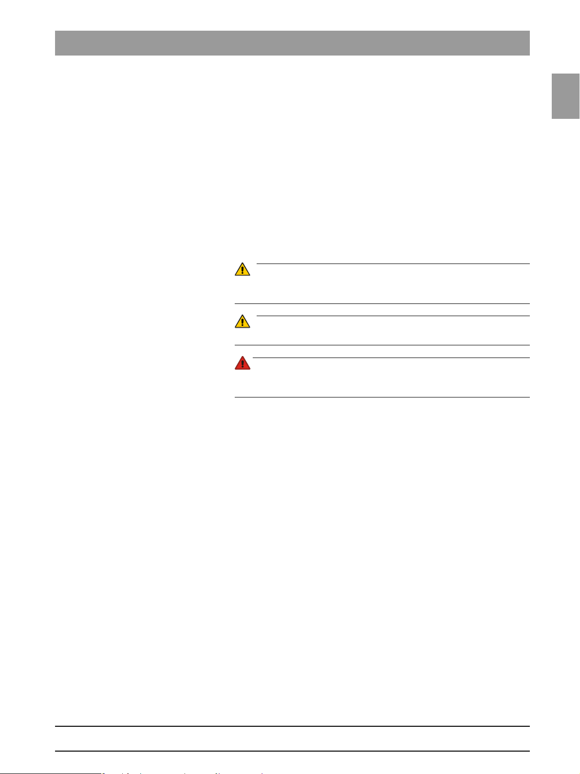
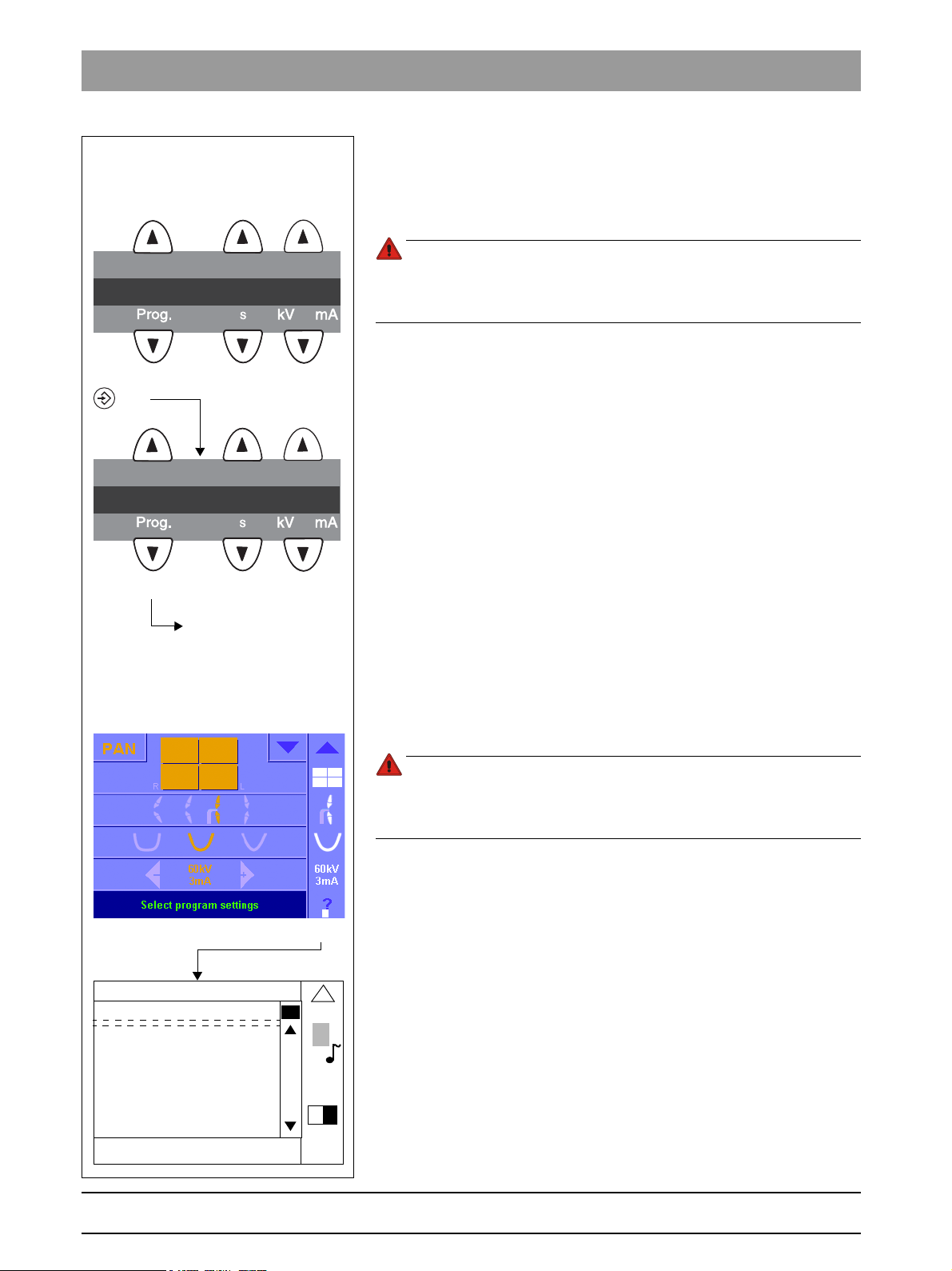
Comfort class with Easypad
(XG
Plus
/ 3D
ready
)
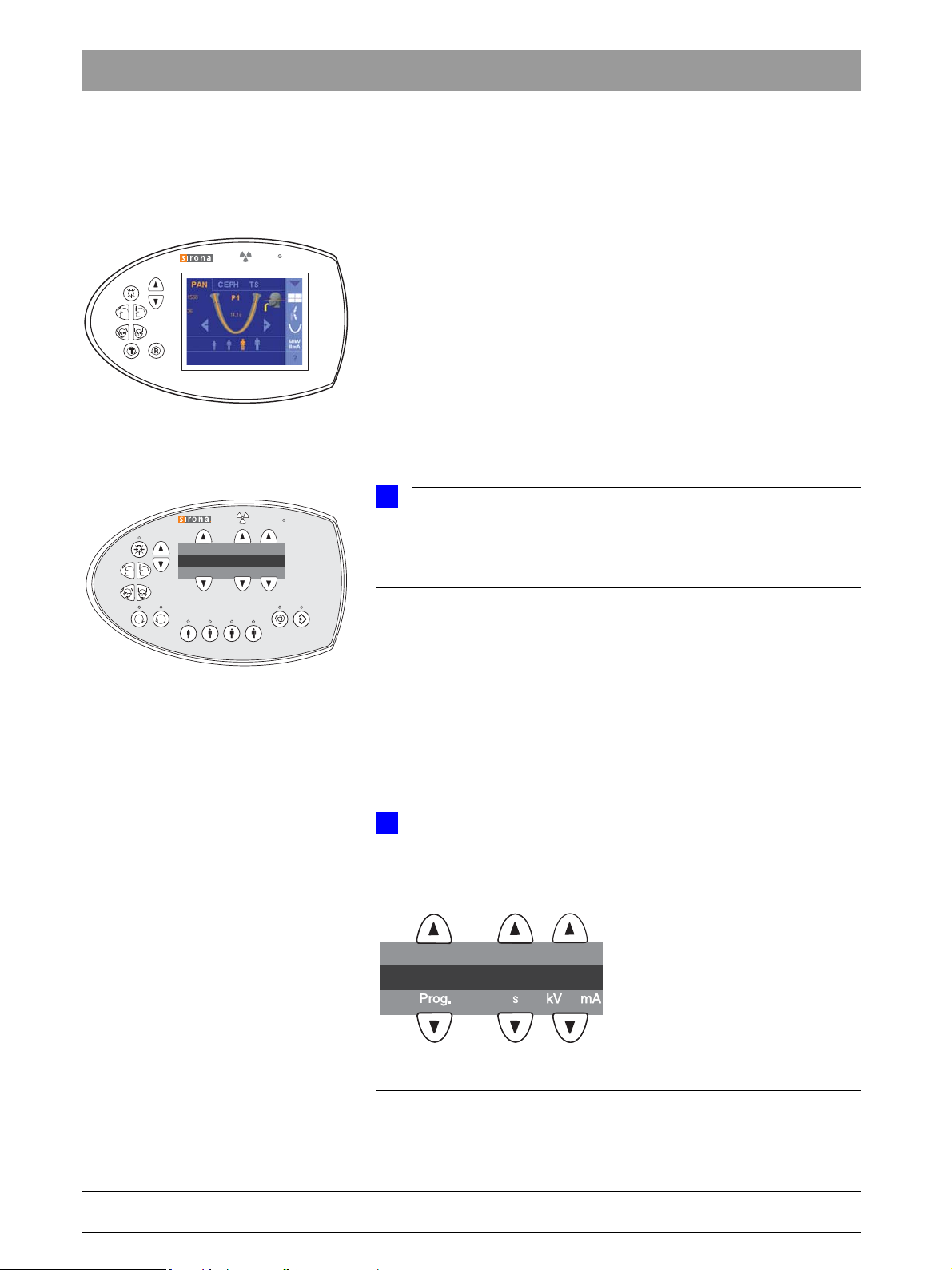
Basic class with Multipad
(XG 5 / 3 / 3 PPE)
T
R
Prog.
S
kV
mA
123
S005_______1____
Plus
/ 3D
ready
and XG 5 / 3 / 3 PPE Tab 1
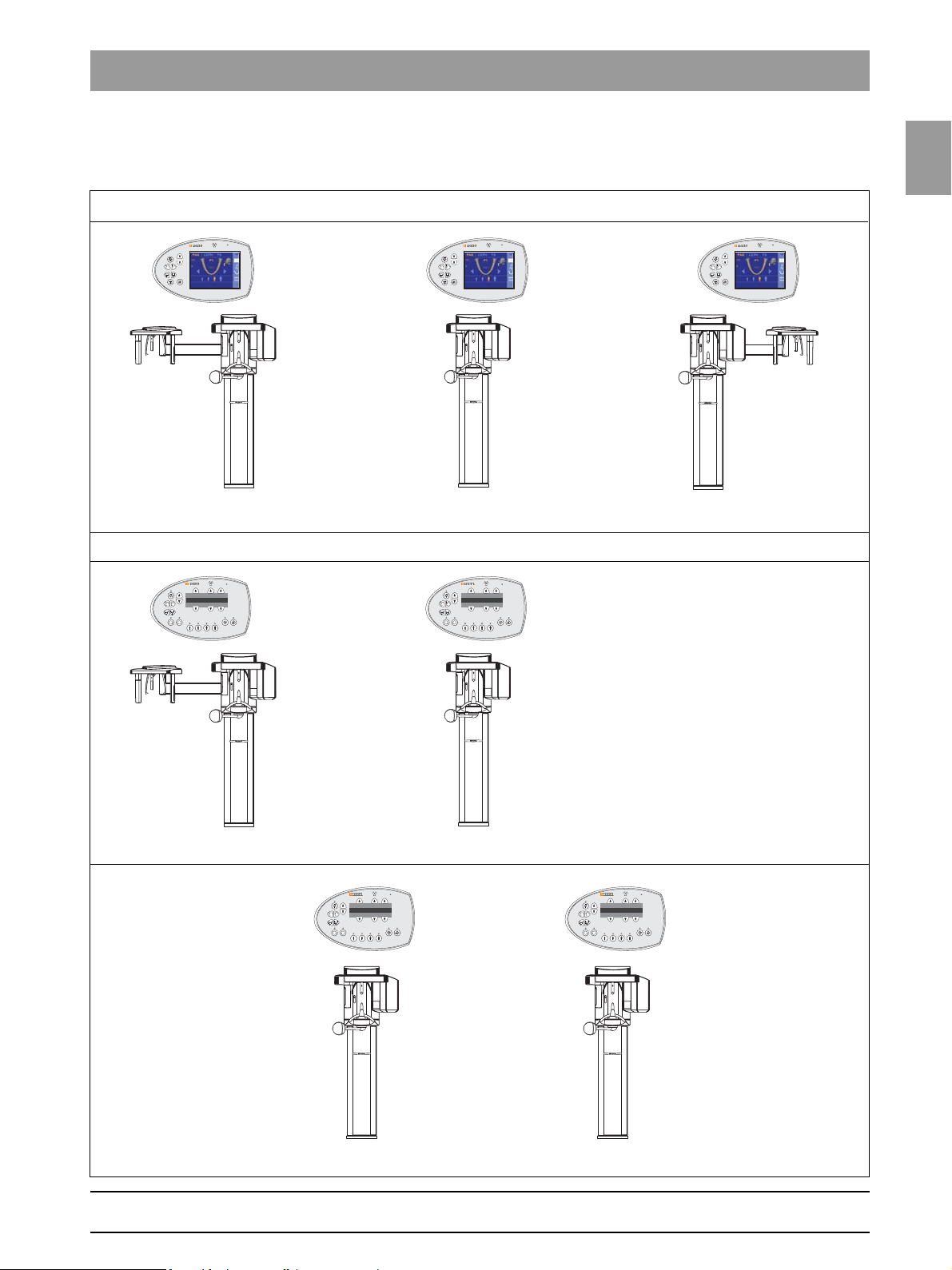
1.2
Device classes XG
Plus
/ 3D
ready
and XG 5 / 3 / 3
PPE
The XG
to their user interface. While the ORTHOPHOS XG (XG
class features a control panel with a color touchscreen (Easypad), the basic
class (XG5/3/3 PPE) is equipped with a simpler control panel with a single-line display (Multipad).
Due to their different control panels, the operating procedures for these two
system classes also vary.
All ORTHOPHOS XG units are digital systems.
The ORTHOPHOS XG
operation with a cephalometer (ceph). The cephalometer for the XG
3D
left or the right side. Only the cephalometer version with the arm mounted on
the left side is offered for the XG 5 system version. Operation of the XG 3/3
PPE system version is not possible with a cephalometer.
The version with the "left-handed arm" is essentially described and illustrated
in this service manual. The installation/removal procedure for the "right-handed arm" version must be performed with laterally reversed orientation where it
is not described separately.
Plus
ready
unit version is also available with the ceph arm mounted either on the
/ 3D
ready
and XG 5 / 3 / 3 PPE system versions differ with regard
Plus
/ 3D
ready
and XG 5 unit versions are suitable for
Plus
/ 3D
ready
) comfort
Plus
/
Remote control operation is possible in all system versions.
The comfort unit class (XG
However, the basic unit class (XG 5/3/3 PPE) is available only in a basic version.
Plus
The XG
This Service Manual describes both system classes in the highest possible
configuration.
For more information on the different installation versions, please refer to the
Installation Instructions.
The empty digits in the single-line display of the Multipad are marked
with underscores in this Manual. They have been added to enhance clarity
and are not present on the real Multipad.
system class optionally includes TSA operation.
Plus
/ 3D
ready
) comes in a basic and a full version.
1 – 6 D3352.076.01.26.02 09.2016
59 38 399 D3352
Page 15
1.2
Tab 1 1.2 Device classes XG
T
R
Prog.Prog.
S
kV
mA
T
R
Prog.
S
kV
mA
T
R
Prog.
S
kV
mA
ORTHOPHOS XG
Plus
/ 3D
ready
with ceph arm on right sidewith ceph arm on left side
Comfort class (Easypad, basic or full version, TSA option (not for XG 3D
ready
) , remote control option)
ORTHOPHOS XG 5with ceph arm on left side
ORTHOPHOS XG 3
Basic class (Multipad, basic equipment, remote release optional)
T
R
Prog.Prog.
S
kV
mA
ORTHOPHOS XG 3 PPE
1.2.1 Overview of the ORTHOPHOS XG system
classes and versions
Plus
/ 3D
ready
and XG 5 / 3 / 3 PPE
1.2
bеЦдблЬ
59 38 399 D3352
D3352.076.01.26.02 09.2016
1 – 7
Page 16
1.3 Operation notes Tab 1
1.3
Nominal line voltage The ORTHOPHOS XG X-ray unit can be operated in the following
Nominal line voltage ranges:
200 V - 240 V
50/60 Hz
The permissible line voltage fluctuation at:
200–240 V: ±10%
The internal line impedance must not exceed max. 0.8 Ω.
Operation notes
Fixed connection
Fixed connection
DANGER
Perilous shock hazard!
Fixed connection!
Installing a mains plug instead of the specified fixed connection infringes
international medical regulatory actions and is prohibited. In case of error, this puts patients, users, and other parties seriously at risk.
Remote control The system can be equipped with...
a 1–3m coiled cable with release button inside the treatment room or ...
a remote control with or without coiled cable located outside the X-ray
room (see installation instructions).
Warm-up time After it is switched ON, the system requires a warm-up time of approx. 1 min.
Self-adjustment routine At the same time, a mechanical and electronic self-adjustment routine is exe-
cuted. If a button is pressed during the self-adjustment routine, an error message is displayed on the Multipad (XG5 / 3 / 3 PPE) or on the Easypad (XG
ready
/ 3D
Cooling period The cooling period between two exposures is maintained by an automatic
exposure blocking function according to the pulse/pause ratio. A countdown
of the waiting time is displayed on the Multipad (XG5 / 3 / 3 PPE) or the Easypad (XGXG
Turn-off time The turn-off time must amount to at least 60 s.
Demo units If the X-ray unit is to be presented as a demo unit at trade fairs or exhibitions,
it must be ensured that radiation release is blocked (see "Demo mode – Operation without radiation release" on page 1-11).
Software version The overall system software version is determined by the software statuses of
the EEPROMs on the boards (see "List of software versions" on page 1-14).
Wireless phone interference with medical electrical equipment
Disposal The X-ray tube assembly contains a tube with potential implosion hazard, a
To ensure safe operation of medical electrical equipment, the use of mobile
wireless phones in practice or hospital environments is prohibited.
small amount of beryllium, a lead lining as well as mineral oil.
).
Plus
/ 3D
ready
).
Plus
59 38 399 D3352
1 – 8 D3352.076.01.26.02 09.2016
Page 17

1.3
Tab 1 1.3 Operation notes
CAUTION
WARNING
Error messages Error messages are displayed on the display of the Multipad (XG5/3/3 PPE)
or on the touchscreen of the Easypad (XG
Help messages in case exposure readiness cannot be attained
If you have to remove covers from the
unit.
Secondary diaphragm Do not manually move or otherwise exert force on the secondary diaphragm
Measurements Always switch the unit OFF before connecting a measuring instrument.
Help messages are displayed on the display of the Multipad (XG5/3/3 PPE)
or on the touchscreen of the Easypad (XG
Proceed according to section "1.13 Remove covers".
When removing covers, always remember that direct sunlight or bright room
lighting can cause system malfunctions due to activated light barriers.
I.e.: avoid direct sunlight and bright room lighting above the unit!
When attaching the covers: Be sure to screw the sheet metal cover back on.
For reasons of electromagnetic compatibility, be sure to fasten all screws.
Reattach the covers.
(e.g. when removing it from its packaging).
Select the correct current/voltage type and adjust the measuring range to
match the expected readings.
Perform continuity tests only on units which are switched off.
Plus
Plus
/ 3D
/ 3D
ready
ready
).
).
1.3
bеЦдблЬ
If several exposures with radiation must be taken to check a measurement,
make sure that the prescribed cool-down intervals are observed. They are
maintained by an automatic exposure blocking function (see Operating
Instructions).
The pulse/pause ratio is 1:10, i.e. a 10-second pause is maintained for each
second of radiation emission. The pulse/pause ratio is automatically maintained (automatic exposure blocking).
A pulse/pause ratio of 1:20 is better for the X-ray tube.
It is essential that you observe the radiation protection regulations applicable in your country prior to radiation release.
The test rotations triggered by pressing the T key on the Easypad and then
the release button are executed without radiation.
59 38 399 D3352
D3352.076.01.26.02 09.2016
1 – 9
Page 18
1.3 Operation notes Tab 1
Replacing parts Switch off the unit before replacing parts.
When replacing parts in the vicinity of the power connection, the power
switch, board DX32, or the X-ray tube assembly, disconnect the unit from the
distribution box of the building installation.
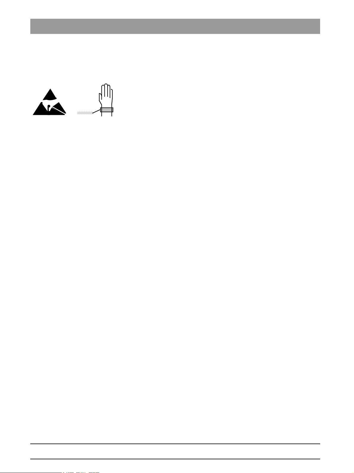
Please always wear an ESD wrist band to protect sensitive components on
printed circuit boards (ESD).
Always check the system and adjust it as required after replacing a board or
the X-ray tube assembly.
The article numbers for ordering spare parts can be found in the spare parts
list, Order No. 59 38 423. The diagrams contained in the spare parts list provide a useful guide when replacing parts.
Safety check A protective ground wire test and a leakage current test must be performed
prior to the installation or the hand-over of the unit as well as after repair work.
See sections "7.14 Checking the protective ground wires " and "7.15 Checking the unit leakage current ".
Functional check Following any form of service and maintenance work, a functional check must
be performed on the device.
Perform the following test steps:
1. Perform a restart of the unit:
– Turn the device off.
– Wait 1 minute.
– Switch the unit on.
– Wait until the self-test is finished.
2. Perform a test exposure using the needle phantom included in the scope
of supply.
59 38 399 D3352
1 – 10 D3352.076.01.26.02 09.2016
Page 19
1.4
Tab 1 1.4 Demo mode – Operation without radiation release
NOTE
i
A
B
3+4.
1.
2.
DX6 tube assembly 1.0
J6
S2
3+4.
DX6 tube assembly 2.0
J6
S2
1.4 Demo mode – Operation without radiation
release
1.4
bеЦдблЬ
59 38 399 D3352
D3352.076.01.26.02 09.2016
Starting with system SW version V02.28.02, the complete possible functionality of the system class is simulated, regardless of the current configuration.
1 – 11
Page 20
1.4 Demo mode – Operation without radiation release Tab 1
DANGER
DANGER
5.
Info menu for XG 5/3
65
Mac address : 010001200000
IP address : 192.168.15.19
Subnet mask : 155.155.255.0
Default gateway : 192.168.15.1
Net API version : 1
Net API revision : 14
Demo mode : ON
Tube exposures : 2217
Orthophos XG configuration
Info screen for XG
Plus
/ 3D
ready
123
P1______14.1__64_8
123
SYSTEM
Scroll through the list
until the demo mode is
displayed
2/2
1.4.1 Switching the demo mode ON
When operated in demo mode, the unit must not release any radiation. For
this reason, you must take the following safety measures:
Turn the device OFF.
PERILOUS SHOCK HAZARD! It is essential to switch the unit off and to
wait at least another minute before taking off the covers of the tube
assembly.
1. Remove the cover of the tube assembly.
2. Loosen the screws (A) and remove the cover plate (B).
3. Set the DIP switch S2 (DX6) to Position 2.
4. Pull the cable L5 (X-RAY) off from connector J6 (DX6).
Radiation release is now no longer possible.
5. Switch the unit ON and check the mode with the
info menu (XG 5 / 3 / 3 PPE) / the info screen (XG
Demo mode: ON means that: The demo mode is switched ON
(Radiation release is not possible)
Demo mode: OFF means: The demo mode is switched OFF
(Radiography, radiation is possible)
Switch the unit OFF again and reattach cover plate B and the tube assem-
bly covers by following the dismantling procedure in reverse order.
Plus
/ 3D
ready
).
1 – 12 D3352.076.01.26.02 09.2016
1.4.2 Switching the demo mode OFF
Turn the device OFF.
PERILOUS SHOCK HAZARD! It is essential to switch off the unit and to
wait at least another 1 minute before taking off the covers of the X-ray
tube assembly.
1. Remove the cover of the tube assembly.
2. Loosen the screws A and remove the cover plate B.
3. Set the DIP switch S2 (DX6) to Position 1.
4. Connect cable L5 (X-RAY) to connector J6 (DX6).
Radiation release is now once again possible.
5. Switch the unit ON and check the mode with the
info menu (XG 5 / 3 / 3 PPE) / the info screen (XG
Demo mode: ON means that: The demo mode is switched ON
(Radiation release is not possible)
Demo mode: OFF means: The demo mode is switched OFF
(Radiography, radiation is possible)
Switch the unit OFF again and reattach cover plate B and the tube assem-
bly covers by following the dismantling procedure in reverse order.
Plus
/ 3D
ready
).
59 38 399 D3352
Page 21
1.5
Tab 1 1.5 Demo mode – Repacking andtransport
NOTE
i
DANGER
1.
A
NOTE
i
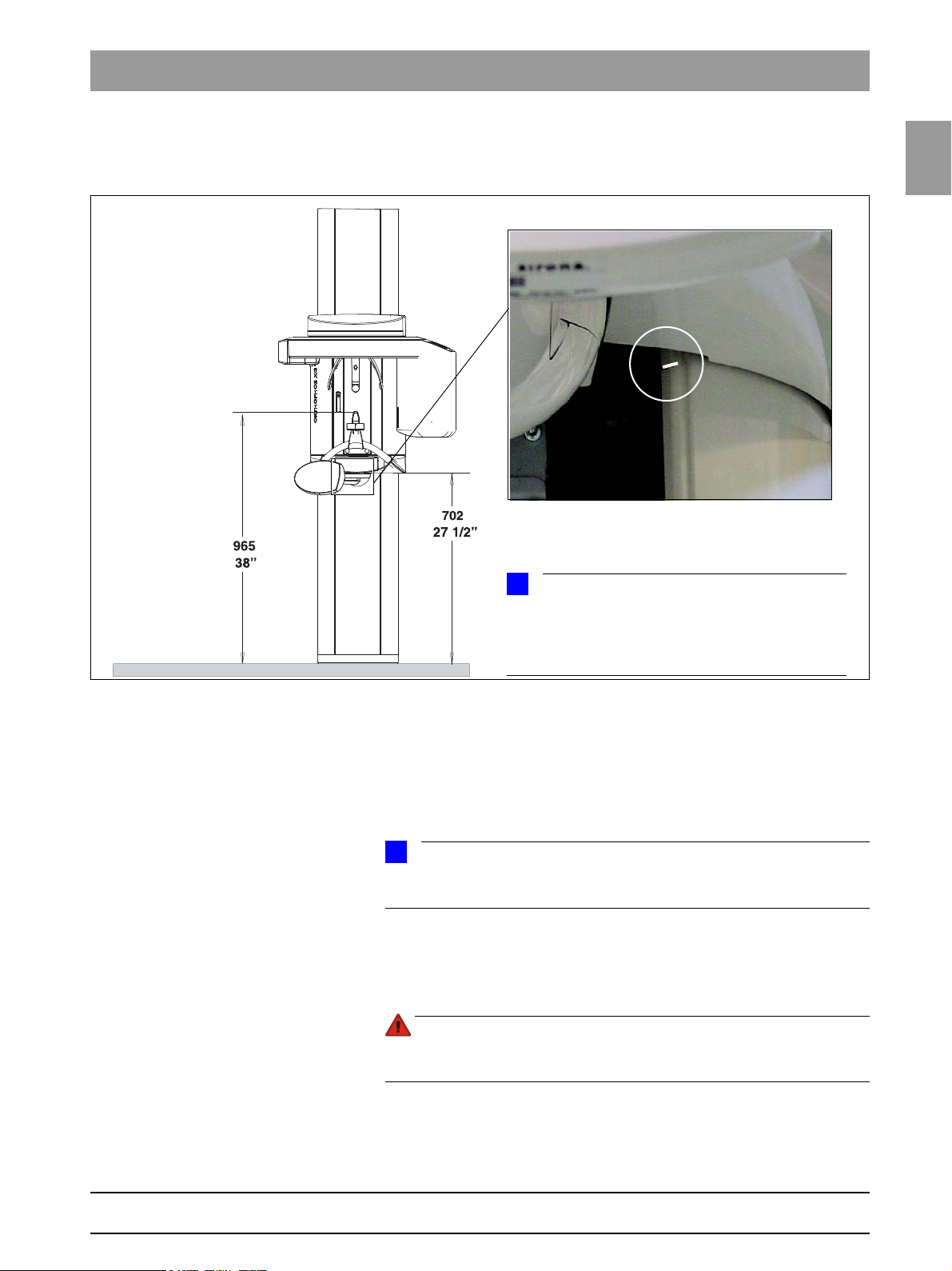
If the unit is installed with a floor stand, its height increases by 30mm. The bite block height value displayed on the Multipad (XG5/3/3 PPE) or Easypad
(XG
Plus
/ 3D
ready
) remains the same, however.
1.5 Demo mode –
Repacking andtransport
1.5
bеЦдблЬ
Panoramic X-ray unit Switch the panoramic X-ray unit ON and move it to its packing height by
pressing the UP/DOWN keys on the Multipad (XG5/3/3 PPE) or Easypad
Plus
(XG
– Bite block height = 965 mm (displayed as height on Multipad (XG5/3/3
PPE) or
Cephalometer Start service routine S034, test step 6.
Easypad (XG
– Bottom edge of slide cover = 702 mm
The bottom edge of the slide cover must be at the same height as the markings A in the column.
Move the cephalometer to the packing position
(see page 5-165).
Turn the device OFF.
PERILOUS SHOCK HAZARD! Prior to disconnecting the line voltage,
you must switch off the power connection and wait 1 minute?.
Unplug any connections between the external units and the DX41 board
or interface board, and disconnect the unit from the power supply.
For information on packing the units and on the packing condition, see the
relevant installation instructions.
/ 3D
ready
).
Plus
/ 3D
ready
) displayed as height)
59 38 399 D3352
D3352.076.01.26.02 09.2016
1 – 13
Page 22
1.6 List of software versions Tab 1
NOTE
i
1.6
List of software versions
Any software combinations other than those listed here are
not allowed. If the software version of any particular module does not match
the overall software version, the overall software version will be
marked with an asterisk on the info screen (e.g. 02.20*).
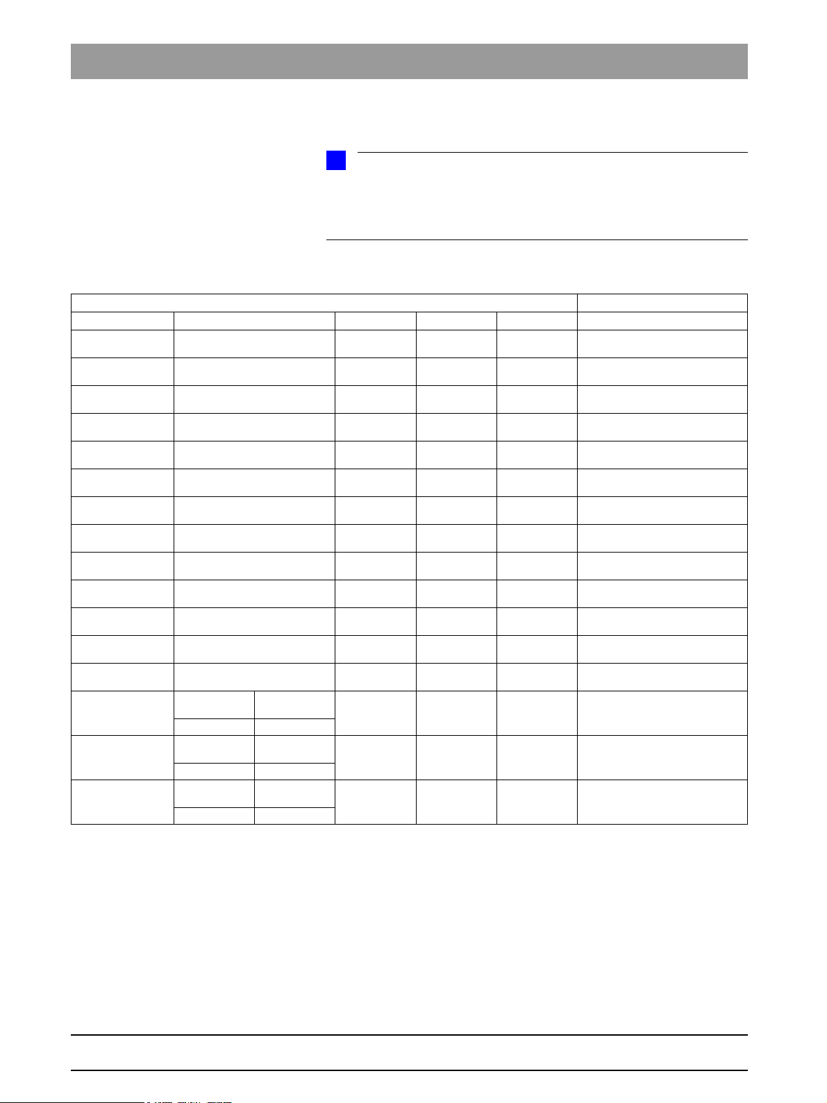
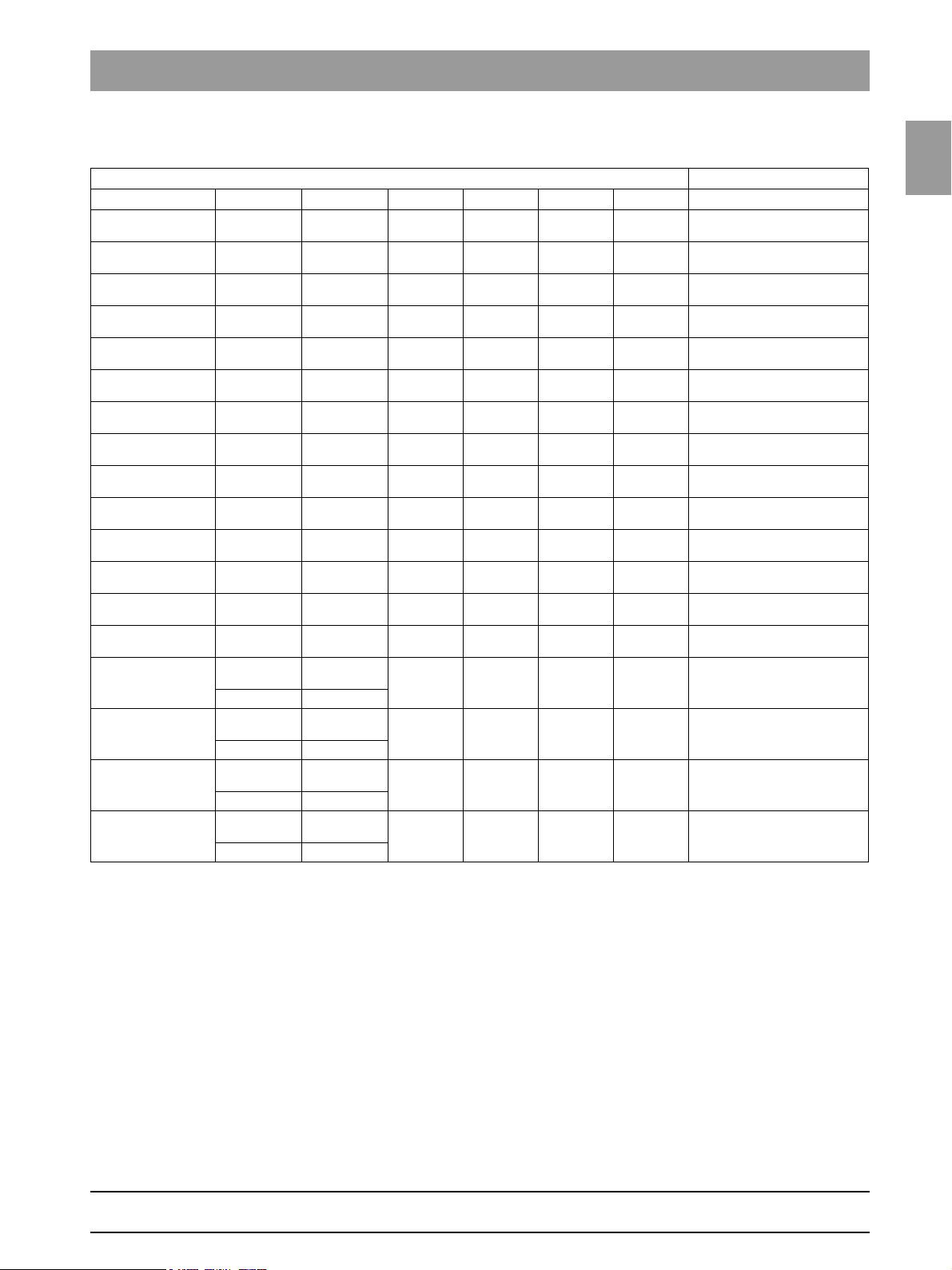
1.6.1 ORTHOPHOS XG 3 PPE
Panoramic unit
Board DX6 DX71 DX11 DX81
Overall software
V 02.28
Overall software
V 02.28.2
Overall software
V 02.30
Overall software
V 02.31
Overall software
V 02.32
Overall software
V 02.35
Overall software
V 02.40
Overall software
V 02.41
Overall software
V 02.41.01
Overall software
V 02.51.01
Overall software
V 02.51.02
Overall software
V 02.51.03
Overall software
V 02.54.00
Overall software
V 02.54.01
Overall software
V 02.58.00
Overall software
V 02.58.02
Tube assem-
bly 1.0
03.06.03 04.07.01
Tube assem-
bly 1.0
03.08.00 04.09.07
Tube assem-
bly 1.0
03.08.00 04.10.06
02.60 02.33 02.40 02.33
02.60 02.33 02.40.01 02.33
02.60 02.34 02.42 02.33
02.60 02.34 02.42 02.33
02.60 02.34 02.43 02.33
02.61 02.35 02.45 02.33
02.61 02.35 02.47 02.33
02.62 02.36 02.48 02.33
02.63 02.37 02.48 02.33
03.05.00 02.54.00 02.51.01 02.33
03.06.00 02.54.00 02.51.02 02.33
03.06.00 02.54.00 02.51.03 02.33
03.06.01 02.54.03 02.54.00 02.33
Tube assem-
bly 2.0
Tube assem-
bly 2.0
Tube assem-
bly 2.0
02.54.03 02.54.01 02.33
02.55.02 02.58.00 02.33
02.55.02 02.59.07 02.33
* Exception: SIDEXIS version V02.00
Note
compatible with
SIDEXIS versions V01.61
compatible with
SIDEXIS versions V01.61
compatible with
SIDEXIS versions V01.61
compatible with
SIDEXIS versions V01.61
compatible with
SIDEXIS versions V01.61
compatible with
SIDEXIS versions V01.61
compatible with
SIDEXIS versions V01.61
compatible with
SIDEXIS versions V01.61
compatible with
SIDEXIS versions V01.61
compatible with
SIDEXIS versions V01.61
compatible with
SIDEXIS Version V01.61*
compatible with
SIDEXIS Version V01.61*
compatible with
SIDEXIS Version V01.61*
compatible with
SIDEXIS Version V01.61*
compatible with
SIDEXIS Version V01.61 – V2.5*
compatible with
SIDEXIS Version V01.61 – V2.5*
59 38 399 D3352
1 – 14 D3352.076.01.26.02 09.2016
Page 23
1.6
Tab 1 1.6 List of software versions
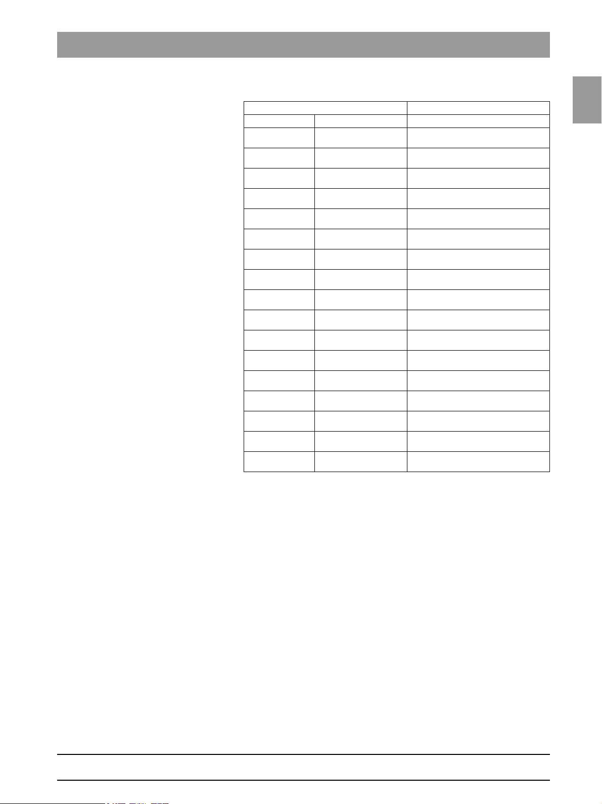
Remote control
Board DX42
Overall software
V 02.28
Overall software
V 02.28.2
Overall software
V 02.30
Overall software
V 02.31
Overall software
V 02.32
Overall software
V 02.35
Overall software
V 02.40
Overall software
V 02.41
Overall software
V 02.41.01
Overall software
V 02.51.01
Overall software
V 02.51.01
Overall software
V 02.51.02
Overall software
V 02.51.03
Overall software
V 02.54.00
Overall software
V 02.54.01
Overall software
V 02.58.00
Overall software
V 02.58.02
02.30
02.30
02.31
02.31
02.31
02.50
02.52
02.52
02.52
02.54.00
02.54.00
02.54.00
02.54.00
02.56.02
02.56.02
02.58.02
02.58.02
Note
1.6
bеЦдблЬ
59 38 399 D3352
D3352.076.01.26.02 09.2016
1 – 15
Page 24
1.6 List of software versions Tab 1
NOTE
i
Sidexis XG
V 01.53
V 01.54
V 01.55
V 01.61
V 02.00
V 2.2
V 2.3
V 2.4
V 2.5
V 2.5.3
V 2.5.6
Note Database
requires ORTHOPHOS XG 3 PPE
overall software version V02.28.2 or higher
requires ORTHOPHOS XG 3 PPE
overall software version V02.28.2 or higher
requires ORTHOPHOS XG 3 PPE
overall software version V02.28.2 or higher
requires ORTHOPHOS XG 3 PPE
overall software version V02.28.2 or higher
requires ORTHOPHOS XG 3 PPE
overall software version V02.28.2 or higher
Exception: Overall software V2.51.2 is not
compatible with Sidexis XG version V02.00.
requires ORTHOPHOS XG 3 PPE
overall software version V02.28.2 or higher
requires ORTHOPHOS XG 3 PPE
overall software version V02.28.2 or higher
requires ORTHOPHOS XG 3 PPE
overall software version V02.28.2 or higher
requires ORTHOPHOS XG 3 PPE
overall software version V02.28.2 or higher
requires ORTHOPHOS XG 3 PPE
overall software version V02.28.2 or higher
requires ORTHOPHOS XG 3 PPE
overall software version V02.28.2 or higher
Old database
New database
59 38 399 D3352
1 – 16 D3352.076.01.26.02 09.2016
Page 25
1.6
Tab 1 1.6 List of software versions
1.6.2 ORTHOPHOS XG 3
Panoramic unit
Board DX6 DX71 DX11 DX41 DX81
Overall software
V 02.25
Overall software
V 02.27
Overall software
V 02.28
Overall software
V 02.28.2
Overall software
V 02.30
Overall software
V 02.31
Overall software
V 02.32
Overall software
V 02.35
Overall software
V 02.41
Overall software
V 02.41.01
Overall software
V 02.51.01
Overall software
V 02.51.02
Overall software
V 02.51.03
Overall software
V 02.54
Overall software
V 02.54.01
Overall software
V 02.58.00
Overall software
V 02.58.01
Overall software
V 02.58.02
Tube assem-
bly 1.0
03.06.03 04.07.01
Tube assem-
bly 1.0
03.08.00 04.09.07
Tube assem-
bly 1.0
03.08.00 04.09.07
Tube assem-
bly 1.0
03.08.00 04.10.06
02.57 02.29 02.37 02.22 02.30
02.60 02.31 02.39 02.23 02.32
02.60 02.33 02.40 (02.23*) 02.33
02.60 02.33 02.40.01 (02.23*) 02.33
02.60 02.34 02.42 (02.23*) 02.33
02.60 02.34 02.42 (02.23*) 02.33
02.60 02.34 02.43 (02.23*) 02.33
02.61 02.35 02.45 (02.23*) 02.33
02.62 02.36 02.48 (02.23*) 02.33
02.63 02.37 02.48 (02.23*) 02.33
03.05.00 02.54.00 02.51.01 02.30.00 02.33
03.06.00 02.54.00 02.51.02 02.30.00 02.33
03.06.00 02.54.00 02.51.03 02.30.00 02.33
03.06.01 02.54.03 02.54.00 02.30.00 02.33
Tube assem-
bly 2.0
Tube assem-
bly 2.0
Tube assem-
bly 2.0
Tube assem-
bly 2.0
02.54.03 02.54.01 02.30.00 02.33
02.55.02 02.58.00 02.30.00 02.33
02.55.02 02.58.00 02.30.00 02.33
02.55.02 02.59.07 02.30.00 02.33
* Exception: SIDEXIS version V02.00
Note
compatible with
SIDEXIS versions V01.45
compatible with
SIDEXIS version V01.53
compatible with
SIDEXIS version V01.53
compatible with
SIDEXIS version V01.53
compatible with
SIDEXIS version V01.53
compatible with
SIDEXIS version V01.53
compatible with
SIDEXIS version V01.53
compatible with
SIDEXIS versions V01.61
compatible with
SIDEXIS versions V01.61
compatible with
SIDEXIS versions V01.61
compatible with
SIDEXIS versions V01.61
compatible with
SIDEXIS Version V01.61*
compatible with
SIDEXIS Version V01.61*
compatible with
SIDEXIS Version V01.61*
compatible with
SIDEXIS Version V01.61*
compatible with
SIDEXIS Version V01.61 –
V2.5*
compatible with
SIDEXIS Version V01.61 –
V2.5*
compatible with
SIDEXIS Version V01.61 –
V2.5*
1.6
bеЦдблЬ
59 38 399 D3352
D3352.076.01.26.02 09.2016
1 – 17
Page 26

1.6 List of software versions Tab 1
Remote control
Board DX42
Overall software
V 02.25
Overall software
V 02.27
Overall software
V 02.28
Overall software
V 02.28.2
Overall software
V 02.30
Overall software
V 02.31
Overall software
V 02.32
Overall software
V 02.35
Overall software
V 02.40
Overall software
V 02.41
Overall software
V 02.41.01
Overall software
V 02.51.01
Overall software
V 02.51.02
Overall software
V 02.51.03
Overall software
V 02.54.00
Overall software
V 02.54.01
Overall software
V 02.58.00
Overall software
V 02.58.01
Overall software
V 02.58.02
02.27
02.28
02.30
02.30
02.31
02.31
02.31
02.50
02.52
02.52
02.52
02.54.00
02.54.00
02.54.00
02.56.02
02.56.02
02.58.02
02.58.02
02.58.02
Note
59 38 399 D3352
1 – 18 D3352.076.01.26.02 09.2016
Page 27
1.6
Tab 1 1.6 List of software versions
NOTE
i
Sidexis XG
V 01.51
V 01.53
V 01.54
V 01.55
V 01.61
V 02.00
V 2.2
V 2.3
V 2.4
V 2.5
V 2.5.3
V 2.5.6
Note Database
requires ORTHOPHOS XG 3 overall software
version V02.25 or higher
requires ORTHOPHOS XG 3
overall software version V02.25 or higher
requires ORTHOPHOS XG 3
overall software version V02.25 or higher
requires ORTHOPHOS XG 3 PPE
overall software version V02.28.2 or higher
requires ORTHOPHOS XG 3 overall software
version V02.25 or higher
requires ORTHOPHOS XG 3
overall software version V02.25 or higher
Exception: Overall software V2.51.2 is not
compatible with Sidexis XG version V02.00.
requires ORTHOPHOS XG 3 overall software
version V02.25 or higher
requires ORTHOPHOS XG 3 overall software
version V02.28.2 or higher
requires ORTHOPHOS XG 3 overall software
version V02.28.2 or higher
requires ORTHOPHOS XG 3 overall software
version V02.28.2 or higher
requires ORTHOPHOS XG 3 overall software
version V02.28.2 or higher
requires ORTHOPHOS XG 3 PPE
overall software version V02.28.2 or higher
Old database
New database
1.6
bеЦдблЬ
* As of hardware version BA (from November 2006) new systems will be delivered without
board DX41 (see also page 1-44).
59 38 399 D3352
D3352.076.01.26.02 09.2016
1 – 19
Page 28
1.6 List of software versions Tab 1
1.6.3 ORTHOPHOS XG 5 / Ceph
Panoramic unit Cephalo-
Board DX6 DX71 DX11 DX41 DX61 DX81 DX91
Overall software
V 02.18.1
Overall software
V 02.20
Overall software
V 02.22
Overall software
V 02.25
Overall software
V 02.27
Overall software
V 02.28
Overall software
V 02.28.2
Overall software
V 02.30
Overall software
V 02.31
Overall software
V 02.32
Overall software
V 02.35
Overall software
V 02.40
Overall software
V 02.41
Overall software
V 02.41.01
Overall software
V 02.51.01
Overall software
V 02.51.02
Overall software
V 02.51.03
Overall software
V 02.54
Overall software
V 02.54.01
Overall software
V 02.58.00
Overall software
V 02.58.01
Overall software
V 02.58.02
02.45 02.23 02.31 02.19 02.20 02.25 02.32
02.56 02.28 02.33 02.22 02.26 02.29 02.34
02.56 02.28 02.35 02.22 02.30 02.29 02.38
02.57 02.29 02.37 02.22 02.30 02.30 02.40
02.60 02.31 02.39 02.23 02.33 02.32 02.42
02.60 02.33 02.40 (02.23*) 02.33 02.33 02.42
02.60 02.33 02.40.01 (02.23*) 02.34 02.33 02.43
02.60 02.34 02.42 (02.23*) 02.34 02.33 02.43
02.60 02.34 02.42 (02.23*) 02.34 02.33 02.44
02.60 02.34 02.43 (02.23*) 02.35 02.33 02.44
02.61 02.35 02.45 (02.23*) 02.35 02.33 02.44
02.61 02.35 02.47 (02.23*) 02.35 02.33 02.44
02.62 02.36 02.48 (02.23*) 02.35 02.33 02.44
02.63 02.37 02.48 (02.23*) 02.35 02.33 02.44
03.05.00 02.54.00 02.51.01 02.30.00 04.01.00 02.33 02.44.00
03.06.00 02.54.00 02.51.02 02.30.00 04.01.00 02.33 02.44.00
03.06.00 02.54.00 02.51.03 02.30.00 04.01.00 02.33 02.44.00
03.06.01 02.54.03 02.54.00 02.30.00 04.02.00 02.33 02.44.00
Tube
assem-
bly 1.0
03.06.03 04.07.01
Tube
assem-
bly 1.0
03.08.00 04.09.07
Tube
assem-
bly 1.0
03.08.00 04.09.07
Tube
assem-
bly 1.0
03.08.00 04.10.06
Tube
assem-
bly 2.0
Tube
assem-
bly 2.0
Tube
assem-
bly 2.0
Tube
assem-
bly 2.0
02.54.03 02.54.01 02.30.00 04.02.00 02.33 02.44.00
02.55.02 02.58.00 02.30.00 04.04.00 02.33 02.45.00
02.55.02 02.58.00 02.30.00 04.04.00 02.33 02.45.00
02.55.02 02.59.07 02.30.00 04.04.00 02.33 02.45.00
* Exception: SIDEXIS version V02.00
meter
Note
compatible with SIDEXIS versions up to and incl. V01.44
compatible with
SIDEXIS versions V01.45
compatible with
SIDEXIS versions V01.45
compatible with
SIDEXIS versions V01.45
compatible with
SIDEXIS version V01.53
compatible with
SIDEXIS version V01.53
compatible with
SIDEXIS version V01.53
compatible with
SIDEXIS version V01.53
compatible with
SIDEXIS version V01.53
compatible with
SIDEXIS version V01.53
compatible with
SIDEXIS version V01.53
compatible with
SIDEXIS versions V01.61
compatible with
SIDEXIS versions V01.61
compatible with
SIDEXIS versions V01.61
compatible with
SIDEXIS versions V01.61
compatible with
SIDEXIS Version V01.61*
compatible with
SIDEXIS Version V01.61*
compatible with
SIDEXIS Version V01.61*
compatible with
SIDEXIS Version V01.61*
compatible with
SIDEXIS Version V01.61 –
V2.5*
compatible with
SIDEXIS Version V01.61 –
V2.5*
compatible with
SIDEXIS Version V01.61 –
V2.5*
59 38 399 D3352
1 – 20 D3352.076.01.26.02 09.2016
Page 29
1.6
Tab 1 1.6 List of software versions
Remote control
Board DX42
Overall software
V 02.18.1
Overall software
V 02.20
Overall software
V 02.22
Overall software
V 02.25
Overall software
V 02.27
Overall software
V 02.28
Overall software
V 02.28.2
Overall software
V 02.30
Overall software
V 02.31
Overall software
V 02.32
Overall software
V 02.35
Overall software
V 02.40
Overall software
V 02.41
Overall software
V 02.41.01
Overall software
V 02.51.01
Overall software
V 02.51.02
Overall software
V 02.51.03
Overall software
V 02.54.00
Overall software
V 02.54.01
Overall software
V 02.58.00
Overall software
V 02.58.01
Overall software
V 02.58.02
02.22
02.27
02.27
02.27
02.28
02.30
02.30
02.31
02.31
02.31
02.50
02.52
02.52
02.52
02.54.00
02.54.00
02.54.00
02.56.02
02.56.02
02.58.02
02.58.02
02.58.02
Note
1.6
bеЦдблЬ
59 38 399 D3352
D3352.076.01.26.02 09.2016
1 – 21
Page 30
1.6 List of software versions Tab 1
NOTE
i
Sidexis XG
V 01.33 - V01.44
V 01.45
V 01.50
V 01.51
V 01.53
V 01.54
V 01.55
V 01.61
V 02.00
V 2.2
V 2.3
V 2.4
V 2.5
V 2.5.3
V 2.5.6
* As of hardware version BA (from November 2006) new systems will be delivered without
board DX41 (see also page 1-44).
Note Database
requires ORTHOPHOS XG 5 overall
software version < V02.20
requires ORTHOPHOS XG 5 overall
software version V02.20 or higher
requires ORTHOPHOS XG 5 overall
software version V02.20 or higher
requires ORTHOPHOS XG 5 overall
software version V02.20 or higher
requires ORTHOPHOS XG 5 overall
software version V02.20 or higher
requires ORTHOPHOS XG 5 overall
software version V02.20 or higher
requires ORTHOPHOS XG 5
overall software version V02.28.2 or
higher
requires ORTHOPHOS XG 5 overall
software version V02.20 or higher
requires ORTHOPHOS XG 5 overall
software version V02.20 or higher
Exception: Overall software V2.51.2 is
not compatible with Sidexis XG version
V02.00.
requires ORTHOPHOS XG 5 overall
software version V02.20 or higher
requires ORTHOPHOS XG 5 overall
software version V02.28.2 or higher
requires ORTHOPHOS XG 5
overall software version V02.28.2 or
higher
requires ORTHOPHOS XG 5
overall software version V02.28.2 or
higher
requires ORTHOPHOS XG 5
overall software version V02.28.2 or
higher
requires ORTHOPHOS XG 3 PPE
overall software version V02.28.2 or
higher
Old database
New database
59 38 399 D3352
1 – 22 D3352.076.01.26.02 09.2016
Page 31

1.6
Tab 1 1.6 List of software versions
Plus
1.6.4 ORTHOPHOS XG
Panoramic unit Cephalo-
Board DX6 DX7 DX11 DX41 DX61 DX81 DX91
Overall software
V 02.17
Overall software
V 02.19
Overall software
V 02.20
Overall software
V 02.22
Overall software
V 02.25
Overall software
V 02.27
Overall software
V 02.28
Overall software
V 02.28.2
Overall software
V 02.30
Overall software
V 02.31
Overall software
V 02.32
Overall software
V 02.35
Overall software
V 02.40
Overall software
V 02.41
Overall software
V 02.41.01
Overall software
V 02.51.01
Overall software
V 02.51.02
Overall software
V 02.51.03
Overall software
V 02.54
Overall software
V 02.54.01
Overall software
V 02.58.00
Overall software
V 02.58.01
Overall software
V 02.58.02
02.41 02.25 02.30 02.16 02.17 02.23 02.31
02.52 02.31 02.32 02.20 02.25 02.26 02.34
02.56 02.35 02.33 02.22 02.26 02.29 02.34
02.56 02.38 02.35 02.22 02.30 02.29 02.38
02.57 02.40 02.37 02.22 02.32 02.30 02.40
02.60 02.42 02.39 02.23 02.33 02.32 02.42
02.60 02.44 02.40 (02.23*) 02.33 02.33 02.42
02.60 02.44 02.40.01 (02.23*) 02.34 02.33 02.43
02.60 02.44 02.42 (02.23*) 02.34 02.33 02.43
02.60 02.44 02.42 (02.23*) 02.34 02.33 02.44
02.60 02.44 02.43 (02.23*) 02.35 02.33 02.44
02.61 02.70 02.45 (02.23*) 02.35 02.33 02.44
02.61 02.70 02.47 (02.23*) 02.35 02.33 02.44
02.62 02.70 02.48 (02.23*) 02.35 02.33 02.44
02.63 02.70 02.48 (02.23*) 02.35 02.33 02.44
03.05.00 02.77.01 02.51.01 02.30.00 04.01.00 02.33 02.44.00
03.06.00 02.77.01 02.51.02 02.30.00 04.01.00 02.33 02.44.00
03.06.00 02.77.01 02.51.03 02.30.00 04.01.00 02.33 02.44.00
03.06.01 02.80.05 02.54.00 02.30.00 04.02.00 02.33 02.44.00
Tube
assem-
bly 1.0
03.06.03 04.07.01
Tube
assem-
bly 1.0
03.08.00 04.09.07
Tube
assem-
bly 1.0
03.08.00 04.09.07
Tube
assem-
bly 1.0
03.08.00 04.10.06
Tube
assem-
bly 2.0
Tube
assem-
bly 2.0
Tube
assem-
bly 2.0
Tube
assem-
bly 2.0
02.80.05 02.54.01 02.30.00 04.02.00 02.33 02.44.00
02.82.01 02.58.00 02.30.00 04.04.00 02.33 02.45.00
02.82.01 02.58.00 02.30.00 04.04.00 02.33 02.45.00
02.82.02 02.59.07 02.30.00 04.04.00 02.33 02.45.00
* Exception: SIDEXIS version V02.00
/ Ceph
meter
Note
compatible with SIDEXIS
Version up to and incl.
V01.44
compatible with SIDEXIS
Version up to and incl.
V01.44
compatible with
SIDEXIS versions V01.45
compatible with
SIDEXIS versions V01.45
compatible with
SIDEXIS versions V01.45
compatible with
SIDEXIS version V01.53
compatible with
SIDEXIS version V01.53
compatible with
SIDEXIS version V01.53
compatible with
SIDEXIS version V01.53
compatible with
SIDEXIS version V01.53
compatible with
SIDEXIS version V01.53
compatible with
SIDEXIS version V01.53
compatible with
SIDEXIS versions V01.61
compatible with
SIDEXIS versions V01.61
compatible with
SIDEXIS versions V01.61
compatible with
SIDEXIS versions V01.61
compatible with
SIDEXIS Version V01.61*
compatible with
SIDEXIS Version V01.61*
compatible with
SIDEXIS Version V01.61*
compatible with
SIDEXIS Version V01.61*
compatible with
SIDEXIS Version V01.61 –
V2.5*
compatible with
SIDEXIS Version V01.61 –
V2.5*
compatible with
SIDEXIS Version V01.61 –
V2.5*
1.6
bеЦдблЬ
59 38 399 D3352
D3352.076.01.26.02 09.2016
1 – 23
Page 32

1.6 List of software versions Tab 1
Remote control
Board DX42
Overall software
V 02.17
Overall software
V 02.19
Overall software
V 02.20
Overall software
V 02.22
Overall software
V 02.25
Overall software
V 02.27
Overall software
V 02.28
Overall software
V 02.28.2
Overall software
V 02.30
Overall software
V 02.31
Overall software
V 02.32
Overall software
V 02.35
Overall software
V 02.40
Overall software
V 02.41
Overall software
V 02.51.01
Overall software
V 02.51.02
Overall software
V 02.51.03
Overall software
V 02.54.00
Overall software
V 02.54.01
Overall software
V 02.58.00
Overall software
V 02.58.01
Overall software
V 02.58.02
02.17
02.24
02.27
02.27
02.27
02.28
02.30
02.30
02.31
02.31
02.31
02.50
02.52
02.52
02.54.00
02.54.00
02.54.00
02.56.02
02.56.02
02.58.02
02.58.02
02.58.02
Note
59 38 399 D3352
1 – 24 D3352.076.01.26.02 09.2016
Page 33

1.6
Tab 1 1.6 List of software versions
NOTE
i
Sidexis XG
V 01.33 - V01.44
V 01.45
V 01.50
V 01.51
V 01.53
V 01.54
V 01.55
V 01.61
V 02.00
V 2.2
V 2.3
V 2.4
V 2.5
V 2.5.3
V 2.5.6
* As of hardware version BA (from November 2006) new systems will be delivered without
board DX41 (see also page 1-44).
Note Database
requires ORTHOPHOS XG
ware version < V02.20
requires ORTHOPHOS XG
overall software version V02.20 or higher
requires ORTHOPHOS XG
overall software version V02.20 or higher
requires ORTHOPHOS XG
ware version V02.20 or higher
requires ORTHOPHOS XG
ware version V02.20 or higher
requires ORTHOPHOS XG
ware version V02.20 or higher
requires ORTHOPHOS XG 3 PPE
overall software version V02.28.2 or higher
requires ORTHOPHOS XG
ware version V02.20 or higher
requires ORTHOPHOS XG
ware version V02.20 or higher
Exception: Overall software V2.51.2 is not
compatible with Sidexis XG version V02.00.
requires ORTHOPHOS XG
ware version V02.20 or higher
requires ORTHOPHOS XG
ware version V02.28.2 or higher
requires ORTHOPHOS XG
ware version V02.28.2 or higher
requires ORTHOPHOS XG
ware version V02.28.2 or higher
requires ORTHOPHOS XG
ware version V02.28.2 or higher
requires ORTHOPHOS XG 3 PPE
overall software version V02.28.2 or higher
Plus
overall soft-
Plus
Plus
Plus
overall soft-
Plus
overall soft-
Plus
overall soft-
Plus
overall soft-
Plus
overall soft-
Plus
overall soft-
Plus
overall soft-
Plus
overall soft-
Plus
overall soft-
Plus
overall soft-
Old database
New database
1.6
bеЦдблЬ
59 38 399 D3352
D3352.076.01.26.02 09.2016
1 – 25
Page 34

1.6 List of software versions Tab 1
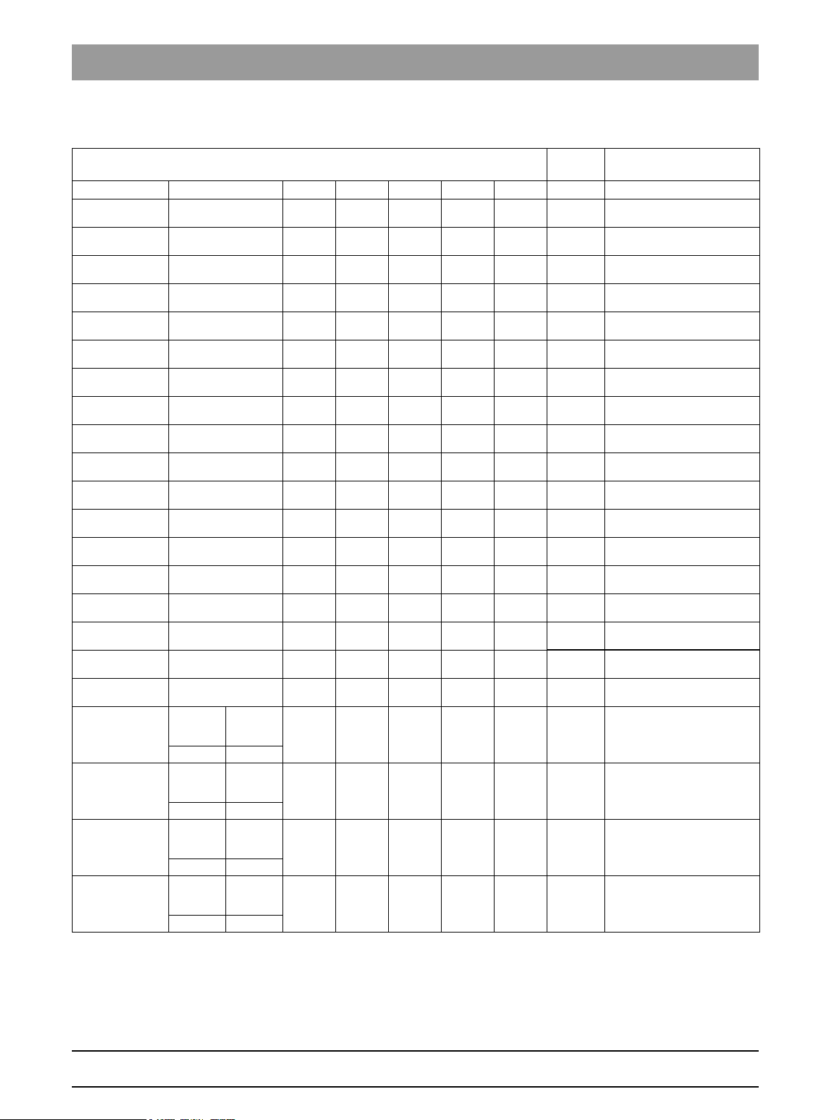
1.6.5 ORTHOPHOS XG 3D
Panoramic unit Cephalo-
Board DX6 DX7 DX11 DX61 DX81 DX91
Overall software
V 02.41.01
Overall software
V 02.51.01
Overall software
V 02.51.02
Overall software
V 02.51.03
Overall software
V 02.54
Overall software
V 02.54.01
Overall software
V 02.58.00
Overall software
V 02.58.01
Overall software
V 02.58.02
assembly
03.06.03 04.07.01
assembly
03.08.00 04.09.07
assembly
03.08.00 04.09.07
assembly
03.08.00 04.10.06
02.63 02.70 02.48 02.35 02.33 02.44
03.05.00 02.77.01 02.51.01 04.01.00 02.33.00 02.44.00
03.06.00 0277.01 02.51.02 04.01.00 02.33.00 02.44.00
03.06.00 02.77.01 02.51.03 04.01.00 02.33.00 02.44.00
03.06.01 02.80.05 02.54.00 04.02.00 02.33.00 02.44.00
Tube
1.0
Tube
1.0
Tube
1.0
Tube
1.0
Tube
assembly
2.0
Tube
assembly
2.0
Tube
assembly
2.0
Tube
assembly
2.0
02.80.05 02.54.01 04.02.00 02.33.00 02.44.00
02.82.01 02.58.00 04.04.00 02.33.00 04.45.00
02.82.01 02.58.00 04.04.00 02.33.00 04.45.00
02.82.02 02.59.07 04.04.00 02.33.00 04.45.00
* Exception: SIDEXIS version V02.00
ready
meter
/Ceph
Note
compatible with
SIDEXIS versions V01.61
compatible with
SIDEXIS versions V01.61
compatible with
SIDEXIS Version V01.61*
compatible with
SIDEXIS Version V01.61*
compatible with
SIDEXIS Version V01.61*
compatible with
SIDEXIS Version V01.61*
compatible with
SIDEXIS Version V01.61 –
V2.5*
compatible with
SIDEXIS Version V01.61 –
V2.5*
compatible with
SIDEXIS Version V01.61 –
V2.5*
Remote control
Board DX42
Overall software
V 02.41.01
Overall software
V 02.51.01
Overall software
V 02.51.02
Overall software
V 02.51.03
Overall software
V 02.54.00
Overall software
V 02.54.01
Overall software
V 02.58.00
Overall software
V 02.58.01
Overall software
V 02.58.02
Sidexis XG
V 2.5
V 2.5.3
V 2.5.6
Note Database
requires overall software version V02.41.01
or higher
requires overall software version V02.41.01
or higher
requires overall software version V02.41.01
or higher
02.52
02.54.00
02.54.00
02.54.00
02.56.02
02.56.02
02.58.02
02.58.02
02.58.02
Note
New database
59 38 399 D3352
1 – 26 D3352.076.01.26.02 09.2016
Page 35

1.7
Tab 1 1.7 Software update
NOTE
i
CAUTION
CAUTION
CAUTION
1.7 Software update
1.7.1 Important information on the software update
Read the information and "release notes" provided on the ORTHOPHOS
XG Software CD and the information on the SIRONA dealer page on the
Internet very carefully. These sources always contain the latest information on software updates.
Before performing a software update, it is essential to read the program-version-specific information in sections 1.7.3 to 1.7.5.
1.7
bеЦдблЬ
Important for XG
≥ 21001 (without ceph) / ≥ 41001 (with ceph):
A downgrade to a software version ≤V02.25 must not be performed on these
systems in any case. Such a downgrade would cause permanent and irreparable malfunctioning of the user interface!
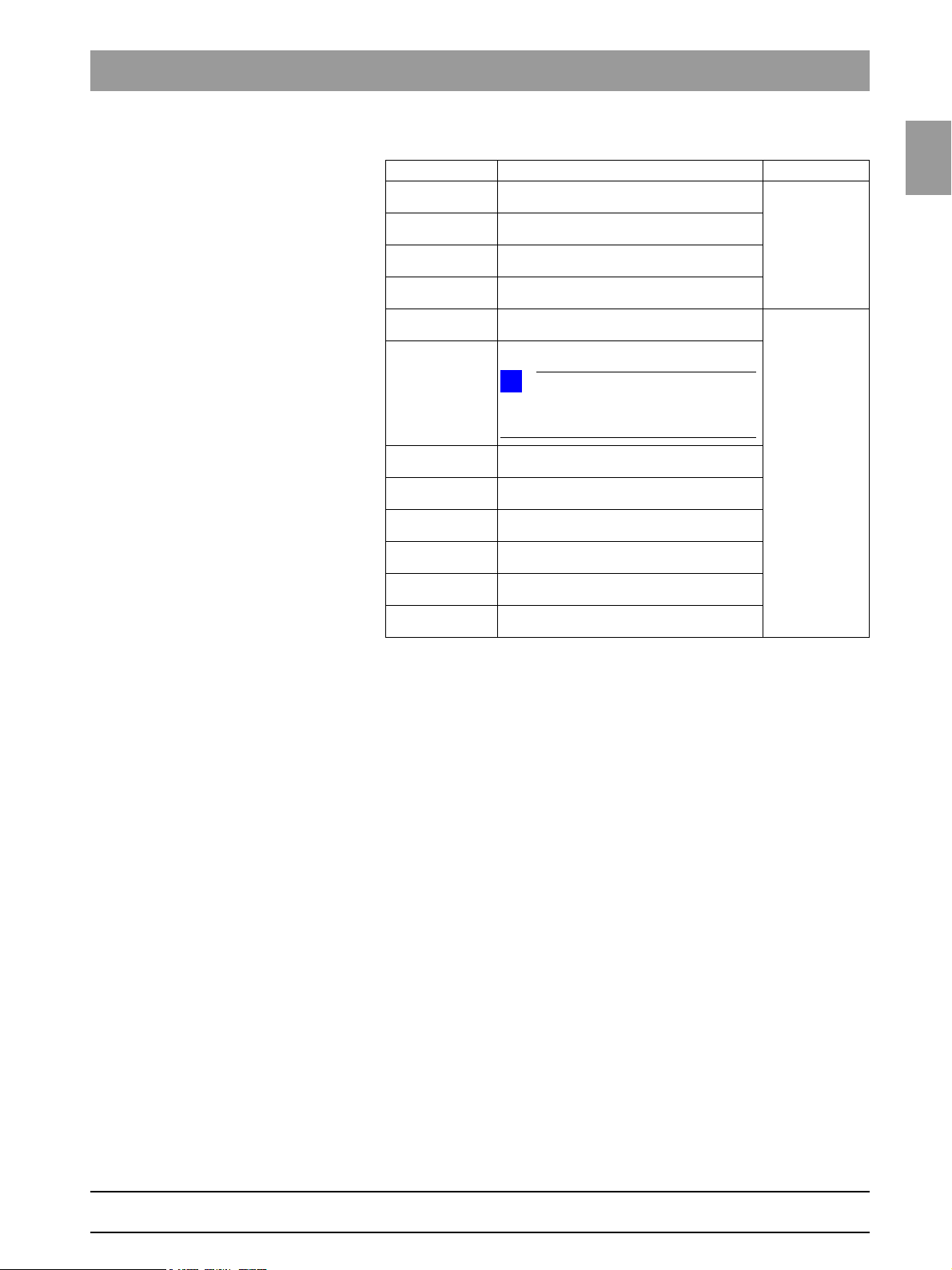
Important for units with the following serial numbers or higher:
XG 3 PPE 104000 –
XG 3 104000 –
XG 5 63500 83500
Plus
XG
A downgrade to a software version <V02.32 cannot be performed on these
units.
Plus
XG
with occlusal bite block
A downgrade to a software version <V02.40 cannot be performed on units with
an occlusal bite block.
Plus
devices with series numbers
Without ceph With ceph
23500 43500
Without ceph With ceph
24500 44500
59 38 399 D3352
D3352.076.01.26.02 09.2016
1 – 27
Page 36

1.7 Software update Tab 1
CAUTION
CAUTION
Important for units with the following serial numbers or higher:
Without ceph With ceph
XG 3 109.000 –
XG 5 69.000 89.000
ready
XG 3D
The new DX1/DX11 (REF: 62 82 052 / REF: 63 17 056) is installed in these
units. Only an overall software version
nation with these boards.
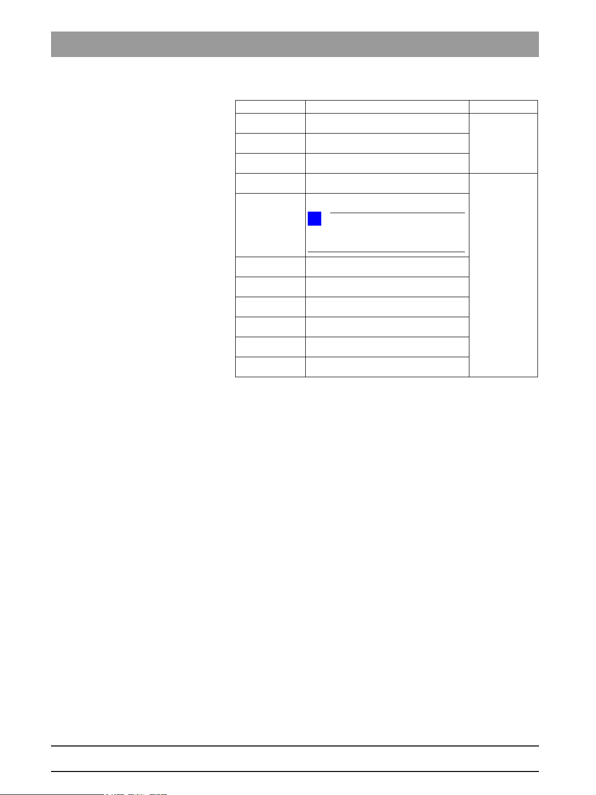
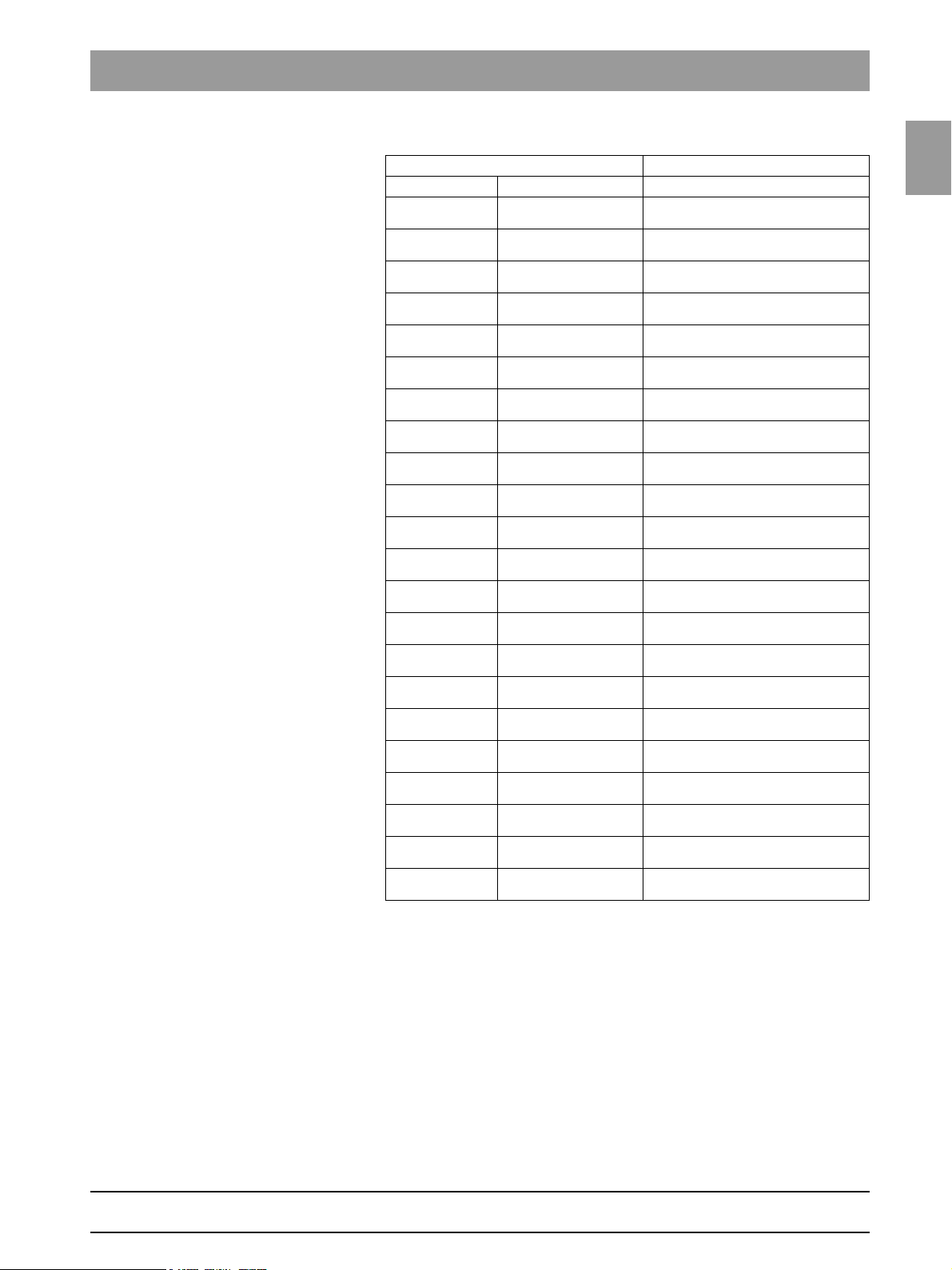
Not all software versions are suitable for all unit classes. The following table
gives you an overview of the software version permissible for each unit class.
29.000 49.000
≧
V02.51.02 can be installed in combi-
Overall
software
V 02.17 – – – X –
V 02.18.1 – – X – –
V 02.19 – – – X –
V 02.20 – – X X –
V 02.22 – – X X –
V 02.25 – X X X –
V 02.27 – X X X –
V 02.28 X X X X –
V 02.28.2 X X X X –
V 02.30 X X X X –
V 02.31 X X X X –
V 02.32 X X X X –
V 02.35 X X X X –
V 02.40 X X X X –
V 02.41 X X X X –
V 02.41.01 X X X X X
V 02.51.02 X X X X X
V 02.51.03 X X X X X
V 02.54.00 X X X X X
V 02.54.01 X X X X X
V 02.56.01 X X X X X
V 02.58.00 X X X X X
V 02.58.01 X X X X X
V 02.58.02 X X X X X
XG 3 PPE XG 3 XG 5 XG
Plus
XG
3D
ready
If an update is nevertheless performed accidentally, the version must be
downgraded again immediately before acknowledging any error messages or
executing any service routines!
1 – 28 D3352.076.01.26.02 09.2016
59 38 399 D3352
Page 37

1.7
Tab 1 1.7 Software update
NOTE
i
NOTE
i
NOTE
i
2.
4. 5.
1.7.2 Performing a software update
When updating the software from version ≤ V02.41.01 to version V02.54.01
or higher, version V02.51.03 must be installed beforehand.
1.7
1. Start SIDEXIS MANAGER under START PROGRAMS
S
IDEXIS SIDEXIS XG.
2. Click
To open the SOFTWARE UPDATE menu 3. Open the SOFTWARE UPDATE menu.
Entering the password 4. Enter the service password.
For the service password, enter the first 4 digits of the current system date in
reverse order (e.g. on 05/24/1995, 5042 must be entered as the service password.
CONFIGURATION OF THE X-RAY COMPONENTS.
Click the
The dialog box for entering the service password appears on the screen.
ATTRIBUTES tab and then SOFTWARE-UPDATE.
bеЦдблЬ
If an incorrect service password or no password at all is then entered, the limited update menu for users will then be started. This includes only the possibility for an automatic update (see page 1-31).
The dialog box for selecting the installation source opens.
Select an installation source 5. IMAGEFILE is preset as the installation source for the software update.
6. Select the path and the desired update file and confirm your selection by
clicking
Click on
The current update file can be found on the ORTHOPHOS XG Software CD. It
is delivered with each DX11 replacement board and also included in the country set. The contents of the CD can be downloaded from the Dealer domain of
the SIRONA Internet home page (under Product Info
www.sirona.com
OPEN.
NAME UPDATE and OPEN
X-ray Systems):
59 38 399 D3352
D3352.076.01.26.02 09.2016
1 – 29
Page 38

1.7 Software update Tab 1
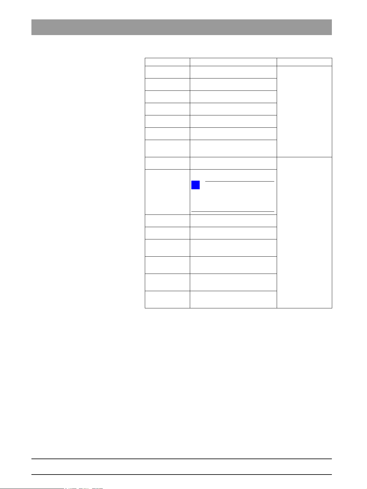
Selecting the update mode 7. Select the mode for the software update.
You can select two different update modes via the index tabs:
Automatic
The software of all components is automatically updated to a higher software version.
Main version
The software can be upgraded or downgraded to the desired version.
This update mode is required e.g. if a replacement component delivered
from stock has a newer status than the prevailing overall system status. In
this case, a main version update to the overall system status (displayed on
the info screen) must be performed for the corresponding component with
the appropriate update file (*.SUI). The module is then reprogrammed.
(For more information on the update mode, see the next page)
59 38 399 D3352
1 – 30 D3352.076.01.26.02 09.2016
Page 39

1.7
Tab 1 1.7 Software update
Automatic
A list of modules, their installed software version and the latest software
version offered by the update function is displayed in the right pane.
Main version
(e.g. if modules have a newer version status than the overall system
following module replacement)
Automatic
(accessible without password)
NOTE
i
In overall software V04.09.02 and higher, two versions of the DX6 assembly appear (tube assembly 1.0 and tube assembly 2.0).
Depending upon which tube assembly has been installed, one of the versions is displayed with a red bar and the other
with a green bar.
Modules which are connected and whose program release
corresponds to the latest main program version are identified by a continuous green bar.
Depending on the constellation, the update can take up to 10 - 15 mins.
Do not acknowledge any timeout messages before this time has elapsed!!!!!
This may lead to a total failure of individual modules.
Modules which are not elements of the current system configuration
(e.g. DX71 with XGPlus) or, as a removable medium (e.g. sensors) are not connected, are marked by a
broken red bar.
If the actual status of the module could not be polled for the update, the actual SW version
will then be displayed as = V00:00.
If a module has a hardware incompatibility to the program status to be programmed
or the software version on the module is newer than the one in the update file, this will be
indicated by a red triangle with an exclamation mark.
If the version of the selected update file is lower than the current software version of the unit,
then there will be no display in the right window. The downgrade required in this case is possible only via
User domain
Service area
1.7
bеЦдблЬ
8. Select the update mode and the update or component.
59 38 399 D3352
D3352.076.01.26.02 09.2016
1 – 31
Page 40

1.7 Software update Tab 1
NOTE
i
NOTE
i
7.
Starting the update 9. START THE UPDATE by clicking start update.
Before starting the software update, make sure that no unit movements are
active (especially any diaphragm movements)! Otherwise the system may become inoperable in rare cases.
All of the sensors located in the unit (Pan or Ceph) must be inserted in the corresponding slots. Exposure readiness must be deselected in SIDEXIS and the
system must not be in the service mode already.
The update is started. A message box informs you when the update process is completed. Confirm the update with
OK.
Checking the log file 10. Check the log file to make sure that the update was completed success-
fully.
Click SHOW LOGFILE
If messages such as Update of DXxx failed! appear there, please perform
the update again. Repeat this procedure as often as necessary until the "failed
messages" no longer appear.
1 – 32 D3352.076.01.26.02 09.2016
59 38 399 D3352
Page 41

1.7
Tab 1 1.7 Software update
CAUTION
NOTE
i
NOTE
i
SW Update Manager
11. Reboot the system.
It is always necessary to reboot the system after any software update. (The
new DX11 version will run only after the system has been rebooted (see also
Section 6.23.2, 6.22.4 Measures following replacement of boards ).
Any errors with the consecutive numbers 01, 03, 04, 06 and/or 07 displayed
immediately following the software update may be ignored. If these messages
appear again after the unit is rebooted, perform troubleshooting according to
Section 2.6.
If anything conspicuous occurs in connection with system handling on completion of the software update, please repeat the software update as the first
measure. Also check whether the system software version is displayed without an asterisk (*) on the info screen.
Checking the program versions 12. Check whether all modules contain the current program version via the
SW Update Manager
or service routine S008.2 (see page 5-53).
1.7
bеЦдблЬ
Modules which are connected and whose program status agrees with
that of the current main program version are marked by a continuous green
bar.
Modules which are not elements of the current system configuration
(e.g. DX71 with XG
nected, are marked by a broken red bar.
If the actual status of the module could not be polled for the update, the actual
SW version will then be displayed as = V00:00.
If a module has a hardware incompatibility to the program status to be programmed or the software version on the module is newer than the one in the
update file, this will be indicated by a red triangle with an exclamation mark.
If the version of the selected update file is lower than the current software version of the unit, then there will be no display in the right window. A downgrade
required in this case is possible only via the MAIN VERSION mode.
13. Open the "Details".
This generates an XML file (with the system parameters) which is filed under the network name of the system in the PDATA\Plugins\<Plugin
Name>\P2K_Config\/<Gerätename>ext.xml directory (see also section
1.8, on page 1-37).
Plus
) or, as a removable medium (e.g. sensors) are not con-
59 38 399 D3352
D3352.076.01.26.02 09.2016
1 – 33
Page 42

1.7 Software update Tab 1
NOTE
i
CAUTION
E6 15 04
R
R
1.7.3 Software update of ORTHOPHOS XG 5 to
V02.30 or higher
If the sensors previously used are to be used in the future as well, plug them
into the slots on the panoramic unit and/or cephalometer before you begin the
update.
1. Switch the unit ON.
2. Perform the software update to version V02.30 or higher
(automatic update) as described on page 1-29.
3. Turn the device OFF.
Wait for approx. 1 minute. Then switch the unit ON again.
Error message E6 15 04 (undefined activation data) is displayed.
4. Acknowledge the error message with the R key .
5. Start service routine S008.4 and enable the function activation. Exit the
Service menu again.
6. Perform a ceph adjustment if a cephalometer is installed (see chapter
4.5).
7. Turn the device OFF.
Wait for approx. 1 minute. Then switch the unit ON again.
8. Check to see which Sidexis software version is installed:
– If SIDEXIS software version V01.55 is installed, no update is required.
– If SIDEXIS software version <V01.55 or V01.6 is installed, then update
the SIDEXIS software to version V02.4 or higher.
– If a SIDEXIS software version between V02.0 and V02.3 is installed,
then SIRONA recommends updating the SIDEXIS software to version
V02.4 or higher.
When doing so, observe the system requirements for SIDEXIS V02.4. If a ≤
V01.55 software version was previously installed, the database also must be
adapted accordingly. If this is not possible, please contact the CSC.
The process is completed.
59 38 399 D3352
1 – 34 D3352.076.01.26.02 09.2016
Page 43

1.7
Tab 1 1.7 Software update
NOTE
i
NOTE
i
CAUTION
CAUTION
E6 15 04
R
R
1.7.4 Software update ORTHOPHOS XG
Plus
from version V02.20 to V02.30 or higher
If the sensors previously used are to be used in the future as well, plug them
into the slots on the panoramic unit and/or cephalometer before you begin the
update.
1. Switch the unit ON.
2. Perform the software update to version V02.25 or higher
(automatic update) as described on page 1-29.
3. Turn the device OFF.
Wait for approx. 1 minute. Then switch the unit ON again.
Error message E6 15 04 (undefined activation data) is displayed.
4. Acknowledge the error message with the R key .
5. Open the Service menu (see page 5-12).
6. Start service routine S008.3 and confirm the unit
serial number (see page 5-55).
The unit serial number is located on the rating plate of the unit.
1.7
bеЦдблЬ
In case of a wrong serial number, cancel the update and contact the SIRONA
Customer Service Center!
7. Start service routine S008.4 and enable the function activation. Exit the
Service menu again.
8. Turn the device OFF.
Wait for approx. 1 minute. Then switch the unit ON again.
9. Perform the complete system adjustment (see chapter 4):
– PAN adjustment
– For TSA units: TSA adjustment
– CEPH adjustment if cephalometer is installed
10. Check to see which Sidexis software version is installed:
– If SIDEXIS software version V01.55 is installed, no update is required.
– If SIDEXIS software version <V01.55 or V01.6 is installed, then update
the SIDEXIS software to version V02.4 or higher.
– If a SIDEXIS software version between V02.0 and V02.3 is installed,
then SIRONA recommends updating the SIDEXIS software to version
V02.4 or higher.
When doing so, observe the system requirements for SIDEXIS V02.4. If a ≤
V01.55 software version was previously installed, the database also must be
adapted accordingly. If this is not possible, please contact the CSC.
59 38 399 D3352
D3352.076.01.26.02 09.2016
The process is completed.
1 – 35
Page 44

1.7 Software update Tab 1
NOTE
i
CAUTION
1.7.5 Software update of ORTHOPHOS XG
Plus
from
version V02.22 to V02.30 or higher
If the sensors previously used are to be used in the future as well, plug them
into the slots on the panoramic unit and/or cephalometer before you begin the
update.
1. Switch the unit ON.
2. Perform the software update to version V02.30 or higher
(automatic update) as described on page 1-29.
3. Turn the device OFF.
Wait for approx. 1 minute. Then switch the unit ON again.
4. Perform a ceph adjustment if a cephalometer is installed (see chapter
4.5).
5. Check to see which Sidexis software version is installed:
– If SIDEXIS software version V01.55 is installed, no update is required.
– If SIDEXIS software version <V01.55 or V01.6 is installed, then update
the SIDEXIS software to version V02.4 or higher.
– If a SIDEXIS software version between V02.0 and V02.3 is installed,
then SIRONA recommends updating the SIDEXIS software to version
V02.4 or higher.
When doing so, observe the system requirements for SIDEXIS V02.4. If a ≤
V01.55 software version was previously installed, the database also must be
adapted accordingly. If this is not possible, please contact the CSC.
The process is completed.
59 38 399 D3352
1 – 36 D3352.076.01.26.02 09.2016
Page 45

1.8
Tab 1 1.8 Opening the "Details"
2.
1.8 Opening the "Details"
Open XG 3D
Open "Details"
1. Start SIDEXIS MANAGER under START PROGRAMS SIDEXIS
S
IDEXIS XG.
CONFIGURATION OF THE X-RAY COMPONENTS.
The CONFIGURATION OF THE X-RAY COMPONENTS MENU opens.
Click the
DETAILS.
The current parameters are read from the unit and stored as an XML file
under the network name of the unit in the
PDATA\Plugins\<Plugin Name>\P2K_Config\/<Gerätename>ext.xml directory.
The process can take up to 30 seconds.
ATTRIBUTES tab and then
Opening
2. 2.Click
MENU details 3. Open the extended DETAILS.
1.8
bеЦдблЬ
After the parameters are read, an editor displaying the XML file is opened
automatically.
59 38 399 D3352
D3352.076.01.26.02 09.2016
1 – 37
Page 46

1.8 Opening the "Details" Tab 1
NOTE
i
1951C59C.txt
--------------------------------------------------------------------------
--------------------- Changed Systemparameter ---------------------
-------------------------------------------------------------------------The following systemparameters have been changed compared to the factory
settings.
After replacing an DX11-PCB, the listed values must be reconfigured.
--- Changed System Configuration Settings --Setting of system version (configured in S17.2)
actual value: 0x0043
Setting of head rest type (configured in S17.10)
actual value: 1
Setting of language index (configured in S17.4)
actual value: 0x0001
Setting of language-set index (configured in S17.5)
actual value: 0x0002
Setting of remote control activation (configured in S17.6)
actual value: active (01)
Setting of DX41 configuration (configured in S17.9)
actual value: mounted (01)
Setting of image format (configured in S17.11)
actual value: enabled (01)
Settings of welcome-screen configuration (configured in S17.14)
actual value: 01=1, 02=1, 03=1, 04=1, 05=0, 06=0, 07=0, 08=0
Settings of CEPH-adjustment (Stored by the adjustment-routines)
actual value: DAlpha = 2810 | DX = 0 | DY = 35160
Settings of CEPH-adjustment QuickShot (Stored by the adjustment-routines)
actual value: DAlpha = 2810 | DX = 0 | DY = 35160
Settings of PAN- and TSA-adjustment (Stored by the adjustment-routines)
actual value: DAlpha = -202 | DX = -191 | DY = -6044 | A1 = 0 | A2 = 0 | C1 =
-77
Setting of ring type (configured in S34.7)
actual value: 100
Setting of kVmA level series (configured in S17.8)
actual value: FIFO_2A
Settings of network configuration
actual value: IP: 192.168.15.176 | Subnet: 255.255.255.0 | Gateway:
192.168.15.1
--- Changed User Preference Settings --Settings of patientensymbols PAN (configured in 'select basic settings')
Settings of patientensymbols CEPH (configured in 'select basic settings')
Setting of anomaly default (configured in 'select starting settings')
Setting of default patientsymbol PAN (configured in 'select starting settings')
Setting of default patientsymbol CEPH (configured in 'select starting settings')
You can scroll down further in the file using the scroll bar. The "Changed system parameters", i.e. the system parameters that were modified in relation to
the factory setting, are displayed there. This is especially interesting after a
module change. The parameter settings can thus be easily traced.
1 – 38 D3352.076.01.26.02 09.2016
59 38 399 D3352
Page 47

1.9
Tab 1 1.9 Configuring X-ray components via the SIDEXIS Manager
1.9 Configuring X-ray components via the
SIDEXIS Manager
1.9.1 Setting up the X-ray component
Since it is addressable via the network, the X-ray component can in principle
be activated for X-ray image acquisition by any of the PCs connected to the
network.
The SiXABCon program is used to manage networkable X-ray components.
It can be executed on any PC in the network, on which SIDEXIS XG has been
installed.
IMPORTANT! In order to avoid IP address conflicts, you should never operate several networkable X-ray components in the network using the same IP
address. Each X-ray component needs to be assigned a unique IP address.
Factory setting of the TCP/IP address of the unit:
192.168.15.240 (subnet mask: 255.255.255.0)
Checking existing IP addresses
To find out whether an IP address already exists in the network, enter the
"PING" function in the input prompt (DOS window).
1. Switch on all network devices (computers, printers, X-ray components)
which have been operated to date.
1.9
bеЦдблЬ
2. Invoke the input prompt (DOS window) from a network computer.
3. At the input prompt, enter "ping" followed by the address to be checked
and then press the Enter key.
Example: "ping 192.168.15.13"
– If a network device responds, then this address has already been as-
signed.
59 38 399 D3352
D3352.076.01.26.02 09.2016
1 – 39
Page 48

1.9 Configuring X-ray components via the SIDEXIS Manager Tab 1
1.9.2 Selecting an X-ray component
1. Switch all networkable X-ray components off.
2. Start the "SIDEXIS Manager" under "Start" / "Programs" / "SIDEXIS" .
3. Click "Configuration of the X-ray components".
– The menu "Configuration of the X-ray components" opens.
4. Select the "Properties" tab.
5. From the pull-down menu "Name" select the name of the desired X-ray
component ("XG3D" in the example); then click on the "Add component"
button.
or
– select the text "Add component" under the desired X-ray component
in the "Name" pull-down menu.
– The password dialog box appears.
6. Enter the service password and confirm your input by clicking the "OK"
button.
– The menu "Device configuration" opens.
– The "Boot service" element is selected automatically.
59 38 399 D3352
1 – 40 D3352.076.01.26.02 09.2016
Page 49

1.9
Tab 1 1.9 Configuring X-ray components via the SIDEXIS Manager
NOTE
i
NOTE
i
NOTE
i
Boot service
Automatic addition and setup of the X-ray component via the boot service
functions properly only if the unit is started with the default factory-set IP address.
If the IP address already has been changed, reset it to the factory setting via
service routine S037.2 or use the elements "Automatic search" or "Add component manually" (see section on "Alternatives to the boot service".
The element "Boot service" is selected in the structure tree.
1. Switch the unit on.
– The unit is detected in the network and the values for the IP address,
subnet mask and standard gateway are automatically imported to the
input fields of the menu.
If the unit is not automatically detected in the network, it is possible to manually
assign a static IP address via service routine S037.4.
1.9
bеЦдблЬ
Each unit must be assigned a unique IP address in the network.
2. If you want to, you can enter an individual IP address in the "IP address"
input field and then click into one of the other input fields with the cursor.
– Default values suitable for the IP address are automatically entered in
the "Subnet Mask" and "Standard Gateway" input fields.
3. You can either overwrite the default values in the input fields or leave them
unchanged, depending on the network involved.
4. Select the desired RCU in the "Sirona Control Server" drop-down menu.
5. Confirm the settings by clicking on the "Save Values" button.
– The settings are saved.
–The "Device Configuration" dialog window appears and informs you
that the configuration of the X-ray component has been completed successfully.
6. Confirm this dialog by clicking on the "OK" button.
7. Close the "Device configuration" menu by clicking on the "Close" button.
– The new X-ray component appears in the device list of the menu "Con-
figuration of the X-ray component" .
59 38 399 D3352
D3352.076.01.26.02 09.2016
1 – 41
Page 50

1.9 Configuring X-ray components via the SIDEXIS Manager Tab 1
Alternatives to the boot service
As an alternative to adding new X-ray components via the boot service, you
also can add them via the "Automatic search" or "Add component manually"
functions.
Automatic search
1. Select the "Automatic search" element.
– The network is searched for existing X-ray components. All X-ray com-
ponents found appear in the menu list.
2. Select the desired X-ray component from the list.
– The values for the IP address, subnet mask and standard gateway are
automatically imported to the input fields of the menu.
3. Select the desired RCU in the "Sirona Control Server" drop-down menu.
4. Confirm the settings by clicking on the "Save Values" button.
– The settings are saved.
– The "Device Configuration" dialog window appears and informs you
that the configuration of the X-ray component has been completed successfully.
5. Confirm this dialog by clicking on the "OK" button.
6. Close the "Device configuration" menu by clicking on the "Close" button.
– The new X-ray component appears in the device list of the menu "Con-
figuration of the X-ray component" .
59 38 399 D3352
1 – 42 D3352.076.01.26.02 09.2016
Page 51

1.9
Tab 1 1.9 Configuring X-ray components via the SIDEXIS Manager
Adding the component manually
1. Select the "Add component manually" element.
2. Enter the values in the menu input fields manually.
3. Select the desired RCU in the "Sirona Control Server" drop-down menu.
4. Confirm the settings by clicking on the "Save Values" button.
– The settings are saved.
–The "Device Configuration" dialog window appears and informs you
that the configuration of the X-ray component has been completed successfully.
5. Confirm this dialog by clicking on the "OK" button.
6. Close the "Device configuration" menu by clicking on the "Close" button.
– The new X-ray component appears in the device list of the menu "Con-
figuration of the X-ray component" .
1.9
bеЦдблЬ
1.9.3 Approval of the X-ray component
The X-ray component must have been selected via the "Device configuration"
menu.
1. Click on the check box in front of the X-ray component that you would like
to enable and accept the setting by clicking on the "Adopt" button.
– The X-ray component is enabled.
59 38 399 D3352
D3352.076.01.26.02 09.2016
1 – 43
Page 52

1.9 Configuring X-ray components via the SIDEXIS Manager Tab 1
Checking enablement 1. To check the communication with the unit, click the "Device info" button.
– If the unit is communicating, a logfile with information on the unit con-
figuration appears.
1.9.4 Deleting the X-ray component
1. Switch all networkable X-ray components off.
2. Start the "SIDEXIS Manager" under "Start" / "Programs" / "SIDEXIS" .
3. Click "Configuration of the X-ray components".
– The menu "Configuration of the X-ray components" opens.
4. Select the "Properties" tab.
5. From the pull-down menu "Name" select the name of the desired X-ray
component ("XG3D" in the example); then click on the "Delete component" button.
6. The X-ray component is deleted from the device list of the menu "Configuration of the X-ray component" .
59 38 399 D3352
1 – 44 D3352.076.01.26.02 09.2016
Page 53

1.10
Tab 1 1.10 The most important modules and components
Cephalometer,
arm on right side or on left
side
Remote control
(See section 1.10.4)
Slide
(See section 1.10.1)
Stand
(See section 1.10.2)
1.10 The most important modules and components
The X-ray system comprises the following main modules:
Slide with rotary unit
Stand
Cephalometer, arm on right side or on left side (optional)
Remote control (optional)
1.10
bеЦдблЬ
59 38 399 D3352
D3352.076.01.26.02 09.2016
1 – 45
Page 54

1.10 The most important modules and components Tab 1
B
A
DX11
DX1
DX5*
DX6*
DX61**
DX7*
DX81P*, DX85P*
LS*
M1*, M2*
MU
LS
LS
M AK1, M AK2
*) not available as an individual spare part (see spare parts list)
**) not for XG 3 / 3 PPE, (fixed diaphragm)
***) only for XG
Plus
/ 3D
ready
with occlusal bite block or OA ready units
DX71
Easypad (XG
Plus
/ 3D
ready
)
Multipad (XG 5 / 3 / 3 PPE)
DX51***
1.10.1 Slide
1 – 46 D3352.076.01.26.02 09.2016
59 38 399 D3352
Page 55

1.10
Tab 1 1.10 The most important modules and components
Component Designation Function
Boards DX1 Open-loop/automatic control in general
DX11 Controller board
DX5* Headrest adapter
Plus
DX51*** Occlusal bite blocks (XG
DX6* (A) Tube assembly
DX6* (B) Tube assembly
Motors M1*, M2* Linear movement of headrest
Light barriers LS Position check
1.0
2.0
DX7* Touchscreen on the Easypad (XG
DX71 LED display on Multipad (XG 5)
DX61** Diaphragm control
DX81P* Digital sensor
DX85P* Digital sensor power supply
M U Rotary movement of rotating element
AK1, AK2 Linear movement of rotating element
ready units)
Open-loop/automatic control for tube assembly
/ 3D
ready
Plus
with occlusal bite block or OA
ready
/ 3D
)
1.10
bеЦдблЬ
59 38 399 D3352
D3352.076.01.26.02 09.2016
1 – 47
Page 56

1.10 The most important modules and components Tab 1
DX41**
DX32*
M HV
1.10.2 Stand
Component Designation Function
Boards DX32* Power supply board
DX41** Interface board
Motors M HV Linear movement of height adjustment
* As of hardware version BA (from November 2006) new systems will be delivered with
the new version of board DX32 (see Section 1.9).
** As of hardware version BA (from November 2006) new systems will be delivered without
board DX41.
59 38 399 D3352
1 – 48 D3352.076.01.26.02 09.2016
Page 57

1.10
Tab 1 1.10 The most important modules and components
DX91
M S
LS
DX42
1.10.3 Cephalometer
(arm mounted on left side and on right side)
1.10
bеЦдблЬ
Component Designation Function
Boards DX91 Cephalometer control
Motors M S Stepping motors:
Linear movement of secondary diaphragm and sensor
Light barriers LS Position check
1.10.4 Remote control
59 38 399 D3352
D3352.076.01.26.02 09.2016
Component Designation Function
Boards DX42 Display board for remote control
1 – 49
Page 58

1.11 Cabling overview Tab 1
DX32 / X2
DX6 / X3
DX32 / X1
DX1 / X100
DX1 / J302
DX6 / J6
1
2
3
4
5
4
DX1
DX6
5
3
1
2
Line filter
DX32
Power switch
Wago terminal
DX1 / J306 – J302
DX6 / J2 – J3
DX1 / J901
DX41
DX1 / X303
DX41 / X100
DX1 / X104
DX7 / X102
DX1 / X302
DX7 / X103
DX1 / X102
DX61 / X501
6
7
8*
9
10
11
10
DX1
DX41**
DX61
DX6
DX7/DX71
6
11
7
8/108*
9
* as of unit hardware version BA
** Board DX 41 omitted in unit HW version
BA and higher
108*
1.11
Cabling overview
1 – 50 D3352.076.01.26.02 09.2016
59 38 399 D3352
Page 59

1.11
Tab 1 1.11 Cabling overview
DX1 / X306
DX61 / X101
DX1 / X404
DX5 / X1
DX1 / X610
DX1 / X403
18
DX5
DX61
12
DX1
DX81
MHV
LS
sensor
13
19
16
12
13
16
18
19
1.11
bеЦдблЬ
59 38 399 D3352
D3352.076.01.26.02 09.2016
1 – 51
Page 60

1.11 Cabling overview Tab 1
DX1
23
21
38
DX61
25
DX41**
DX42
DX81
35
22/24***
212131
Potentiometer
DX91
MU
LS
sensor
Laser module
Media converter
DX42 / X100
DX41 / X103
DX61
DX91
DX5
DX41
Media Konverter
DX81 / X100
DX1 / X503
17
17/117*
21
22
23
25
31
35
38
* as of unit hardware version BA
** Board DX 41 omitted in unit HW version
BA and higher
*** with ceph units with unit HW version BA and higher
117*
/24***
DX61
24***
59 38 399 D3352
1 – 52 D3352.076.01.26.02 09.2016
Page 61

1.11
Tab 1 1.11 Cabling overview
DX91
36
39
DX1
40
37
DX91 / X6
DX91 / X101
DX1 / X103
DX1 / X309
36
37
39
40
41
DX51
41
1.11
bеЦдблЬ
59 38 399 D3352
D3352.076.01.26.02 09.2016
1 – 53
Page 62

1.12 Illustrations of boards Tab 1
DX1
DX11
X500
X307X503
X303
X104
X403
X611
X607
X306X302
J307
J306
J302
X402
X1000
X102
X103
X404
X804
X802
X803
X100
X811
X812
X813
X610
X309
1.12
Illustrations of boards
1.12.1 Boards in the slide
Boards DX1 / DX11 Installed up to unit serial number:"
ORTHOPHOS XG 3 108.999
ORTHOPHOS XG 5 68.999
ORTHOPHOS XG 5 / Ceph 88.999
ORTHOPHOS XG 3D
ORTHOPHOS XG 3D
ready
ready
/ Ceph
To facilitate cable routing to the side, RJ 45 connectors with a 45° incline were introduced in August 2006.
28.999
48.999
59 38 399 D3352
1 – 54 D3352.076.01.26.02 09.2016
Page 63

1.12
Tab 1 1.12 Illustrations of boards
Boards DX1 / DX11 Installed as of unit serial number:"
ORTHOPHOS XG 3 109.000
ORTHOPHOS XG 5 69.000
ORTHOPHOS XG 5 / Ceph 89.000
ORTHOPHOS XG 3D
ORTHOPHOS XG 3D
ready
ready
/ Ceph
29.000
49.000
1.12
bеЦдблЬ
59 38 399 D3352
D3352.076.01.26.02 09.2016
1 – 55
Page 64

1.12 Illustrations of boards Tab 1
X3
X4
X6 X1 X2
X5X7
X1
L1
Board DX5
Board DX51 (only XG
Plus
/ 3D
ready
)
1 – 56 D3352.076.01.26.02 09.2016
59 38 399 D3352
Page 65

1.12
Tab 1 1.12 Illustrations of boards
X2X1 X306X305
J2
J3
J6
S2
X3
F201
Board DX6 in the X-ray tube assembly 1.0 (not available as a spare part)
1.12
bеЦдблЬ
59 38 399 D3352
D3352.076.01.26.02 09.2016
1 – 57
Page 66

1.12 Illustrations of boards Tab 1
Board DX6 in the X-ray tube assembly 2.0 (not available as a spare part)
59 38 399 D3352
1 – 58 D3352.076.01.26.02 09.2016
Page 67

1.12
Tab 1 1.12 Illustrations of boards
NOTE
i
X501
X101
X203
X202
X406
X405
X402 X401
X400 X304
X303
X302 X301
X300 X200
X201
Board DX61 (not for XG 3/3 PPE)
1.12
bеЦдблЬ
Board DX7 (only XG
Plus
/ 3D
ready
, not available as spare part)
Board DX7 is shown here only for enhanced clarity. The Easypad may be replaced only as a complete unit!
59 38 399 D3352
D3352.076.01.26.02 09.2016
1 – 59
Page 68

1.12 Illustrations of boards Tab 1
NOTE
i
X104
X203
X202
X106
X103 X102
Board DX71 (only XG 5 / 3 / 3 PPE, not available as a spare part)
Board DX71 is shown here only for enhanced clarity. The Multipad may be
replaced only as a complete unit!
1 – 60 D3352.076.01.26.02 09.2016
59 38 399 D3352
Page 69

1.12
Tab 1 1.12 Illustrations of boards
NOTE
i
CAUTION
DX81
DX85
Boards DX81P / DX85P (not available as spare parts)
1.12
bеЦдблЬ
Boards DX81 and DX85 are shown here only for enhanced clarity.
It is not allowed to open the sensor! The sensor may be replaced only as
a complete unit!
59 38 399 D3352
D3352.076.01.26.02 09.2016
1 – 61
Page 70

1.12 Illustrations of boards Tab 1
X100
F100X1
F101 F102 F103
X2
X100
F100X1
F101 F102
X2
1.12.2 Boards in the stand
Board DX32
up to unit hardware version AG
Board DX32
as of unit hardware version BA
(from November 2006)
1 – 62 D3352.076.01.26.02 09.2016
59 38 399 D3352
Page 71

1.12
Tab 1 1.12 Illustrations of boards
X100
X103
X104X102
X501
X101
X202
X304
X302
X201
X407
X306X307X308
Board DX41
omitted as of unit hardware version BA
(from November 2006)
1.12
bеЦдблЬ
Board DX91
1.12.3 Boards in the cephalometer
(arm mounted on left side and on right side)
59 38 399 D3352
D3352.076.01.26.02 09.2016
1 – 63
Page 72

1.12 Illustrations of boards Tab 1
X200
X201
X107
X101
X100
X105
V103
V100
V101
1.12.4 Boards in the remote control
Board DX42
up to unit hardware version AG
59 38 399 D3352
1 – 64 D3352.076.01.26.02 09.2016
Page 73

1.12
Tab 1 1.12 Illustrations of boards
X200
X201
X107
X101
X108 X105 Jumpers X109 and X110
V100
V103
V101
Board DX42
as of unit hardware version BA
(from November 2006)
1.12
bеЦдблЬ
59 38 399 D3352
D3352.076.01.26.02 09.2016
1 – 65
Page 74

1.13 Remove covers Tab 1
13
12
6
7
1
2
8
9
3
4
11
10
5
14
1. Profile cover
2. Intermediate piece
3. Arm cover, top
4. Slide cover, top rear
5. Slide cover, bottom rear
6. Support cover, top
7. Support cover, bottom
8. Tube assembly cover, front
9. Tube assembly cover, rear
10. Slide cover, center rear
11. Sensor holder cover
12. Slide cover, front complete
13. Ring cover
14. Cephalometer cover
1.13
Remove covers
1 – 66 D3352.076.01.26.02 09.2016
59 38 399 D3352
Page 75

ORTHOPHOS XG
2 Messages
Page 76

Tab 2
Contents
2.1 Help messages .......................................................2 – 4
2.2 System messages...................................................2 – 6
2.3 Status displays ........................................................2 – 6
2.4 Error messages.......................................................2 – 6
2.4.1 Ex yy zz................................................................ 2 – 7
2.4.2 Ex yy zz................................................................ 2 – 8
2.4.3 Ex yy zz ................................................................ 2 – 8
2.4.4 General handling of error messages .................... 2 – 8
2.5 List of error messages.............................................2 – 9
2.6 List of available service routines ...........................2 – 59
59 38 399 D3352
2 – 2 D3352.076.01.26.02 09.2016
Page 77

Tab 2
2 Messages
The different message texts are displayed...
For XG
For XG 5 / 3 / 3 PPE: on the Multipad display
on the display of the remote control
There are 3 groups of message texts:
Help messages (Hx xx)
Error messages (Ex yy zz)
Plus
– Help messages are caused by operator errors
– The user must take action
– Error messages indicate system faults
– The user must take action to eliminate the fault(s)
/ 3D
ready
: on the Easypad touchscreen
bеЦдблЬ
System messages (Sxxx)
– System messages inform the user about the current operating
status of the system
– The user is not required to take action
59 38 399 D3352
D3352.076.01.26.02 09.2016
2 – 3
Page 78

2.1 Help messages Tab 2
NOTE
i
NOTE
i
2.1
Help messages are displayed as help codes (Hxxx) on the touchscreen of the
Easypad (XG
on the remote control display (if available). The codes tell you how to operate
the system if radiation release is not possible due to a previous operator error.
The following list provides you with an overview of all help codes, their meaning and the action required to eliminate the corresponding problems:
Help messages
Plus
/ 3D
ready
), on the display of the Multipad (XG5/3/3 PPE) or
Help code Description Actions required
H3 01
H3 10
H3 20
H3 21
H3 22
(only for XG
Plus
H3 30
(XG 3 PPE only)
H3 31
The rotating element on the panoramic unit is
not located in its starting position.
The system is performing an action.
The exposure parameters have not been
acknowledged yet.
The X-ray room door contact is not detected.
Quadrant for TSA exposure is not selected.
)
Indicates number of exposures remaining
(PPE concept).
1. After each power-up (see S017.22)
2. After each exposure if the number of exposures remaining is below the defined warning
level (see S017.23)
No further exposures available.
Press the R key:
Panoramic unit moves to starting position.
Wait until the system is ready.
Press the R key:
Exposure data are confirmed.
Close the door or check door contact.
Select quadrant via Easypad.
Request new activation code via Sirona
Customer Service Center (CSC) in due
time.
Enter new "activation code".
(XG 3 PPE only)
H4 01
The sensor on the panoramic unit is not properly
plugged in or is missing.
Plug sensor into PAN slot.
H4 02
H4 03
H4 04
H4 05
H4 06
H4 07
The sensor on the cephalometer is not properly
plugged in or is missing.
SIDEXIS is not ready for exposure.
The sensor does not match the selected exposure type
The sensor does not match the selected exposure type
The cephalometer is not located in its starting
position.
Unit uses default settings for this exposure,
since the settings specified by SIDEXIS cannot
be taken over.
If this message does not disappear after the
sensor is plugged in, this indicates a system error. Perform error diagnostics according to Section 3.2.
Plug sensor into Ceph slot.
If this message does not disappear after the
sensor is plugged in, this indicates a system error. Perform error diagnostics according to Section 3.2.
Make SIDEXIS ready for exposure.
Plug in the ceph sensor.
Plug in the TSA sensor.
Press the R key:
Cephalometer moves to starting position.
Perform alternative program setting.
2 – 4 D3352.076.01.26.02 09.2016
59 38 399 D3352
Page 79

Tab 2 2.1 Help messages
NOTE
i
CAUTION
Help code Description Actions required
H4 10
H4 20
The sensor is being queried.
The image could not be transferred to SIDEXIS.
Wait until the message disappears.
Retrieve the exposure with SiRescue (see
SIDEXIS Operator’s Manual).
Do not switch the system off until the help message has disappeared.
The above measures clear those help messages that result from operator errors. If it is not possible to clear the help message by taking the above measures, another type of error is the cause. To identify the error, proceed as described in section 2.5.
bеЦдблЬ
2.1
59 38 399 D3352
D3352.076.01.26.02 09.2016
2 – 5
Page 80

2.2 System messages Tab 2
Ex yy zz
Error type
“Troubleshooting”
classification for the
Location
Module, subsystem or logical function unit
Sequential number
with identification
of the error
2.2
System messages
System code Description Actions required
S100
S110
ORTHOPHOS XG is started
Exposure cannot be performed.
Wait, no action required
Quit readiness for exposure,
switch unit OFF, wait for 1 minute, switch
unit back ON and observe error messages
displayed after switch-on.
Repeat procedure if necessary
2.3 Status displays
Status displays
(only for XG
Plus
/ 3D
ready
)
Ready for exposure
Please wait
Ready for exposure in XX seconds
Exposure in progress
Description
The unit is ready for operation.
The unit waiting for operational readiness.
The cooling time countdown is running.
Radiation is released.
2.4 Error messages
Error messages are displayed as error codes (Ex yy zz) on the touchscreen
of the Easypad (XG
PPE) or on the remote control display (if available).
The codes provide you with error type, error location and troubleshooting
information.
Error code: Ex yy zz The error messages are encoded according to the following pattern:
The error messages are sorted by modules in the table on page 2-7.
Plus
/ 3D
ready
), on the display of the Multipad (XG5 / 3 / 3
2 – 6 D3352.076.01.26.02 09.2016
59 38 399 D3352
Page 81

Tab 2 2.4 Error messages
2.4.1 Ex yy zz
Identifier x is supposed to help you quickly reach a decision on how to proceed with this error.
x Description Error group Actions required
System warning;
1
System message
Errors caused by sys-
2
tem overload
The system detects
3
that a key was pressed
during power-on
Malfunction or
4
mechanical obstruction
of unit movements
Malfunction during the
5
exposure or during
exposure preparation
6
Error during system
self-test
7
Unrecoverable system error
This error group includes all errors that indicate still acceptable tolerance variations, or
messages about states which do not directly
affect system operation.
This error group includes states that indicate
e.g. temporary excess temperatures or the
like. The cause of the error disappears
automatically after a certain waiting time.
This error group includes all errors that indicate invalid signal states of keys and safety
signals during power-on.
This error group includes all errors that indicate problems with the motor-controlled
movements on the outside of the unit.
This error group includes all errors resulting
from a certain system action triggered by the
user which could not be performed because
a required (internal) partial function (software or hardware) is not ready or fails.
This error group includes all errors which
may occur spontaneously and without any
related operator action. They may be
caused by system self-tests.
This error group includes all errors which
may occur spontaneously and without any
related operator action. They may be
caused by system self-tests. In this case it is
absolutely sure that continued system operation is not possible.
Acknowledge the error message to con-
tinue system operation. If the error occurs repeatedly, switch the system OFF
and back ON.
If the error occurs again: Identify the error
by proceeding as described in section
2.5.
Acknowledge the error message.
Repeat the procedure step after a certain
waiting time.
– If the error message reappears: Ex-
tend the waiting time.
– If the error state persists: Identify the
error by proceeding as described in
section 2.5.
Switch the unit off and on again.
If the error occurs again, identify the error
by proceeding as described in section
2.5.
Acknowledge the error message and
make sure that the movements of the unit
are not obstructed.
Repeat the last procedure step or expo-
sure. If the error reoccurs without any
identifiable cause: Identify the error by
proceeding as described in section 2.5.
Acknowledge the error message.
Repeat the last procedure step or expo-
sure. If the error occurs again: Identify
the error by proceeding as described in
section 2.5.
Acknowledge the error message.
Identify the error by proceeding as de-
scribed in section 2.5.
Note:
Further operation of the unit is possible.
Identify the error by proceeding as de-
scribed in section 2.5.
bеЦдблЬ
2.4
59 38 399 D3352
D3352.076.01.26.02 09.2016
2 – 7
Page 82

2.4 Error messages Tab 2
2.4.2 Ex yy zz
Identifier yy defines the location or logical function unit where the error has
occurred.
yy Location/Function unit Board
06
61
07
71
10
11
12
13
14
15
41
42
81
91
Tube assembly DX6
Diaphragm control (not for XG 3/3 PPE, fixed diaphragm) DX61
User interface on the Easypad (XG
User interface on the Multipad (XG 5 / 3 / 3 PPE) DX71
System hardware DX11 / DX1
System software DX11 / DX1
CAN bus DX11 / DX1
Stand peripherals DX11 / DX1
Digital extension DX11 / DX1
Configuration/update (wrong software, wrong module constellation, etc.) DX11 / DX1
Media interface card (omitted as of HW version BA, November 2006) DX41
Remote control DX42
Sensor (Pan slot: zz=1-23 ; ceph slot: zz= 51-73) DX81
Cephalometer DX91
Plus
/ 3D
ready
)DX7
The location may be a DX module number standing for an entire HW function
unit, or a logical SW function unit on board DX11 (central control).
2.4.3 Ex yy zz
The identifier zz represents a consecutive number with the error
identification.
2.4.4 General handling of error messages
Error messages must always be acknowledged with the R key.
If trouble-free operation is possible after the error is acknowledged, then no
further action is necessary.
If error messages reoccur or occur frequently, identify the error as described
in section 2.5 and take appropriate action to eliminate the corresponding error
or fault.
In some cases, it may make sense to obtain more information on the history
and frequency of errors via the error logging memory (S007) and
(see section 1.8, on page 1-37) (see also section 3.1).
DETAILS
59 38 399 D3352
2 – 8 D3352.076.01.26.02 09.2016
Page 83

Tab 2 2.5 List of error messages
NOTE
i
2.5 List of error messages
In the following table, the error codes are sorted by the location or function unit
where the error has occurred. For enhanced clarity, the corresponding ID in
the error code is printed in bold type.
Location 06: Tube assembly / DX6 board
bеЦдблЬ
Error code Description Actions required see page
E6 06 01
E6 06 02
E6 06 03
E6 06 04
E6 06 05
E6 06 06
General error during module initialization
Invalid system data or uninitialized
module storage data
Invalid commanding of control data,
CAN bus error
Note:
This error may also occur in connection with other causal error messages!
Please also observe the causal error
message! It appears only after you
acknowledge the first error message.
Data transfer error or dialog error to
module (master side)
Data transfer error or dialog error to
bootloader of module
Note:
Occurs only in connection with software update
Module failed in TTP*
(detected on master side)
Note:
This error may also occur in connection with other causal error messages.
Please also observe the causal error
message! It appears only after you
acknowledge the first error message.
Please contact the Sirona Customer Service
Center (CSC) to find out whether a bugfix by
means of a software update is possible and perform such an update if necessary.
If the error occurs frequently,
replace the X-ray tube assembly
Perform service routine S005.2
Please contact the Sirona Customer Service
Center (CSC) to find out whether a bugfix by
means of a software update is possible and perform such an update if necessary.
Check the CAN bus
Please contact the Sirona Customer Service
Center (CSC) to find out whether a bugfix by
means of a software update is possible and perform such an update if necessary.
Check the CAN bus
Please contact the Sirona Customer Service
Center (CSC) to find out whether a bugfix by
means of a software update is possible and perform such an update if necessary.
Repeat software update
Check the CAN bus
If the error occurs repeatedly or the module is
no longer addressable,
Replace the X-ray tube assembly
Check the CAN bus
Please contact the Sirona Customer Service
Center (CSC) to find out whether a bugfix by
means of a software update is possible and perform such an update if necessary.
If the error occurs repeatedly or the module is
no longer addressable,
Replace the X-ray tube assembly
1-27
6-48
6-33
1-27
1-27
1-27
1-27
6-48
1-27
6-48
2.5
3-6
3-6
3-6
3-6
59 38 399 D3352
D3352.076.01.26.02 09.2016
2 – 9
Page 84

2.5 List of error messages Tab 2
Error code Description Actions required see page
E6 06 07
E6 06 08
E7 06 10
E7 06 12
E6 06 13
E2 06 20
TTP* timeout error
(detected on slave side)
Note:
The module was temporarily not
addressed by the master:
- Undervoltage on the master side
- Procedure error in the software
- Master (DX11) receives no
Return commanding from the module
Note:
This error may also occur in connection with other causal error messages!
Please also observe the causal error
message! It appears only after you
acknowledge the first error message.
General fault detected locally on module (slave side). CAN controller being
reinitialized.
Module is stuck in bootloader stage
Unit is not ready for operation
Note:
This error may also occur in connection with other causal error messages!
Please also observe the causal error
message! It appears only after you
acknowledge the first error message.
Error when writing to EEPROM
Note:
Stored data may be lost
Overtemperature of single tank/power
pack
Check the CAN bus
Check power supply of board DX11; measuring
point 3.3 V on board DX1 (see wiring diagrams).
– If 3.3V present, replace board
DX11
– If 3.3V not present, replace board
DX11
– Check cable L6,
replace if necessary
– Check tube assembly (DX6)
replace if necessary
Check the CAN bus
Check software versions via info screen or ser-
vice routine S008.2,
if necessary, perform a software update
Please contact the Sirona Customer Service
Center (CSC) to find out whether a bugfix by
means of a software update is possible and perform such an update if necessary.
Replace the X-ray tube assembly
Check board DX6 (note LED states)
If the board remains in the bootloader stage...
Repeat software update
Replace the X-ray tube assembly
Check the CAN bus
If this error occurs in combination with other errors
System restart:
Switch the unit off. Wait 1 minute.
Switch the unit ON.
Repeat procedure and observe causal error
messages.
Replace the X-ray tube assembly
Acknowledge error and repeat procedure
If the error occurs again...
Replace the X-ray tube assembly
Wait until the X-ray tube assembly has cooled
down.
Check fan function using service routine
S005.4;
3-6
6-73
6-73
3-18
6-101
6-48
3-6
5-53
1-27
1-27
6-48
3-12
1-27
6-48
3-6
6-48
6-48
5-35
if necessary, Replacing fan
Check temperature sensor in single tank
Check service routine S005.5,
if necessary, Replace the X-ray tube assembly
59 38 399 D3352
6-53
5-37
6-48
2 – 10 D3352.076.01.26.02 09.2016
Page 85

Tab 2 2.5 List of error messages
Error code Description Actions required see page
E6 06 21
E6 06 22
E3 06 23
E5 06 30
E5 06 31
E5 06 32
E1 06 40
E1 06 41
E1 06 42
E1 06 43
E1 06 44
E1 06 45
Hardware signal of release button not
detected
Broken temperature sensor
Hardware signal of release button
applied during power-on
Total radiation time exceeded If a CAN bus error had been reported before...
Partial radiation time exceeded If a CAN bus error had been reported before...
Minimum preheating time not
observed
Tolerance exceeded: Preheating (VH)
- nom.
Tolerance exceeded: kV - nom.
Tolerance exceeded: mA - nom.
Tolerance exceeded: Preheating (VH)
- act.
Tolerance exceeded: kV - act.
Tolerance exceeded: mA - act.
Check cable L5 (fiber optic cable),
replace if necessary
Replacing board DX1
Replace the X-ray tube assembly
Replace the X-ray tube assembly
Check cable L5:
– Switch the unit off.
– Pull cable L5 off of tube assembly
– Switch on the unit
– Perform optical check of L5:
- If light is visible: Replacing board DX1
- If no light is visible, replace the tube assembly
Check the CAN bus
Please contact the Sirona Customer Service
Center (CSC) to find out whether a bugfix by
means of a software update is possible and perform such an update if necessary.
Check the CAN bus
Please contact the Sirona Customer Service
Center (CSC) to find out whether a bugfix by
means of a software update is possible and perform such an update if necessary.
If a CAN bus error had been reported before...
Check the CAN bus
Please contact the Sirona Customer Service
Center (CSC) to find out whether a bugfix by
means of a software update is possible and perform such an update if necessary.
Perform service routine S005.2
Replace the X-ray tube assembly
Perform service routine S005.2
Replace the X-ray tube assembly
Perform service routine S005.2
Replace the X-ray tube assembly
Perform service routine S005.2
Replace the X-ray tube assembly
Perform service routine S005.2
Replace the X-ray tube assembly
Perform service routine S005.2
Replace the X-ray tube assembly
3-18
6-101
6-73
6-48
6-48
6-73
6-48
3-6
1-27
3-6
1-27
3-6
1-27
5-33
6-48
5-33
6-48
5-33
6-48
5-33
6-48
5-33
6-48
5-33
6-48
bеЦдблЬ
2.5
59 38 399 D3352
D3352.076.01.26.02 09.2016
2 – 11
Page 86

2.5 List of error messages Tab 2
Error code Description Actions required see page
E6 06 50
E6 06 51
E6 06 52
E6 06 53
E6 06 55
E7 06 54
E6 06 56
Undervoltage in intermediate circuit
(400 V)
VHmax
MAmax
KVmax
Anode voltage too low
Basic heating pulses not applied
Error during auto-compensation
*) TTP = Time Trigger Protocol
Check fuse F201 on board DX6 (see wiring dia-
grams), replace if necessary
Check cable L3 (tube assembly),
replace if necessary
Check electronic fuse on board DX32:
– Switch the unit off.
– Wait for at least 7 minutes (due to electronic
fuse)
– Switch unit back ON
– Functional test
If the error occurs again...
Check board DX32,
replace if necessary
Perform service routine S005.2
Replace the X-ray tube assembly
Perform service routine S005.2
Replace the X-ray tube assembly
Perform service routine S005.2
Replace the X-ray tube assembly
Replace the X-ray tube assembly
Replace the X-ray tube assembly
Please contact the Sirona Customer Service
Center (CSC) to find out whether a bugfix by
means of a software update is possible and perform such an update if necessary.
Let the tube assembly cool down for approx. 30
min and repeat this procedure.
If the error occurs again...
Replace the X-ray tube assembly
3-18
6-101
3-12
6-73
5-33
6-48
5-33
6-48
5-33
6-48
6-48
6-48
1-27
6-48
59 38 399 D3352
2 – 12 D3352.076.01.26.02 09.2016
Page 87

Tab 2 2.5 List of error messages
Location 07 (XG
Plus
/ 3D
ready
): Easypad / board DX7
Error code Description Actions required see page
E6 07 01
E6 07 02
E6 07 03
E6 07 04
E6 07 05
E6 07 06
General error during module initialization
Invalid system data or uninitialized
module storage data
Invalid commanding or control data
Note:
This error may also occur in connection with other causal error messages.
Please also observe the causal error
message! It appears only after you
acknowledge the first error message.
Data transfer error or dialog error to
module (master side)
Data transfer error or dialog error to
bootloader of module
Note:
Occurs only in connection with
software update to
Module failed in TTP*
(detected on master side)
Note:
This error may also occur in connection with other causal error messages.
Please also observe the causal error
message! It appears only after you
acknowledge the first error message.
Please contact the Sirona Customer Service
Center (CSC) to find out whether a bugfix by
means of a software update is possible and perform such an update if necessary.
If the error occurs again...
Check user interface with electronics (DX7) or
Replace Easypad
Please contact the Sirona Customer Service
Center (CSC) to find out whether a bugfix by
means of a software update is possible and perform such an update if necessary.
Acknowledge error and repeat procedure
If the error occurs again...
Check user interface with electronics (DX7) or
Replace Easypad
Check the CAN bus
Please contact the Sirona Customer Service
Center (CSC) to find out whether a bugfix by
means of a software update is possible and perform such an update if necessary.
Check the CAN bus
Please contact the Sirona Customer Service
Center (CSC) to find out whether a bugfix by
means of a software update is possible and perform such an update if necessary.
Repeat software update
Check the CAN bus
Check user interface with electronics (DX7) or
Replace Easypad
Check the CAN bus
Please contact the Sirona Customer Service
Center (CSC) to find out whether a bugfix by
means of a software update is possible and perform such an update if necessary.
Replace Easypad
1-27
3-12
6-26
1-27
3-12
6-26
3-6
1-27
3-6
1-27
1-27
3-6
6-73
6-26
3-6
1-27
6-26
bеЦдблЬ
2.5
59 38 399 D3352
D3352.076.01.26.02 09.2016
2 – 13
Page 88

2.5 List of error messages Tab 2
Error code Description Actions required see page
E6 07 07
E6 07 08
E7 07 10
E7 07 12
E6 07 20
TTP* timeout error
(detected on slave side)
Note:
The module was temporarily not
addressed by the master:
- Undervoltage on the master side
- Procedure error in the software
- Master (DX11) receives no
Return commanding from the module
Note:
This error may also occur in connection with other causal error messages.
Please also observe the causal error
message! It appears only after you
acknowledge the first error message.
General fault detected locally on module (slave side). CAN controller being
reinitialized.
Module is stuck in bootloader stage
Unit is not ready for operation.
Note:
Therefore, the error can only be displayed on the remote control (DX42).
Contact to DX11 interrupted during
operation.
Check the CAN bus
Check power supply of board DX11; measuring
point 3.3 V on board DX1 (see wiring diagrams).
– If 3.3V present, replace board
DX11
– If 3.3V not present, replace board
DX11
Check the CAN bus
Check software versions via info screen or ser-
vice routine S008.2,
if necessary, perform a software update
Check user interface with electronics (DX7) or
Replace Easypad
Please contact the Sirona Customer Service
Center (CSC) to find out whether a bugfix by
means of a software update is possible and perform such an update if necessary.
Check user interface with electronics (DX7)
(observe LED statuses)
If the board remains in the bootloader stage...
Repeat software update
Check user interface with electronics (DX7) or
Replace Easypad
Check the CAN bus
This error is a sequential fault.
System restart:
Switch the unit off. Wait 1 minute.
Switch the unit ON.
Repeat procedure and observe causal error
messages.
Note error message on remote control (DX42)
and check log memory (via details).
Check the CAN bus
Check cable L9,
replace if necessary
3-6
6-73
6-73
3-6
5-53
1-27
6-73
6-26
1-27
3-12
1-27
6-73
6-26
3-6
3-6
3-18
6-101
59 38 399 D3352
2 – 14 D3352.076.01.26.02 09.2016
Page 89

Tab 2 2.5 List of error messages
NOTE
i
Error code Description Actions required see page
E7 07 21
E3 07 30
E3 07 31
E3 07 32
E3 07 33
E3 07 34
E3 07 35
E3 07 36
E6 07 40
No CAN bus connection.
DX11 does not start.
Note:
Occurs in the start screen after poweron.
Height adjustment keys actuated during power-on
Forehead support key pressed during
power-on
Temple support keys actuated during
power-on
Light localizer key actuated during
power-on
Test key actuated during power-on
Return key actuated during power-on
Touchscreen actuated during poweron
No valid language set found
Start detail query
If DX11 responds...
Check signal path to DX7,
if necessary, repair or replace cable/connector
Replace DX1
If DX11 does not respond ...
Replace DX11
System restart:
Switch the unit off. Wait 1 minute.
Switch unit ON, making sure that the Easypad
is not actuated during boot-up.
If the error occurs again...
Check user interface with electronics (DX7) or
Replace Easypad
Check selected language set using service rou-
tine S017.5, correct if necessary
6-101
6-73
6-73
6-73
6-26
5-93
1-27
bеЦдблЬ
2.5
Check whether selected language set is already installed, perform software update if necessary.
Please contact the Sirona Customer Service
Center (CSC) to find out whether a bugfix by
means of a software update is possible and perform such an update if necessary.
*) TTP = Time Trigger Protocol
1-27
59 38 399 D3352
D3352.076.01.26.02 09.2016
2 – 15
Page 90

2.5 List of error messages Tab 2
NOTE
i
NOTE
i
Location 10: System hardware
Error code Description Actions required see page
E7 10 01
E7 10 02
E1 10 03
EEPROM cannot be written.
FPGA* of DX1 is not addressable.
The flash file system must be formatted.
Acknowledge error and repeat procedure
If the error occurs again...
Replace board DX11
Replace board DX1
Acknowledge error
6-73
6-73
E1 10 04
E1 10 05
Note:
Occurs after replacement of board
DX11.
Flash file system formatting in progress.
Flash file system is not ready for operation.
*) FPGA = Field Programmable Gate Array
The flash file system is formatted and error message
E1_10_04 is displayed.
Wait until the message automatically disap-
pears (approx. 2 - 3 min.)
Run service routine S009.4 and
Format flash file system
The contents of the error memory are thus lost.
If the error occurs again...
Replace board DX11
5-61
6-73
2 – 16 D3352.076.01.26.02 09.2016
59 38 399 D3352
Page 91

Tab 2 2.5 List of error messages
Location 11: Power PC, board DX11
Error code Description Actions required see page
E6 11 01
E6 11 02
E6 11 03
E7 11 04
E6 11 05
E5 11 06
E7 11 07
Program sequence error
Watchdog error
Operating system/resource error
Implausible data in EEPROM
RAM allocation failed
Only for XG
processing the control image following
exposure.
(Note: Following the scan, the control
image is displayed on the Easypad as
a quick view.)
The error usually occurs when there
are problems with the image data path.
It appears along with other error messages from this area (e.g. with E6 14
10, E6 14 11, E6 14 12)
Unknown or invalid definition of system
class
Plus
/ 3D
ready
: Error when
Please contact the Sirona Customer Service
Center (CSC) to find out whether a bugfix by
means of a software update is possible and
perform such an update if necessary.
Acknowledge error and repeat procedure
If the error occurs again...
Reset the entire unit adjustment (Pan, Ceph,
TSA) and readjust the unit
Replace board DX11
Acknowledge error and repeat procedure
If the error occurs again...
Replace board DX11
Acknowledge error and repeat procedure
If the error occurs again...
Replace board DX11
Check the device configuration via service rou-
tines S017 and S018 and reconfigure if necessary
Check adjustment with diaphragm test expo-
sures
If the adjustment is not OK...
Readjust the unit
If the adjustment is OK...
perform the individual system settings again
(e.g. programming of the patient symbol keys;
see operating instructions)
Replace board DX11
Pay attention to accompanying error messag-
es
(E xx, etc.). Proceed according to the description for these error messages.
Check the image data path
Check cable
if necessary, Replace cable
Replace sensor
Replace board DX1
Perform actions required according to Chapter
"Replacing circuit boards".
1-27
4-3
6-73
6-73
6-73
5-84, 5-121
7-20
4-3
6-73
3-26
3-18
6-101
6-61
6-73
6-73
bеЦдблЬ
2.5
Note:
Occurs during first power-on after
replacement of board DX6 or DX11.
E7 11 08
59 38 399 D3352
D3352.076.01.26.02 09.2016
The user interface connected to this
unit does is not compliant with the
unit's system class configuration
Install the user interface compliant with the
system class configuration of this unit
6-26
2 – 17
Page 92

2.5 List of error messages Tab 2
NOTE
i
Error code Description Actions required see page
E5 11 09
E1 11 10
E7 11 11
E7 11 12
Internal error in program flow of board
DX11
The system is operating with default
settings; exposure is possible
Note:
If this error occurs in combination with
errors E6 61 02, E6 91 02 or E7 11 04
(see error logging memory), these
additional errors provide an indication
of the module involved.
Incorrect device configuration
Internal error in data management of
board DX11
Acknowledge error
If the error occurs again...
Perform a software update (bug fix)
Read out log memory and take the appropriate
actions
Readjust the unit
If the error occurs again...
Replace the defective module (DX61, DX91 or
DX11).
Check the device configuration via service rou-
tine S017.2 and reconfigure if necessary
If the error occurs after a module has been
replaced...
Request "Details" to find out more and coordi-
nate all further action with the Sirona Customer
Service Center.
If no module has been replaced...
1-27
4-3
6-5
5-85
E6 11 13
E7 11 14
Up to unit hardware version AG:
Short circuit in radiation release signal
path between board DX42 and board
DX41 (cable L17).
The release signal was detected on
boards DX11 and DX41, but not on
board DX42.
From system version BA (from 11/
2006):
Short circuit in radiation release signal
path between board DX42 and board
DX11 (cables L117 and L108).
The release signal was detected on
board DX11, but not on board DX42
Wrong remote control for this unit
This error message blocks all unit functions. Work is possible at the unit again
after the remote control is unplugged
and the unit is switched off and on
again.
Switch the unit off, wait for 30 seconds,
and then switch it back on.
Check software versions via info screen or ser-
vice routine S008.2,
if necessary, perform a software update
If the error occurs again...
Perform a software update (bug fix)
see section entitled "Error analysis of X-RAY
control signal path: up to unit hardware version
AG (with board DX41)"
Install the correct remote control.
If necessary, obtain a new remote control from
the manufacturer.
(A remote control from
GALILEOS or from an outside manufacturer
might have been connected)
5-53
1-27
1-27
3-19
59 38 399 D3352
2 – 18 D3352.076.01.26.02 09.2016
Page 93

Tab 2 2.5 List of error messages
CAUTION
Error code Description Actions required see page
E1 11 18
E1 11 88
Calibration of the occlusal bite block is
required
The unit is set to the demo mode
Note:
Occurs when the unit is switched on.
Perform service routine S18.9.
If necessary, perform customer-specific angle
settings via service routine S18.7.
If the user mode is expressly required...
Switching the demo mode OFF
5-134
5-130
1-11
bеЦдблЬ
Radiation can be released after the demo mode is
switched off!
Location 12: CAN bus
Error code Description Actions required see page
E6 12 01
E6 12 02
CAN controller init error on DX1
CAN malfunction (cannot be assigned
to module)
Check the CAN bus
Check the CAN bus
2.5
3-6
3-6
59 38 399 D3352
D3352.076.01.26.02 09.2016
2 – 19
Page 94

2.5 List of error messages Tab 2
Location 13: Stand, peripherals
Error code Description Actions required see page
E4 13 01
E4 13 02
E5 13 03
E4 13 04
Actuator 1 has not reached pan home
position
Actuator 1 has not left pan home position
Malfunction of actuator 1
during operation
Actuator 1; position counter error
Check the actuator mechanisms manually for
smooth and easy running.
In case of stiffness...
Manually reset the actuators to the zero position
and run a test cycle via P1.
If the error occurs again...
Check light barrier V1_1 (X802) with service
routine S015.5,
if necessary, Replace light barrier,
Check electric drive and jolt-free running with
service routine S015.5 (free travel),
Replace the actuators and/or spindles and
if necessary, Replace board DX1
Check the actuator mechanisms manually for
smooth and easy running.
In case of stiffness...
Manually reset the actuators to the zero position
and run a test cycle via P1.
5-81
6-62
5-81
6-22
6-73
5-81
6-62
5-81
6-22
6-73
5-81
6-62
5-81
6-22
6-73
59 38 399 D3352
2 – 20 D3352.076.01.26.02 09.2016
Page 95

Tab 2 2.5 List of error messages
Error code Description Actions required see page
If the error occurs again...
E6 13 05
E6 13 07
E4 13 11
Check light barrier V1_1 (X802) with service
routine S015.5,
if necessary, Light barrier if necessary
Check electric drive and jolt-free running with
service routine S015.5 (free travel),
Replace the actuators and/or spindles and
if necessary, Replace board DX1
Actuator 1 is not ready for operation This error is a sequential fault.
System restart:
Switch the unit off. Wait 1 minute.
Switch the unit ON.
Repeat procedure and observe causal error
messages.
Error when activating actuator 1
Actuator 2 has not reached pan home
position
System restart:
Switch the unit off. Wait 1 minute.
Switch the unit on and test it for proper functioning.
Please contact the Sirona Customer Service
Center (CSC) to find out whether a bugfix by
means of a software update is possible and perform such an update if necessary.
Check the actuator mechanisms manually for
smooth and easy running.
In case of stiffness...
Manually reset the actuators to the zero position
and run a test cycle via P1.
If the error occurs again...
Check light barrier V1_2 (X803) with service
routine S015.5,
if necessary, Replace light barrier,
Check electric drive and jolt-free running with
service routine S015.5 (free travel),
Replace the actuators and/or spindles and
if necessary, Replace board DX1
5-81
6-62
5-81
6-22
6-73
1-27
5-81
6-62
5-81
6-22
6-73
bеЦдблЬ
2.5
59 38 399 D3352
D3352.076.01.26.02 09.2016
2 – 21
Page 96

2.5 List of error messages Tab 2
Error code Description Actions required see page
E4 13 12
E5 13 13
E4 13 14
E6 13 15
Actuator 2 has not left pan home position
Malfunction of actuator 2
during operation
Actuator 2;
Position counter error
Actuator 2 is not ready for operation This error is a sequential fault.
Check the actuator mechanisms manually for
smooth and easy running.
In case of stiffness...
Manually reset the actuators to the zero position
and run a test cycle via P1.
If the error occurs again...
Check light barrier V1_2 (X803) with service
routine S015.5,
if necessary, Replace light barrier,
Check electric drive and jolt-free running with
service routine S015.5 (free travel),
Replace the actuators and/or spindles and
if necessary, Replace board DX1
System restart:
Switch the unit off. Wait 1 minute.
Switch the unit ON.
Repeat procedure and observe causal error
messages.
5-81
6-62
5-81
6-22
6-73
5-81
6-62
5-81
6-22
6-73
5-81
6-62
5-81
6-22
6-73
59 38 399 D3352
2 – 22 D3352.076.01.26.02 09.2016
Page 97

Tab 2 2.5 List of error messages
Error code Description Actions required see page
E6 13 17
E4 13 21
E4 13 22
E5 13 23
E4 13 24
Error when activating actuator 2
Ring motor has not reached pan home
position
Ring motor has not left pan home
position
Malfunction of ring motor
during operation
Ring motor;
Position counter error
System restart:
Switch the unit off. Wait 1 minute.
Switch the unit on and test it for proper functioning.
Please contact the Sirona Customer Service
Center (CSC) to find out whether a bugfix by
means of a software update is possible and perform such an update if necessary.
Check the actuator mechanisms manually for
smooth and easy running,
if necessary, Reset actuators to zero position if
necessary.
Check the ring drive mechanism manually for
smooth and easy running,
if necessary, Replace the ring motor or mechanism.
Check light barrier V1_3 (X804) with service
routine S014.4,
if necessary, Replace light barrier,
Check electric drive and jolt-free running with
service routine S014.3,
if necessary, Replace board DX1
Acknowledge error
If the error occurs again...
Replace board DX1
Check the actuator mechanisms manually for
smooth and easy running,
if necessary, Reset actuators to zero position if
necessary.
Check the ring drive mechanism manually for
smooth and easy running,
if necessary, Replace the ring motor or mechanism.
Check light barrier V1_3 (X804) with service
routine S014.4,
1-27
6-19
5-80
6-62
5-78
6-73
6-19
5-80
6-62
5-78
6-73
6-73
6-19
5-80
bеЦдблЬ
2.5
59 38 399 D3352
D3352.076.01.26.02 09.2016
2 – 23
Page 98

2.5 List of error messages Tab 2
Error code Description Actions required see page
E4 13 25
E4 13 26
E6 13 27
E6 13 28
if necessary, Replace light barrier,
Check electric drive and jolt-free running with
service routine S014.3,
if necessary, Replace board DX1
Ring motor has not reached ceph
home position
Ring motor has not left ceph home
position
Ring motor is not ready for operation This error is a sequential fault.
Error when activating ring motor
Check the actuator mechanisms manually for
smooth and easy running,
if necessary, Reset actuators to zero position if
necessary.
Check the ring drive mechanism manually for
smooth and easy running,
if necessary, Replace the ring motor or mechanism.
Check light barrier V1_3 (X804) with service
routine S014.4,
if necessary, Replace light barrier,
Check electric drive and jolt-free running with
service routine S014.3,
if necessary, Replace board DX1
System restart:
Switch the unit off. Wait 1 minute.
Switch the unit ON.
Repeat procedure and observe causal error
messages.
System restart:
Switch the unit off. Wait 1 minute.
Switch the unit on and test it for proper functioning.
Repeat procedure and observe causal error
messages
Please contact the Sirona Customer Service
Center (CSC) to find out whether a bugfix by
means of a software update is possible and perform such an update if necessary.
6-62
5-78
6-73
6-19
5-80
6-62
5-78
6-73
6-19
5-80
6-62
5-78
6-73
1-27
59 38 399 D3352
2 – 24 D3352.076.01.26.02 09.2016
Page 99

Tab 2 2.5 List of error messages
Error code Description Actions required see page
E4 13 30
E5 13 31
E5 13 32
E5 13 33
No height adjustment motor pulses
Unit has traveled to upper limit switch
Unit has traveled to lower limit switch
Height adjustment motor position
counter too small for current position
Note:
Error may occur after replacement of
board (DX11)
Check cable L16 (X402),
replace if necessary
Check board DX1,
replace if necessary
Check filter between HA motor and L16
(acc. to circuit diagram on filter)
(ohmic and voltage).
replace if necessary
Check height adjustment motor incl. pulse gen-
erator,
replace if necessary
Replace board DX1
Check max. travel height with service routine
S018.2, adjust if necessary
Run HA motor in the other direction with the UP/
DOWN keys and reference (value approx.
1500)
Check light barriers V1_4
replace if necessary
Check HA motor for overtravel,
if necessary, Replace DX1
If the error occurs again...
Check the limit switch or wiring,
correct or replace the limit switch if necessary
Run HA motor in the other direction with the UP/
DOWN keys and reference (value approx.
1500)
Check max. travel height using service routine
S018.2, adjust if necessary
Check light barriers V1_4,
replace if necessary
3-18
6-101
3-12
6-73
3-15
6-7
6-73
5-122
3-16
6-62
6-73
5-122
3-16
6-62
6-73
5-122
3-16
6-62
bеЦдблЬ
2.5
59 38 399 D3352
D3352.076.01.26.02 09.2016
2 – 25
Page 100

2.5 List of error messages Tab 2
NOTE
i
Error code Description Actions required see page
E5 13 34
Height adjustment motor position
counter too large for current position
Note:
Error may occur after replacement of
board (DX11)
Run HA motor in the other direction with the UP/
DOWN keys on the Easypad (XG
or the Multipad (XG 5 / 3 / 3 PPE) and reference
(value approx. 1500)
Check light barriers V1_4,
replace if necessary
As an aid, the latest switching state can be queried
through the service routine S018.4.
Plus
/ 3D
ready
)
3-16
6-62
5-125
E5 13 35
E5 13 36
E7 13 37
E6 13 38
E6 13 39
Height adjustment motor;
wrong direction of rotation
Software signal of key is applied, but
hardware signal is not
Overtravel of HA motor occurs or
height adjustment power transistor
defective
Height adjustment motor is not ready
for operation
Error when activating height adjustment motor
Check connector assignment on filter or in front
of HA motor,
correct if necessary
Replace board DX1
Check cables L9 and L10,
replace if necessary
Check limit switches SE1_1 and SE1_2,
replace if necessary
Replacing the user interface
(Easypad for XG
Multipad for XG 5 / 3 / 3 PPE)
Check HA motor for overtravel,
if necessary, Replace board DX1
System restart:
Switch the unit off. Wait 1 minute.
Switch the unit on and test it for proper functioning.
Replace board DX1
This error is a sequential fault.
System restart:
Switch the unit off. Wait 1 minute.
Switch the unit ON.
Repeat procedure and observe causal error
messages.
System restart:
Switch the unit off. Wait 1 minute.
Switch the unit on and test it for proper functioning.
Please contact the Sirona Customer Service
Center (CSC) to find out whether a bugfix by
means of a software update is possible and perform such an update if necessary.
Replace board DX1
Plus
/ 3D
ready
,
6-73
3-18
6-101
7-4
6-7
6-26
6-73
6-73
1-27
6-73
59 38 399 D3352
2 – 26 D3352.076.01.26.02 09.2016
 Loading...