

Page 1
kÉï=~ë=çÑW=
T
R
Prog.
S
kV
mA
P1
NMKOMNR
loqelmelp=ud=P=
fелн~дд~нбзе=fелнкмЕнбзел
bеЦдблЬ
Page 2

Sirona Dental Systems GmbH
Installation Instructions ORTHOPHOS XG 3
General information
About this document
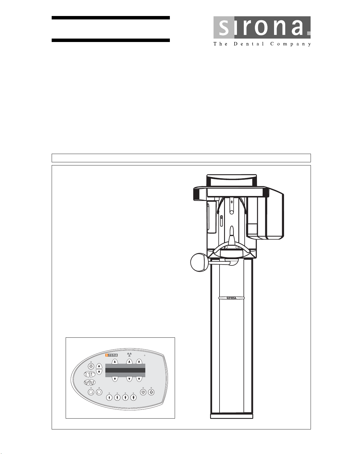
This document describes the installation of the ORTHO
PHOS XG XG3 panoramic X-ray unit.
kÉï=~ë=çÑW=
NMKOMNR
For installation, please refer also to the following docu
ments:
-
• Installation drawings
• "Installation Requirements" (separate document)
• Operating Instructions
•Service Manual
• Installation Report and Warranty Passport
• SIDEXIS XG, Digital Radiography:
Installation instructions
Our Customer Service Center can provide the technical
documentation in paper form free of charge on request pro
vided that the respective order numbers are specified cor
rectly.
The latest documentation can always be downloaded from
the Sirona homepage:
www.sirona.com/HOME/Service/Technical Documentation
-
-
-
Changes since the last version 07.2013:
Chapter or section page
6.2 Checking the device leakage current .................... 63
60 51 416 D 3352
D 3352.031.03.18.02
Page 3

Sirona Dental Systems GmbH
Installation Instructions ORTHOPHOS XG 3
Contents
1 Before you begin ............................................................................................................... 5
1.1 Identification of warnings ......................................................................... 6
1.2 Safety....................................................................................................... 7
1.3 System and sensor versions.................................................................... 8
1.4 Dimensions/Space requirements............................................................. 9
1.5 Mounting options ................................................................................... 10
1.6 Installation versions ............................................................................... 11
2 Delivery and transport .................................................................................................... 13
2.1 Delivery.................................................................................................. 14
2.2 Transport to the installation site............................................................. 18
3 Installation: Panoramic X-ray unit ................................................................................. 19
3.1 Installation material................................................................................ 20
3.2 Required tools........................................................................................ 22
3.3 Wall mounting (standard/option 1)......................................................... 23
3.4 Installing the floor stand (option 2)......................................................... 30
3.5 Removing the transport safety device ................................................... 40
3.6 Installing the release button holder........................................................ 41
3.7 Attaching the covers .............................................................................. 42
English
4 Electrical connection ...................................................................................................... 45
4.1 Connecting the control cables (PAN)..................................................... 46
4.2 Connecting the line voltage ................................................................... 47
5 Installation: Remote control........................................................................................... 49
5.1 Installation material/tools ....................................................................... 50
5.2 Mechanical installation........................................................................... 51
5.3 Connecting the control cables (REMOTE)............................................. 53
5.4 Connecting the door contact switch....................................................... 56
5.5 Connecting the X-ray warning lamp....................................................... 57
5.6 Final work .............................................................................................. 58
6 Safety checks................................................................................................................... 59
6.1 Checking the protective ground wires.................................................... 60
6.2 Checking the device leakage current..................................................... 63
7 Initial startup.................................................................................................................... 65
7.1 Inserting the forehead and temple supports .......................................... 66
7.2 Inserting the sensor ............................................................................... 67
7.3 Switching the units ON .......................................................................... 68
7.4 Checking the data paths ........................................................................ 69
60 51 416 D 3352
D 3352.031.03.18.02
Page 4

Sirona Dental Systems GmbH
Installation Instructions ORTHOPHOS XG 3
8 Startup for USA/Canada only ......................................................................................... 73
8.1 Startup, measurements and controls ..................................................... 74
8.2 Power supply adequacy ......................................................................... 75
8.3 Tube Current Verification ....................................................................... 76
8.4 kV – verification / Exposure Time Verification........................................ 79
8.5 Checking the laser for USA/Canada only............................................... 81
9 Checking the system adjustment .................................................................................. 83
9.1 Test exposures....................................................................................... 84
10 Final work......................................................................................................................... 91
10.1 Attaching the profile covers.................................................................... 92
10.2 Selecting More details............................................................................ 93
10.3 Declaration of Conformity....................................................................... 94
10.4 Unit handover......................................................................................... 95
11 Appendix .......................................................................................................................... 97
11.1 Service routines (for installation)............................................................ 98
11.2 Adjusting the panoramic X-ray unit ...................................................... 109
11.3 Demo mode.......................................................................................... 136
60 51 416 D 3352
D 3352.031.03.18.02
Page 5

ORTHOPHOS XG 3
1 Before you begin
60 51 416 D 3352
D 3352.031.03.18.02
5
Page 6
1 Before you begin Sirona Dental Systems GmbH
DANGER
WARNING
CAUTION
NOTICE
IMPORTANT
1.1 Identification of warnings Installation Instructions ORTHOPHOS XG 3
1.1 Identification of warnings
Warning and safety information
To prevent personal injury and material damage, please
observe the warning and safety information provided in the
present operating instructions.
The structure, appearance and use of warning and safety
information in Sirona documents are based on the ANSI
Z535 standard.
The following warnings may be used in this document:
An imminent danger that could result in serious bodily
injury or death.
A possibly dangerous situation that can result in seri
ous bodily injury or death.
A possibly dangerous situation that can result in slight bodi
ly injury.
A possibly harmful situation which can lead to damage of
the product or an object in its environment.
Instructions for use
The following application information may be used in this
document:
Application instructions and other important information.
Tip: Information on making work easier.
-
-
6 D 3352.031.03.18.02
60 51 416 D 3352
Page 7
Sirona Dental Systems GmbH 1 Before you begin
DANGER
WARNING
WARNING
WARNING
WARNING
CAUTION
NOTICE
NOTICE
NOTICE
Installation Instructions ORTHOPHOS XG 3 1.2 Safety
1.2 Safety
Fixed connection!
The installation of a power plug instead of the pre
scribed fixed (hard-wired) connection violates interna
tional medical regulations and is prohibited.
In case of a fault, you would thus endanger the life and
limb of the patient, the operator or other persons.
Installation and startup must be carried out in accor
dance with the requirements stated in our Installation
Instructions.
Installation and startup may be carried out only by per
sonnel specifically authorized by SIRONA.
Any person who assembles or modifies a medical elec
trical system complying with the standard IEC 60
601-1-1
(safety requirements for medical electrical equipment)
by combining it with other equipment is responsible for
ensuring that the requirements of this regulation are
met to their full extent for the safety of the patients, the
operators and the environment.
-
-
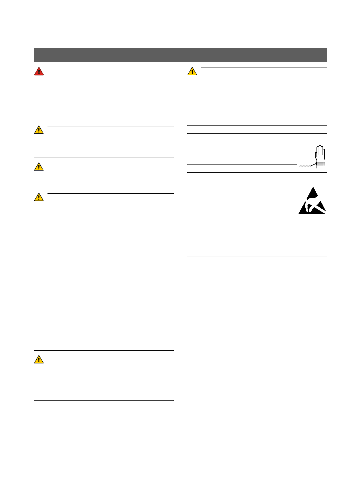
The unit contains class 1 lasers.
Keep a distance of at least 4" (10 cm) between eye and la
-
ser. Do not stare into the beam.
Do not use the system with any other lasers, and do not
make any changes to settings or processes that are not de
scribed in these operating instructions. This may lead to a
dangerous exposure to radiation.
Use an ESD wrist band during installation.
Connect it to the
protective ground wire.
-
When opening the unit:
Please observe the usual precautionary
measures for handling PCBs (ESD).
Touch a ground point to discharge static elec
-
tricity before handling any components.
Extreme fluctuations of temperature may cause condensa
tion inside the unit. Do not switch the unit on before it has
reached normal room temperature.
-
-
-
-
English
If any equipment not approved by SIRONA is connect
ed, it must comply with the applicable standards:
- IEC 60950-1 for information technology equipment
and
- IEC 60 601-1 for medical electrical equipment.
See also “On-site installation, dimensions, technical
data” and the “Compatibility list/Declaration of
conformity” issued by the system integrator.
In case of doubt, contact the manufacturer of the sys
tem components.
Wireless phone interference with medical electrical
equipment:
To ensure safe operation of medical electrical equip
ment, the use of mobile wireless phones in practice or
hospital environments is prohibited.
-
-
-
60 51 416 D 3352
D 3352.031.03.18.02
7
Page 8
1 Before you begin Sirona Dental Systems GmbH
1.
2.
1.3 System and sensor versions Installation Instructions ORTHOPHOS XG 3
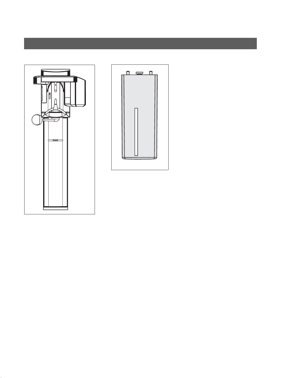
1.3 System and sensor versions
1. ORTHOPHOS XG 3
Digital unit
2. XG PAN sensor
Sensor for panoramic (PAN) X-ray
60 51 416 D 3352
8 D 3352.031.03.18.02
Page 9

Sirona Dental Systems GmbH 1 Before you begin
NOTICE
NOTICE
Installation Instructions ORTHOPHOS XG 3 1.4 Dimensions/Space requirements
1.4 Dimensions/Space requirements
English
The minimum ceiling height should be 2.10 m (82 11/16"). If
the ceiling height is lower than 2.27 m (89 3/8“) (max. travel
height of 2.25 m (88 1/2“)), the travel height of the unit must
be adjusted or limited prior to startup of the unit (see section
11.1.7). )
60 51 416 D 3352
D 3352.031.03.18.02
The dimensions specified here apply to installation of the
X-ray unit without the floor stand. Installation with the floor
stand results in an additional 30 mm (1 3/16“) increase of all
height dimensions.
9
Page 10
1 Before you begin Sirona Dental Systems GmbH
IMPORTANT
1. 3.2.
Standard version Option 1 Option 2
1.5 Mounting options Installation Instructions ORTHOPHOS XG 3
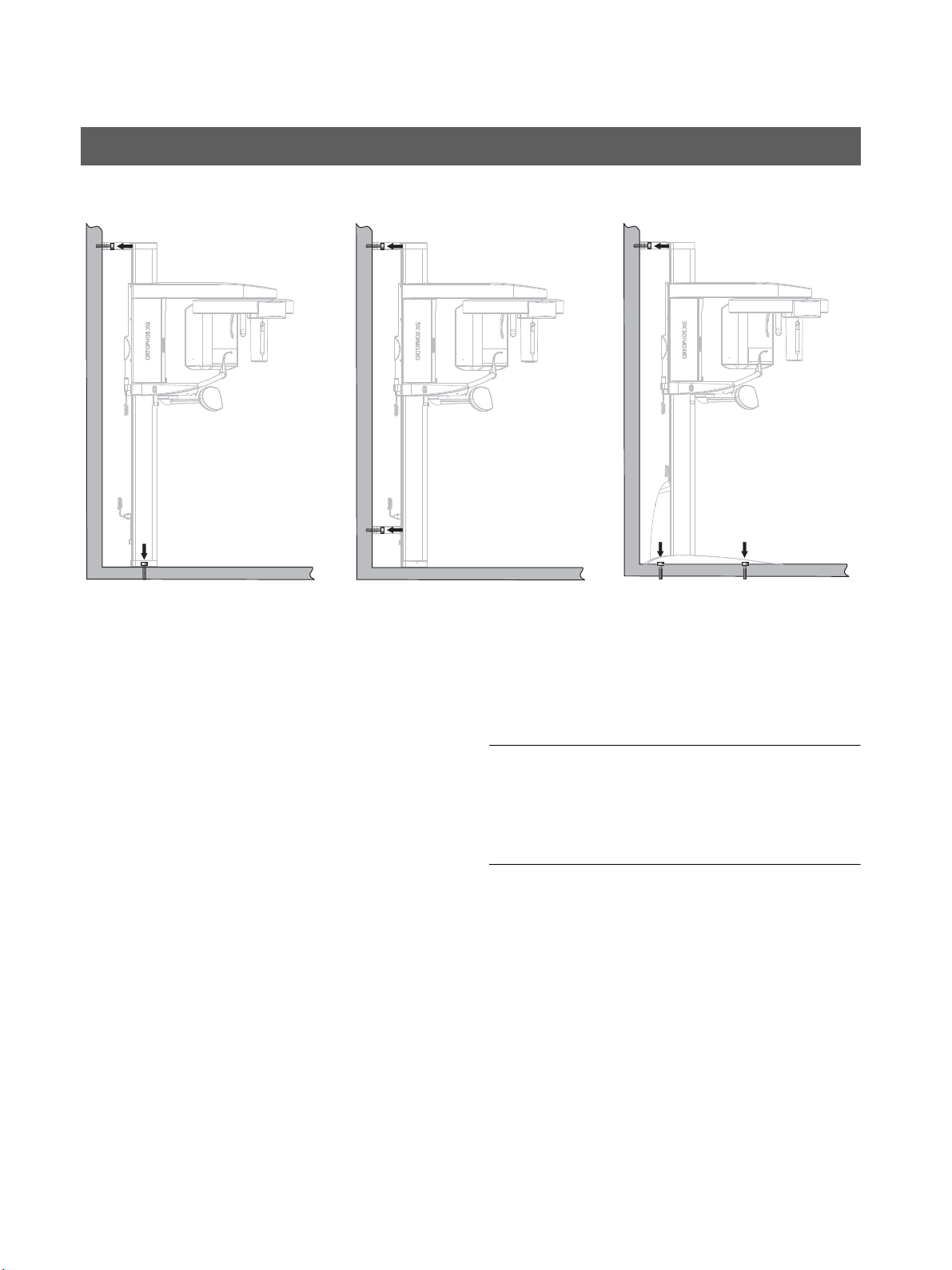
1.5 Mounting options
Standard version
(see Section 3.3)
1. Wall-mounted installation with 1 wall holder and
floor fastening if both wall and floor installation are
possible on-site.
Option 1: with second wall holder
(see Section 3.3)
2. Wall-mounted installation with 2 wall holders (and
no floor fastening) if only wall installation is possible
on-site.
Option 2: with floor stand
(see section 3.4)
3. Installation with floor stand for free installation any
where in the room or if wall-mounted installation is not
possible on-site (e.g. with lightweight walls).
If the unit is installed freely with a floor stand, the quality of
the resulting X-ray exposures may be impaired,
depending on the floor or surface conditions. Sirona there
fore recommends additional fastening of the unit with an up
per wall holder also when installing it with a floor stand.
-
-
-
10 D 3352.031.03.18.02
60 51 416 D 3352
Page 11
Sirona Dental Systems GmbH 1 Before you begin
1. 2.
3.
Installation Instructions ORTHOPHOS XG 3 1.6 Installation versions
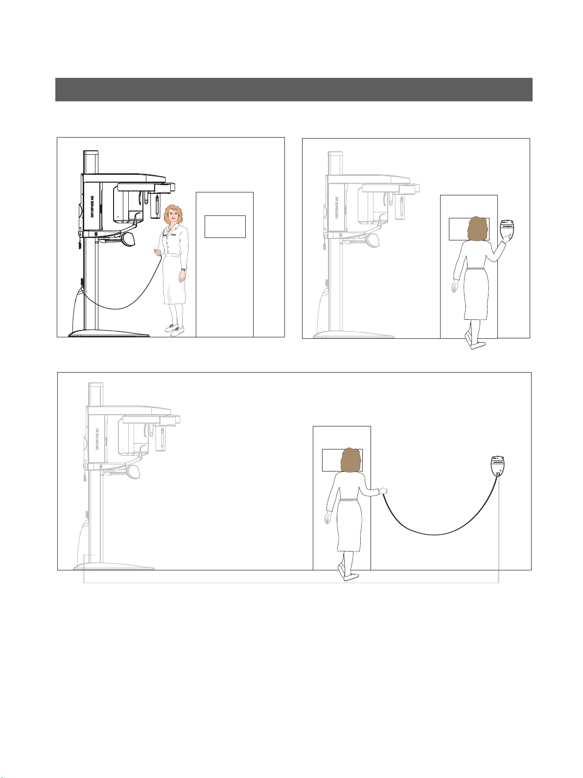
1.6 Installation versions
1. Standard installation:
ORTHOPHOS XG 3 without remote control with re
lease button on the coiled cable in the treatment
room.
2. Installation version 1 (see section 5.3.1):
-
ORTHOPHOS XG 3 with remote control outside the
X-ray room without release button on the coiled ca
ble.
English
-
60 51 416 D 3352
D 3352.031.03.18.02
3. Installation version 2 (see section 5.3.2):
ORTHOPHOS XG 3 with remote control outside the
X-ray room with release button on the coiled cable.
11
Page 12

1 Before you begin Sirona Dental Systems GmbH
1.6 Installation versions Installation Instructions ORTHOPHOS XG 3
12 D 3352.031.03.18.02
60 51 416 D 3352
Page 13

ORTHOPHOS XG 3
2 Delivery and transport
60 51 416 D 3352
D 3352.031.03.18.02
13
Page 14
2 Delivery and transport Sirona Dental Systems GmbH
NOTICE
IMPORTANT
IMPORTANT
Dimensions (cm): 199 x 69 x 122
Weight: 177 kg (390 lbs)
(inches): 78 3/8 x 30 3/4 x 28 3/4
2.1 Delivery Installation Instructions ORTHOPHOS XG 3
2.1 Delivery
Possible transport damage!
If the shipment was damaged during transport, document
all damage carefully and contact the responsible carrying
agent immediately.
All SIRONA equipment is carefully checked and packed
prior to shipment. Please carry out an incoming inspection
of the equipment in order to make sure that it was not dam
aged during transport.
• Check the packaging and the equipment for visible
signs of damage.
• Check the shipment for completeness based on the at
tached “scope of supply” checklist.
Disposal: Return the packaging materials to SIRONA or
dispose of them in compliance with the legal regulations ap
plicable in your country.
14 D 3352.031.03.18.02
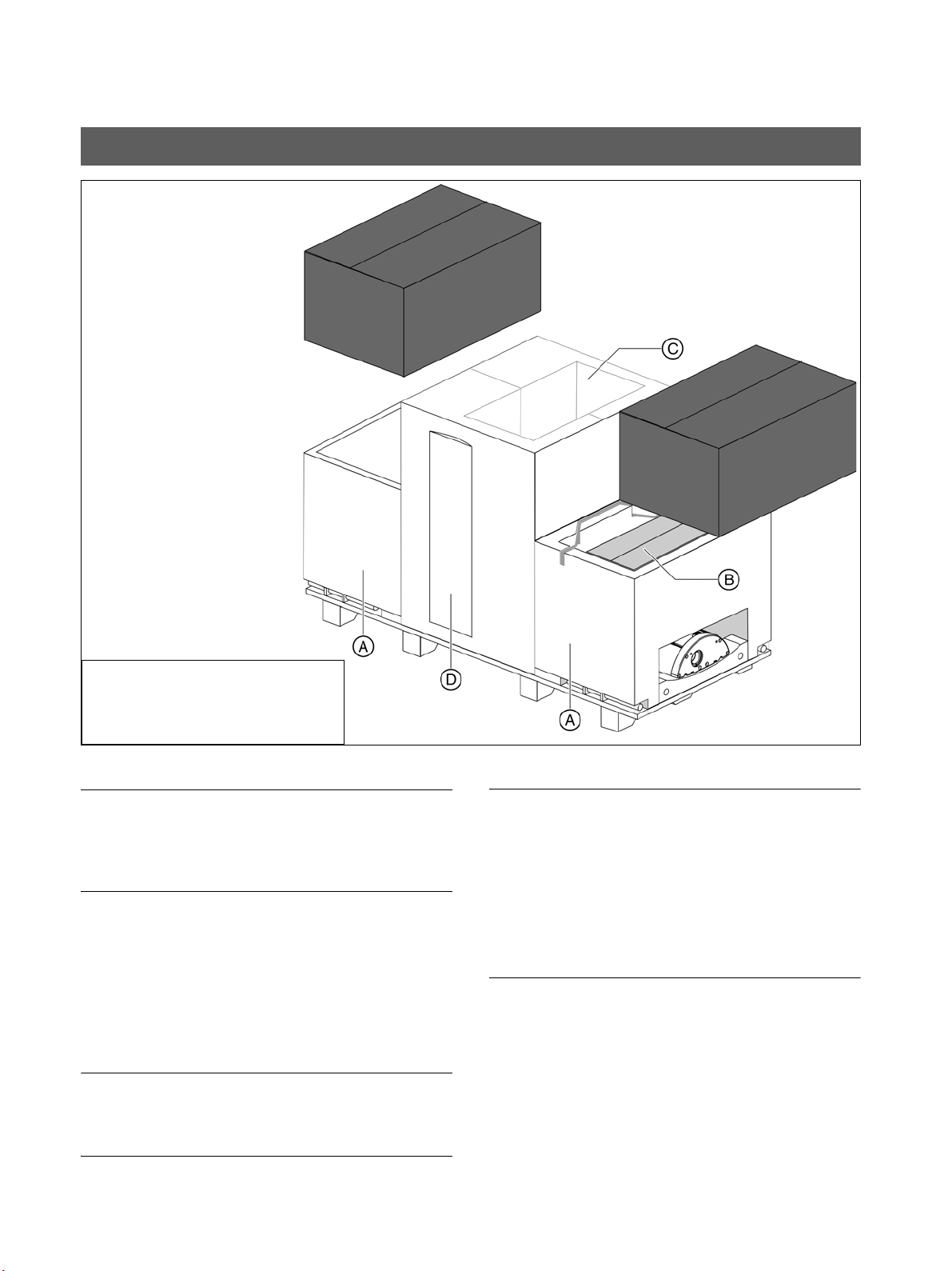
The packaging of the X-ray unit is designed both for protec
tion during transport and as an installation aid.
Therefore, please remove only the surrounding packaging
prior to installation. Please leave the styrofoam packaging
and transport pallet attached to the unit.
Save one of the lateral styrofoam packaging parts for
-
later use as an installation aid A.
Scope of supply
• Panoramic X-ray unit
-
• Profile cover (D)
•Sensor (B)
• Accessories and hygienic protective covers (see pp.
16 ff.) (B)
• Installation material (see section 3.1) (B)
-
• Safety strap (B)
• Remote control (optional) (C)
60 51 416 D 3352
-
Page 15
Sirona Dental Systems GmbH 2 Delivery and transport
A
A
B
Installation Instructions ORTHOPHOS XG 3 2.1 Delivery
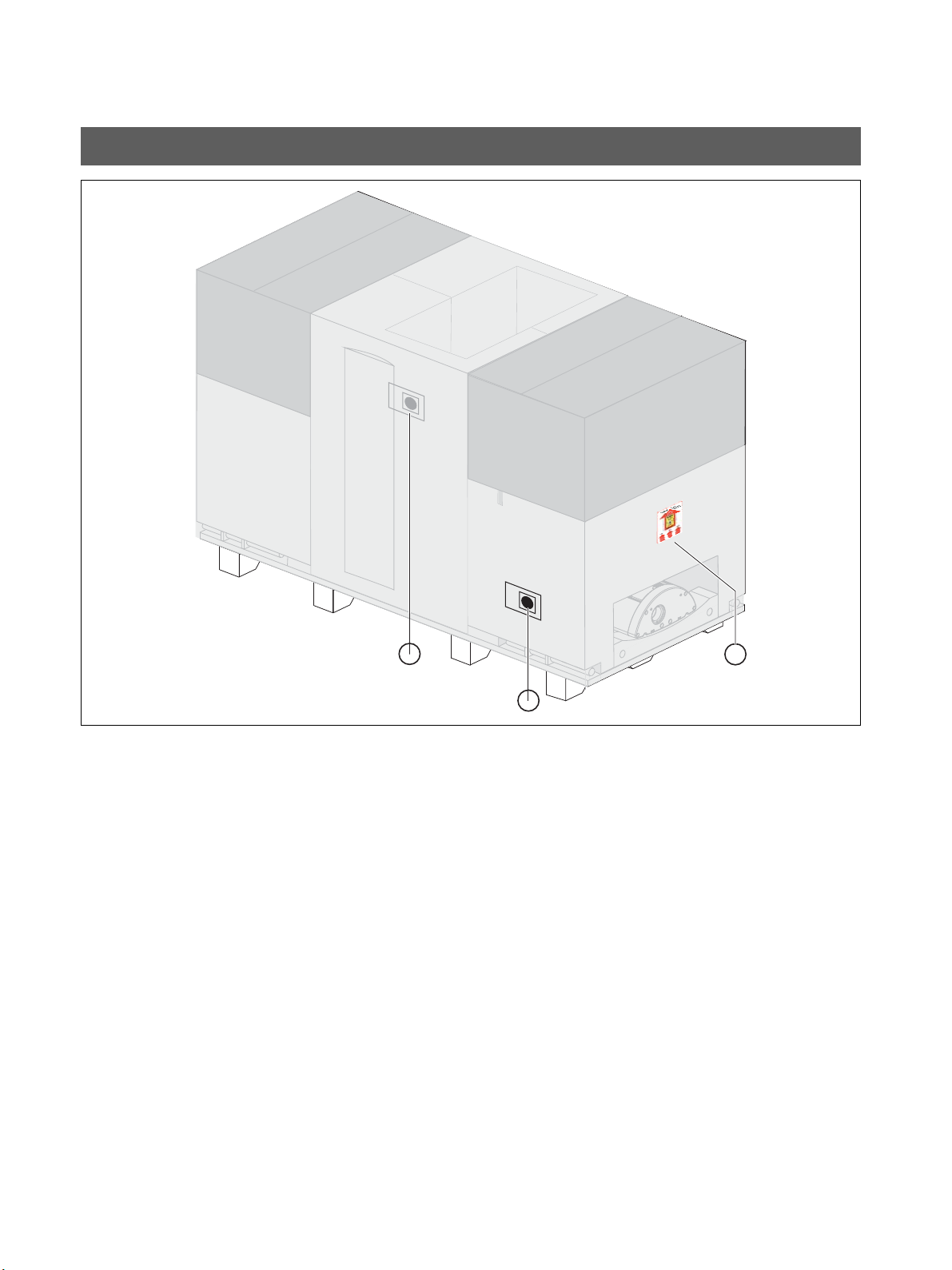
Tw o shock indicators A are attached to the side of the
packaging to indicate whether the unit was exposed to a
shock during transport.
• White indicator: No shock
• Red indicator: Shock
A tilt indicator B that enables you to recognize whether the
unit was transported improperly is also attached to the
packaging.
• Red indicator: Improper transport
The display of improper transport doesn't necessarily mean
that the unit is damaged.
Make a note on the delivery slip that the indicator is acti
-
vated. Have this confirmed on the delivery note by the driver
of the transport company.
Fax the delivery slip to the Sirona Customer Service Center
(CSC).
Enter the state of the indicators in the startup report in the
case of warranty claims.
60 51 416 D 3352
D 3352.031.03.18.02
15
Page 16
2 Delivery and transport Sirona Dental Systems GmbH
8.
12.
10.
11.
13.
7.
9.
Bar
Bite block
Bite block fixation
14.
Chin rest
Chin pad
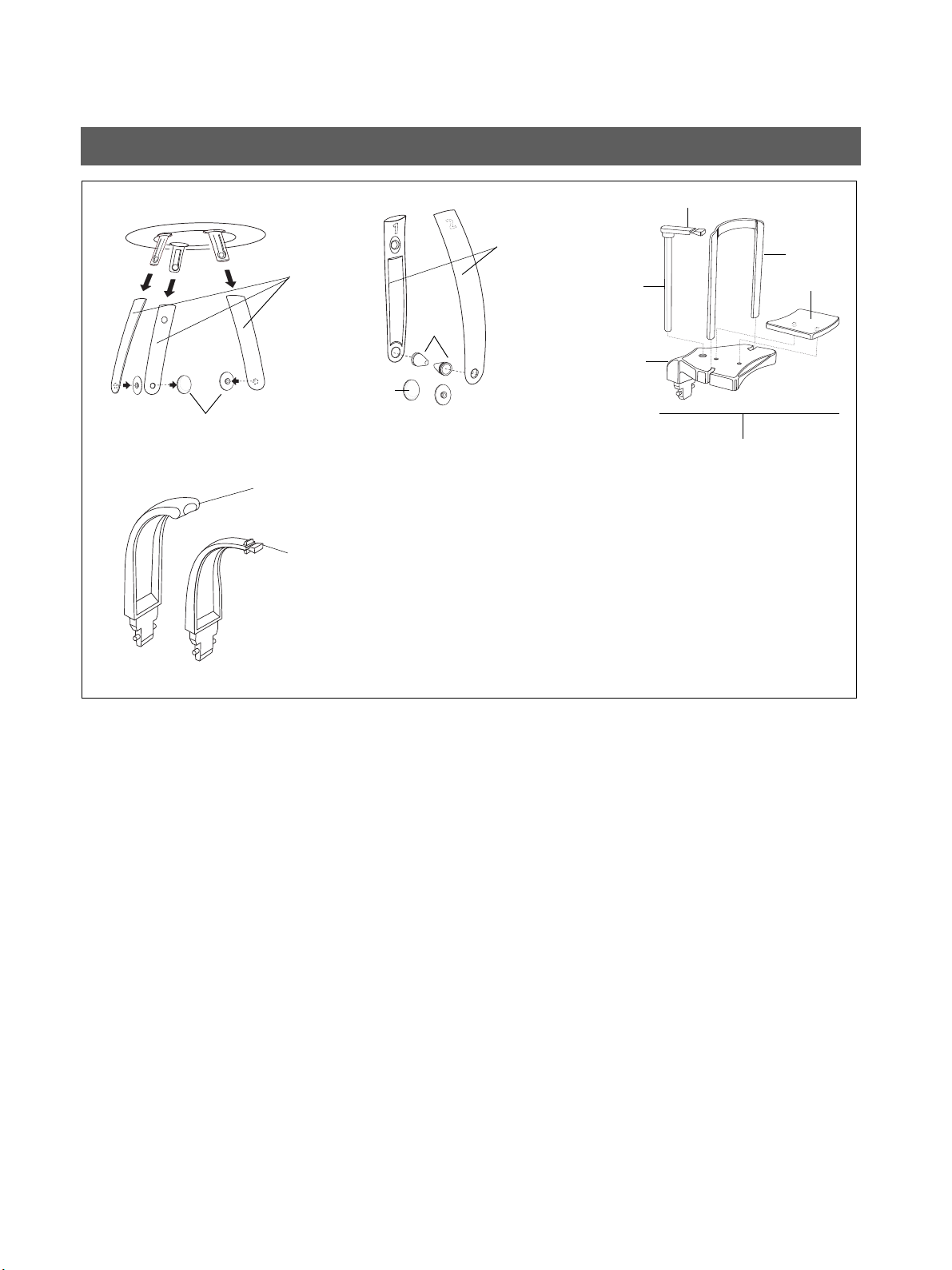
2.1 Delivery Installation Instructions ORTHOPHOS XG 3
Accessories: Panoramic X-ray unit
1. Forehead (1x) and temple supports (2x)
2. Buttons (2x)
3. Temporomandibular joint supports 1 (1x) and 2 (1x)
4. Ear holders (4x)
5. Buttons TMJ (2x)
6. Chin rest accessories (1x)
– Bite block (5x)
– Bite block fixation (1x)
–Bar (1x)
– Chin pad (1x)
– Chin rest (1x)
7. Contact segment standard yellow (1x)
8. Bite block standard yellow (1x)
16 D 3352.031.03.18.02
60 51 416 D 3352
Page 17
Sirona Dental Systems GmbH 2 Delivery and transport
19.
18.
17.
20.
21.
22.
23.
Top sideBottom side
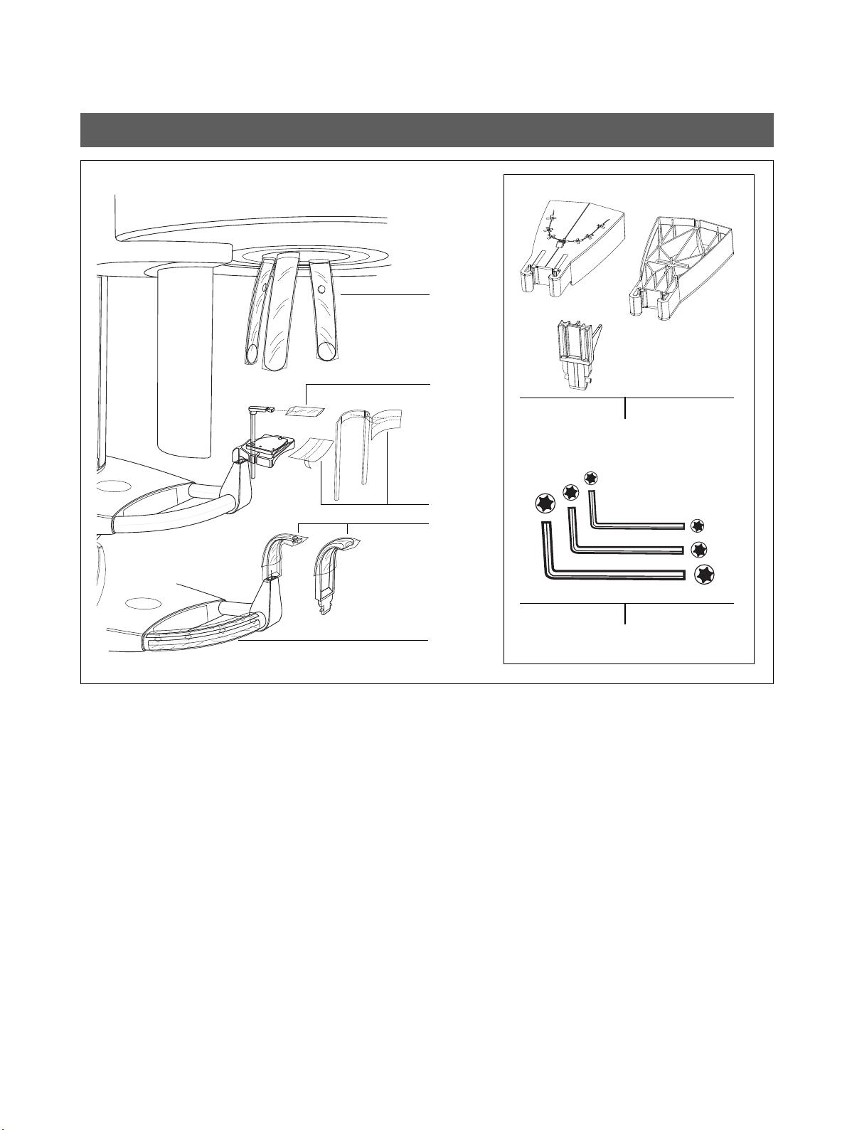
Installation Instructions ORTHOPHOS XG 3 2.1 Delivery
Hygienic protection
Hygienic protective sleeves for...
9. Forehead and temple supports (500x)
10. Bite block (500x)
11. Chin rest and bar (100x)
12. Bite blocks and contact segments (500x)
13. XG hygienic handle (100x)
Adjustment set: Panoramic X-ray unit
14. Panoramic needle phantom
15. Set of Torx offset screwdrivers
60 51 416 D 3352
D 3352.031.03.18.02
17
Page 18
2 Delivery and transport Sirona Dental Systems GmbH
NOTICE
WARNING
IMPORTANT
NOTICE
IMPORTANT
1. 2.
A
B
short
long
C
D
D
E
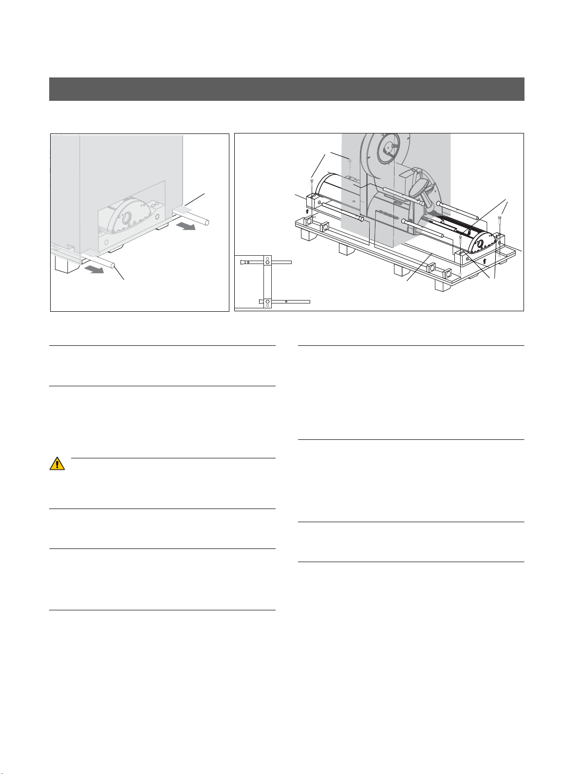
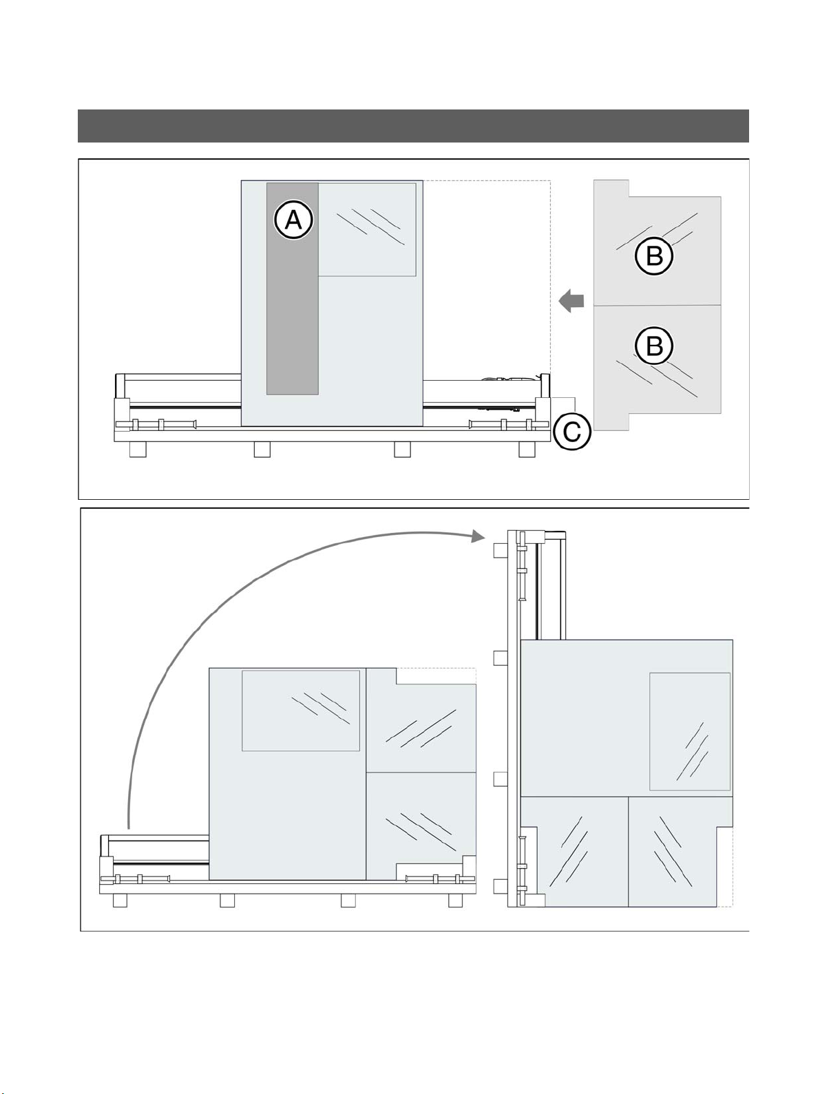
2.2 Transport to the installation site Installation Instructions ORTHOPHOS XG 3
2.2 Transport to the installation site
If possible leave the packaging attached to the unit during
transport in order to protect it against damage.
1. Transport with packaging attached (normal case)
– Open the surrounding packaging at the tabs pro
vided for that purpose (A), pull out the carrying
handles (B), and transport the unit to the installa
tion site.
When in transport position, the unit has a very high
center of gravity. Take care that the unit does not tip
over during transport.
2. Transport without pallet (exception)
If the pallet is too wide for transport to the installation site,
you may unscrew the pallet from wooden support C and
transport the unit by means of the wooden supports without
the pallet.
To do this, proceed as follows:
– Remove the surrounding packaging, the two card
board boxes, as well as the two lateral styrofoam
parts.
– Loosen the four screws D.
The center styrofoam part should remain attached to the
unit for protection. If this is not possible, SIRONA recom
mends securing the tube assembly in its position with the
supplied strap prior to any further transport
-
-
-
(see the label on the styrofoam packaging)!
Tighten the strap only loosely. Do not stretch!
– Pull the carrying handles B out of their holders and
insert them through the drillings of the wooden sup
port C from the back.
– Insert screws D through the drillings E into the drill
ings of the carrying handles to attach them firmly.
Long or short.
The carrying handles have rims which prevent them from
slipping out of the holes.
-
-
-
18 D 3352.031.03.18.02
60 51 416 D 3352
Page 19

3 Installation: Panoramic X-ray unit
ORTHOPHOS XG 3
60 51 416 D 3352
D 3352.031.03.18.02
19
Page 20
3 Installation: Panoramic X-ray unit Sirona Dental Systems GmbH
1. 2.
for installation
on wooden stud
frame
for installation
on wooden stud
frame
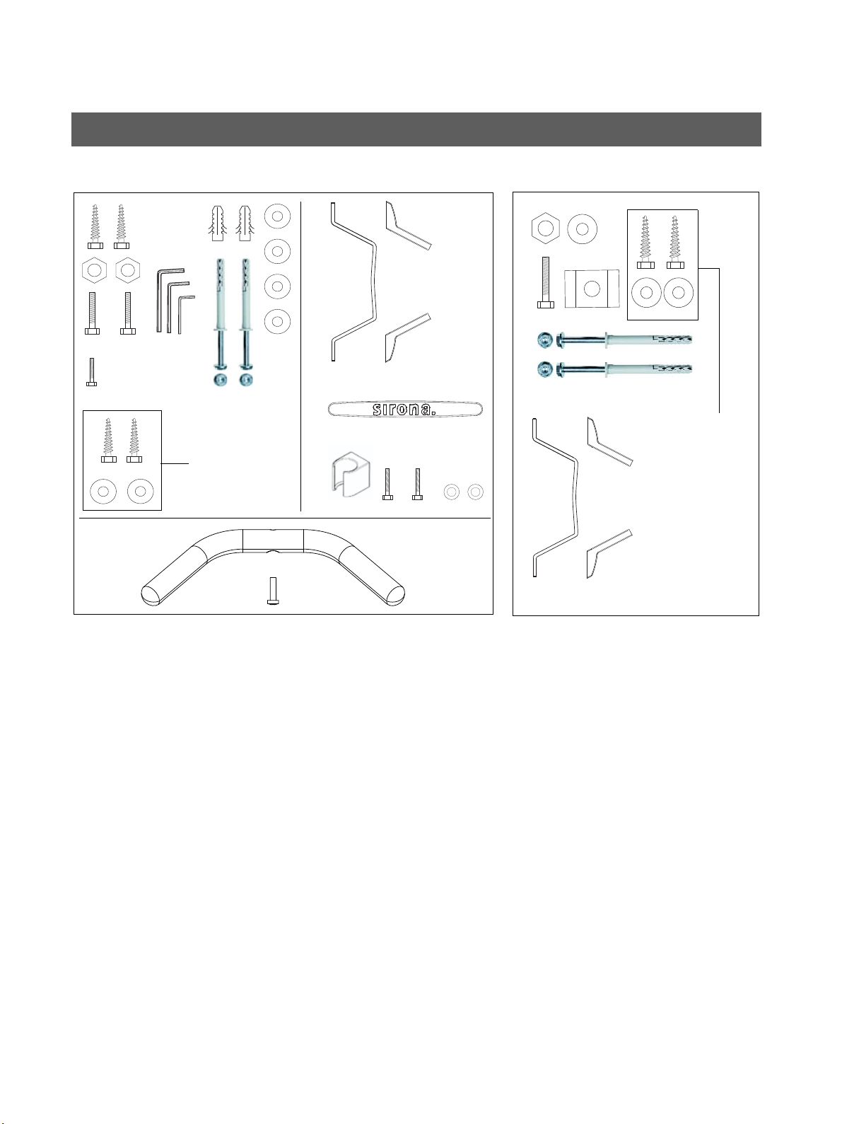
3.1 Installation material Installation Instructions ORTHOPHOS XG 3
3.1 Installation material
Standard version
(see Section 3.3)
Option 1: with second wall holder
(see Section 3.3)
1. Wall/floor mounting
– Hexagon wood screws 8x80 (5/16x3"): 4 pc.
– Plastic wall plug S10: 2 pc.
– Screw M8x30: 2 pc.
–Washer δια. 8.4: 6 pc.
– Nut M8: 2 pc.
– Screw M4x10: 3 pc.
–Washer δια. 4.3: 2 pc.
– Mounting kit δια. 10 SXR: 2 pc.
– Torx offset screwdrivers TX10, TX20, TX25: resp. 1
pc.
– Offset Allen key (size 6):
1 pc.
– Wall holder: 1 pc.
– Cover for wall holder: 2 pc.
– Intermediate piece: 1 pc.
– Release button holder: 1 pc.
– Handle: 1 pc.
– Screw (for handle) M6x25: 1 pc.
2. Additional wall holder (for bottom wall mounting)
– Wall holder: 1 pc.
– Wood screws 8x80 (5/16x3"): 2 pc.
–Washer δια. 8.4: 3 pc.
– Hexagon head screw M8x50: 1 pc.
– Nut M8: 1 pc.
– Mounting kit δια. 10 SXR: 2 pc.
– Profile clamp: 1 pc.
– Cover for wall holder: 2 pc.
20 D 3352.031.03.18.02
60 51 416 D 3352
Page 21

Sirona Dental Systems GmbH 3 Installation: Panoramic X-ray unit
3.
Option 2
Mounting hardware
Floor stand
Covers
Floor stand
Cover
Slide
Installation Instructions ORTHOPHOS XG 3 3.1 Installation material
Option 2: Floor stand installation
(see Section 3.4)
3. Floor stand installation
– Floor stand
– Floor stand covers
– Wood screws 10x160 (3/8x6"): 5 pc.
– Plastic wall plug S12: 5 pc.
– Screw EM8x60: 2 pc.
– Screw M8x80: 2 pc.
– Washer δια. 8.4: 2 pc.
– Nut M8: 2 pc.
– Screw M10x50: 1 pc.
– Profile clamp: 1 pc.
– Screw M5x12: 1 pc.
– Washer δια. 10.5: 13 pc.
– Nut M10: 4 pc.
– Spring steel clamp: 8 pc.
– Screw M10x25: 4 pc.
– Wood screw M10x80 (3/8x3): 5 pc.
– Mounting kit δια. 10 SXR: 2 pc.
60 51 416 D 3352
D 3352.031.03.18.02
21
Page 22
3 Installation: Panoramic X-ray unit Sirona Dental Systems GmbH
1.
2.
3.
7.4.
5.
6.
8.
9.
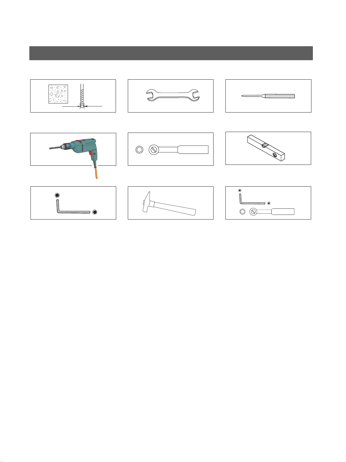
3.2 Required tools Installation Instructions ORTHOPHOS XG 3
3.2 Required tools
1. Masonry drill
– Δια.10mm (3/8“)
2. Impact drill or percussion drill
3. Torx offset screwdriver *
–TX10
–TX20
–TX25
4. Open-end wrench
– 13 mm A/F
5. Socket wrench
– Wrench insert 13
6. Hammer
7. Center punch
8. Spirit level
9. Additional requirements for installation with floor stand:
– Masonry drill δια.12mm (1/2“)
– Allen key 6 mm
– Socket wrench and extension
Wrench insert 17
Required measuring instruments
• Multimeter or ammeter (battery-operated)
• Test unit for device leakage current measurement,
e.g. Bender tester or line-frequency, high-resistance
measurement voltage source (isolation transformer)
and measuring circuit (MD) that meets the require
ments of IEC 60 601-1.
• Power source for protective ground wire test
Technical data:
– No-load voltage of at least 4 V - maximally 24V
– Short-circuit current at least 0.2A
-
* included in the scope of supply
22 D 3352.031.03.18.02
60 51 416 D 3352
Page 23
1.
2.
Sirona Dental Systems GmbH 3 Installation: Panoramic X-ray unit
Installation Instructions ORTHOPHOS XG 3 3.3 Wall mounting (standard/option 1)
3.3 Wall mounting (standard/option 1)
60 51 416 D 3352
D 3352.031.03.18.02
23
Page 24
3 Installation: Panoramic X-ray unit Sirona Dental Systems GmbH
IMPORTANT
CAUTION
IMPORTANT
3.
B
C
D
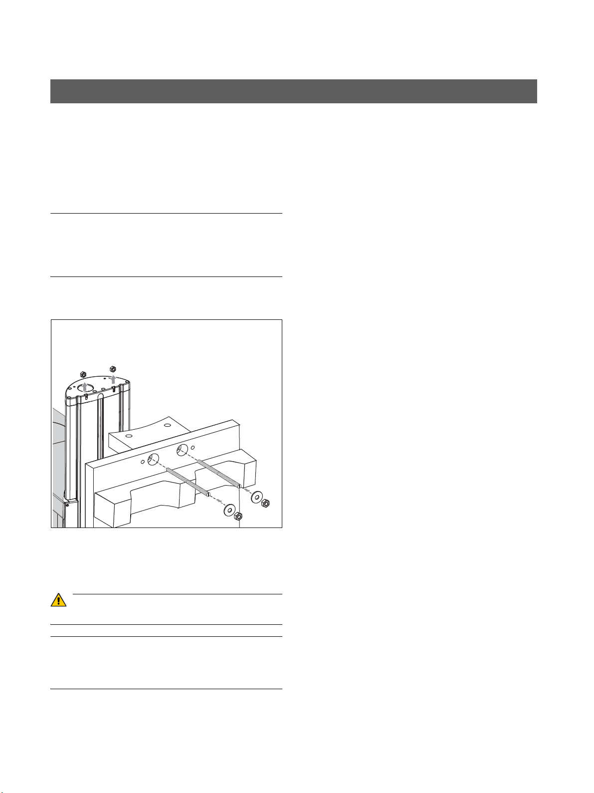
3.3 Wall mounting (standard/option 1) Installation Instructions ORTHOPHOS XG 3
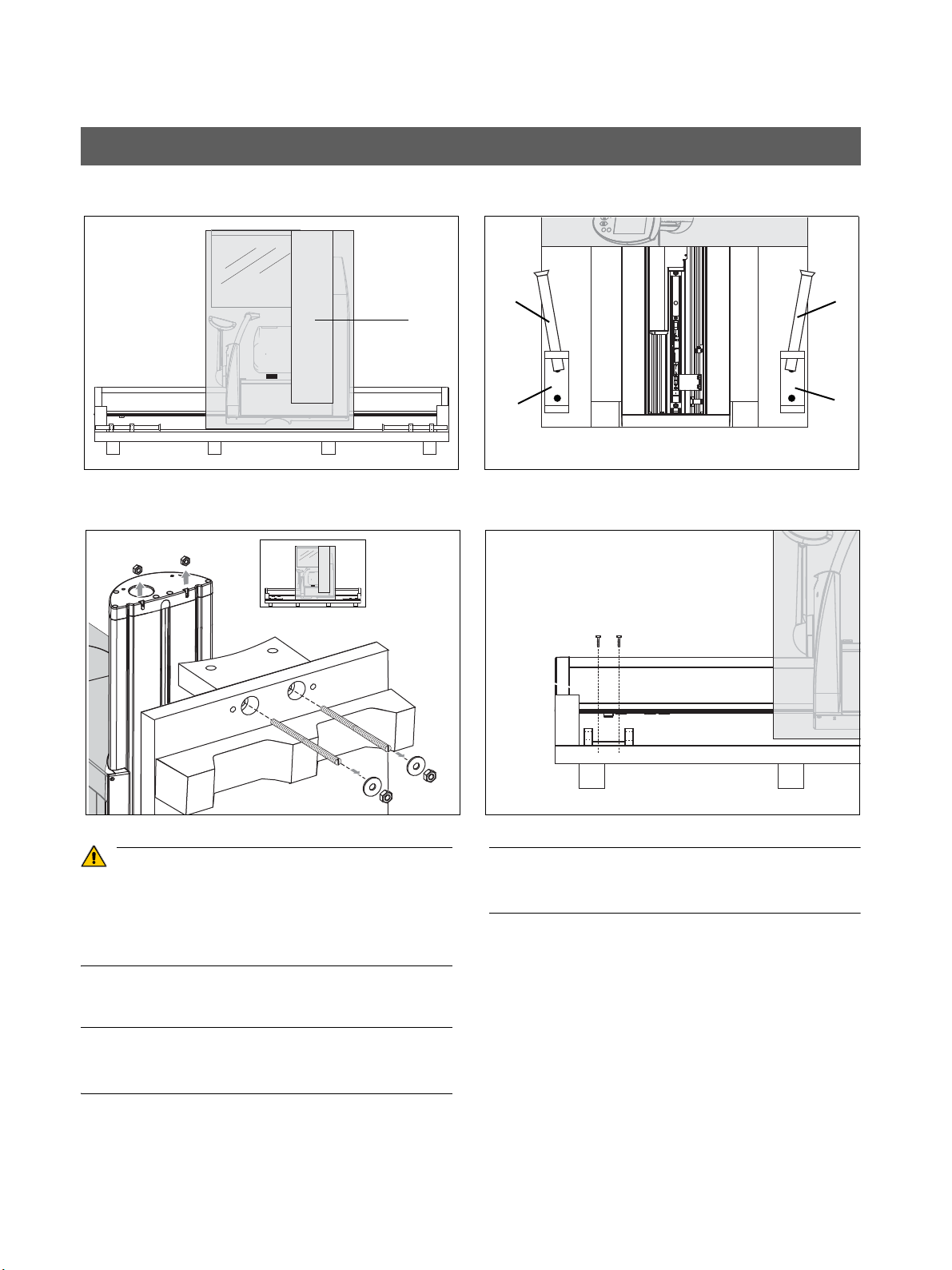
• Remove profile cover A.
1. Position the two installation aids B at the foot C of the
device and secure their position with adhesive tape.
CAUTION! The installation aids must be placed on
top of each other in such a way that their openings
lie on top of each other
2. Set up the unit. To do this, tilt the transport pallet up
right.
-
If you have transported the unit on the wooden support with
out a pallet, set the unit upright with the wooden support.
You can also use the lateral styrofoam packaging as a sup
port with this variation.
-
-
3. Loosen the nuts B (with washers) on both sides of the
Remove the lower bolts first, followed by the upper bolts.
The nuts D on the unit may remain inside the unit when the
threaded rods are removed. Remove the upper nuts. The
lower nuts may remain in the unit.
24 D 3352.031.03.18.02
pallet (or the wooden support). Take off the pallet (or
the wooden support).
Remove the threaded bolts C.
60 51 416 D 3352
Page 25
Sirona Dental Systems GmbH 3 Installation: Panoramic X-ray unit
CAUTION
2x 8x80
2x δια. 8.4
4.
Δια. 3/8″
Δια.
10 mm
Installation Instructions ORTHOPHOS XG 3 3.3 Wall mounting (standard/option 1)
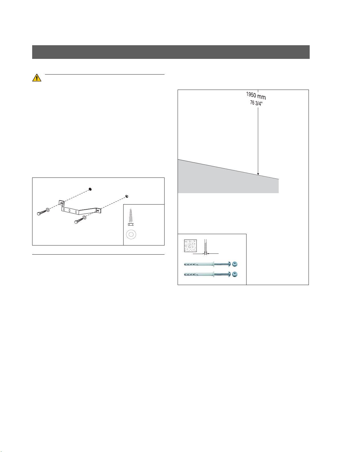
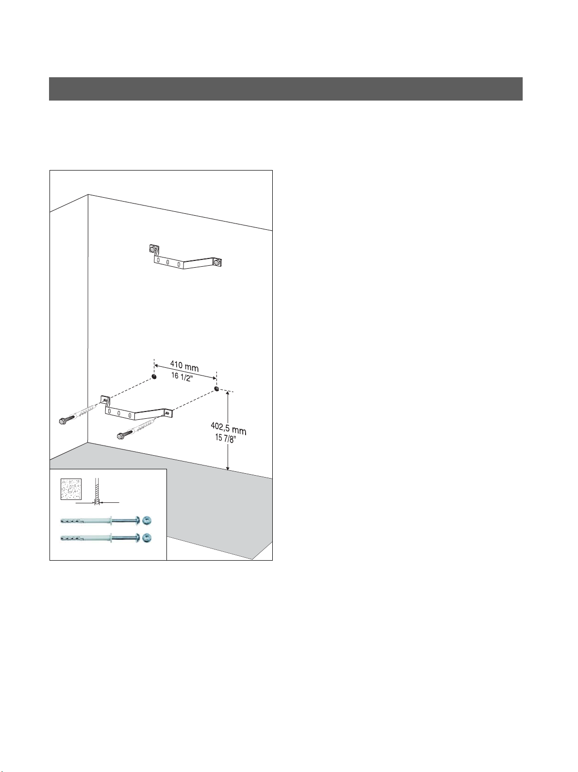
4. Mount the upper wall holder.
If the setup site for the unit is carpeted, the carpeting must
be removed.
Wall plugs! Each wall plug must withstand an extraction
force of 700 N.
The wall construction must be suitable for installation of the
unit (see "On-site installation, dimensions, technical data")
In case of mounting on weight-bearing wooden con
structions:
Use the enclosed wood screws and washers from the
mounting kit for mounting the unit on weight-bearing wood
structures.
-
60 51 416 D 3352
D 3352.031.03.18.02
25
Page 26
3 Installation: Panoramic X-ray unit Sirona Dental Systems GmbH
5.
Δια. 3/8″
Δια.
10 mm
3.3 Wall mounting (standard/option 1) Installation Instructions ORTHOPHOS XG 3
Only with second wall holder (option 1):
5. Mount the lower wall holder.
26 D 3352.031.03.18.02
60 51 416 D 3352
Page 27
Sirona Dental Systems GmbH 3 Installation: Panoramic X-ray unit
NOTICE
IMPORTANT
6.
E
F
2x M 8x30
2x δια. 8.4
2x M 8
7.
1x M 8x50
1x δια. 8.4
G
H
E
F
G
H
8.
D
1x M 8
J
Profile clamp
1x
K
K
J
Installation Instructions ORTHOPHOS XG 3 3.3 Wall mounting (standard/option 1)
• Move the panoramic X-ray unit into its installation posi
tion at the wall. Hold the unit laterally at the styrofoam
packaging to do this.
SIRONA recommends leaving the styrofoam packaging on
the unit during the entire installation procedure!
If due to on-site conditions it is unavoidable to remove the
styrofoam packaging already at this point, you may move
the unit by carefully grasping the bite block bar and the
stand.
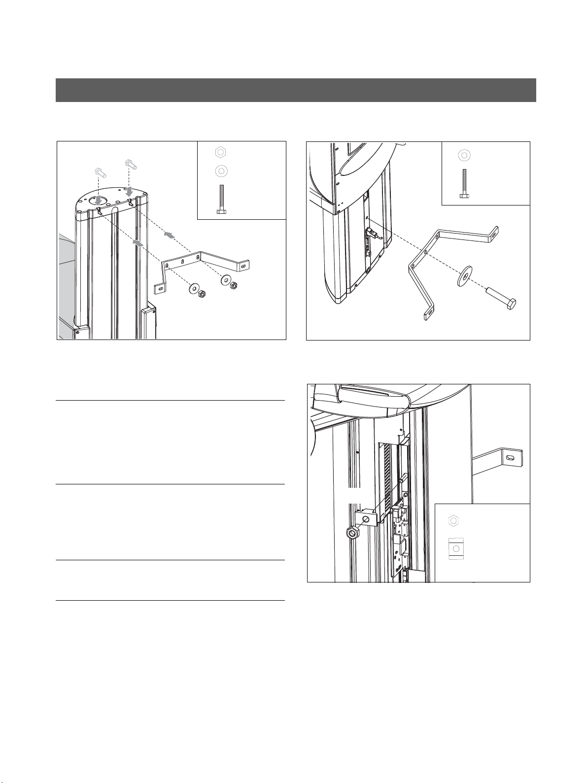
6. Fasten the panoramic X-ray unit to the upper wall hold
er.
– Insert the screws E into the groove.
– Screw the panoramic X-ray unit firmly onto the wall
holder using the washers and nuts F.
The wall holder must be flush with the upper edge of the
unit.
-
-
7. Insert screw G through washer H and then through
the wall holder and into the stand from the rear.
8. Fit profile clamp J onto screw G from the other (front)
side and screw nut K onto the screw.
Tighten nut K firmly.
60 51 416 D 3352
D 3352.031.03.18.02
27
Page 28
3 Installation: Panoramic X-ray unit Sirona Dental Systems GmbH
12.
➊
➋
9. 10.
L
A
3.3 Wall mounting (standard/option 1) Installation Instructions ORTHOPHOS XG 3
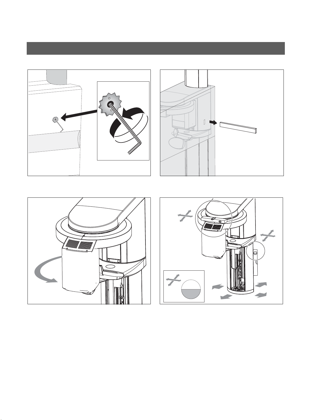
9. Remove the transport safety device (A) prior to unit
startup.
10. Pull the wooden board L out of the styrofoam packag
ing and remove all styrofoam packaging.
11. Rotate the X-ray tube assembly counterclockwise to
the front side of the unit.
12. Level the unit by moving the unit base in both directions
while measuring with the spirit level.
-
– Align the stand first by placing the spirit level
against the side and rear of the stand
– Then align the ring with the spirit level in both
directions by placing the spirit level on the ring
➊ .
➋ .
28 D 3352.031.03.18.02
60 51 416 D 3352
Page 29
Sirona Dental Systems GmbH 3 Installation: Panoramic X-ray unit
14.
2x S 10
Δια. 10 mm
2x 8x80
2x δια. 8.4
N
M
N
O
M
O
13.
Installation Instructions ORTHOPHOS XG 3 3.3 Wall mounting (standard/option 1)
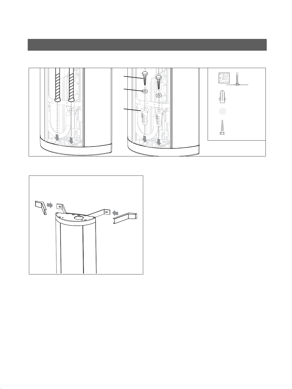
13. Drill through the recesses of the stand into the floor. In
sert wall plug M, and check again that the stand is
aligned correctly (see step 10).
Screw the stand to the floor with the two wood screws N
and the washers O.
14. Attach the covers of the wall holder(s).
-
60 51 416 D 3352
D 3352.031.03.18.02
29
Page 30
3 Installation: Panoramic X-ray unit Sirona Dental Systems GmbH
CAUTION
NOTICE
IMPORTANT
1.
A
B
C
C
B
C
D
2. 4.
E
G
F
Must be dis
-
mantled ly
-
ing on its
3.
E
F
F
3.4 Installing the floor stand (option 2) Installation Instructions ORTHOPHOS XG 3
3.4 Installing the floor stand (option 2)
For installation with the floor stand, the unit remains lying on
the pallet until the floor stand has been completely assem
bled. Only then may the unit be installed. For enhanced rep
resentation, some of the following drawings are shown in
the standing state.
1. Remove the surrounding packaging, the two lateral sty
rofoam parts and profile cover A.
The center styrofoam part should remain attached to the
unit for protection.
The nuts D on the unit may remain inside the unit when the
-
threaded rods are removed. Remove the nuts.
-
3. Remove the carrying handles E on the lower side of the
pallet from the holders F.
4. Loosen screws G and remove the holders F.
-
2. Loosen the nuts B (with washers) on both sides of the
30 D 3352.031.03.18.02
pallet (or the wooden support). Take off the pallet (or
the wooden support). Remove the threaded bolt C.
60 51 416 D 3352
Page 31

Sirona Dental Systems GmbH 3 Installation: Panoramic X-ray unit
NOTICE
5.
H
6.
JJ
H
Installation Instructions ORTHOPHOS XG 3 3.4 Installing the floor stand (option 2)
5. Carefully push the unit toward the base just far enough
so that the center styrofoam part nudges lower
supporting block H.
Make absolutely sure that the interfaces do not have firm
contact with supporting block H and are not damaged when
you push the unit.
6. Remove the two screws J from the bottom of the stand.
60 51 416 D 3352
D 3352.031.03.18.02
31
Page 32

IMPORTANT
7.
J
K
M
M
2x M 8x80
2x M8
2x EM 8 x 60
L
L
2x δια. 8.4
K
M
J
8.
N
O
4x δια. 10.5
4x M 10x25
P
M
J
L
O
3 Installation: Panoramic X-ray unit Sirona Dental Systems GmbH
3.4 Installing the floor stand (option 2) Installation Instructions ORTHOPHOS XG 3
7. Screw adjustment plate (K) onto the stand firmly.
To do this, use screws J for the two front holes and secure
them with the corresponding nuts L and washers (from the
installation material). Use two new screws M for the rear
holes.
The recessed drill holes of the adjustment plate must point
downward.
8. Screw the support N firmly onto the base plate P using
the 4 screws O and washers.
32 D 3352.031.03.18.02
60 51 416 D 3352
Page 33

NOTICE
9.
Q
3x δια. 10.5
3x M 10
Q
Q
Sirona Dental Systems GmbH 3 Installation: Panoramic X-ray unit
Installation Instructions ORTHOPHOS XG 3 3.4 Installing the floor stand (option 2)
9. Position the base plate with the threaded bolts (includ
ing the mounted support) on the adjustment plate and
attach the base plate loosely with the 3 adjustment
nuts Q (and washers).
-
Make sure that the cables are fed through the support cor
rectly and are not crushed.
60 51 416 D 3352
D 3352.031.03.18.02
-
33
Page 34

3 Installation: Panoramic X-ray unit Sirona Dental Systems GmbH
10. + 11.
U
R
1x M 10x50
1x δια. 10.5
S
S
R
U
T
1x M 10
Profile clamp
1x
T
R
S
U
T
3.4 Installing the floor stand (option 2) Installation Instructions ORTHOPHOS XG 3
10. Insert screw R through washer S and then through the
support and into the stand from behind.
11. Fit profile clamp T onto screw R from the other (front)
side and screw nut U onto screw R.
• Tighten adjusting nuts Q (see page 33) and screw R
firmly.
34 D 3352.031.03.18.02
60 51 416 D 3352
Page 35

Sirona Dental Systems GmbH 3 Installation: Panoramic X-ray unit
IMPORTANT
12.
Installation Instructions ORTHOPHOS XG 3 3.4 Installing the floor stand (option 2)
• Set up the unit including the center styrofoam part.
Please observe the required movement range of the X-ray
unit during installation (see section 1.6).
12. Remove the styrofoam packaging and rotate the X-ray
tube assembly counterclockwise to the front side of the
unit.
60 51 416 D 3352
D 3352.031.03.18.02
35
Page 36

3 Installation: Panoramic X-ray unit Sirona Dental Systems GmbH
IMPORTANT
13.
Q
Q
Q
➋
➊
14.
R
3.4 Installing the floor stand (option 2) Installation Instructions ORTHOPHOS XG 3
• Loosen screw R and adjusting nuts Q again slightly.
13. Level the unit in both directions by turning adjusting
nuts Q while measuring with the spirit level.
– Align the stand first by placing the spirit level
against the side and rear of the stand ➊ .
– Then align the ring with the spirit levelin both
directions ➋ by placing the spirit level on the ring.
Be sure to tighten all adjusting nuts equally (to the same
torque) after leveling.
14. Tighten screws R again firmly.
36 D 3352.031.03.18.02
60 51 416 D 3352
Page 37

Sirona Dental Systems GmbH 3 Installation: Panoramic X-ray unit
CAUTION
IMPORTANT
2x 8x80
2x δια. 8.4
15.
Δια. 3/8″
Δια.
10 mm
IMPORTANT
The floor stand version is
30 mm (1 3/16“) higher than
the standard version.
Installation Instructions ORTHOPHOS XG 3 3.4 Installing the floor stand (option 2)
15. Mount the upper wall holder.
In case of mounting on weight-bearing wood struc
tures:
Use the enclosed wood screws and washers from the
mounting kit for mounting the unit on weight-bearing wood
structures.
Even when the unit is installed using the floor stand it must
be secured with the upper wall holder.
-
60 51 416 D 3352
D 3352.031.03.18.02
37
Page 38

3 Installation: Panoramic X-ray unit Sirona Dental Systems GmbH
NOTICE
16.
2x M8x30
2x δια. 8.4
2x M8
V
W
V
W
3.4 Installing the floor stand (option 2) Installation Instructions ORTHOPHOS XG 3
• Slide the unit with the assembled floor stand up to the
wall.
Please observe the required movement range of the unit
during positioning (see section 1.2).
16. Mount the unit loosely on the upper wall holder.
– Insert the screws V into the groove.
– Screw the unit onto the wall holder loosely using
nuts W (and washers). Do not tighten the screws!
60 51 416 D 3352
38 D 3352.031.03.18.02
Page 39

Sirona Dental Systems GmbH 3 Installation: Panoramic X-ray unit
17.
X
Y
5x S12
5x 10 x 160
X
Y
Δια. 1/2″
Δια.
12 mm
Installation Instructions ORTHOPHOS XG 3 3.4 Installing the floor stand (option 2)
• Level the unit again in both directions with the help of
the spirit level (see step 12.) and tighten the screws on
the wall holder firmly.
17. Mount the unit onto the floor.
– Drill the fastening holes in the floor through the
holes in the base plate.
– Remove the drilling dust with a vacuum cleaner.
– Slide wall plugs (X) through the base plate and into
the drilled holes.
– Use the five screws (Y) (and washers) to screw the
base plate firmly onto the floor.
60 51 416 D 3352
D 3352.031.03.18.02
39
Page 40

3 Installation: Panoramic X-ray unit Sirona Dental Systems GmbH
IMPORTANT
1.
3.5 Removing the transport safety device Installation Instructions ORTHOPHOS XG 3
3.5 Removing the transport safety device
1. Remove the transport safety devices B prior to unit
startup.
Keep transport safety devices B in a safe place. You will
need them should the unit be moved again.
40 D 3352.031.03.18.02
60 51 416 D 3352
Page 41

Sirona Dental Systems GmbH 3 Installation: Panoramic X-ray unit
IMPORTANT
1.
A
B
Installation Instructions ORTHOPHOS XG 3 3.6 Installing the release button holder
3.6 Installing the release button holder
Only install the holder to the unit if you do not intend to use
a remote control! If you use a remote control in combina
tion with the release button, attach the holder to the remote
control (see page 49).
-
1. Unscrew and remove cover A.
Attach holder B and screw the cover back onto the unit.
60 51 416 D 3352
D 3352.031.03.18.02
41
Page 42

3 Installation: Panoramic X-ray unit Sirona Dental Systems GmbH
IMPORTANT
1.
3.
4.
2.
3x
1x
A
B
C
B
C
D
D
D
A
B
D
3.7 Attaching the covers Installation Instructions ORTHOPHOS XG 3
3.7 Attaching the covers
These covers must be attached only if the unit is installed
with the floor stand and does not stand against a wall.
1. Loosen the 4 screws A on the upper housing cover B
and remove this housing cover toward the rear.
2. Insert the cover C included in the floor stand accesso
ries in the outer cover B.
4. Use the 4 screws A to refasten the assembled housing
cover to the unit.
-
3. Fasten the cover C to the cover B with the 3 spring steel
42 D 3352.031.03.18.02
clamps D.
60 51 416 D 3352
Page 43

Sirona Dental Systems GmbH 3 Installation: Panoramic X-ray unit
IMPORTANT
5.
E
F
G
Installation Instructions ORTHOPHOS XG 3 3.7 Attaching the covers
5. Attach all remaining unit housing covers.
In order to attach the floor stand covers properly, the four
spring clamps E must be placed on the base plate in such a
way that the two covers F and G remain assembled after
they are attached (see detail drawing above).
60 51 416 D 3352
D 3352.031.03.18.02
43
Page 44

3 Installation: Panoramic X-ray unit Sirona Dental Systems GmbH
3.7 Attaching the covers Installation Instructions ORTHOPHOS XG 3
44 D 3352.031.03.18.02
60 51 416 D 3352
Page 45

ORTHOPHOS XG 3
4 Electrical connection
60 51 416 D 3352
D 3352.031.03.18.02
45
Page 46

4 Electrical connection Sirona Dental Systems GmbH
NOTICE
1.
L117
Coiled cable
Media convert
-
X108
Cat.5
RJ45
3.
2.
Switch*
L25
L25
L117
Duplex patch cable,
1:1 connection,
SC/SC 50/125 μm
X101
4.1 Connecting the control cables (PAN) Installation Instructions ORTHOPHOS XG 3
4.1 Connecting the control cables (PAN)
1. Connect the personal computer to socket SC:SC of the
• Install the media converter at a suitable location using
Do not fasten the media converter to the X-ray unit.
*) not included in the scope of supply
panoramic X-ray unit via the media converter (see the
Operating Instructions supplied with the media convert
er).
fastening screws or the Velcro strap supplied for this
purpose.
For the installation version without remote control
2. Connect the coiled cable of the release button to socket
-
X103 of the panoramic X-ray unit.
For the installation version with remote control
3. Connect the remote control to socket X103 of the pan
oramic X-ray unit with cable L117.
Secure the connector on socket X103.
-
46 D 3352.031.03.18.02
60 51 416 D 3352
Page 47

Sirona Dental Systems GmbH 4 Electrical connection
DANGER
DANGER
WARNING
CAUTION
1.
Second protective ground wire
Power cable
Power cable
Second
Protective ground wire
Second
Protective ground wire
L N PE L N PE
PE
to the ORTHOPHOS XG
Power cable
to the ORTHOPHOS XG
ORTHOPHOS XG
Installation Instructions ORTHOPHOS XG 3 4.2 Connecting the line voltage
4.2 Connecting the line voltage
Fixed connection!
The installation of a power plug instead of the pre
scribed fixed (hard-wired) connection violates interna
tional medical regulations and is prohibited.
In case of a fault, you would thus endanger the life and
limb of the patient, the operator or other persons.
Danger of electrical shock!
Be sure to switch off the line power supply before con
necting the line voltage!
-
Be sure to connect the second protective ground wire
to ground.
-
Incorrectly connected units can pose a risk to patients!
Building installation with 3x1.5 mm² or 3x2.5 mm² (16 AWG
or 14 AWG) and a 16 A/20 A overcurrent circuit breaker.
-Connect only units which do not pose any risk to patients
when the
automatic circuit breaker is triggered.
-
-Do not connect any EDP units.
-See also "Installation requirements".
ORTHOPHOS XG 3
• The unit is suitable for connection to networks of
200 - 240 V and 50 - 60 Hz, ± 10 %.
60 51 416 D 3352
D 3352.031.03.18.02
1. Check the protective ground wires and the device leak
age current according to IEC 62353: 2007 (See sec
tions "6.1 Checking the protective ground wires Page
60" and "6.2 Checking the device leakage current Page
63").
2. Record the measured values in chapter 3 of the docu
ment "Inspection, maintenance and safety-related
check".
3. Carry out the power supply connection as shown above
first.
-
-
-
47
Page 48

4 Electrical connection Sirona Dental Systems GmbH
WARNING
Second
Protective ground wire
Power cable
to the ORTHOPHOS XG
Emergency
LNPE
Shutdown btton
4.2 Connecting the line voltage Installation Instructions ORTHOPHOS XG 3
Media converter
When operating the unit at exhibitions and fairs, you
must observe the information provided in section 11.3
Demo mode!
• Plug the connector of the media converter's power sup
ply unit into the electric outlet.
EMERGENCY STOP installation
(if legally prescribed)
-
• Use the emergency shutdown button that is integrated
into the power cable to switch on the unit.
48 D 3352.031.03.18.02
60 51 416 D 3352
Page 49

ORTHOPHOS XG 3
5 Installation: Remote control
60 51 416 D 3352
D 3352.031.03.18.02
49
Page 50

5 Installation: Remote control Sirona Dental Systems GmbH
1.
2.
5.1 Installation material/tools Installation Instructions ORTHOPHOS XG 3
5.1 Installation material/tools
1. Installation material for remote control
– Wood screw 4x30 (3/16x1 1/4): 3 pc.
– Plastic wall plug S6: 3 pc.
2. Required tools
– Masonry drill δια.6 mm (1/4“)
– Impact drill or percussion drill
– Blade screwdriver (small and medium sized)
– Torx offset screwdriver TX20
– Hammer
– Center punch/awl
50 D 3352.031.03.18.02
60 51 416 D 3352
Page 51

Sirona Dental Systems GmbH 5 Installation: Remote control
IMPORTANT
1.
2.
C
3x S 6
Δια. 6mm
3x 4x30
A
B
C
Installation Instructions ORTHOPHOS XG 3 5.2 Mechanical installation
5.2 Mechanical installation
1. Carefully press the blade screwdriver in groove A from
below (do not pry!) and remove the chassis to the rear.
Hold the chassis against the wall in its mounting posi
tion and mark the positions for the three drill holes with
an awl.
Drill the holes and insert the wall plugs.
For concealed installation, the control cable is drawn into
-
the chassis from the rear. For surface installation it is drawn
in from underneath.
For concealed installation
2. Draw the control cable into the chassis from the wall
through rear opening B and fasten the chassis securely
to the wall with the three screws C.
– For concealed installation, the cable length
between the wall exit and the stripped wire ends
should be 250 mm.
60 51 416 D 3352
D 3352.031.03.18.02
51
Page 52

5 Installation: Remote control Sirona Dental Systems GmbH
3.
C
5.
3x 4x30
Concealed installation
surface installation
4.
L117
Cable shield
60 mm
23/8“
10 mm
approx.
250 mm
from wall exit
3/8“
5.2 Mechanical installation Installation Instructions ORTHOPHOS XG 3
For surface installation
3. Fasten the chassis firmly to the wall with the three
screws C.
Shortening cable L117
4. If necessary, shorten cable L117 to the required length
and prepare it for reconnection.
– Expose the cable shield (see condition on delivery).
The length of the wires should be approx. 60 mm (2
3/8“).
– Place the shortened shielding over the insulation
and wrap the shielding with 3 layers of self-adhe
sive copper foil.
Attaching the strain relief
5. Attach cable L117 at the strain relief in the chassis
-
52 D 3352.031.03.18.02
– Strip the wire ends 5 mm.
Crimp on the end sleeves.
Insert the orange, white-blue, blue
and white-orange wires
in separate end sleeves.
(concealed or surface installation).
– The cable length between the strain relief and the
stripped wire ends should be 200 mm (8“).
60 51 416 D 3352
Page 53

Sirona Dental Systems GmbH 5 Installation: Remote control
IMPORTANT
15 m
2.
L 117
DX42
X108
X 108
1.
3.
590“
A
(Shorten if necessary)
Installation Instructions ORTHOPHOS XG 3 5.3 Connecting the control cables (REMOTE)
5.3 Connecting the control cables (REMOTE)
5.3.1 Installation version 1: without release button and coiled cable
1. Attach cable L117 at shield clamp A.
– Unscrew clamp A from the board.
– Place the cable in the clamp so that the turned up
cable shield is completely enclosed.
– Re-attach the clamp to the board.
2. Connect control cable L117 to terminal X108 (board
DX42) as shown in the connection diagram above.
3. Roll cable L117 into a loop and stow it away at the bot
tom edge of the chassis before closing the housing.
For information on the connection of a door contact switch,
see section 5.4.
-
60 51 416 D 3352
D 3352.031.03.18.02
53
Page 54

5 Installation: Remote control Sirona Dental Systems GmbH
NOTICE
3.
4.
X101
E
1.
2.
C
B
D
5.3 Connecting the control cables (REMOTE) Installation Instructions ORTHOPHOS XG 3
5.3.2 Installation version 2: with release button and coiled cable
2. Using the two screws D, fasten the release button hold
Operation of the remote control via the membrane keyboard
is prohibited when installing the remote control with release
button.
Installing the release button holder
er B to the keyboard.
3. Plug the connector of the coiled cable into socket X101
on board DX42 and screw the connector down tight.
4. Hang the coiled cable in strain relief E of the assembled
chassis.
-
1. Use an awl to puncture the membrane keyboard at the
prepared points C from the rear.
54 D 3352.031.03.18.02
60 51 416 D 3352
Page 55

Sirona Dental Systems GmbH 5 Installation: Remote control
Installation Instructions ORTHOPHOS XG 3 5.3 Connecting the control cables (REMOTE)
Connecting the control cable
• Connect control cable L117 as described in section 5.3
on page 53.
60 51 416 D 3352
D 3352.031.03.18.02
55
Page 56

5 Installation: Remote control Sirona Dental Systems GmbH
1.
Door contact switch
DX42
X108
X108
5.4 Connecting the door contact switch Installation Instructions ORTHOPHOS XG 3
5.4 Connecting the door contact switch
1. Connect the door contact switch between terminal
X 108 pin 1 (board DX 42) and control cable L117 pin
1 (WHGN).
56 D 3352.031.03.18.02
60 51 416 D 3352
Page 57

Sirona Dental Systems GmbH 5 Installation: Remote control
NOTICE
2.
DX42
X105
1.
3.
A
A
L117
B
Installation Instructions ORTHOPHOS XG 3 5.5 Connecting the X-ray warning lamp
5.5 Connecting the X-ray warning lamp
It is possible to activate an X-ray warning lamp via the
remote control. For connection, proceed as follows:
1. Insert cable A for connection of the X-ray warning lamp
in the chassis (concealed or surface installation) and
attach it to the unused strain relief.
Use a 3-wire cable (1.5 mm2) to connect the X-ray warning
lamp.
A maximum load of 50 W is permissible and no additional
circuit may be connected.
60 51 416 D 3352
D 3352.031.03.18.02
2. Connect the current-carrying cables and the ground
wire to terminal X105 (board DX42) as shown in the
connection diagram above. Secure the current-carrying
cables with a cable tie B to prevent them from slipping
out.
3. Run cable A parallel to control cable L117 before clos
ing the housing.
-
57
Page 58

5 Installation: Remote control Sirona Dental Systems GmbH
NOTICE
IMPORTANT
1. 2.
DHHS label
WARNING
5.6 Final work Installation Instructions ORTHOPHOS XG 3
5.6 Final work
1. Reassemble the remote control and place the release
button (if installed) in the holder.
Make sure that no cables are pulled off when you clip the
cover on.
For operation with a remote control, the unit must be config
ured accordingly. After initial startup of the unit, check the
configuration with the help of service routine S017, test
step 6 (see section 11.1.6).
2. For the USA/Canada only: Attach the DHHS and warn
ing labels.
-
-
58 D 3352.031.03.18.02
60 51 416 D 3352
Page 59

ORTHOPHOS XG 3
6 Safety checks
60 51 416 D 3352
D 3352.031.03.18.02
59
Page 60

6 Safety checks Sirona Dental Systems GmbH
DANGER
V
A
~
A
B
C
D
E
Ammeter
Power source
Measuring point
Central ground wire
Measuring points B-E
Volt m et er
Measuring setup for protective
ground wire test
6.1 Checking the protective ground wires Installation Instructions ORTHOPHOS XG 3
6.1 Checking the protective ground wires
Shock hazard! It is essential that you switch the X-ray
unit OFF before replacing any components!
If you have not done it already...
Switch OFF the line voltage at the main switch of the
building installation.
Disconnect the power cable and the second protective
ground wire from the building installation.
Remove the following cover parts:
– Profile cover
– Tube assembly cover, front
– Tube assembly cover, rear
Check whether the ground wire resistance complies
with the specifications
Protective ground wire test
between...
A and
A and
A and
A and
A power source with a current of at least 0.2 A and a
Connect the power source between the measuring
B GNYE wire 0,1Ω
C 2. Protective
ground wire
D Housing DX32 0,2Ω
E Tube assembly
housing
no-load voltage of 24 V max. and 4 V min. is required.
points specified in the table for at least 5 s and mea
sure:
– the voltage drop with the voltmeter
– the current with the ammeter and
– calculate the resistance using the formula R=U/I
0,1Ω
0,2Ω
-
60 D 3352.031.03.18.02
60 51 416 D 3352
Page 61

Sirona Dental Systems GmbH 6 Safety checks
A
Measuring point A: Central ground wire
Second protective ground wire
Power cable
PE
ORTHOPHOS XG
Power cable
Second
Protective ground wire
Second
Protective ground wire
to the ORTHOPHOS XG
Power cable
to the ORTHOPHOS XG
B
C
B
C
B
C
A
Measuring points B and C:
GNYE power connection and 2nd ground
Installation Instructions ORTHOPHOS XG 3 6.1 Checking the protective ground wires
60 51 416 D 3352
D 3352.031.03.18.02
61
Page 62

6 Safety checks Sirona Dental Systems GmbH
IMPORTANT
E
X-ray tube
assembly
D
Measuring points D and E:
Board
cage
DX32
6.1 Checking the protective ground wires Installation Instructions ORTHOPHOS XG 3
If the resistance exceeds the value specified in the table,
check whether the protective ground wire is fastened ac
cording to specifications:
–Check whether the flat washer, toothed lock washer and
cable lug are fitted on the protective ground wire in the right
order (see page 61) and whether the nuts of the ground wire
connections are tightened securely.
If the ground wire is not fastened according to specifica
tions, fasten the ground wire properly (see page 61).
Do not connect the power cable and the second ground
wire to the building installation yet, but perform a mea
surement of the device leakage current first (see sec
tion ).
-
-
-
-
62 D 3352.031.03.18.02
60 51 416 D 3352
Page 63

Sirona Dental Systems GmbH 6 Safety checks
DANGER
NOTICE
IMPORTANT
Installation Instructions ORTHOPHOS XG 3 6.2 Checking the device leakage current
6.2 Checking the device leakage current
Perilous shock hazard!
It is essential to switch the unit off and to wait at least
one more 1 minute before beginning the check!
Ensure that the unit is not unintentionally turned back
on.
Important information on building installation
The connection and disconnection of the unit (power cable)
to/from the building installation must be performed by a
qualified expert in compliance with the national regulations.
DIN VDE 0100-710 applies in Germany.
According to Note 2 below Table 2 of standard IEC 62353,
the maximum device leakage current permitted by the man
ufacturer is 2 mA for permanently connected units. Make
sure that the automatic tester is programmed for 5 mA
(not 1 mA)
6. Perform the measurements according to the operating
instructions of the tester.
7. Document the measured value of the leakage current in
the technical document "Inspection and maintenance
and safety-related checks" (REF 59 87 685) to identify
changes from the original value.
– A maximum deviation of ±20% from the original
value is permitted for the measured leakage cur
rent.
8. If a deviation from the original value is >±20%:
Perform troubleshooting according to chapter “Unit
leakage current too high” (see service manual for the
unit).
Reconnect the unit to the building installation (fixed
connection) (see the installation instructions for the
unit).
-
-
For measurements, Sirona recommends an automatic
tester (example illustration) which complies with standard
IEC 62353. If you do not use an automatic tester, please
pay attention to the specifications in the standard IEC
62353.
1. Switch the line voltage off at the main switch of the
building installation.
2. DANGER! Note the electrical safety rules without
fail.
Disconnect the power cable and the second protective
ground wire from the building installation.
3. Attach a connector compatible with the tester (see the
user’s manual for the tester) to the unit’s power cable.
4. Plug the connector of your power supply unit into the
intended socket on the tester in accordance with the
user’s manual for the tester.
5. Check whether the unit power switch is turned on.
60 51 416 D 3352
D 3352.031.03.18.02
63
Page 64

6 Safety checks Sirona Dental Systems GmbH
6.2 Checking the device leakage current Installation Instructions ORTHOPHOS XG 3
64 D 3352.031.03.18.02
60 51 416 D 3352
Page 65

ORTHOPHOS XG 3
7 Initial startup
60 51 416 D 3352
D 3352.031.03.18.02
65
Page 66

7 Initial startup Sirona Dental Systems GmbH
1.
7.1 Inserting the forehead and temple supports Installation Instructions ORTHOPHOS XG 3
7.1 Inserting the forehead and temple supports
1. Insert the forehead and temple supports until they lock
in place.
66 D 3352.031.03.18.02
60 51 416 D 3352
Page 67

Sirona Dental Systems GmbH 7 Initial startup
NOTICE
1.
A
Installation Instructions ORTHOPHOS XG 3 7.2 Inserting the sensor
7.2 Inserting the sensor
The sensor is a sensitive component, and therefore must be
handled with special care.
1. Carefully plug sensor A upward into the holder until it
audibly locks in place.
60 51 416 D 3352
D 3352.031.03.18.02
67
Page 68

7 Initial startup Sirona Dental Systems GmbH
WARNING
NOTICE
1.
? ?
2.
7.3 Switching the units ON Installation Instructions ORTHOPHOS XG 3
7.3 Switching the units ON
When performing the following test, be sure to observe
the radiation protection regulations applicable in your
country (see operating instructions).
It is prohibited for any person to be positioned in the
unit when it is switched on.
If the room height is less than 2.27 m (89 3/8“) (2.30 m (90
1/2“) with floor stand), you must limit the maximum travel
height of the unit (see section 11.1.7).
1. Switch the unit ON.
– All LEDs and the LED display on the Multipad light
up briefly.
– The green LED at the top of the Multipad
permanently as long as the unit is ON.
– The initialization status is visualized by a progress
indicator while the unit executes a self-adjustment
routine (approx. ½ min.). At the same time, the
rotating element rotates briefly clockwise and coun
terclockwise and the diaphragm is positioned. The
forehead and temple supports on the panoramic
unit open and close and then stop moving in fully
opened position.
– Once the self-adjustment routine is completed, help
message H301 prompts you to move the unit to the
starting position.
2. Press the R key to move the unit back to the starting
position.
• Switch the PC ON and start SIDEXIS XG.
➋ is lit
-
60 51 416 D 3352
68 D 3352.031.03.18.02
Page 69

Sirona Dental Systems GmbH 7 Initial startup
IMPORTANT
IMPORTANT
Installation Instructions ORTHOPHOS XG 3 7.4 Checking the data paths
7.4 Checking the data paths
7.4.1 Generating pan/ceph test images/Checking the pan/ceph/PC data path
1. In SIDEXIS XG, select the constancy test:
SIDEXIS XG must be installed and configured before you
begin checking the data paths (see "SIDEXIS - Operators
Manual").
UTILITIES
The classical SIDEXIS user interface is started. Con
stancy test is already preset.
2. Start the exposure mode:
Click
The dialog box for selecting the X-ray device opens.
If no X-ray device has been configured yet in SIDEXIS XG,
the password input window appears instead of the dialog
box for selecting the X-ray device. For creating a new X-ray
device (see documentation "SIDEXIS XG - Installation of
Stand-Alone Systems").
CONSTANCY TEST
XCXP
.
-
60 51 416 D 3352
D 3352.031.03.18.02
69
Page 70

7 Initial startup Sirona Dental Systems GmbH
IMPORTANT
IMPORTANT
5.
4.
7.4 Checking the data paths Installation Instructions ORTHOPHOS XG 3
3. Select/confirm the X-ray device:
ROOM
3
Select e.g.
The
SELECT X-RAY DEVICE
X-ray devices are installed.
The dialog box for selecting the test type appears on
the screen.
4. Select/confirm the test type:
SERVICE EXPOSURE
Click
The dialog box for selecting the service exposure ap
pears on the screen.
5. Select/confirm the service exposure:
Click
DIGITAL TEST PATTERN
– If several different X-ray components are available,
a dialog box for selecting the X-ray component
appears on the screen. In this case, select/confirm
the required component.
– If only one X-ray component is available, the expo
sure readiness dialog box appears on the screen
and shows the status of the exposure.
and click OK.
dialog appears only if several
.
During operation in the service mode, the unit switches from
the user mode to the PC service mode logged by the PC.
The service mode is indicated by the
the Multipad (see page 84).
The unit switches back to the user mode as soon as the ex
posure is completed.
-
-
SERVICE
display on
-
70 D 3352.031.03.18.02
60 51 416 D 3352
Page 71

Sirona Dental Systems GmbH 7 Initial startup
IMPORTANT
7.
6.
T
R
Prog.
S
kV
mA
G
Installation Instructions ORTHOPHOS XG 3 7.4 Checking the data paths
6. Take an exposure:
– Press the R key on the Multipad to move the unit
back to the starting position.
– Press the release button. Hold down the button
until the exposure has been completed.
A service message box indicates whether the generated
test image is correct. Acknowledge this message with OK.
The test image is displayed on the screen.
7. Test pattern for panoramic unit
Check the images according to the following criteria:
– Tile structure of the existing segments
Tip: To facilitate checking, you can adjust the image con
trast and brightness in SIDEXIS.
– Linear grayscale gradient
– Intensity steps clearly recognizable
– No image artifacts detectable
-
60 51 416 D 3352
D 3352.031.03.18.02
71
Page 72

7 Initial startup Sirona Dental Systems GmbH
7.4 Checking the data paths Installation Instructions ORTHOPHOS XG 3
72 D 3352.031.03.18.02
60 51 416 D 3352
Page 73

ORTHOPHOS XG 3
8 Startup for USA/Canada only
60 51 416 D 3352
D 3352.031.03.18.02
73
Page 74

8 Startup for USA/Canada only Sirona Dental Systems GmbH
NOTICE
NOTICE
ON
OFF
I
O
8.1 Startup, measurements and controls Installation Instructions ORTHOPHOS XG 3
8.1 Startup, measurements and controls
Required measuring instruments
1. Digital multimeter Fluke 87 III or equivalent.
Accuracy:
DC voltage ± 0.1 % of reading plus 0.02% of range
DC current ± 0.4 % of reading plus 0.1% of range.
2. A dose measurement device (e.g. Mult-O-Meter
type 510L) is required for dosimetry
Duty cycle
Between exposures maintain at least a cool-off time (auto
matic exposure blockage, see Operating Instructions man
ual).
Operating instructions
During measurements and controls it is necessary to ener
gize or de-energize the unit. For all operating steps please
refer to the Operating Instructions manual.
CAUTION with PC boards!
All PC boards are fitted with electronic components sensi
tive to electrostatic discharge (ESD). In an environment of
moving people, electrostatic charges are unavoidable due
to friction caused by clothing, carpeting etc.
To prevent damage to electronic chips, do not touch same.
Always handle circuit boards by their edges.
-
-
-
-
Radiation protection
Observe the radiation protection guidelines as outlined in
the Operating Instructions manual.
X-radiation is emitted as long as the exposure key on the
Multitimer is depressed.
The X-ray indicator must light up on the Multitimer during
radiation. An acoustic signal must also be heard.
Power supply adequacy
To assure that the ORTHOPHOS XG system performance
is in accordance with Sirona specifications, an adequate
power supply for permanent installation is essential.
The Federal Performance Standard for Diagnostic
X-ray Units, Code of Federal Regulations, Title 21 CFR,
Subchapter J, mandates an adequate power supply.
Electrical shock hazard!
Always turn unit OFF before connecting and disconnecting
the test leads to the test points.
74 D 3352.031.03.18.02
60 51 416 D 3352
Page 75

Sirona Dental Systems GmbH 8 Startup for USA/Canada only
DANGER RADIATION
IMPORTANT
3.
1.
2.
K1
300 VAC
K1
➊
➋
4. - 5.
Installation Instructions ORTHOPHOS XG 3 8.2 Power supply adequacy
8.2 Power supply adequacy
• To determine power supply adequacy, the line volt
age drop
1. Be sure power is disconnected at the central distribu
tion panel!
• Remove front cover (for details see Service Manual).
2. Select 300 VAC line voltage range on multimeter .
Connect measuring leads to terminal K1, L and N.
3. Connect power and switch unit ON
Wait 1 min. for self-adjustment of the unit.
Press key R
position.
4. Establish exposure readiness via SIDEXIS.
5. Select highest exposure level e.g. 90 kV/12 mA.
Depress the exposure key until meter reading is
obtained.
during exposure must be measured.
➊ .
➋ to return X-ray tube head into the initial
-
-
Line voltage, no-load: Max. permissible
180 – 208 V 9 V
208 – 230 V 8 V
230 – 240V 7.5 V
240 – 264V 7 V
Record reading.
• Turn unit OFF.
• Remove meter leads and refit cover.
If the voltage drop is not within the specified
range
advise the customer that an adequate power supply
must be installed. Refer to Pre-Installation Instructions.
Disconnect unit and do not release for use!
line voltage drop:
60 51 416 D 3352
D 3352.031.03.18.02
75
Page 76

8 Startup for USA/Canada only Sirona Dental Systems GmbH
WARNING
WARNING
NOTICE
1.
2.
A
B
8.3 Tube Current Verification Installation Instructions ORTHOPHOS XG 3
8.3 Tube Current Verification
The electronics of the X-ray tube assembly are always
connected to line voltage.
Always switch the X-ray unit off and wait until V203 is
no longer illuminated before contacting the test leads.
The test leads and measuring instruments used must
have a dielectric strength of at least 1000V!
Be sure to use a battery-powered measuring instru
ment with shock-hazard-protected sockets.
Use only test leads with shock protection.
The X-ray tube assembly moves during the measurement.
Therefore, be sure to use test leads of sufficient length and
place the measuring instrument in a location where it is firm
ly seated so that it doesn’t fall down.
-
1. Remove cover (for details see Service Manual).
2. Loosen the four screws A and remove cover plate B of
the electronics box.
-
76 D 3352.031.03.18.02
60 51 416 D 3352
Page 77

Sirona Dental Systems GmbH 8 Startup for USA/Canada only
WARNING
DANGER RADIATION
IMPORTANT
IMPORTANT
C
D
4.
MA–MA+
20mADC
com.
PC-board DX6
A
400 VDC
3.
➊
➋
6. - 7.
Installation Instructions ORTHOPHOS XG 3 8.3 Tube Current Verification
Be sure to switch the X-ray unit off before removing the
jumper for the mA measuring jack.
3. Remove jumper A from MA+/MA – test points on PC
board DX6. Connect digital ammeter to MA+ and MA–
and select range 20 mADC.
4. Reattach cover C and tighten screw D securely.
5. Switch unit ON ➊ .
Wait 1 min. for self-adjustment of the unit.
Press key R to return X-ray tube head into the initial
position.
6. Select 66kV/8mA. Establish exposure readiness via
SIDEXIS.
7. If P1 program and 66kV/8mA are selected .
The unit must be ready for radiation.
Measurement:
– Depress the exposure key and hold depressed until
meter reading is obtained.
The ammeter shall indicate 8mA ±1.6mA.
Record reading.
Readings: 1mA corresponds to a tube current of 1mA, per
missible tolerance +/-20%.
If specified values cannot be obtained, see Service Man
ual, chapter ”Tube Current Verification”.
-
-
60 51 416 D 3352
D 3352.031.03.18.02
77
Page 78

8.
9. 10.
8 Startup for USA/Canada only Sirona Dental Systems GmbH
8.3 Tube Current Verification Installation Instructions ORTHOPHOS XG 3
• If specified value is obtained switch unit OFF.
8. Remove upper cover and meter leads
• Replace jumper!
9. Screw the cover plate back on to the electronics box.
10. Reattach the housing covers.
78 D 3352.031.03.18.02
60 51 416 D 3352
Page 79

Sirona Dental Systems GmbH 8 Startup for USA/Canada only
T
R
Prog.
S
kV
mA
P1 14.1 64 8
C
B
A
60kV/8mA
0.5s
-
-
+
+
S2
3
AA
1.
4.
7.
Installation Instructions ORTHOPHOS XG 3 8.4 kV – verification / Exposure Time Verification
8.4 kV – verification / Exposure Time Verification
Preparing the measurement
1. Attach the Mult-O-Meter sensor in the middle of the du
al sensor.
2. Switch the unit on via the switch A (see also Operating
Instructions)
The X-Ray radiation indicator (B) lights up briefly.
After approx. 2 seconds, the green LED (C) in the
upper part of the control panel lights up. This LED
remains lit as long as the unit is on.
The start screen appears on the touchscreen of
the Easypad and the system's self-adjustment
routine starts running (for approx. 1 minute). The
rotating element rotates briefly clockwise and
counterclockwise. The diaphragm moves into
position. The forehead and temple supports on the
panoramic unit open and close and then stop
moving in fully opened position.
On completion of the self-adjustment routine, the
main menu appears on the touchscreen. Help
3. Press the R key.
message H301 prompts you to move the unit into
the starting position.
The unit moves to its starting position.
4. Call the Service menu and the Service routine S002.3
-
(see Service Manual).
5. Use the arrow keys (A) in selection field 1 to select the
kV/mA level 62kV/8mA.
6. Use the arrow keys (A) in selection field 2 to select the
radiation time 0.5 s.
Performing measurements
7. Initiate the radiation. Hold the release button pressed
until the set radiation time has expired.
CAUTION! Activating the release button triggers
X-rays
60 51 416 D 3352
D 3352.031.03.18.02
79
Page 80

8 Startup for USA/Canada only Sirona Dental Systems GmbH
8.4 kV – verification / Exposure Time Verification Installation Instructions ORTHOPHOS XG 3
kV – verification
Analyzing measurements
➢ Read the voltage values on the Mult-O-Meter.
The value for the voltage displayed on the
Mult-O-Meter must correspond to the 62 kV
selected in the service routine. The permissible
tolerance is ± 10 %..
If the measured values do not fall within the
permissible tolerance range, replace the tube
assembly (see Service Manual).
If the measured values fall within the permissible
tolerance range, finalize the measurement.
Exposure Time Verification
Analyzing measurements
➢ Read the radiation time on the Mult-O-Meter.
The value for the radiation time displayed on the
Mult-O-Meter must correspond to the radiation
time of 0.5s selected in the service routine. The
permissible tolerance is ± 10 %.
If the measured radiation time does not fall within
the permissible tolerance, replace the tube
assembly (see Service Manual).
If the measured radiation time falls within the
permissible tolerance, finalize the measurement.
Finalizing the measurement
➢ Exit the service routine.
➢ Switch off the unit (see Operating Instructions).
80 D 3352.031.03.18.02
60 51 416 D 3352
Page 81

Sirona Dental Systems GmbH 8 Startup for USA/Canada only
WARNING
IMPORTANT
1.
2.
A
B
C
Installation Instructions ORTHOPHOS XG 3 8.5 Checking the laser for USA/Canada only
8.5 Checking the laser for USA/Canada only
1. Insert the forehead and temple supports.
2. Check the laser:
• Fasten a piece of white cardboard between the temple
supports.
• Swivel the mirror by pressing the left recess A on the
touch bar.
• Switch on the light localizer with key B on the Easy
pad. The Lasers generate a red line.
Class 1 radiation is emitted during installation.
Always keep eyes a minimum distance of 100 mm away
from the laser. Do not stare into the beam.
SAG laser (vertical line)
The light beam must strike the center of the head sup
port in a vertical direction.
FH laser (horizontal line)
The light beam must strike the FH line of the sheet of
cardboard attached to the head support. It must be pos
sible to displace the light beam vertically using slide C.
Unwanted movement of the FH light localizer is not per
mitted.
Label
-
-
-
-
To adjust the lasers, see Maintenance Instructions.
No controls are available to adjust the laser power.
60 51 416 D 3352
D 3352.031.03.18.02
81
Page 82

8 Startup for USA/Canada only Sirona Dental Systems GmbH
8.5 Checking the laser for USA/Canada only Installation Instructions ORTHOPHOS XG 3
82 D 3352.031.03.18.02
60 51 416 D 3352
Page 83

9 Checking the system adjustment
ORTHOPHOS XG 3
60 51 416 D 3352
D 3352.031.03.18.02
83
Page 84

9 Checking the system adjustment Sirona Dental Systems GmbH
IMPORTANT
IMPORTANT
2.
SERVICE
1.
9.1 Test exposures Installation Instructions ORTHOPHOS XG 3
9.1 Test exposures
9.1.1 Test exposure menu
The panoramic X-ray unit is already completely adjusted
on delivery. Check the adjustment using the
EXPOSURE
vertently deadjusted during transport.
The
UTILITIES
X-RAY DEVICE
X-RAY COMPONENT
The
NENT
components are available for selection.
When you open the
switches from the user mode to the PC service mode
logged by the PC. The service mode is indicated by the
SERVICE
In the PC service mode, the control options
that are available on the Multipad are determined by SI
DEXIS and the currently selected service routine. General
control of the unit by means of the Multipad (as in the user
mode) is not possible in this mode.
menu to make sure that the unit was not inad
TEST EXPOSURE
CONSTANCY TEST
SELECT X-RAY DEVICE
dialogs appear only if several x-ray devices or x-ray
display on the Multipad (2.).
menu is started from SIDEXIS XG:
XCXP
SERVICE EXPOSURE
DIAPHRAGM TEST EXPOSURE
and
SELECT X-RAY COMPO
TEST EXPOSURE
TEST
SELECT
SELECT
menu, the unit
-
You can switch between the
SYMMETRY
-
the mouse. To quit the
CANCEL
Displays on the Multipad
During the adjustment procedure, different service routines
are started from SIDEXIS; they are displayed one after the
other on the Multipad.
-
If there are any error messages displayed during adjust
ment, please follow the instructions provided in the Service
Manual.
menus by clicking the corresponding tab with
.
PAN DIAPHRAGM
TEST EXPOSURE
menu, click
and
PAN
-
The test exposures are used to check the adjustment. They
can be started without a password.
84 D 3352.031.03.18.02
60 51 416 D 3352
Page 85

Sirona Dental Systems GmbH 9 Checking the system adjustment
IMPORTANT
1.
2.
A
Needles on
Top side
Installation Instructions ORTHOPHOS XG 3 9.1 Test exposures
9.1.2 Needle phantom
In order to check the pan symmetry (see section 9.1.4),
you must insert needle phantom A in the bite block holder
of the panoramic X-ray unit.
When fitting the needle phantom, make sure that it is cor
rectly oriented. For the adjustment of the X-ray unit, the
phantom must be fitted in such a way that the needles
point upward (2.).
-
60 51 416 D 3352
D 3352.031.03.18.02
85
Page 86

9 Checking the system adjustment Sirona Dental Systems GmbH
WARNING
IMPORTANT
3.
T
R
Prog.
S
kV
mA
G
1.
2.
in SIDEXIS
on the Multipad
60/3
0.20
9.1 Test exposures Installation Instructions ORTHOPHOS XG 3
9.1.3 Checking the diaphragm adjustment
The exposure dialog box showing the exposure status
When performing the following tests, be sure to ob
serve the radiation protection regulations applicable in
your country (see Operating Instructions).
• Plug the sensor into the sensor slot on the panoramic
X-ray unit.
-
The needle phantom must not be fitted on the bite
block holder on the panoramic X-ray unit.
• Open the
(see section 9.1.1).
1. Select the
2. To make SIDEXIS XG ready for exposure:
Click
86 D 3352.031.03.18.02
TEST EXPOSURE
PAN
-
DIAPHRAGM
IMAGE ACQUISITION
menu
submenu.
appears in Sidexis.
The initialization status is visualized by a progress indi
cator on the Multipad.
The initialization procedure is completed when the ex
posure parameters of service routine S030.2
(60 kV / 3 mA; 0.20 s) are displayed and the progress
indicator disappears.
3. Take an exposure (60 kV/3 mA):
– Press the R key on the Multipad to move the unit
back to the starting position.
– Press the release button. Hold down the release
button until image acquisition is completed and the
preview image appears in the exposure dialog box.
60 51 416 D 3352
-
-
Page 87

Sirona Dental Systems GmbH 9 Checking the system adjustment
IMPORTANT
4.
Adjustment: ok
B
Adjustment: not ok
A
Installation Instructions ORTHOPHOS XG 3 9.1 Test exposures
4. Evaluate the X-ray image:
– The exposed diaphragm area must lie horizon
tally centered in the image field as well as
inside the superimposed auxiliary lines A.
– A white border surrounding the image on all
sides must be visible. The maximum density
must lie in the center of the diaphragm area A.
-
If these criteria are not fulfilled B, the pan diaphragm must
be adjusted. The procedure for adjusting the unit is de
scribed in the Appendix (see section 11.2) and in the OR
THOPHOS Service Manual.
-
-
60 51 416 D 3352
D 3352.031.03.18.02
87
Page 88

9 Checking the system adjustment Sirona Dental Systems GmbH
WARNING
IMPORTANT
1.
2.
in SIDEXIS
3.
T
R
Prog.
S
kV
mA
G
on the Multipad
60/3
14.1
9.1 Test exposures Installation Instructions ORTHOPHOS XG 3
9.1.4 Checking the PAN symmetry
When performing the following tests, be sure to ob
serve the radiation protection regulations applicable in
your country (see Operating Instructions).
• Insert the needle phantom in the bite block holder of the
panoramic X-ray unit (see page 85).
The sensor must be plugged into the sensor slot on the pan
oramic X-ray unit.
1. Go to the
2. To make SIDEXIS XG ready for exposure:
Click
88 D 3352.031.03.18.02
PAN
-
SYMMETRY
IMAGE ACQUISITION
submenu.
-
-
The exposure dialog box showing the exposure status
appears in Sidexis.
The initialization status is visualized by a progress indi
cator on the Multipad.
The initialization procedure is completed when the ex
posure parameters of service routine S010.2
(60 kV / 3 mA; 14.1 s) are displayed and the progress
indicator disappears.
3. Take an exposure (60 kV/3 mA):
– Press the R key on the Multipad to move the unit
back to the starting position.
– Press the release button. Hold down the release
button until image acquisition is completed and the
preview image appears in the exposure dialog box.
60 51 416 D 3352
-
-
Page 89

4.
Adjustment: not ok
S2
C
A2 = 44.3 ± 0.5 mm
A1 = 88.6 mm ± 1 mm
Adjustment: ok (length measurement with SIDEXIS)
± 0.75 mm
ZOOM: 1:1
B
A2 = 44.3 ± 0.5 mm
A2 A2
± 0.75 mm
A
Sirona Dental Systems GmbH 9 Checking the system adjustment
Installation Instructions ORTHOPHOS XG 3 9.1 Test exposures
60 51 416 D 3352
D 3352.031.03.18.02
89
Page 90

9 Checking the system adjustment Sirona Dental Systems GmbH
IMPORTANT
9.1 Test exposures Installation Instructions ORTHOPHOS XG 3
4. Evaluate the X-ray image:
– The shadow of the center needle, the needle
image and the auxiliary line must be coincident
and located behind each other.
A tolerance (offset of needle from the central
auxiliary line) of
– Distance A1 must be 88.6
– Distances A2 must be identical, each being 44.3
± 0.5
mm A.
– A white border surrounding the image on all
sides must be visible B.
± 0.75
mm is admissible A.
± 1
mm A.
If one of these criteria is not fulfilled C, the pan symmetry
must be adjusted. The procedure for adjusting the unit is de
scribed in the Appendix (see section 11.2) and in the OR
THOPHOS XG Service Manual.
-
-
90 D 3352.031.03.18.02
60 51 416 D 3352
Page 91

ORTHOPHOS XG 3
10 Final work
60 51 416 D 3352
D 3352.031.03.18.02
91
Page 92

10 Final work Sirona Dental Systems GmbH
IMPORTANT
1.
A
B
C
D
10.1 Attaching the profile covers Installation Instructions ORTHOPHOS XG 3
10.1Attaching the profile covers
1. Attach the profile cover.
–Screw holder A onto the column with screw B.
– Clip on profile C.
– Insert intermediate piece D in the gap.
Make sure that intermediate piece D lies flush on the stand
surface.
• The unit is now ready for operation.
92 D 3352.031.03.18.02
60 51 416 D 3352
Page 93

Sirona Dental Systems GmbH 10 Final work
IMPORTANT
Opening SIXABCON.exe
2.1.
Opening the EXTENDED DETAILS menu
1.
2.
Installation Instructions ORTHOPHOS XG 3 10.2 Selecting More details
10.2Selecting More details
1. Open the SIXABCON utility from the SIDEXIS XG pro
gram folder.
Click the SIXABCON.exe file (see screenshot) or use
the pull-down menus PROGRAM SIDEXIS CONFIG-
URATION OF THE X-RAY COMPONENTS.
2. Open the
Click the
MORE DETAILS.
The current parameters are retrieved from the unit and
stored as an XML file in the PDATA/P2K_Config folder
using the unit's network name.
This step may take up to 30 seconds.
• After the parameters are read, an editor displaying the
XML file is opened automatically.
60 51 416 D 3352
D 3352.031.03.18.02
MORE DETAILS menu.
PROPERTIES tab, then click
-
You can scroll down further in the file using the scroll bar.
The "Changed system parameters", i.e. the system param
eters that were modified in relation to the factory setting, are
displayed there. This is especially interesting after a module
change. The parameter settings can thus be easily traced.
-
93
Page 94

10 Final work Sirona Dental Systems GmbH
1.
loqelmelp=ud=R=L=`ÉéÜI=
loqelmelp=ud=P=
`згй~нбДбдбну=дблн=L=aЙЕд~к~нбзе=зС=ЕзеСзкгбну=Ду=лулнЙг=бенЙЦк~нзк
Сзк=ЗбЦбн~д=к~ЗбзЦк~йЬу=пбнЬ=pfabufp
Declaration acc. to Medical Devices Directive (MDD) 93/42/EEC and IEC 60 601-1-1 item 3.201.4
The undersigned herewith certifies that the above system consisting of CE-marked medical devices has been assembled in accordance with the present manufacturer’s instructions,
that it has been tested for its intended use and that all relevant user information including pertinent information provided by the corresponding manufacturers has b
een provided for
placing it on the market, and that this declaration shall be kept on hand for the competent authorities for a period of five years.
Place, date Name of system integrator (in block letters) Signature
System integrator (system installer)
Company, address
Operator
Name, address
Component Requirement /
Approval
fulfilled?
=yes
Techn ical
characteristics
fulfilled?
=yes
Inst. regulations
Function test
fulfilled?
=yes
PC unit
Manuf.
IEC 60 950-1 and CE marking
according to Council Directive
89/336/EEC
IBM compatible PC with
DualCore 1 GHz,
RAMt1 GB with Windows2000/
XP/7 Professional/7 Ultimate;
t
5 GB free hard disk space
For the Federal Republic of
Germany:
On-site installation according to DIN VDE 0100-710
Type
Graphics card
t1024 x 768, t
16,7 Mio colors
(True Color), t128 MB
Refresh rate > 70Hz
No.
Operating system:
according to the op. systems
approved in the installation
instructions
Removable disk drive1:
CD/DVD-ROM
Dual Layer
1. supported by SIDEXIS, function required only if not performed by an additional server
Monitor
Manuf.
IEC 60 950-1 and CE marking
according to Council Directive
89/336/EEC
Min. screen diagonal 15" with
flatscreen,
17 " with CRT
Min. resolution 1280 x 1024
Refresh rate > 70Hz
CRT: Dot mask min. 0,28mm
flat-screen monitor: Pixel pitch
0,30 mm x 0,30 mm
Display quality tested with
SMPTE test image accord-
ing to the enclosed instructions
Type
No.
loqelmelp=ud=R=L=`ÉéÜI
loqelmelp=ud=P=
Manuf. Sirona Dental Systems
CE marking in compliance with
Council Directive 93/42/EEC
see Installation instructionsFor the FRG:
Acceptance test according
to DIN V 6868-151; for all
countries: Acquisition generation with image storage
and display successful
Type
No.
Manuf. Sirona Dental Systems
CE marking in compliance with
Council Directive 93/42/EEC
see Installation instructionsFor the FRG:
Acceptance test according
to DIN V 6868-151; for all
countries: Acquisition generation with image storage
and display successful
Type
No.
Manuf. Sirona Dental Systems
CE marking in compliance with
Council Directive 93/42/EEC
see Installation instructionsFor the FRG:
Acceptance test according
to DIN V 6868-151; for all
countries: Acquisition generation with image storage
and display successful
Type
No.
Manuf. Sirona Dental Systems
CE marking in compliance with
Council Directive 93/42/EEC
see Installation instructionsFor the FRG:
Acceptance test according
to DIN V 6868-151; for all
countries: Acquisition generation with image storage
and display successful
Type
No.
Other devices optionally connected
to the PC (printer, LAN...)
Manuf.
IEC 60 950-1 and CE marking
according to Council Directive
89/336/EEC
Device installed according
to manufacturer’s instructions
Type
No.
Manuf.
IEC 60 950-1 and CE marking
according to Council Directive
89/336/EEC
Device installed according
to manufacturer’s instructions
Type
No.
Manuf.
IEC 60 950-1 and CE marking
according to Council Directive
89/336/EEC
Device installed according
to manufacturer’s instructions
Type
No.
D 3352.128.01.04.02 12.2010 Ä.-Nr..: 113 429 59 92 545 D 3352
Operator's copy
10.3 Declaration of Conformity Installation Instructions ORTHOPHOS XG 3
10.3Declaration of Conformity
1. Complete the Declaration of Conformity.
The system integrator certifies the CE conformity of the
installed SIDEXIS system by means of the compatibility
list.
The list is designed so that only the white fields must be
filled in. The original list remains in the practice, the co
py is given to the system integrator.
Only for Germany
Perform the acceptance test required according to Art. 16
of the X-Ray Ordinance now. Use the test phantom, plug-in
plate, contrast elements, needle phantom and relevant
instructions included in delivery for this purpose.
* In Germany: File in the X-ray System Logbook.
94 D 3352.031.03.18.02
-
60 51 416 D 3352
Page 95

Sirona Dental Systems GmbH 10 Final work
1.
Installation Instructions ORTHOPHOS XG 3 10.4 Unit handover
10.4Unit handover
1. Give the customer the technical documentation as well
as all of the patient positioning aids, test phantoms and
special tools included in delivery, including packaging.
These are important components of the unit and must
be stored carefully.
60 51 416 D 3352
D 3352.031.03.18.02
95
Page 96

10 Final work Sirona Dental Systems GmbH
10.4 Unit handover Installation Instructions ORTHOPHOS XG 3
96 D 3352.031.03.18.02
60 51 416 D 3352
Page 97

ORTHOPHOS XG 3
11 Appendix
60 51 416 D 3352
D 3352.031.03.18.02
97
Page 98

11 Appendix Sirona Dental Systems GmbH
11.1 Service routines (for installation) Installation Instructions ORTHOPHOS XG 3
k
11.1Service routines (for installation)
Service routine Designation Described in this Appendix Page
S17.2 Configuring the hardware version Configuring the hardware version 103
S17.6 Configuring the remote control Enable/disable the remote control 104
S18.2 Setting the maximum Travel height
for the unit
S18.3 Undoing the maximum travel height
setting
S18.5 Setting the minimum Travel height
for the unit
S18.6 Canceling the limitation of minimum
travel height setting
The service routines listed above may be required for instal
lation of the ORTHOPHOS XG X-ray unit and are described
in this Appendix.
A complete list and comprehensive description of all ser
vice routines can be found in the Service Manual.
-
Setting the maximum travel height 105
Undo the maximum travel height set
ting
Setting the minimum travel height 107
Canceling the limitation of the mini
mum travel height setting
-
-
-
106
108
98 D 3352.031.03.18.02
60 51 416 D 3352
Page 99

Sirona Dental Systems GmbH 11 Appendix
T
R
Prog.
S
kV
mA
T
R
Prog.
S
kV
mA
T
R
Prog.
S
kV
mA
S001
60/3 0.60
60/3 0.60
1.
2.
3.
approx. 2s
a bcd
Installation Instructions ORTHOPHOS XG 3 11.1 Service routines (for installation)
11.1.1Selecting the Service menu
1. Press the Service key for approx. 2 seconds.
2. Then press the patient symbol keys in the following or
der within 4 s: b – d – a.
After you have entered the key combination correctly,
the Service menu appears.
3. To quit the Service menu and return to the main menu,
press the
up arrow key
at the very right.
-
60 51 416 D 3352
D 3352.031.03.18.02
99
Page 100

11 Appendix Sirona Dental Systems GmbH
T
R
Prog.
S
kV
mA
1
8 digits
2
4 digits34 digits
Prog.
S
kV
mA
abcd
T
R
11.1 Service routines (for installation) Installation Instructions ORTHOPHOS XG 3
11.1.2Displays and symbols on the Multipad
From the Multipad, you can start all available
service routines and perform important system settings and
tests as well as calibrations.
Depending on the procedure step, different hints, error
messages and parameters are displayed in a context-sen
sitive way on the Multipad:
Display:
Error messages: Ex yy zz (see Service Manual)
Service routines, test steps, values, codes, etc. in selection
fields 1-3:
Keys:
Patient different functions,
symbol keys a - d: depending on
-
the service routine
Memory key: For saving an input
Service key: different functions
(formerly AES key) depending on service routine, but
in most cases for confirming a
selection or jumping to the next
test step
Test key: For starting a test
Return key: For moving the unit to the
starting position or confirming a save
operation
Light localizer key: For switching on the light localizers
Up/Down keys: For moving the unit up and down
Forehead support For moving the forehead sup
key: port
100 D 3352.031.03.18.02
Temple support For moving the temple support
key:
60 51 416 D 3352
 Loading...