

Page 1
kÉï=~ë=çÑW=
MPKOMNS
loqelmelp=pi=Oa
loqelmelp=pi=Oa=L=`ÉéÜ
loqelmelp=pi=Pa
loqelmelp=pi=Pa=L=`ÉéÜ
fåëí~ää~íáçå=j~åì~ä
Cover page
bеЦдблЬ
bеЦдблЬ
=
Page 2

Page 3

Sirona Dental Systems GmbH Table of contents
Installation Manual ORTHOPHOS SL
Table of contents
1
2
About these Installation Instructions........................................................................ 9
1.1 Structure of the document ............................................................................ 9
1.1.1 Identification of the danger levels.................................................... 9
1.1.2 Formats and symbols used ............................................................. 10
1.2 Scope ........................................................................................................... 11
1.3 Other relevant documents ............................................................................ 11
Safety instructions ................................................................................................... 12
2.1 Information on the unit.................................................................................. 12
2.2 Fixed connection .......................................................................................... 12
2.3 Ventilation slots ............................................................................................ 12
2.4 Condensation ............................................................................................... 13
2.5 Qualifications of service personnel............................................................... 13
2.6 Switching the unit on .................................................................................... 13
2.7 Radiation protection ..................................................................................... 13
2.8 Laser light localizer....................................................................................... 13
2.9 Modifications to the unit................................................................................ 14
2.10 Transport safety devices .............................................................................. 14
bеЦдблЬ
2.11 Electromagnetic compatibility....................................................................... 14
2.12 Electrostatic discharge ................................................................................. 14
3
4
Unit description........................................................................................................ 15
3.1 System version............................................................................................. 15
3.2 Sensor versions............................................................................................ 17
3.3 Dimensions/Space requirements ................................................................. 18
3.3.1 Top view .......................................................................................... 18
3.3.2 Front view........................................................................................ 19
3.3.3 Top view with floor stand................................................................. 20
3.3.4 Front view with floor stand............................................................... 21
3.3.5 Top view with Ceph left ................................................................... 22
3.3.6 Front view with Ceph left ................................................................. 23
3.3.7 Top view with Ceph right ................................................................. 24
3.3.8 Front view with Ceph right............................................................... 25
3.4 Mounting options .......................................................................................... 26
3.5 Installation versions...................................................................................... 27
Delivery and transport ............................................................................................. 28
64 95 142 D3632
D3632.031.01.02.02 03.2016
3
Page 4

Table of contents Sirona Dental Systems GmbH
Installation Manual ORTHOPHOS SL
4.1 Operating and transport conditions ............................................................... 28
4.2 Delivery ......................................................................................................... 28
4.2.1 ORTHOPHOS SL............................................................................. 30
4.2.2 Sensors ............................................................................................ 32
4.2.3 Ceph arm ......................................................................................... 34
4.2.3.1 Accessories ....................................................................... 35
4.2.3.2 Hygienic protection............................................................ 35
4.2.4 Adjustment sets................................................................................ 36
4.3 Transport to the installation site .................................................................... 39
4.3.1 ORTHOPHOS SL............................................................................. 39
4.3.1.1 Transport with packaging attached (normal case) ............ 39
4.3.1.2 Transport without pallet (exception) .................................. 40
4.3.2 Sensors ............................................................................................ 41
4.3.3 Ceph arm ......................................................................................... 41
5
6
Installation: X-ray unit............................................................................................... 42
5.1 Installation material ....................................................................................... 42
5.1.1 Standard version .............................................................................. 42
5.1.2 Option 1: with second wall holder .................................................... 44
5.1.3 Option 2: Floor stand installation...................................................... 45
5.2 Tools, materials, and measurement tools you will need ............................... 47
5.2.1 Tools and materials.......................................................................... 47
5.2.2 Measurement tools........................................................................... 48
5.3 Wall mounting (standard and option 1) ......................................................... 49
5.4 Installing the floor stand (option 2) ................................................................ 55
5.5 Remove the transport safety device.............................................................. 63
5.6 Installing tube assembly cover ...................................................................... 63
5.7 Installing the release button holder ............................................................... 64
Installing the sensor unit........................................................................................... 65
6.1 Required tools ............................................................................................... 65
6.2 Installing the sensor cover on the ring .......................................................... 66
6.3 Attaching DCS sensor................................................................................... 67
6.4 Attaching Flat Panel Detector or dummy weight ........................................... 68
6.5 Connecting a sensor unit .............................................................................. 69
6.6 Final installation work.................................................................................... 71
7
Installation: Remote control...................................................................................... 72
7.1 Installation material ....................................................................................... 72
7.2 Required tools ............................................................................................... 72
7.3 Installation ..................................................................................................... 73
64 95 142 D3632
4 D3632.031.01.02.02 03.2016
Page 5

Sirona Dental Systems GmbH Table of contents
Installation Manual ORTHOPHOS SL
7.4 Connecting the control cables (REMOTE) ................................................... 76
7.4.1 Installation version 1: Without coiled cable ..................................... 76
7.4.2 Installation version 2: With spiral cable ........................................... 77
7.5 Connecting the X-ray warning lamp ............................................................. 78
7.6 Final installation work ................................................................................... 79
7.7 Connecting a door contact switch ................................................................ 80
8
9
10
Electrical connection................................................................................................ 81
8.1 Connecting the control cables...................................................................... 81
8.2 Connecting the line voltage.......................................................................... 82
8.2.1 Connecting the unit ......................................................................... 82
8.2.2 Connecting the media converter ..................................................... 83
Safety checks .......................................................................................................... 84
9.1 Checking the protective ground wires .......................................................... 84
9.2 Checking the device leakage current ........................................................... 88
bеЦдблЬ
Installation: Ceph arm.............................................................................................. 89
10.1 Installation material ...................................................................................... 89
10.2 Required tools .............................................................................................. 90
10.3 Installation .................................................................................................... 91
10.3.1 Ceph arm mounted on left-hand side.............................................. 91
10.3.2 Ceph arm mounted on right-hand side............................................ 94
10.3.3 Installing the secondary diaphragm................................................. 98
10.4 Connecting control cables............................................................................ 99
10.4.1 Running the cables for the left-hand arm ........................................ 101
10.4.2 Running the cables for the right-hand arm...................................... 101
10.5 Final installation work ................................................................................... 102
11
64 95 142 D3632
D3632.031.01.02.02 03.2016
Commissioning, demo mode and repacking ........................................................... 104
11.1 Attaching the covers..................................................................................... 104
11.2 Inserting the forehead and temple supports................................................. 105
11.3 Inserting the ceph sensor (for ceph versions) .............................................. 105
11.4 Installing the IT package .............................................................................. 105
11.5 Switching the unit on .................................................................................... 106
11.5.1 Factory setting after switch-on ........................................................ 108
11.6 Performing a mechanical function test ......................................................... 109
11.6.1 Starting the test cycle ...................................................................... 109
11.6.2 Checking the height adjustment mechanics.................................... 110
11.7 Configuring the unit ...................................................................................... 111
5
Page 6

Table of contents Sirona Dental Systems GmbH
Installation Manual ORTHOPHOS SL
11.8 Setting up the X-ray component.................................................................... 112
11.9 Checking the data paths ............................................................................... 122
11.10 Setting ambient light via the Web service ..................................................... 123
11.11 Using demo mode – operation without radiation release .............................. 125
11.11.1 Switching on demo mode................................................................. 125
11.11.2 Switching off demo mode................................................................. 126
11.11.3 Important information for repacking and transport ........................... 127
11.12 Service routines for commissioning and repacking....................................... 129
11.12.1 Service menu and service routines .................................................. 130
11.12.1.1Displays and symbols in the service menu ....................... 130
11.12.2 Basic operating procedures in the service menu of the control panel 132
11.12.2.1Calling the service menu................................................... 132
11.12.2.2Selecting service routines and test steps.......................... 133
11.12.2.3Select parameters ............................................................. 135
11.12.2.4Saving parameters ............................................................ 135
11.12.2.5Exiting the test step and service routine ........................... 136
11.12.3 S017: Configuration service ............................................................. 137
11.12.3.1S017: Test step 2 .............................................................. 138
11.12.3.2S017: Test step 3 .............................................................. 140
11.12.3.3S017: Test step 4 .............................................................. 141
11.12.3.4S017: Test step 6 .............................................................. 142
11.12.3.5S017: Test step 8 .............................................................. 143
11.12.3.6S017: Test step 13 ............................................................ 144
11.12.3.7S017: Test step 14 ............................................................ 145
11.12.3.8S017: Test step 15 ............................................................ 146
11.12.3.9S017: Test step 18 ............................................................ 147
11.12.4 S018: Service for height adjustment ................................................ 148
11.12.4.1S018: Test step 2 .............................................................. 149
11.12.4.2S018: Test step 3 .............................................................. 150
11.12.4.3S018: Test step 4 .............................................................. 151
11.12.4.4S018: Test step 5 .............................................................. 152
11.12.4.5S018: Test step 6 .............................................................. 152
11.12.4.6S018: Test step 7 .............................................................. 153
11.12.4.7S018: Test step 8 .............................................................. 155
11.12.4.8S018: Test step 9 .............................................................. 157
11.12.4.9S018: Test step 10 ............................................................ 159
11.12.5 S021: Service for the packing position............................................. 161
11.12.5.1S021: Test step 3 .............................................................. 161
11.12.5.2S021: Test step 4 .............................................................. 162
11.12.6 S032: Sensor test............................................................................. 163
11.12.6.1S032: Test step 10 ............................................................ 163
11.12.6.2S032: Test step 50 ............................................................ 164
11.12.6.3Explanations on the test procedure................................... 165
6 D3632.031.01.02.02 03.2016
64 95 142 D3632
Page 7

Sirona Dental Systems GmbH Table of contents
Installation Manual ORTHOPHOS SL
11.12.6.4Possible results of self-test and troubleshooting measures 166
11.12.7 S037: Network service .................................................................... 167
11.12.7.1S037: Test step 1 ............................................................. 167
11.12.7.2S037: Test step 2 ............................................................. 169
11.12.7.3S037: Test step 3 ............................................................. 170
11.12.7.4S037: Test step 4 ............................................................. 171
11.12.8 Running service routines via the web service ................................. 174
12
13
Startup, measurements and tests (for USA/Canada only) ...................................... 177
12.1 Safety ........................................................................................................... 177
12.2 Operation notes............................................................................................ 178
12.3 Auxiliary devices required ............................................................................ 179
12.4 Checking the power supply connection........................................................ 180
12.5 Checking the tube voltage............................................................................ 182
12.6 Checking the radiation time.......................................................................... 183
12.7 Checking the tube current ............................................................................ 184
bеЦдблЬ
12.8 Checking the laser light localizers................................................................ 188
Unit adjustment and calibration ............................................................................... 191
13.1 General information on unit adjustment and calibration............................... 193
13.1.1 Displays and help messages during adjustment and calibration..... 194
13.1.2 Calibration menu ............................................................................. 195
13.1.2.1 Opening the calibration menu........................................... 195
13.1.2.2 Menu structure.................................................................. 197
13.1.3 Enabling exposure readiness .......................................................... 209
13.1.4 Taking an exposure......................................................................... 209
13.1.5 Save values..................................................................................... 209
13.1.6 Test phantom for adjustment and calibration .................................. 210
13.1.6.1 Needle phantom for panoramic adjustment...................... 210
13.1.6.2 Adjustment phantom for adjustment of the cephalometer 212
13.1.6.3 Geometry phantom for volume calibration........................ 213
13.2 Adjustment and calibration via the calibration menu.................................... 215
13.2.1 2D adjustment/calibration................................................................ 215
64 95 142 D3632
D3632.031.01.02.02 03.2016
13.2.1.1 Pan sensor adjustment..................................................... 215
13.2.1.2 Pan aperture adjustment .................................................. 221
13.2.1.3 Pan symmetry adjustment................................................ 227
13.2.1.4 Pan sensor calibration (DCS) ........................................... 231
13.2.1.5 Adjustment of the ceph primary diaphragm...................... 233
13.2.1.6 Adjustment of the ceph secondary diaphragm ................. 238
13.2.1.7 Adjustment of the ceph secondary diaphragm (QuickShot) 247
13.2.1.8 Adjustment of the ceph main X-ray beam ........................ 253
13.2.1.9 Adjusting the earplug alignment ....................................... 257
7
Page 8

Table of contents Sirona Dental Systems GmbH
Installation Manual ORTHOPHOS SL
13.2.2 3D adjustment/calibration................................................................. 262
13.2.2.1 Sensor adjustment ............................................................ 262
13.2.2.2 Diaphragm adjustment ...................................................... 264
13.2.2.3 Sensor calibration.............................................................. 265
13.2.2.4 Diaphragm configuration ................................................... 266
13.2.2.5 Geometry calibration ......................................................... 268
13.2.2.6 Dosimetry .......................................................................... 270
13.2.3 Resetting adjustment/calibration ...................................................... 271
13.3 Adjusting the touchscreen via the web service ............................................. 272
14
Final work ................................................................................................................. 276
14.1 Save sensor data .......................................................................................... 276
14.2 Opening "Unit information"............................................................................ 279
14.3 Filling in the certificate of conformity ............................................................. 282
14.4 Unit handover................................................................................................ 283
8 D3632.031.01.02.02 03.2016
64 95 142 D3632
Page 9
Sirona Dental Systems GmbH 1About these Installation Instructions
Installation Manual ORTHOPHOS SL 1.1Structure of the document
About these Installation Instructions
1
1.1
Structure of the document
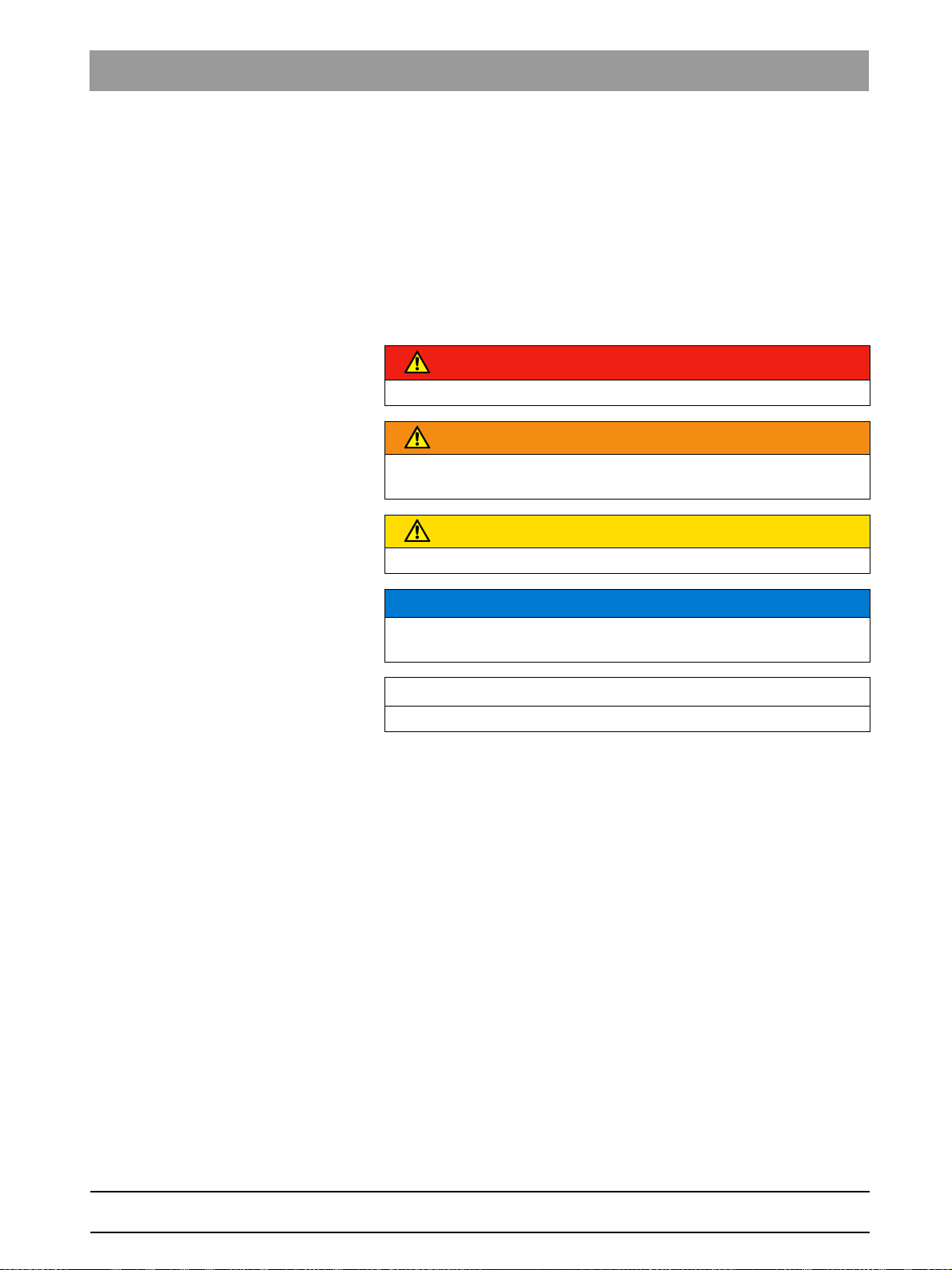
1.1.1 Identification of the danger levels
To prevent personal injury and material damage, please observe the
warning and safety information provided in the present operating
instructions. Such information is highlighted as follows:
DANGER
An imminent danger that could result in serious bodily injury or death.
WARNING
A possibly dangerous situation that could result in serious bodily injury
or death.
CAUTION
A possibly dangerous situation that could result in slight bodily injury.
NOTICE
A possibly harmful situation which could lead to damage of the product
or an object in its environment.
bеЦдблЬ
IMPORTANT
Application instructions and other important information.
Tip: Information on making work easier.
64 95 142 D3632
D3632.031.01.02.02 03.2016
9
Page 10
1About these Installation Instructions Sirona Dental Systems GmbH
1.1Structure of the document Installation Manual ORTHOPHOS SL
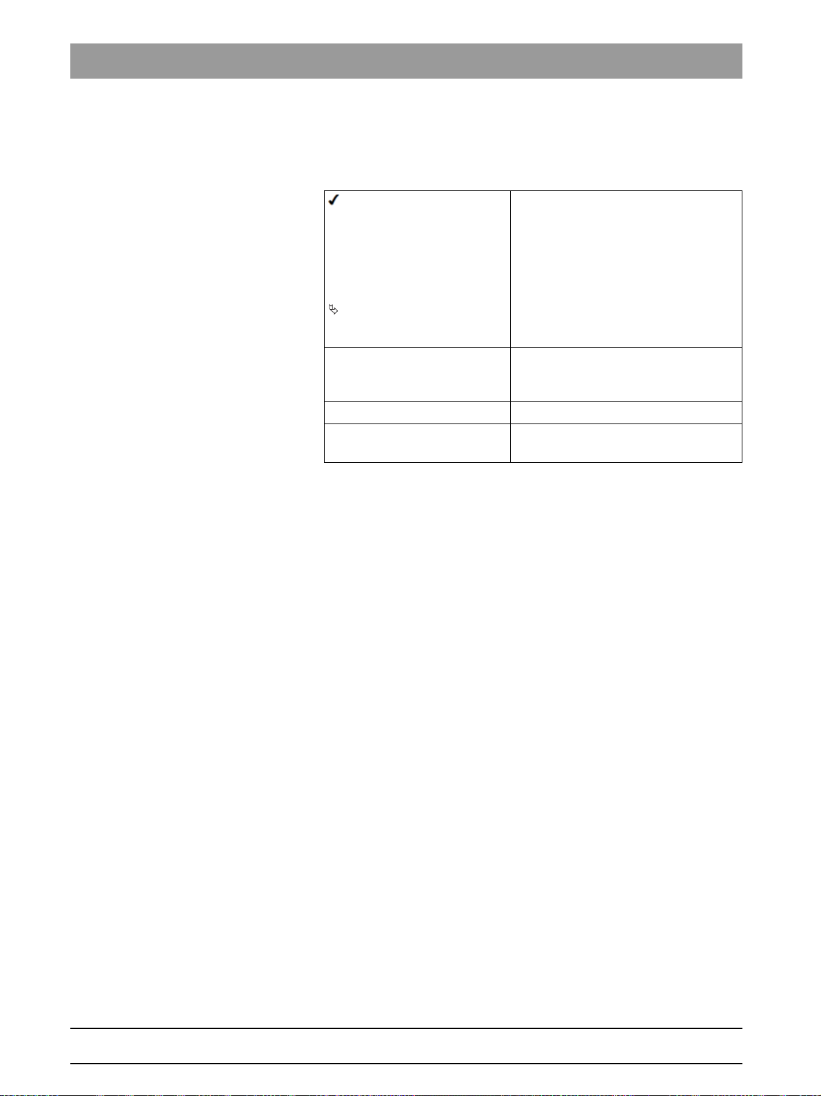
1.1.2 Formats and symbols used
The formats and symbols used in this document have the following
meaning:
Prerequisite
1. First action step
2. Second action step
or
➢ Alternative action
Result
➢ Individual action step
See "Formats and symbols
used [ → 10]"
● List Designates a list.
"Command / menu item" Indicates commands, menu items or
Requests you to do something.
Identifies a reference to another text
passage and specifies its page
number.
quotations.
10 D3632.031.01.02.02 03.2016
64 95 142 D3632
Page 11

Sirona Dental Systems GmbH 1About these Installation Instructions
Installation Manual ORTHOPHOS SL 1.2Scope
1.2
1.3
Scope
These installation instructions describe the installation of the
ORTHOPHOS SL digital X-ray unit/digital volume tomograph. They are
intended for use exclusively by trained and authorized distributors and
service technicians.
Other relevant documents
In addition to these installation instructions you will require the following
documentation:
Orthophos SL wiring diagrams
Wiring diagrams
● ORTHOPHOS SL Wiring References: REF 64 95 233
Installation of Orthophos SL
Installation Instructions
● ORTHOPHOS SL Software Installation: REF 65 44 287
● GALAXIS Operator's Manual: REF 61 23 488
● SIDEXIS 4 Installation Instructions: REF 64 47 200
Orthophos SL Service Manual
Service Manual
● ORTHOPHOS SL Service Manual: REF 64 95 258
DVD text
Current Service Documentation, such as the Service Manual, can be
downloaded from the Sirona dealer website.
bеЦдблЬ
64 95 142 D3632
D3632.031.01.02.02 03.2016
11
Page 12
2Safety instructions Sirona Dental Systems GmbH
2.1Information on the unit Installation Manual ORTHOPHOS SL
Safety instructions
2
Accompanying documents
Electrostatic discharge (ESD)
Identification of single use devices
2.1
Information on the unit
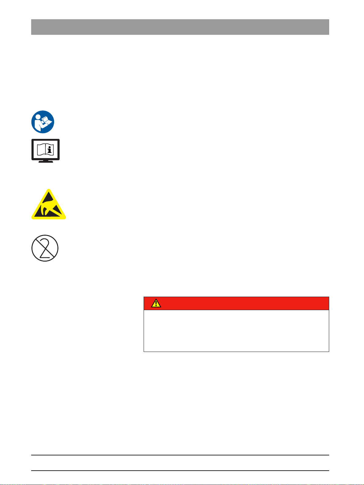
The following symbols are applied to the unit:
Accompanying documents
This symbol is affixed next to the unit rating plate.
Meaning: When operating the unit, observe the operating instructions.
This symbol is affixed on the unit rating plate.
Meaning: The accompanying documents are available on the homepage
of Sirona.
Connector pins or sockets bearing ESD warning labels must not be
touched or interconnected without ESD protective measures. See also
"Electrostatic Discharge" and "Electromagnetic Compatibility" [ → 14].
Single use hygienic protective sleeves
Prior to each exposure, the hygienic protective sleeves (single use
devices) must be fitted.
Single use devices are identified with the symbol shown on the left. They
must be disposed of immediately after use. Do not use single use devices
more than once.
2.2
Fixed connection
DANGER
Potentially lethal shock hazard!
Fixed connection!
Installing a mains plug instead of the specified fixed connection infringes
international medical regulatory actions and is prohibited. In case of
error, this puts patients, users, and other parties seriously at risk.
2.3
12 D3632.031.01.02.02 03.2016
Ventilation slots
Ventilation slots
Never cover the ventilation slots on the unit under any circumstances,
since this may obstruct air circulation. This can cause the unit to overheat.
SL sensor ventilation sl ots
Under no circumstances may the ventilation slots on the sensor unit be
covered, since otherwise the air circulation in the sensor unit will be
obstructed. This can cause the sensor unit to overheat.
64 95 142 D3632
Page 13
Sirona Dental Systems GmbH 2Safety instructions
Installation Manual ORTHOPHOS SL 2.4Condensation
2.4
2.5
2.6
2.7
Condensation
Safety information for co ndensation: Service engi neer
Extreme fluctuations of temperature may cause condensation inside the
unit. Do not switch the unit on before it has reached normal room
temperature. See also Technical Data.
Qualifications of service personnel
Installation and startup may be carried out only by personnel specifically
authorized by Sirona.
Switching the unit on
Safety information for switching on the unit: Service engineer
Due to the risk of injury caused by malfunction, no person may be
positioned in the unit when it is switched on.
Radiation protection
Safety information for rad iation protection: Service engineer
The valid radiation protection regulations and measures must be
observed. The statutory radiation protection equipment must be used.
During an exposure, the service engineer should move as far away from
the X-ray tube assembly as the coiled cable of the manual release
permits.
With the exception of the service engineer, no other persons are allowed
to stay in the room during an exposure.
bеЦдблЬ
2.8
In case of malfunctions, cancel the exposure immediately by letting go of
the exposure release button.
Information about radiat ion protection for Canada
NOTICE
3D imaging should not be used for screening examinations. 3D imaging
examinations must be clinically warranted and each exam must be
justified by demonstrating that the benefits outweigh the risks.
NOTICE
Where it is likely that evaluation of soft tissues will be required as part of
the patient's radiological assessment, the appropriate imaging should
be conventional medical CT or MR, rather than 3D imaging using Cone
Beam technology.
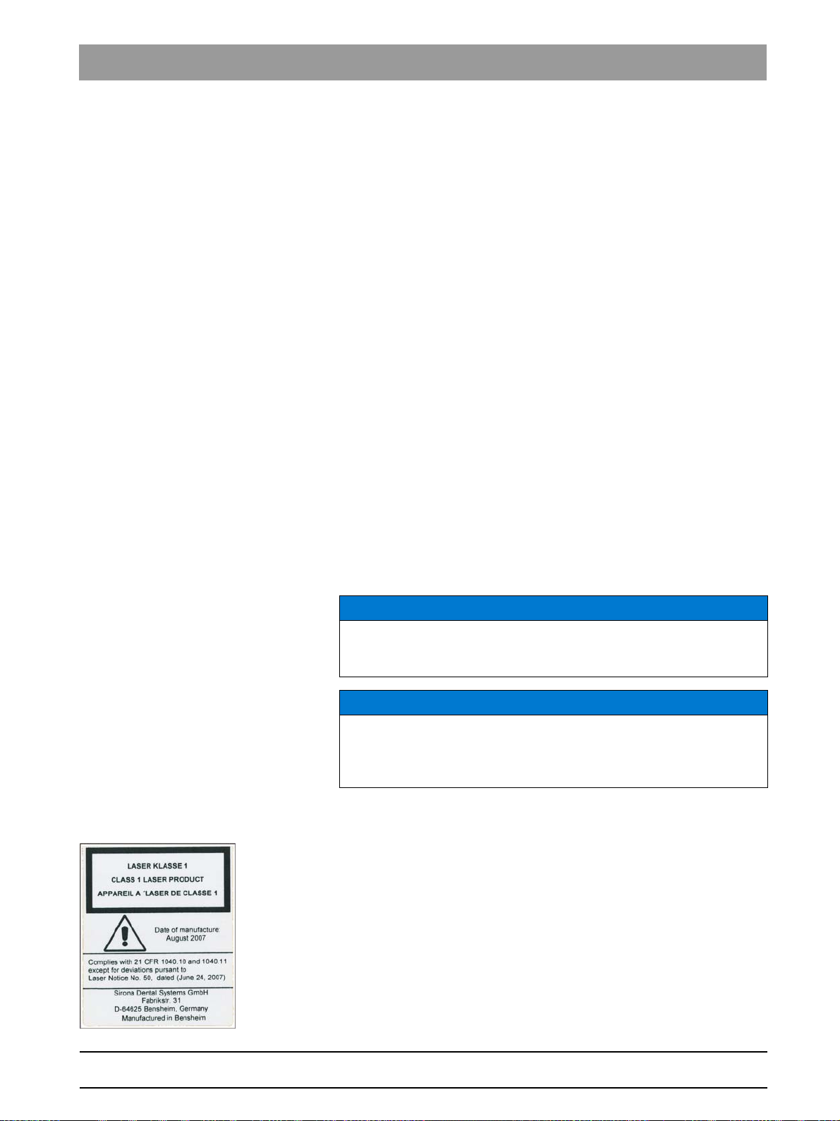
Laser light localizer
Safety information for light localizer: Service engineer
The system incorporates Class 1 laser products.
A minimum distance of 10 cm (4") is required between the eye and the
laser. Do not stare into the beam.
Do not use the system with any other lasers, and do not make any
changes to settings or processes that are not described in these
operating instructions. This may lead to a dangerous exposure to
radiation.
64 95 142 D3632
D3632.031.01.02.02 03.2016
13
Page 14
2Safety instructions Sirona Dental Systems GmbH
2.9Modifications to the unit Installation Manual ORTHOPHOS SL
2.9
2.10
2.11
Modifications to the unit
Modifications to this unit which might affect the safety of the system
owner, patients or other persons are prohibited by law!
For reasons of product safety, this product may be operated only with
original Sirona accessories or third-party accessories expressly approved
by Sirona. The user is responsible for any damage resulting from the use
of non-approved accessories.
Transport safety devices
Transport safety devices
IMPORTANT
The transport safety devices (marked in red) attached to the unit must
be removed prior to initial startup.
Electromagnetic compatibility
The unit complies with the requirements of standard IEC 60601-1-2.
Medical electrical equipment is subject to special EMC-related
precautions. It must be installed and operated as specified in the
document "Installation Requirements".
If high-voltage systems, radio link systems or MRI systems are located
within 5 m of the unit, please observe the specifications stated in the
installation requirements.
2.12
Portable and mobile RF communications equipment may affect medical
electrical equipment. Therefore, the use of mobile wireless phones in
medical office or hospital environments must be prohibited.
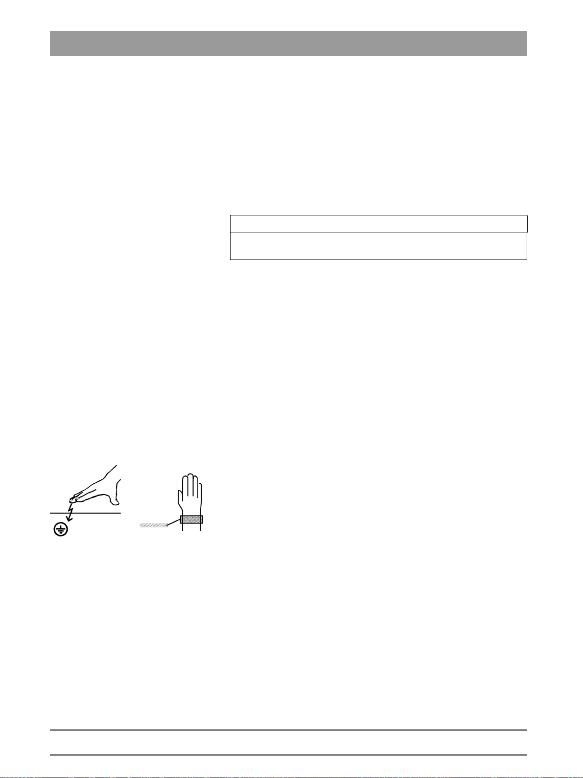
Electrostatic discharge
Electrostatic discharge (abbreviated: ESD – ElectroStatic Discharge)
Electrostatic discharge from people can damage electronic components
when the components are touched.
Touch a ground point to discharge static electricity before touching any
boards.
14 D3632.031.01.02.02 03.2016
64 95 142 D3632
Page 15
Sirona Dental Systems GmbH 3Unit description
A
B
C
Installation Manual ORTHOPHOS SL 3.1System version
Unit description
3
3.1
System version
bеЦдблЬ
64 95 142 D3632
D3632.031.01.02.02 03.2016
15
Page 16
3Unit description Sirona Dental Systems GmbH
3.1System version Installation Manual ORTHOPHOS SL
Version Description
A ORTHOPHOS SL 2D
Digital X-ray unit with DCS sensor
Pan sensor: Digital CdTe sensor
with direct converter technology for
panoramic exposure technology
ORTHOPHOS SL 3D
Digital X-ray unit with digital Flat
Panel Detector and DCS sensor
Flat Panel Detector: Digital Flat
Panel Detector with a-Si
technology (amorphous silicon)
Pan sensor: Digital CdTe sensor
with direct converter technology for
panoramic exposure technology
B ORTHOPHOS SL 2D/3D
Ceph, left-arm version
Digital X-ray unit ORTHOPHOS SL
(all variants A) with cephalometer,
left-arm version
C ORTHOPHOS SL 2D/3D
Ceph, right-arm version
Digital X-ray unit ORTHOPHOS SL
(all variants A) with cephalometer,
right-arm version
16 D3632.031.01.02.02 03.2016
64 95 142 D3632
Page 17
Sirona Dental Systems GmbH 3Unit description
Installation Manual ORTHOPHOS SL 3.2Sensor versions
3.2
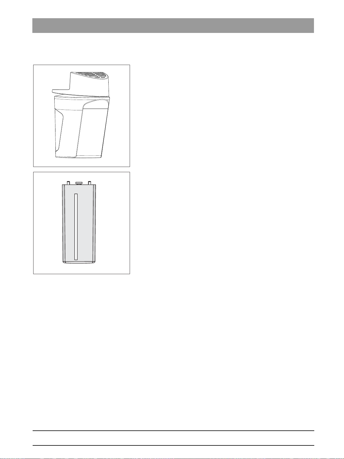
Sensor versions
2D sensor unit:
Sensor unit for panoramic X-ray (PAN): DCS sensor (2D)
2D/3D sensor unit:
Sensor unit for panoramic X-ray (PAN) and volume exposures (3D):
DCS sensor (2D) and flat panel detector (3D)
CEPH sensor: Sensor for cephalometric X-ray (Ceph) (2D)
bеЦдблЬ
64 95 142 D3632
D3632.031.01.02.02 03.2016
17
Page 18
3Unit description Sirona Dental Systems GmbH
3.3Dimensions/Space requirements Installation Manual ORTHOPHOS SL
3.3
Dimensions/Space requirements
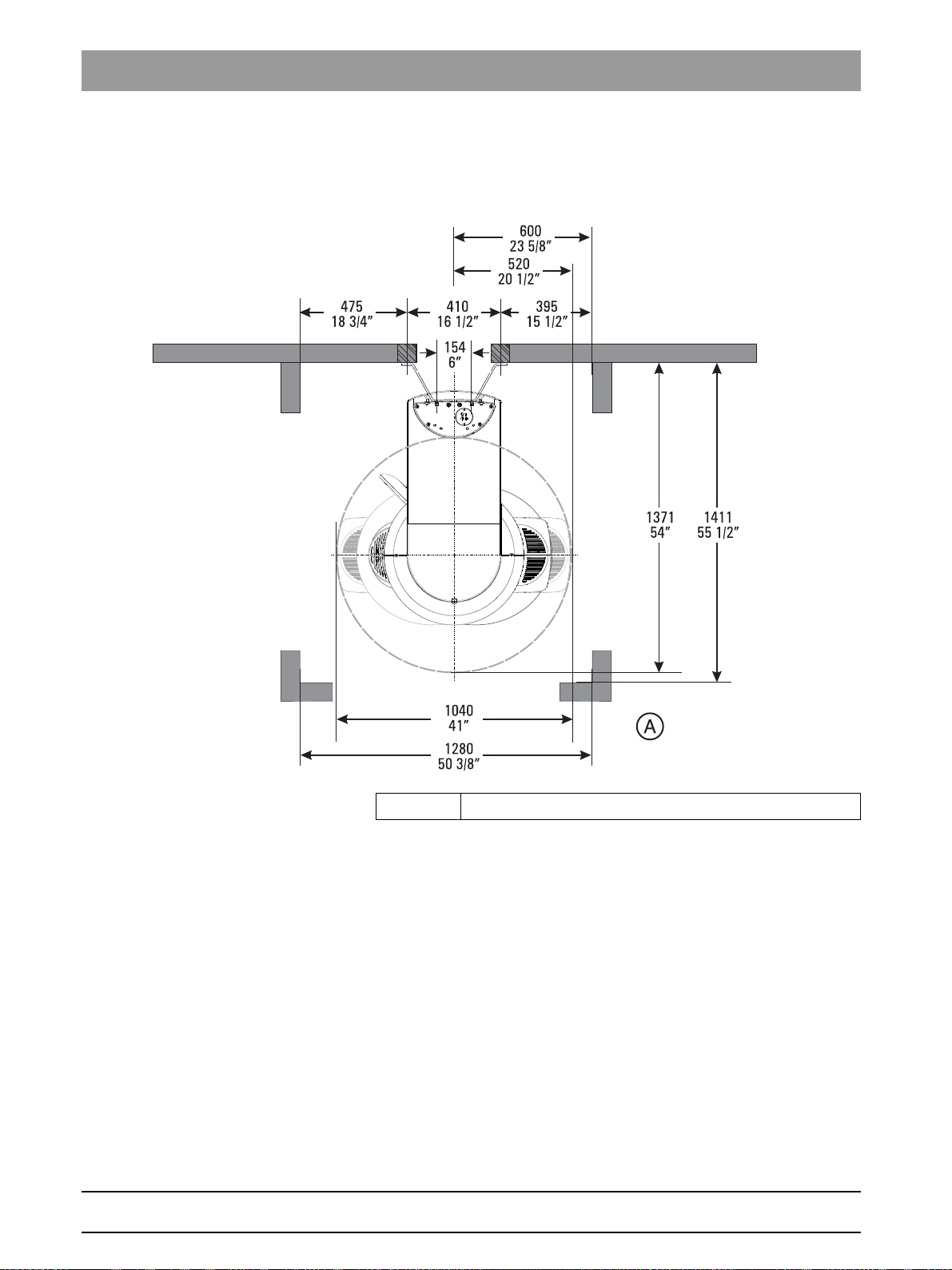
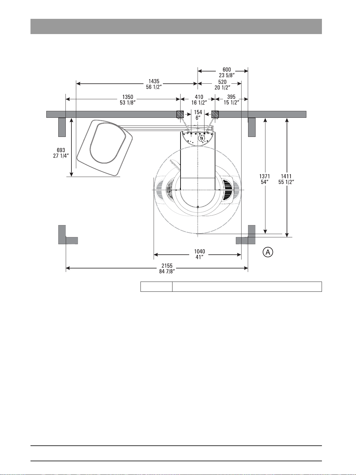
3.3.1 Top view
A Recommended distances from cabinet or wall
64 95 142 D3632
18 D3632.031.01.02.02 03.2016
Page 19
Sirona Dental Systems GmbH 3Unit description
Installation Manual ORTHOPHOS SL 3.3Dimensions/Space requirements
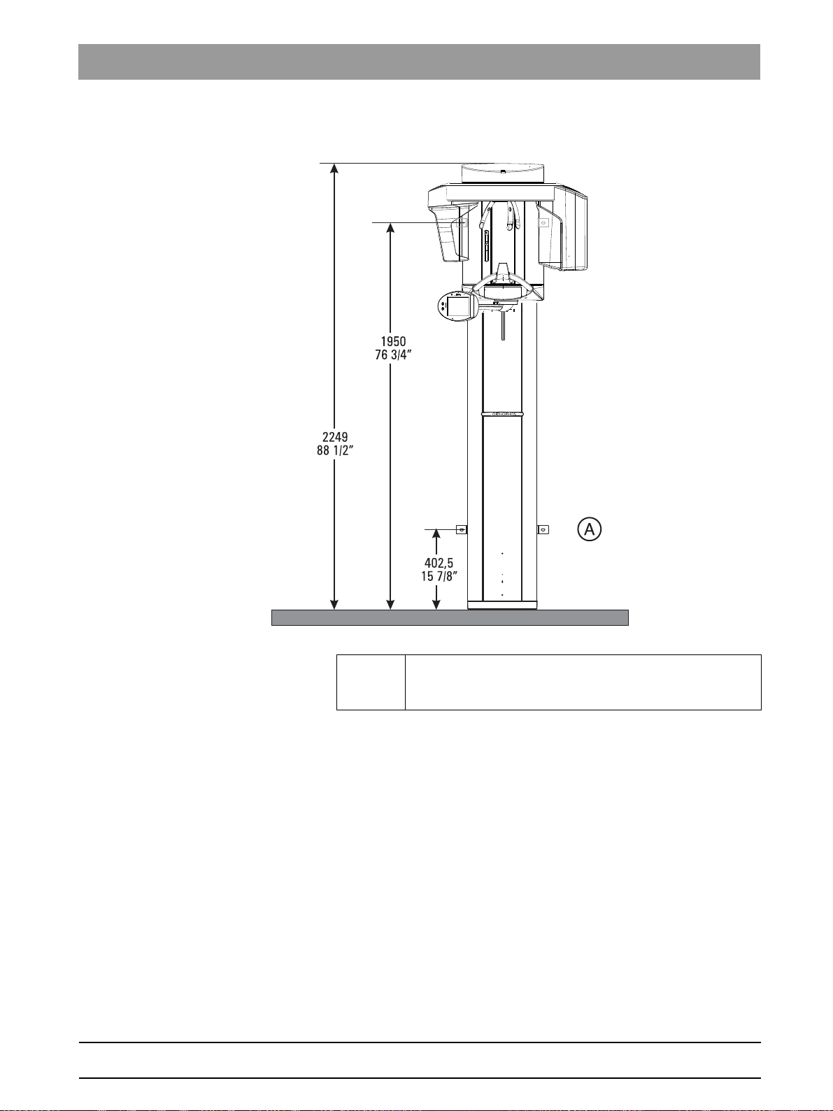
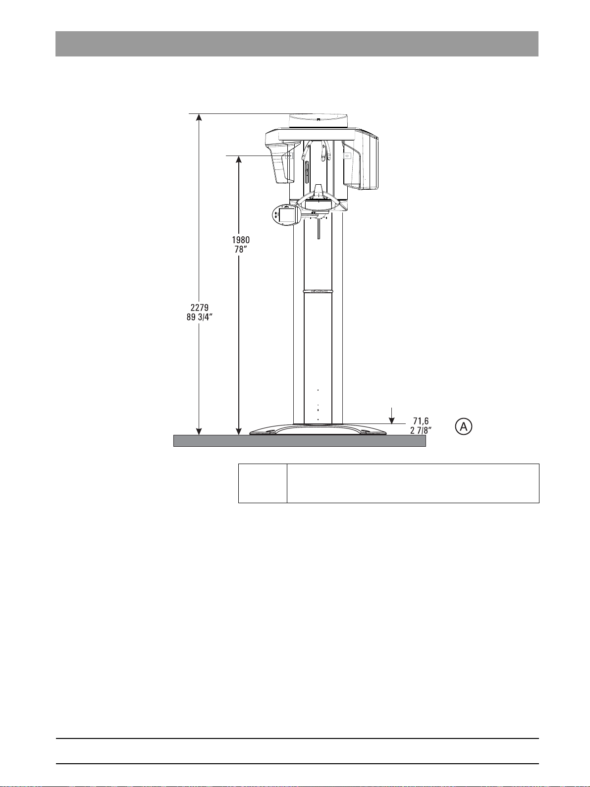
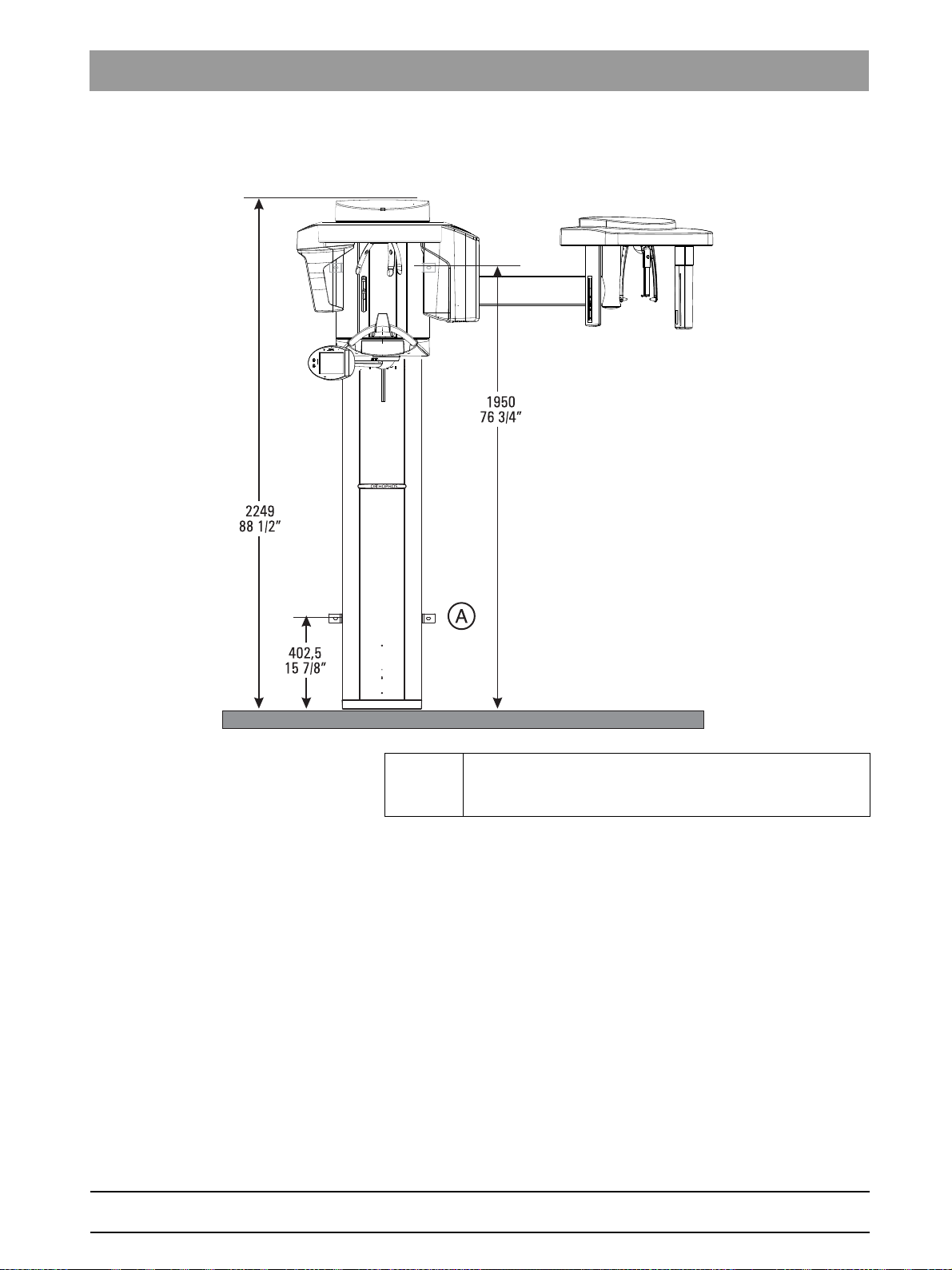
3.3.2 Front view
A Alternative fastening if it is not possible to screw the unit
onto the floor.
Order bracket separately.
bеЦдблЬ
64 95 142 D3632
D3632.031.01.02.02 03.2016
19
Page 20
3Unit description Sirona Dental Systems GmbH
3.3Dimensions/Space requirements Installation Manual ORTHOPHOS SL
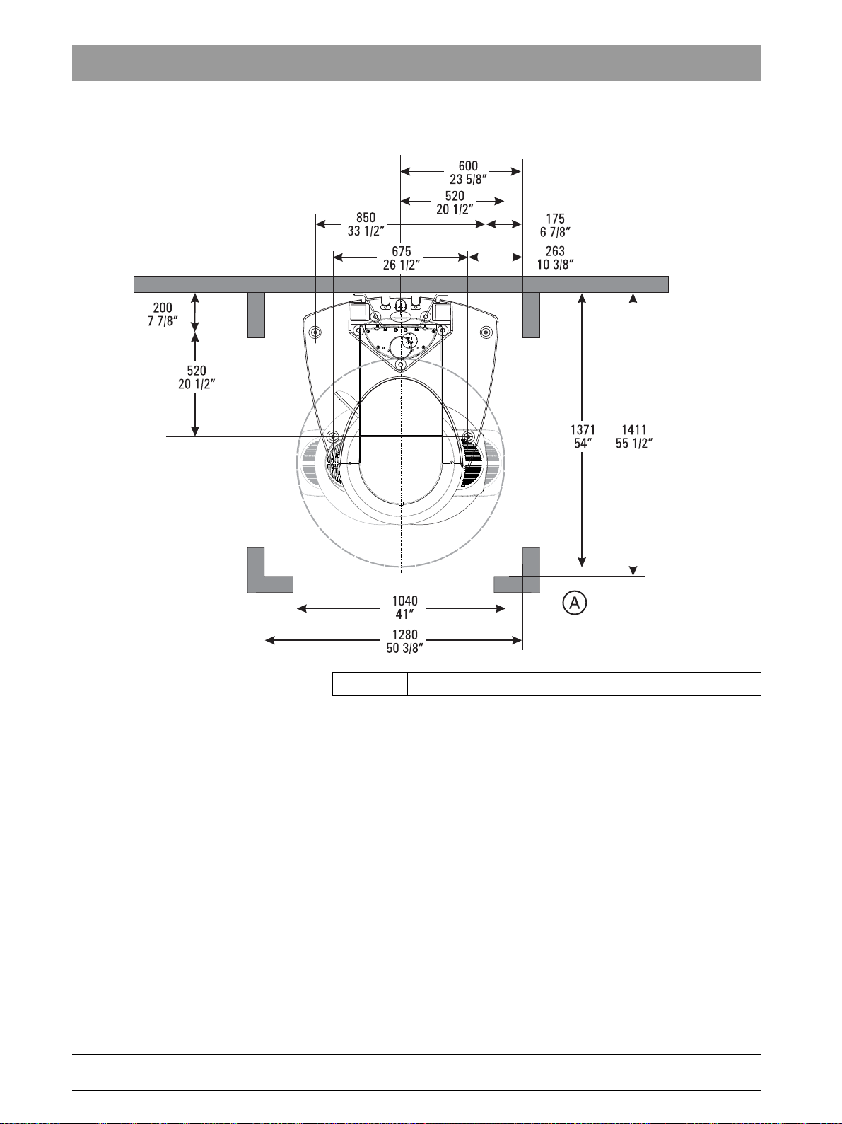
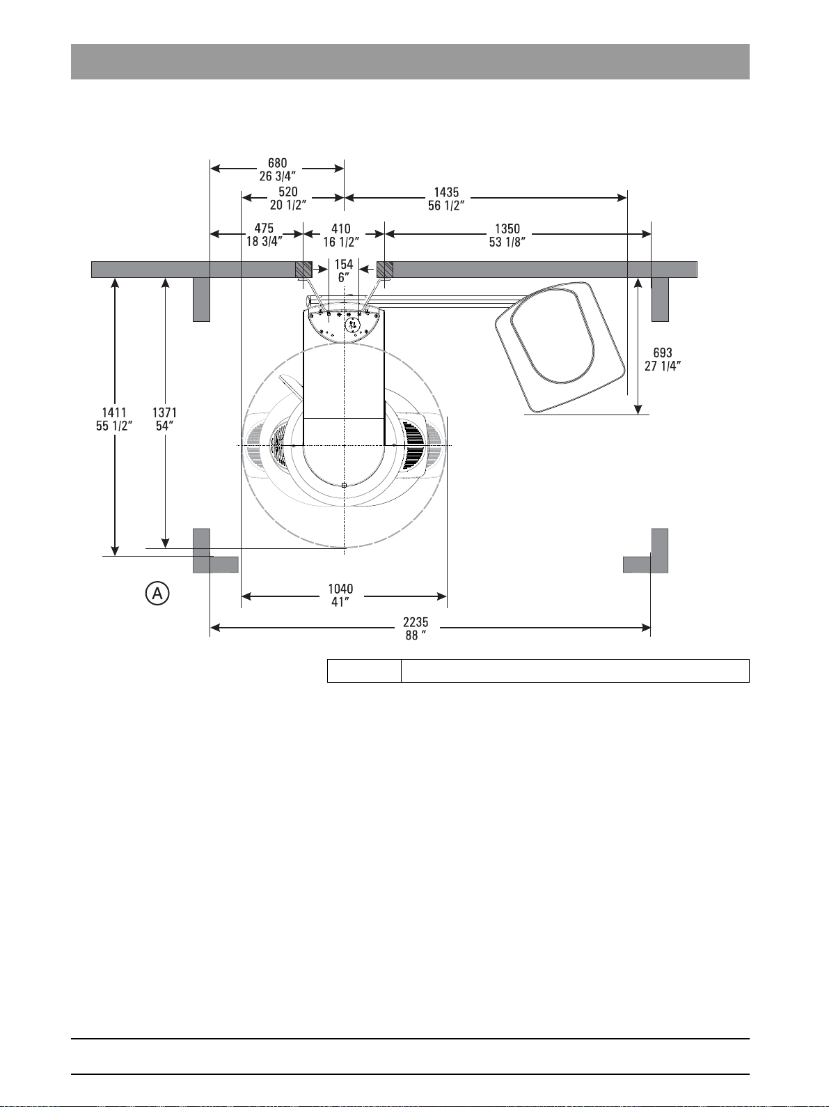
3.3.3 Top view with floor stand
A Recommended distances from cabinet or wall
64 95 142 D3632
20 D3632.031.01.02.02 03.2016
Page 21
Sirona Dental Systems GmbH 3Unit description
Installation Manual ORTHOPHOS SL 3.3Dimensions/Space requirements
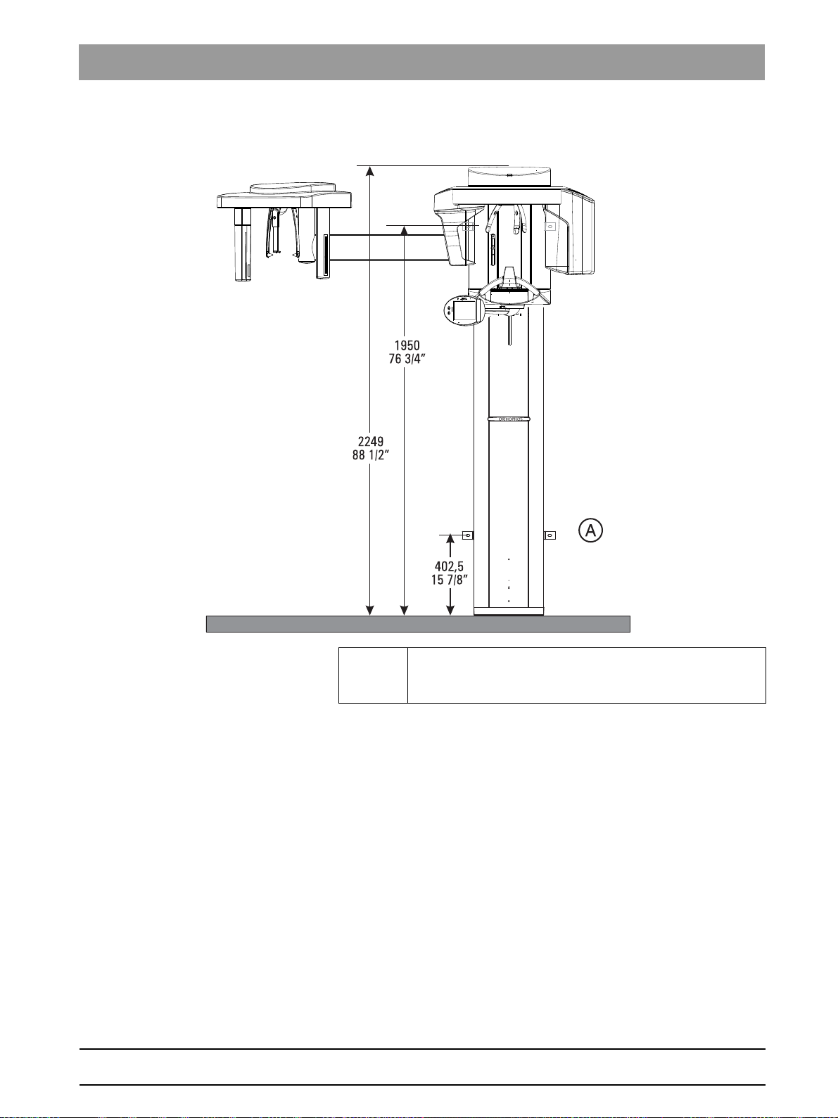
3.3.4 Front view with floor stand
A Floor stand:
Order floor stand separately.
The unit must also always be secured to the top wall holder.
bеЦдблЬ
64 95 142 D3632
D3632.031.01.02.02 03.2016
21
Page 22
3Unit description Sirona Dental Systems GmbH
3.3Dimensions/Space requirements Installation Manual ORTHOPHOS SL
3.3.5 Top view with Ceph left
A Recommended distances from cabinet or wall
64 95 142 D3632
22 D3632.031.01.02.02 03.2016
Page 23
Sirona Dental Systems GmbH 3Unit description
Installation Manual ORTHOPHOS SL 3.3Dimensions/Space requirements
3.3.6 Front view with Ceph left
A Alternative fastening if it is not possible to screw the unit
onto the floor.
Order bracket separately.
bеЦдблЬ
64 95 142 D3632
D3632.031.01.02.02 03.2016
23
Page 24
3Unit description Sirona Dental Systems GmbH
3.3Dimensions/Space requirements Installation Manual ORTHOPHOS SL
3.3.7 Top view with Ceph right
A Recommended distances from cabinet or wall
64 95 142 D3632
24 D3632.031.01.02.02 03.2016
Page 25
Sirona Dental Systems GmbH 3Unit description
Installation Manual ORTHOPHOS SL 3.3Dimensions/Space requirements
3.3.8 Front view with Ceph right
A Alternative fastening if it is not possible to screw the unit
onto the floor.
Order bracket separately.
bеЦдблЬ
64 95 142 D3632
D3632.031.01.02.02 03.2016
25
Page 26
3Unit description Sirona Dental Systems GmbH
C
B
A
3.4Mounting options Installation Manual ORTHOPHOS SL
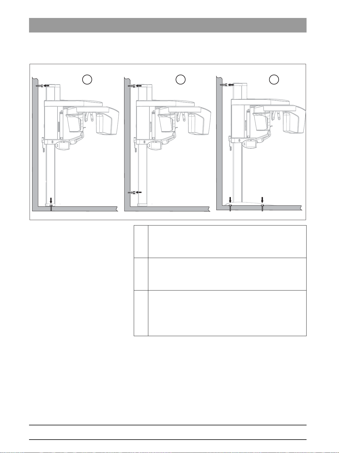
3.4
Mounting options
A Standard version
Wall-mounted installation with 1 wall holder
fastening if both wall and floor installation are possible on-site
(see section “Wall mounting (standard and option 1) [ → 49]”).
B Option 1
Wall-mounted installation with 2 wall holders
fastening) if only wall installation is possible on-site (see section
“Wall mounting (standard and option 1) [ → 49]”).
C Option 2
Installation using a floor stand and 1 wall holder
possible to mount the unit on the wall and on the floor on-site and
x-rays are often taken while the patient is seated on a chair →
better positioning of seated patient (see section “Installing the
floor stand (option 2) [ → 55]”).
(short) and floor
(short) (and no floor
(long) if it is
26 D3632.031.01.02.02 03.2016
64 95 142 D3632
Page 27
Sirona Dental Systems GmbH 3Unit description
Installation Manual ORTHOPHOS SL 3.5Installation versions
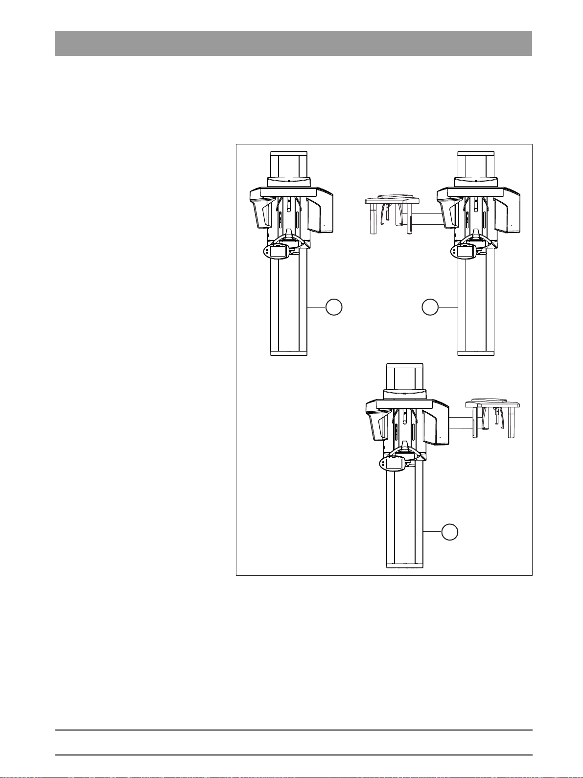
3.5
Installation versions
bеЦдблЬ
64 95 142 D3632
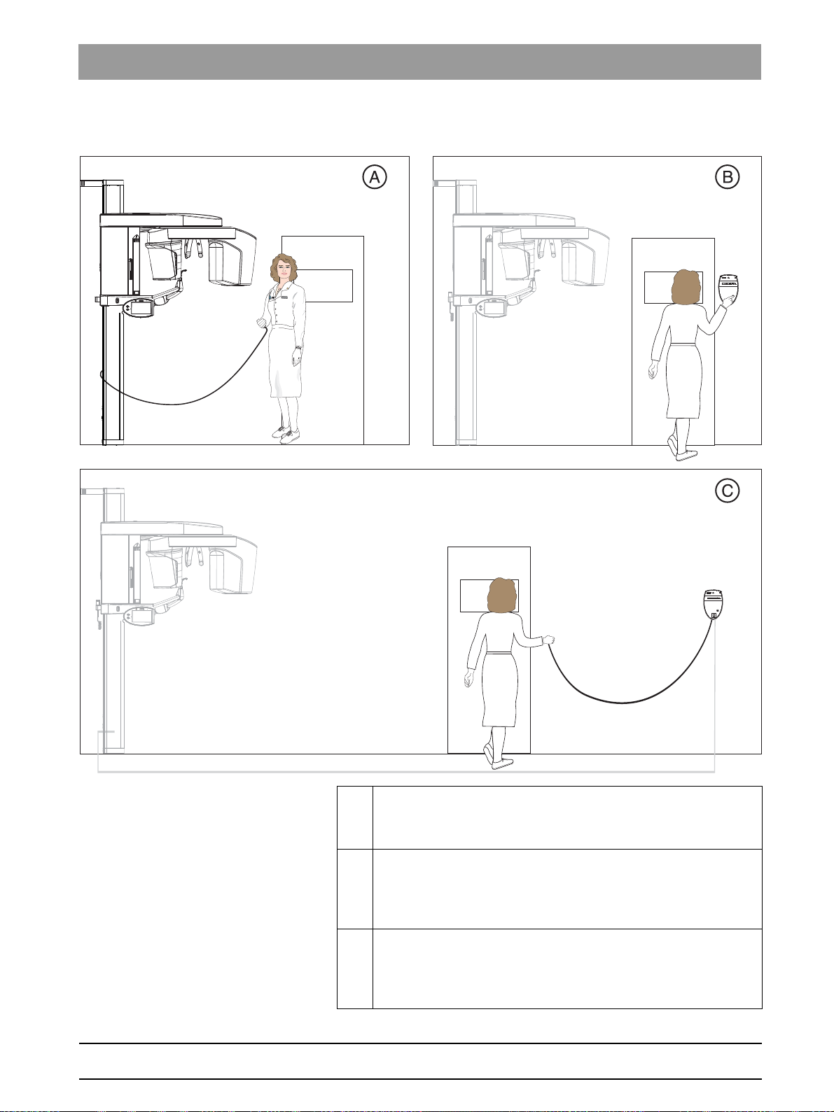
D3632.031.01.02.02 03.2016
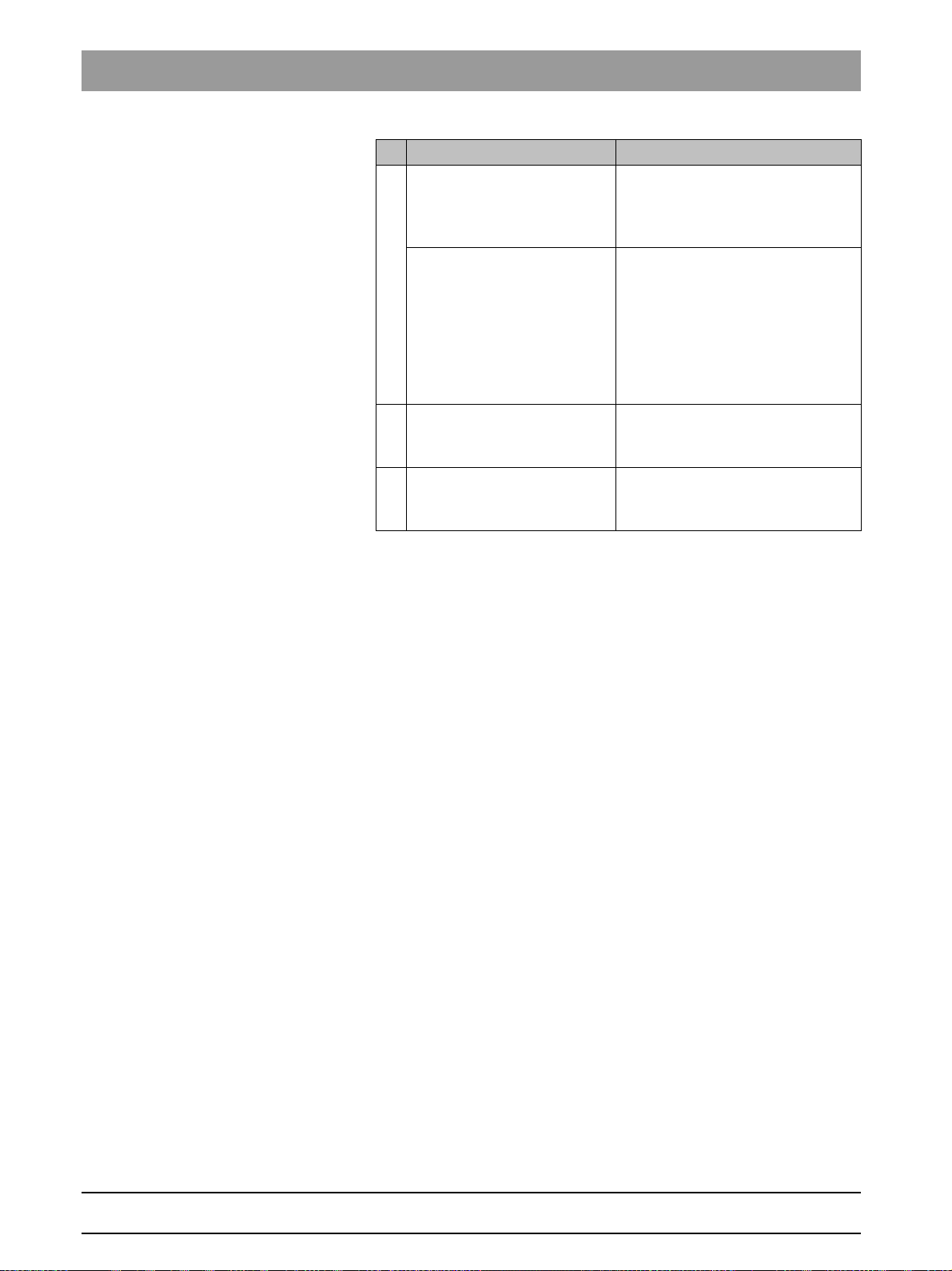
A Standard installation
Unit
without remote control with release button on the coiled cable
in the treatment room.
B Installation version 1
Unit
with remote control
button on the coiled cable.
Without coiled cable [ → 76]”).
C Installation version 2
Unit
with remote control
button on the coiled cable.
With spiral cable [ → 77]”).
outside the X-ray room
(see section “Installation version 1:
outside the X-ray room
(see section “Installation version 2:
without release
with release
27
Page 28
4Delivery and transport Sirona Dental Systems GmbH
A
B
A
4.1Operating and transport conditions Installation Manual ORTHOPHOS SL
Delivery and transport
4
4.1
4.2
Operating and transport conditions
Transport and storage
temperature:
Air humidity: 10 % – 95 %
Admissible operating
temperature:
Operating altitude: ≤ 3,000 m above sea level
-10°C – +70°C (14°F – 158°F)
+18 °C - +31 °C (64 °F – 88 °F)
Delivery
Damage following delivery
NOTICE
Possible transport damage
If the shipment was damaged during transport, document all damage
carefully and contact the responsible carrying agent immediately.
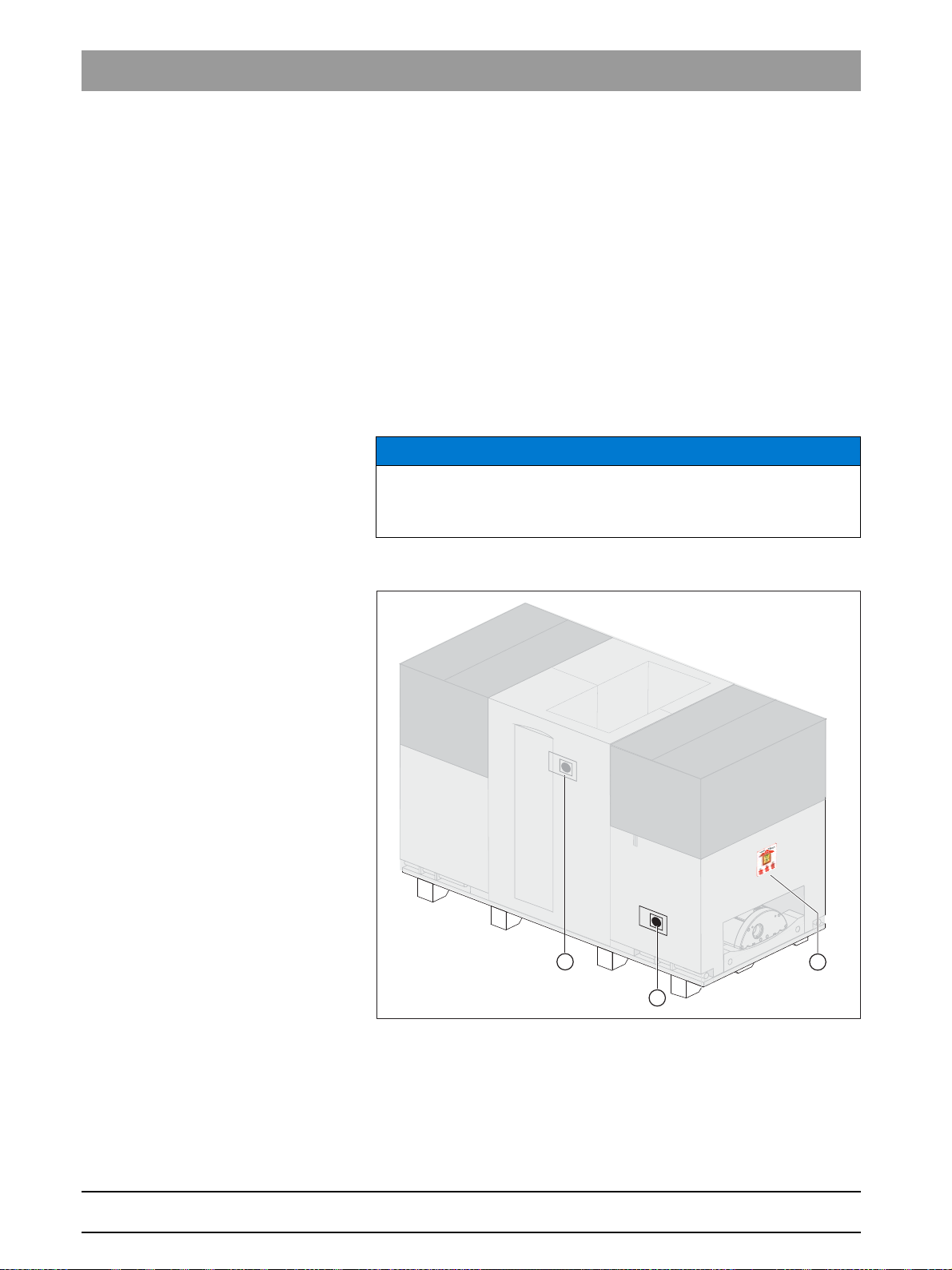
Indicators
Two shock indicators (A) are attached to the side of the X-ray unit
packaging to indicate whether the unit was exposed to a shock during
transport.
● White indicator: No shock
● Red indicator: Shock
28 D3632.031.01.02.02 03.2016
64 95 142 D3632
Page 29
Sirona Dental Systems GmbH 4Delivery and transport
Installation Manual ORTHOPHOS SL 4.2Delivery
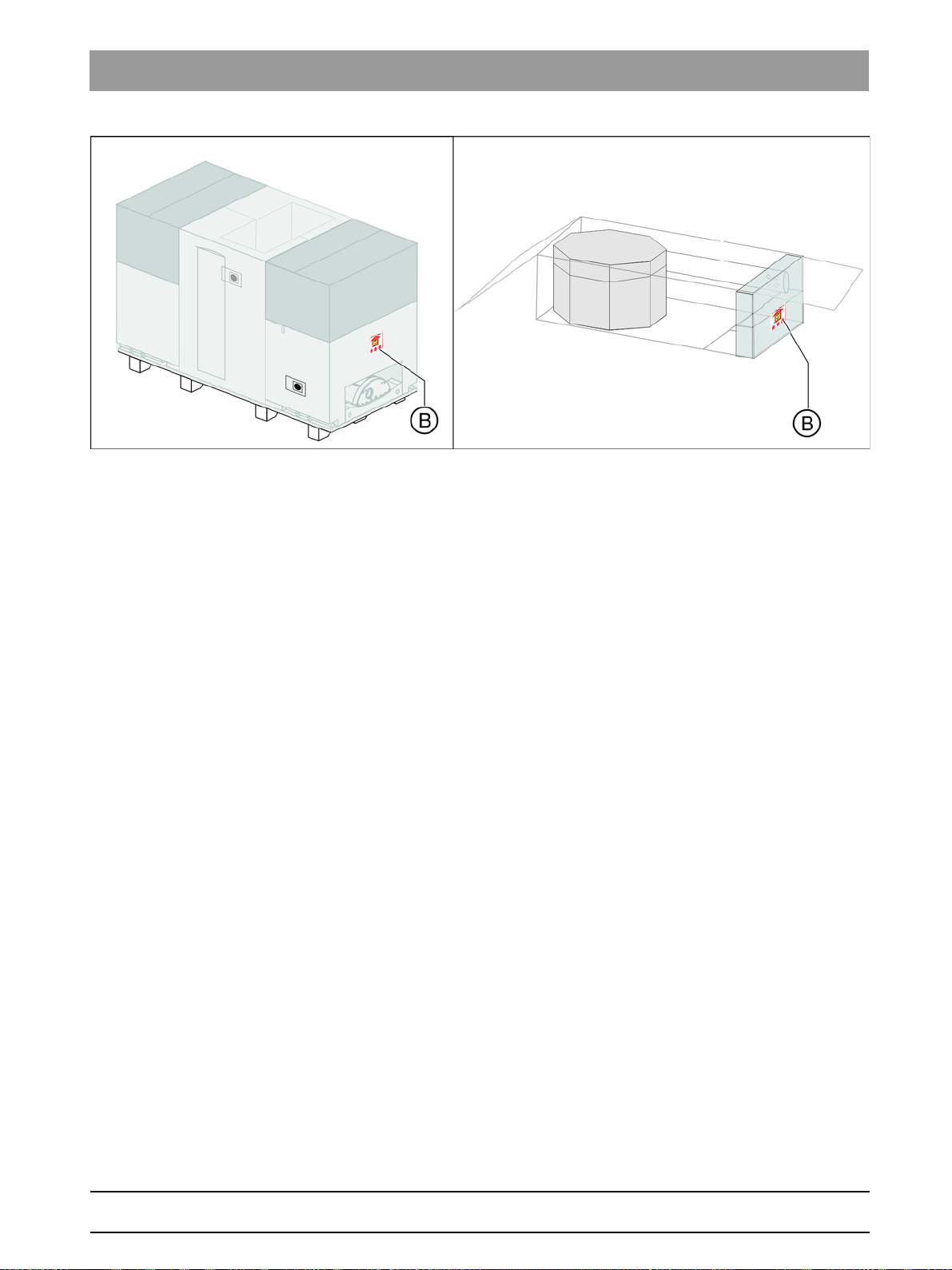
Tilt indicators (B) are attached to the X-ray unit and cephalometer
packaging to indicate whether the units were improperly transported.
● Red indicator: Improper transport
The display of improper transport doesn't necessarily mean that the unit
is damaged.
bеЦдблЬ
Make a note on the delivery slip that the indicator is activated. Ensure that
the driver from the transport company confirms this on the delivery slip.
Fax the delivery slip to the Sirona Customer Service Center (CSC).
Enter the state of the indicators in the startup report in the case of
warranty claims.
Disposal of packaging materials
Disposal of packaging materials
Return the packaging materials to Sirona or dispose of them in
compliance with the legal regulations applicable in your country.
64 95 142 D3632
D3632.031.01.02.02 03.2016
29
Page 30

4Delivery and transport Sirona Dental Systems GmbH
A
A
G
F
C
B
D
E
4.2Delivery Installation Manual ORTHOPHOS SL
4.2.1 ORTHOPHOS SL
Dimensions and weight
Dimensions Length Width Height
in cm 199 69 122
in inches 78 3/4 27 1/8 48
Weight in kg 186
in lbs 410
Scope of supply
The packaging of the X-ray unit is designed both for protection during
transport and as an installation aid. Therefore, please remove only the
surrounding packaging prior to installation. Please leave the Styrofoam
packaging and transport pallet attached to the unit. Save the two lateral
styrofoam packaging parts for later use as an installation aid (A).
64 95 142 D3632
30 D3632.031.01.02.02 03.2016
Page 31

Sirona Dental Systems GmbH 4Delivery and transport
H
I
Installation Manual ORTHOPHOS SL 4.2Delivery
A Installation aid (please save the two lateral Styrofoam packaging
parts)
Scope of supply:
B Filling piece 1
C Filling cardboard 1
D Pack list 1
E Filling cardboard 2
F Filling piece 2 including pack list 2
G Profile cover
➢ Check the scope of delivery using pack lists 1 and 2.
IMPORTANT
Tube assembly guard
The X-ray tube assembly is protected by a tube assembly guard (H) and
a tension belt (I) in its packing position. Keep the tube assembly and the
tension belt in a safe place for possible repacking.
bеЦдблЬ
64 95 142 D3632
D3632.031.01.02.02 03.2016
31
Page 32

4Delivery and transport Sirona Dental Systems GmbH
4.2Delivery Installation Manual ORTHOPHOS SL
4.2.2 Sensors
DCS sensor
A Styrofoam packaging
Scope of supply:
B DCS sensor
32 D3632.031.01.02.02 03.2016
64 95 142 D3632
Page 33

Sirona Dental Systems GmbH 4Delivery and transport
A
B
Installation Manual ORTHOPHOS SL 4.2Delivery
Flat Panel Detector
bеЦдблЬ
A Styrofoam packaging
Scope of supply:
B Flat Panel Detector
64 95 142 D3632
D3632.031.01.02.02 03.2016
33
Page 34

4Delivery and transport Sirona Dental Systems GmbH
4.2Delivery Installation Manual ORTHOPHOS SL
4.2.3 Ceph arm
Dimensions and weight
Dimensions (cm) 175 x 78 x 73
(inches) 68 7/8 x 30 3/4 x 28 3/4
Weight (kg) 40
(lbs) 88
Scope of supply
IMPORTANT
The right-handed ceph arm is packed laterally reversed.
A Styrofoam packaging
Scope of supply:
B Ceph arm
C Accessories [ → 35] and hygienic protective sleeves [ → 35]
D Installation material [ → 89]
E Ceph sensor
Damage to the cephalometer
NOTICE
Risk of damage to the cephalometer
The cephalometer inside the styrofoam part (A) is a sensitive unit and is
at risk of damage when mounting the ceph arm. Remove the styrofoam
packaging material only following installation.
34 D3632.031.01.02.02 03.2016
64 95 142 D3632
Page 35

Sirona Dental Systems GmbH 4Delivery and transport
20
30
40
50
C
A
B
20
30
40
50
B
A
Installation Manual ORTHOPHOS SL 4.2Delivery
4.2.3.1
Accessories
A Nose support (1x)
B Ear plug holders with ear plug fixation (2x)
C Carpus support plate (1x)
bеЦдблЬ
4.2.3.2
Hygienic protection
A Hygienic protective sleeves for nose support (100x)
B Hygienic caps for ear plugs, sterilizable (4x)
64 95 142 D3632
D3632.031.01.02.02 03.2016
35
Page 36

4Delivery and transport Sirona Dental Systems GmbH
A
B
A
C
B
4.2Delivery Installation Manual ORTHOPHOS SL
4.2.4 Adjustment sets
2D adjustment: Panoramic
A Needle phantom
B Set of Torx offset screwdrivers
2D adjustment: Cephalometer
A Ceph adjustment
phantom
B Adjusting caps (1x black, 1x transparent)
C Torx offset screwdriver
36 D3632.031.01.02.02 03.2016
64 95 142 D3632
Page 37

Sirona Dental Systems GmbH 4Delivery and transport
A
A
Installation Manual ORTHOPHOS SL 4.2Delivery
3D adjustment/calibration
A Geometry phantom
Acceptance and constancy test
Worldwide
3D constancy test, worldwide
A Constancy test unit
B Contrast element
bеЦдблЬ
64 95 142 D3632
D3632.031.01.02.02 03.2016
37
Page 38

4Delivery and transport Sirona Dental Systems GmbH
B
A
C
4.2Delivery Installation Manual ORTHOPHOS SL
For Germany only
3D constancy test, Germany
A DVT test phantom - DIN
B Contrast element
C Test phantom 0.8mm CU Ceph
38 D3632.031.01.02.02 03.2016
64 95 142 D3632
Page 39

Sirona Dental Systems GmbH 4Delivery and transport
B
A
Installation Manual ORTHOPHOS SL 4.3Transport to the installation site
4.3
Transport to the installation site
4.3.1 ORTHOPHOS SL
NOTICE
Possible transport damage
Leave the packaging attached to the unit during the entire transport to
the installation site.
4.3.1.1
Transport with packaging attached (normal case)
NOTICE
Unit can tilt
In its transport position, the center of gravity of the unit is very high.
➢ Take care that the unit does not tip over during transport.
1. Open the surrounding packaging using the straps provided (A).
2. Pull out the carrying handles (B).
3. Transport the unit to the installation site.
bеЦдблЬ
64 95 142 D3632
D3632.031.01.02.02 03.2016
39
Page 40

4Delivery and transport Sirona Dental Systems GmbH
C
E
4.3Transport to the installation site Installation Manual ORTHOPHOS SL
4.3.1.2
Transport without pallet (exception)
If the pallet is too wide for transport to the installation site, you may
unscrew the pallet from the wooden support (A) and transport the unit by
means of the wooden supports without the pallet.
NOTICE
Possible transport damage
Leave the center styrofoam packaging attached to the unit for
protection.
If this is not possible, secure the position of the tube assembly prior to
further transport.
➢ Secure the position of the tube assembly using the strap provided
(see label on the styrofoam packaging).
➢ Tighten the strap only gently. Do not tension the strap.
1. Remove the surrounding packaging.
2. Take the remote control (if supplied) out of the center styrofoam
packaging and store everything in a safe place.
3. Remove the two lateral styrofoam packaging parts.
4. Loosen the four screws (B).
5. Pull the carrying handles (C) out of their holders and insert them
through the drillings (D) of the wooden support (A) from the inside.
6. Insert screws (B) through drillings (E) and into the drillings of the
carrying handles to attach them firmly. The handles can be made
short or long.
The carrying handles have rims which prevent them from slipping out
of the holes.
40 D3632.031.01.02.02 03.2016
64 95 142 D3632
Page 41

Sirona Dental Systems GmbH 4Delivery and transport
Installation Manual ORTHOPHOS SL 4.3Transport to the installation site
4.3.2 Sensors
NOTICE
Possible transport damage
The pan sensor and flat panel detector are sensitive instruments. Only
remove the packaging immediately prior to installing the sensors on the
unit.
4.3.3 Ceph arm
NOTICE
Risk of damage to the cephalometer
The cephalometer inside the styrofoam part (B) is a sensitive unit and is
at risk of damage when mounting the ceph arm. Remove the styrofoam
packaging material only following installation.
IMPORTANT
The right-handed ceph arm is packed laterally reversed.
1. Open the cardboard case and remove the styrofoam part (B).
2. Lift the ceph arm out of the cardboard packaging and transport it to
the installation site.
bеЦдблЬ
64 95 142 D3632
D3632.031.01.02.02 03.2016
41
Page 42

5Installation: X-ray unit Sirona Dental Systems GmbH
5.1Installation material Installation Manual ORTHOPHOS SL
Installation: X-ray unit
5
5.1
5.1.1 Standard version
Installation material
A For installation on wooden stud frame structures
42 D3632.031.01.02.02 03.2016
64 95 142 D3632
Page 43

Sirona Dental Systems GmbH 5Installation: X-ray unit
Installation Manual ORTHOPHOS SL 5.1Installation material
Wall/floor mounting
Hexagon wood screw 8x80 (5/16x3") 4 pc.
Plastic wall plug S10 2 pc.
Screw M8x30 2 pc.
Washer Ø 8.4 6 pc.
M8 nut 2 pc.
Screw M4x10 18 pc
Washer Ø 4.3 2 pc.
Mounting kit Ø 10 SXR 2 pc.
TORX offset screwdrivers TX10, TX20, TX25 1 pc. each
Allen wrench (size 6) 1 pc.
Wall holder (long): 1 pc.
Wall holder cover (long) 2 pc.
Intermediate piece 1 pc.
Release button holder 1 pc.
bеЦдблЬ
64 95 142 D3632
D3632.031.01.02.02 03.2016
43
Page 44

5Installation: X-ray unit Sirona Dental Systems GmbH
5.1Installation material Installation Manual ORTHOPHOS SL
5.1.2 Option 1: with second wall holder
A For installation on wooden stud frame structures
Additional wall holder (for bottom wall mounting)
Wall holder (long): 1 pc.
Hexagon wood screw 8x80 (5/16x3") 2 pc.
Washer Ø 8.4 3 pc.
Hexagon head screw M8x50 1 pc.
M8 nut 1 pc.
Mounting kit Ø 10 SXR 2 pc.
Profile clamp 1 pc.
Wall holder cover (long) 2 pc.
44 D3632.031.01.02.02 03.2016
64 95 142 D3632
Page 45

Sirona Dental Systems GmbH 5Installation: X-ray unit
B
A
C
Installation Manual ORTHOPHOS SL 5.1Installation material
5.1.3 Option 2: Floor stand installation
A Mounting hardware
B Floor stand
C Floor stand covers
bеЦдблЬ
64 95 142 D3632
D3632.031.01.02.02 03.2016
45
Page 46

5Installation: X-ray unit Sirona Dental Systems GmbH
5.1Installation material Installation Manual ORTHOPHOS SL
Installation with floor stand
Floor stand 1 pc.
Floor stand cover 1 pc.
Wood screw 10x160 (3/8x6") 5 pc.
Plastic wall plug S12 5 pc.
Screw M8x80 2 pc.
Washer Ø 8.4 2 pc.
M8 nut 2 pc.
Screw M10x50 1 pc.
Profile clamp 1 pc.
Screw M5x12 1 pc.
Washer Ø 10.5 10 pc.
M10 nut 1 pc.
Spring steel clamp 8 pc.
Screw M10x25 4 pc.
Wood screw M10x80 (3/8x3) 5 pc.
46 D3632.031.01.02.02 03.2016
64 95 142 D3632
Page 47

Sirona Dental Systems GmbH 5Installation: X-ray unit
Ø 10mm
Installation Manual ORTHOPHOS SL 5.2Tools, materials, and measurement tools you will need
5.2
Tools, materials, and measurement tools you will need
5.2.1 Tools and materials
Masonry drill bit 10 mm
● Masonry drill bit 10mm (3/8")
Drill/hammer drill (gener al purpose)
● Drill or drill hammer, depending on the ground
Graphics: Open-end wre nch, neutral
Open-end wrench, 13 mm A/F
● Open-end wrench, 13 mm A/F
Socket wrench
Wrench insert 13
● Socket wrench
– Wrench insert 13
Hammer (general purpose)
● Hammer
Center punch (general purpose)
bеЦдблЬ
● Center punch
Spirit level (general purpose)
● Spirit level
● Adhesive tape
Included in the scope of supply:
Torx offset screwdriver, graphics
Torx offset screwdrivers TX10, TX20, TX25
● Offset screwdriver, Torx
–TX10
–TX20
–TX25
64 95 142 D3632
D3632.031.01.02.02 03.2016
47
Page 48

5Installation: X-ray unit Sirona Dental Systems GmbH
Ø 12mm
5.2Tools, materials, and measurement tools you will need Installation Manual ORTHOPHOS SL
Additional requirements for installation with floor stand:
Masonry drill bit 12mm
● Masonry drill bit 12mm (1/2")
Graphics: Neutral Allen wrench
Hexagon socket 2 mm
● Allen key 2 mm
Socket wrench
Socket wrench and extens ion 17
● Socket wrench and extension
Wrench insert 17
5.2.2 Measurement tools
● Multimeter or ammeter
● Test unit to measure unit leakage current
e.g. Bender tester or line-frequency, high-resistance measurement
voltage source (isolation transformer) and measuring circuit (MD)
that meets the requirements of IEC 60 601-1.
● Current source for protective conductor test
Technical data:
– No-load voltage min. 4 V - max. 24 V
– Short-circuit current min. 0.2 A
48 D3632.031.01.02.02 03.2016
64 95 142 D3632
Page 49

Sirona Dental Systems GmbH 5Installation: X-ray unit
2x 8x80
2x Ø 8,4
Installation Manual ORTHOPHOS SL 5.3Wall mounting (standard and option 1)
5.3
In case of mounting on weight-bearing
wood structures
Wall mounting (standard and option 1)
NOTICE
Reduced image quality
Note the wall and ground conditions. If a carpet is present at the unit
installation site, it must be removed.
Each wall plug must support a tensile force of 700 N.
The wall construction must be suitable for the installation of the unit.
Use the enclosed wood screws and washers from the mounting kit for
mounting the unit on weight-bearing wood structures.
bеЦдблЬ
Setting up the unit
NOTICE
Possible transport damage
Leave the center styrofoam packaging attached to the unit for
protection.
1. Remove the profile cover (A).
2. Position the two installation aids (B) at the foot (C) of the unit and
secure their position with adhesive tape.
CAUTION! The installation aids must be placed on top of each other
in such a way that their openings lie on top of each other.
64 95 142 D3632
D3632.031.01.02.02 03.2016
49
Page 50

5Installation: X-ray unit Sirona Dental Systems GmbH
5.3Wall mounting (standard and option 1) Installation Manual ORTHOPHOS SL
3. Set up the unit by tilting the transport pallet upward.
Tip: If you have transported the unit on the wooden support without a
pallet, set the unit upright with the wooden support. You can also use
the lateral styrofoam packaging as a support with this variation.
4. Loosen the nuts with washers (D) on both sides of the pallet (or
wooden support).
5. Take off the pallet (or wooden support).
6. Remove the threaded bolts (E).
Tip: Remove the lower bolts first, then the upper bolts.
The nuts (F) on the unit may remain inside the unit when the threaded
rods are removed. Remove the upper nuts. The lower nuts may
remain in the unit.
50 D3632.031.01.02.02 03.2016
64 95 142 D3632
Page 51

Sirona Dental Systems GmbH 5Installation: X-ray unit
410 mm
16 1/8”
1950 mm
76 3/4”
Ø 10mm
Ø 3/8”
Installation Manual ORTHOPHOS SL 5.3Wall mounting (standard and option 1)
Mounting the first (upper) wall holder (standard)
➢ Mount the upper wall holder.
bеЦдблЬ
Mounting the second (lower) wall holder (option 1)
➢ Mount the lower wall holder.
64 95 142 D3632
D3632.031.01.02.02 03.2016
51
Page 52

5Installation: X-ray unit Sirona Dental Systems GmbH
2x M 8
2x Ø 8,4
2x M 8x30
A
B
1x Ø 8,4
1x M 8x50
C
D
1xM8
1x
E
F
5.3Wall mounting (standard and option 1) Installation Manual ORTHOPHOS SL
Mounting the unit on the wall holder (standard and option 1)
NOTICE
Possible transport damage
Leave the middle styrofoam packaging on the unit throughout the entire
installation.
If, due to on-site conditions, it is necessary to remove the styrofoam
packaging at this point, move the unit
bar and the stand.
1. Move the unit into its installation position against the wall. Hold the
unit laterally at the styrofoam packaging to do this.
2. Place screws (A) in the grooves.
3. Screw the unit firmly onto the wall holder using nuts and washers (B).
The wall holder must be flush with the upper edge of the unit.
The unit is now mounted on the upper wall holder.
carefully
by grasping the bite block
4. Insert screw (C) through washer (D) and then through the wall holder
and into the stand from behind.
5. Fit the profile clamp (E) onto the screw (C) from the other (front) side
and screw the nut (F) onto the screw.
6. Tighten nut (F) firmly.
64 95 142 D3632
52 D3632.031.01.02.02 03.2016
Page 53

Sirona Dental Systems GmbH 5Installation: X-ray unit
G
H
H
H
H
Installation Manual ORTHOPHOS SL 5.3Wall mounting (standard and option 1)
Leveling the unit and fastening it to the floor (standard and option 1)
1. Remove the transport safety device (G).
2. Pull wooden board (H) out of the styrofoam packaging and remove all
styrofoam packaging.
3. Rotate the X-ray tube assembly counterclockwise to the front side of
the unit.
bеЦдблЬ
64 95 142 D3632
D3632.031.01.02.02 03.2016
53
Page 54

5Installation: X-ray unit Sirona Dental Systems GmbH
5.3Wall mounting (standard and option 1) Installation Manual ORTHOPHOS SL
4. Level the unit in both directions with the help of the spirit level by
adjusting the unit base:
Align the stand by placing the spirit level on the side and rear of the
stand (I).
Check the ring in both directions using the spirit level (J).
5. Drill through the recesses of the stand into the floor.
6. Insert plugs (K) and check the alignment of the stand again.
7. Screw the stand to the floor with the two wood screws (L) and
washers (M).
8. Attach the covers of the wall holder(s).
54 D3632.031.01.02.02 03.2016
64 95 142 D3632
Page 55

Sirona Dental Systems GmbH 5Installation: X-ray unit
2x 8x80
2x Ø 8,4
Installation Manual ORTHOPHOS SL 5.4Installing the floor stand (option 2)
5.4
Installing the floor stand (option 2)
NOTICE
Reduced image quality
Even when the unit is installed using the floor stand it must be secured
with the upper wall holder.
NOTICE
Reduced image quality
Note the wall and ground conditions. If a carpet is present at the unit
installation site, it must be removed.
Each wall plug must support a tensile force of 700 N.
The wall construction must be suitable for the installation of the unit.
IMPORTANT
The unit must remain on the pallet until the floor stand has been fully
installed. Only then may the unit be installed. For enhanced
representation, some of the following drawings are shown in the
standing state.
IMPORTANT
The floor stand version is 30 mm (1 3/16") higher than the standard
version.
bеЦдблЬ
In case of mounting on weight-bearing
wood structures
Use the enclosed wood screws and washers from the mounting kit for
mounting the unit on weight-bearing wood structures.
64 95 142 D3632
D3632.031.01.02.02 03.2016
55
Page 56

5Installation: X-ray unit Sirona Dental Systems GmbH
5.4Installing the floor stand (option 2) Installation Manual ORTHOPHOS SL
Installing the floor stand
NOTICE
Possible transport damage
Leave the center styrofoam packaging attached to the unit for
protection.
1. Transport the unit as close as possible to the ultimate installation
location.
2. Remove the surrounding packaging, the two lateral styrofoam parts,
and the profile cover (A).
3. Loosen the nuts with washers (B) on both sides of the pallet (or
wooden support).
4. Take off the pallet (or wooden support).
5. Remove the threaded bolts (C).
The nuts (D) on the unit may remain inside the unit when the threaded
rods are removed. Remove the nuts.
6. Remove the carrying handles (E) from the holders (F) on the
underside of the pallet.
56 D3632.031.01.02.02 03.2016
64 95 142 D3632
Page 57

Sirona Dental Systems GmbH 5Installation: X-ray unit
G
HH
G
I
H
K
2x Ø 8,4
2x M8x80
2x M8
2x M8x60
H
K K
J
Installation Manual ORTHOPHOS SL 5.4Installing the floor stand (option 2)
7. Loosen the screws and remove the holder (F).
8. Remove the cables from the stand and pull them out toward the rear.
9. Carefully push the unit toward the base just far enough so that the
center styrofoam part nudges the lower supporting block (G).
NOTICE! Do not damage the interfaces or cables. Make sure that the
interfaces and cables do not bear on the supporting block (G) and are
not damaged when you push the unit.
10. Remove the two screws (H) from the bottom of the stand.
bеЦдблЬ
64 95 142 D3632
D3632.031.01.02.02 03.2016
IMPORTANT
The countersunk drill holes of the adjustment plate must point
downward.
11. Screw the adjustment plate (I) firmly onto the stand.
Use the M8x60 screws (H) for the front two holes. Secure the two
screws with the accompanying nuts and washers (J) (included in the
installation material). Use two new M8x80 screws (K) for the rear
holes.
57
Page 58

5Installation: X-ray unit Sirona Dental Systems GmbH
M
N
L
4x Ø 10,5
2x M10x25
O
O
3x Ø 10,5
3x M10
5.4Installing the floor stand (option 2) Installation Manual ORTHOPHOS SL
12. Screw the support (L) firmly onto the base plate (N) using the 4
screws and washers (M).
13. NOTICE! Do not damage the cables. Ensure that the cables are
correctly routed through the support and are not crushed.
Position the base plate (N) on the adjustment plate with the set
screws (incl. mounted support (L)) and affix the base plate loosely
with the 3 adjusting nuts and washers (O).
58 D3632.031.01.02.02 03.2016
64 95 142 D3632
Page 59

Sirona Dental Systems GmbH 5Installation: X-ray unit
R
Q
P
P
1x Ø 10,5
1x M10x50
Q
1x M10
1x
R
Installation Manual ORTHOPHOS SL 5.4Installing the floor stand (option 2)
Setting up and leveling the unit
1. Remove the transport safety device (see section “Remove the
transport safety device [ → 63]”).
2. Insert screw (P) through the washer and then from the rear through
the support and into the stand.
bеЦдблЬ
64 95 142 D3632
D3632.031.01.02.02 03.2016
3. Fit the profile clamp (Q) onto the screw (P) from the other (front) side
and screw the nut (R) onto the screw (P).
4. Tighten adjusting nuts (O) and screw (P) firmly.
IMPORTANT
Observe the required movement range of the unit during installation.
5. Set up the unit including the central styrofoam packaging and position
it in its ultimate location.
59
Page 60

5Installation: X-ray unit Sirona Dental Systems GmbH
O O O
I
J
5.4Installing the floor stand (option 2) Installation Manual ORTHOPHOS SL
6. Remove the styrofoam packaging and rotate the X-ray tube assembly
counterclockwise to the front side of the unit.
7. Loosen screws (P) and adjusting nuts (O) again slightly.
8. Level the unit in both directions with the help of the spirit level by
adjusting the adjusting nuts (O):
Align the stand by placing the spirit level on the side and rear of the
stand (I).
Check the ring in both directions using the spirit level (J).
IMPORTANT
Be sure to tighten all adjusting nuts equally (to the same torque) after
leveling.
60 D3632.031.01.02.02 03.2016
64 95 142 D3632
Page 61

Sirona Dental Systems GmbH 5Installation: X-ray unit
P
410 mm
16 1/2“
1980 mm
78“
Ø 10mm
Ø 3/8”
2x M8
2x 8,4
Ø
2x M8x30
V
U
Installation Manual ORTHOPHOS SL 5.4Installing the floor stand (option 2)
9. Retighten screw (P) firmly.
Attaching to the wall and floor
IMPORTANT
Use the long wall holder for the floor stand installation.
1. Mount the upper wall holder.
IMPORTANT
Observe the required movement range of the unit during installation.
2. Slide the unit with the assembled floor stand up to the wall.
loosely
3. Attach the unit
Place the screws (U) in the grooves.
Screw the unit onto the wall holder
(V).
NOTICE! Do not tighten the screws firmly.
4. Level the unit again in both directions with the help of the spirit level
and tighten the screws on the wall holder firmly.
to the upper wall holder:
loosely
using nuts and washers
bеЦдблЬ
64 95 142 D3632
D3632.031.01.02.02 03.2016
61
Page 62

5Installation: X-ray unit Sirona Dental Systems GmbH
X
W
5.4Installing the floor stand (option 2) Installation Manual ORTHOPHOS SL
5. Drill the fastening holes in the floor through the holes in the base
plate. Remove the drilling dust with a vacuum cleaner.
6. Slide the wall plugs (W) through the base plate and into the drillings.
7. Use the five screws and washers (X) to screw the base plate to the
floor.
62 D3632.031.01.02.02 03.2016
64 95 142 D3632
Page 63

Sirona Dental Systems GmbH 5Installation: X-ray unit
B
A
C
D
4x M4x10
Installation Manual ORTHOPHOS SL 5.5Remove the transport safety device
5.5
5.6
Remove the transport safety device
1. Remove transport safety devices (A) on board DX32 before starting
up the unit.
2. Keep transport safety devices (A) in a safe place. You will need them
should the unit be moved again.
Installing tube assembly cover
1. Loosen screw (A) on the unit's swivel (approx. 3-4 turns).
2. Fit the "Top tube assembly cover" (B) under the cover of the swivel
onto the screw (A).
bеЦдблЬ
3. Slide the "Bottom tube assembly cover" (C) from below onto the tube
assembly and secure it with the 4 screws (D) (supplied with the unit).
4. Clip the "Top tube assembly cover (B) into the "Bottom tube assembly
cover" (C) and re-secure the "Top tube assembly cover" (B) with the
screw (A).
64 95 142 D3632
D3632.031.01.02.02 03.2016
63
Page 64

5Installation: X-ray unit Sirona Dental Systems GmbH
B
A
5.7Installing the release button holder Installation Manual ORTHOPHOS SL
5.7
Installing the release button holder
IMPORTANT
Only attach the holder to the unit if you are
you are using remote control, the holder is attached to the remote
control.
1. Unscrew and remove the cover (A).
2. Attach the holder (B).
3. Screw the cover (A) onto the unit.
not using remote control
. If
64 95 142 D3632
64 D3632.031.01.02.02 03.2016
Page 65

Sirona Dental Systems GmbH 6Installing the sensor unit
10
20
Installation Manual ORTHOPHOS SL 6.1Required tools
Installing the sensor unit
6
NOTICE
Damage to the Flat Panel Detector
The Flat Panel Detector is a sensitive component. Be careful not to
touch the detector surface during assembly.
NOTICE
Damage to the rotation unit
The sensor is rotated via a motor drive. The gearing of the rotation unit
can be damaged if it is turned by hand.
6.1
Required tools
Screwdriver, Torx/TX10
● Screwdriver, Torx® / T10
Screwdriver, Torx/TX20
● Screwdriver, Torx®/TX20
bеЦдблЬ
64 95 142 D3632
D3632.031.01.02.02 03.2016
65
Page 66

6Installing the sensor unit Sirona Dental Systems GmbH
G
H
J
6.2Installing the sensor cover on the ring Installation Manual ORTHOPHOS SL
6.2
Installing the sensor cover on the ring
1. Loosen screw (G) (approx. 2-3 turns).
2. Insert the sensor cover (H) from below over the sensor bracket and
then slide it under the ring cover.
3. Screw the sensor cover onto the rotation unit with the 2 screws (J).
4. Tighten the screw (G) firmly.
66 D3632.031.01.02.02 03.2016
64 95 142 D3632
Page 67

Sirona Dental Systems GmbH 6Installing the sensor unit
4x M4x10
A
B
Installation Manual ORTHOPHOS SL 6.3Attaching DCS sensor
6.3
Attaching DCS sensor
1. Carefully remove the DCS sensor from the packaging.
bеЦдблЬ
2. Fit the DCS sensor into the holes (A) of the rotation unit and secure
the sensor immediately with the 4 screws (B) (included in the scope
of supply for the X-ray unit).
64 95 142 D3632
D3632.031.01.02.02 03.2016
67
Page 68

6Installing the sensor unit Sirona Dental Systems GmbH
3x M4x10
C
3x M4x10
6.4Attaching Flat Panel Detector or dummy weight Installation Manual ORTHOPHOS SL
6.4
Attaching Flat Panel Detector or dummy weight
IMPORTANT
A dummy weight is attached in place of the Flat Panel Detector on the
"ORTHOPHOS SL 2D" and "ORTHOPHOS SL 2D Ceph" unit versions.
The dummy weight is attached the same way as the Flat Panel Detector.
Installing the Flat Panel Detector
1. Carefully remove the Flat Panel Detector from the packaging.
2. Fit the Flat Panel Detector from above into the guide of the rotation
unit and secure the detector immediately with the 3 screws (C).
68 D3632.031.01.02.02 03.2016
64 95 142 D3632
Page 69

Sirona Dental Systems GmbH 6Installing the sensor unit
Installation Manual ORTHOPHOS SL 6.5Connecting a sensor unit
6.5
Connecting a sensor unit
bеЦдблЬ
64 95 142 D3632
D3632.031.01.02.02 03.2016
1. Insert leads 1 (L83A) and 2 (L83B) from the rotation unit, as shown in
the illustration, into plugs X100, X700 and X800 on board DX83.
2.
If a Flat Panel Detector is present:
Insert lead L84 from the Flat Panel Detector, as shown in the
illustration, into plugs X601 and X602 on board DX83.
69
Page 70

6Installing the sensor unit Sirona Dental Systems GmbH
6.5Connecting a sensor unit Installation Manual ORTHOPHOS SL
3. Lay the leads as shown in the illustration.
70 D3632.031.01.02.02 03.2016
64 95 142 D3632
Page 71

Sirona Dental Systems GmbH 6Installing the sensor unit
Installation Manual ORTHOPHOS SL 6.6Final installation work
6.6
Final installation work
bеЦдблЬ
➢ Connect the sensor covers (D and E) together over the sensor and
secure them with the two screws (F).
The installation of the sensor is now complete.
64 95 142 D3632
D3632.031.01.02.02 03.2016
71
Page 72

7Installation: Remote control Sirona Dental Systems GmbH
Ø 6mm
7.1Installation material Installation Manual ORTHOPHOS SL
Installation: Remote control
7
IMPORTANT
For operation with a remote control, the unit must be configured
accordingly. Check the configuration after startup via the service routine
S017: Test step 6.
7.1
7.2
Installation material
Wood screw 4x30 (3/16x1 1/4) 3 pc.
Plastic wall plug S6 3 pc.
Required tools
Masonry drill bit 6 mm
● Masonry drill bit 6 mm (1/4")
Drill/hammer drill (gener al purpose)
● Drill or drill hammer, depending on the ground
Graphics: Slot screwdrivers, assorted
Slot screwdriver, neutral size
● Slot screwdriver
Torx offset screwd river, graphics
Torx offset screwdriver TX20
● Torx offset screwdriver TX20
Hammer (general purpose)
●Hammer
Graphics: Awl
Text: Center punch/awl
● Center punch/awl
72 D3632.031.01.02.02 03.2016
64 95 142 D3632
Page 73

Sirona Dental Systems GmbH 7Installation: Remote control
A
Ø 6mm
Ø 1/4”
3x S 6
3x 4x30
C
B
Installation Manual ORTHOPHOS SL 7.3Installation
7.3
Installation
The cable for the remote control can be installed on the surface or
beneath the surface (concealed). For
cable is drawn into the chassis from the rear. For
control cable is drawn into the chassis from underneath.
Preparations
1. Press carefully into the groove (A) from below with the slotted
screwdriver (do not lever).
2. Remove the lid from the chassis.
concealed installation
surface installation
, the control
, the
bеЦдблЬ
3. Hold the chassis against the wall in its mounting position and mark
the positions for the three drill holes with an awl.
4. Drill the holes and insert the wall anchors.
Concealed installation
1. Feed the control cable from the wall into the chassis through the rear
opening (B). The cable length between the wall outlet and the
stripped wire ends should be 250 mm (10").
2. Fasten the chassis firmly to the wall with the three screws (C).
64 95 142 D3632
D3632.031.01.02.02 03.2016
73
Page 74

7Installation: Remote control Sirona Dental Systems GmbH
3x 4x30
C
10mm
3/8”
ca. 250mm
10”
60mm
2 3/8”
D
7.3Installation Installation Manual ORTHOPHOS SL
surface installation
➢ Fasten the chassis firmly to the wall with the three screws (C).
Shortening the cable
1. Shorten cable L117 to the desired length.
2. Expose the cable shield (D) (see condition on delivery). The length of
the wires should be approx. 60 mm (2 3/8").
3. Place the shortened shielding over the insulation and wrap the
shielding with 3 layers of self-adhesive copper foil.
4. Strip the wire ends to 5 mm (1/5").
5. Crimp on the end sleeves. Crimp the orange with white/blue and blue
with white/orange wires each into an end sleeve.
74 D3632.031.01.02.02 03.2016
64 95 142 D3632
Page 75

Sirona Dental Systems GmbH 7Installation: Remote control
Installation Manual ORTHOPHOS SL 7.3Installation
Attaching the strain relief
Left: concealed installation; right: surface installation
➢ Attach cable L117 to the strain relief in the chassis. The cable length
between the strain relief and the stripped wire ends should be 200
mm (8").
bеЦдблЬ
64 95 142 D3632
D3632.031.01.02.02 03.2016
75
Page 76

7Installation: Remote control Sirona Dental Systems GmbH
1
2
3
4
5
6
XRAY
XRAY
GND
+28 V
CAN-H
CAN-L
Pin
1
2
3
4
5
6
15 m
590“
L117
X108
X108
L117
DX42
WHGN
GN
BN
WHBN
BU/WHOG
WHBU/OG
A
7.4Connecting the control cables (REMOTE) Installation Manual ORTHOPHOS SL
7.4
Connecting the control cables (REMOTE)
7.4.1 Installation version 1: Without coiled cable
PIN Code Color
1 WHGN White/green
2GN Green
3BN Brown
4 WHBN White/brown
5 BU/WHOG Blue / white/orange
6 WHBU/OG White/blue / orange
1. Unscrew clamp (A) from the board.
2. Place cable L117 in the clamp so that the turned up cable shield is
completely enclosed.
3. Re-attach the clamp to the board.
4. Connect control cable L117 to terminal X108 (board DX42) as shown
in the connection diagram. Shorten control cable L117 as required.
5. Lay cable L117 in a loop following the bottom edge of the chassis.
6. Close the housing.
For information on how to connect a door contact switch, refer to the
section entitled “Connecting a door contact switch [ → 80]”.
76 D3632.031.01.02.02 03.2016
64 95 142 D3632
Page 77

Sirona Dental Systems GmbH 7Installation: Remote control
A
C
B
X101
D
Installation Manual ORTHOPHOS SL 7.4Connecting the control cables (REMOTE)
7.4.2 Installation version 2: With spiral cable
CAUTION
Operation of the remote control via the membrane keyboard is
prohibited when installing the remote control with release button.
1. Use an awl to puncture the membrane keyboard at the prepared
points (A) from the rear.
2. Using the two screws (C), fasten the release button holder (B) to the
keyboard.
3. Plug the connector of the coiled cable into socket X101 on board
DX42 and screw the connector down tight.
4. Hook the coiled cable onto the strain relief (D) of the assembled
chassis.
5. Connect control cable L117 (see section “Installation version 1:
Without coiled cable [ → 76]”).
bеЦдблЬ
64 95 142 D3632
D3632.031.01.02.02 03.2016
77
Page 78

7Installation: Remote control Sirona Dental Systems GmbH
A
X105
DX42
X108
X105
K100
DX42
C
L117
B
A
7.5Connecting the X-ray warning lamp Installation Manual ORTHOPHOS SL
7.5
Connecting the X-ray warning lamp
You can activate an X-ray warning lamp via the remote control.
NOTICE
A maximum load of 50W is permissible. No additional circuit may be
connected.
Use a 3-wire cable (1.5mm²) to connect the X-ray warning lamp.
1. Guide the cable (A) for connecting the X-ray warning lamp into the
chassis (concealed or surface installation).
2. Attach the cable to the still exposed strain relief.
C X-ray warning lamp
3. Connect the current-carrying cables and the ground wire to terminal
X105 (board DX42) as shown in the connection diagram.
4. Secure the current-carrying cables with a cable tie (B) to prevent
them from slipping out.
5. Lay the cable (A) parallel to control cable L117 and close the housing.
78 D3632.031.01.02.02 03.2016
64 95 142 D3632
Page 79

Sirona Dental Systems GmbH 7Installation: Remote control
B
A
Installation Manual ORTHOPHOS SL 7.6Final installation work
7.6
Final installation work
1. Reassemble the remote control.
2. NOTICE! Make sure that no cables are pulled off when you clip the
cover on. Hang the release button (if available) in the holder.
Label in USA: For the USA
bеЦдблЬ
64 95 142 D3632
D3632.031.01.02.02 03.2016
For the USA/Canada only
Affix DHHS label (A) and warning label (B).
79
Page 80

7Installation: Remote control Sirona Dental Systems GmbH
X108
1
2
3
4
5
6
Pin
WHGN
GN
BN
WHBN
BU/WHOG
WHBU/OG
X108
DX42
A
7.7Connecting a door contact switch Installation Manual ORTHOPHOS SL
7.7
Connecting a door contact switch
A Door contact switch
PIN Code Appearance
1 WHGN White/green
2GNGreen
3BNBrown
4 WHBN White/brown
5 BU/WHOG Blue / white/orange
6 WHBU/OG White/blue / orange
➢ Connect the door contact switch between terminal X108 pin 1 (board
DX42) and control cable L117 pin 1 (BU).
80 D3632.031.01.02.02 03.2016
64 95 142 D3632
Page 81

Sirona Dental Systems GmbH 8Electrical connection
C
B
A
Wagoklemme
SC1:1
SIDEXIS
0 00000 00
X103
D
X101
X108
L117
L25
Kat.5
RJ45
DX42 / X108
L108 / X103
Installation Manual ORTHOPHOS SL 8.1Connecting the control cables
Electrical connection
8
8.1
Connecting the control cables
CAUTION
Potentially lethal shock hazard!
For PCs which are connected to an X-ray unit and are in the same room
2
as the unit, an additional protective ground wire is required (4mm
cable lug 4 - 6 DIN 46234 CU) in accordance with IEC 60601-1 (see also
"Installation Requirements ORTHOPHOS SL"
(REF 64 95 183)).
with
bеЦдблЬ
64 95 142 D3632
D3632.031.01.02.02 03.2016
1. Use the media converter to connect the PC to the SC:SC socket on
the unit (see Operating Instructions of the media converter).
IMPORTANT
Use a duplex patch cable (L25), 1:1 connection, SC/SC 50/125 µm.
2. Install the media converter at a suitable location using fastening
not
screws or the Velcro strap supplied for this purpose. Do
media converter to the X-ray unit.
Installation version without remote control
➢ Connect the coiled cable of the release button to socket X103 of the
unit.
Installation version with remote control
1. Use cable L117 to connect the remote control to socket X103 on the
unit.
2. Secure the connector on socket X103.
attach the
81
Page 82

8Electrical connection Sirona Dental Systems GmbH
LNPELNPE
PE
A
B
A
B
A
B
C
8.2Connecting the line voltage Installation Manual ORTHOPHOS SL
8.2
Connecting the line voltage
IMPORTANT
When operating the unit at exhibitions and trade fairs, read the chapter
entitled “Using demo mode – operation without radiation release”.
8.2.1 Connecting the unit
DANGER
Perilous shock hazard!
Switch off the power supply connection before connecting the line
voltage.
DANGER
Perilous shock hazard!
Fixed connection!
Installing a mains plug instead of the specified fixed connection infringes
international medical regulatory actions and is prohibited. In case of
error, this puts patients, users, and other parties seriously at risk.
A Power cable to the unit
B Second protective ground wire
CDevice
IMPORTANT
The unit is suitable for connection to networks of 200-240 V and 50-60
Hz, ±10%.
Connect the unit to the central distributor of the building installation,
preferably using a 3-wire power cable (N, L, PE, at least 3x2.5 mm ² or 3x4
mm² (14 AWG or 12 AWG)).
Potentially lethal shock hazard!
Be sure to connect the second protective ground wire to ground.
WARNING
25 A circuit breaker B
.
64 95 142 D3632
82 D3632.031.01.02.02 03.2016
Page 83

Sirona Dental Systems GmbH 8Electrical connection
Installation Manual ORTHOPHOS SL 8.2Connecting the line voltage
1. Check the protective ground wires and the unit leakage current
according to IEC 62353: 2007 (see sections “Checking the protective
ground wires [ → 84]” and “Checking the leakage current of the
unit [ → 88]”.
2. Record the measured values in the document titled “Inspection and
maintanance and safety-related checks” (REF 64 95 100).
3. Now connect the power supply as shown.
8.2.2 Connecting the media converter
➢ Insert the media converter's power supply connector into the plug
socket.
bеЦдблЬ
64 95 142 D3632
D3632.031.01.02.02 03.2016
83
Page 84

9Safety checks Sirona Dental Systems GmbH
A
B
C
D
E
A
C
A
B
쓓
V
D
E
9.1Checking the protective ground wires Installation Manual ORTHOPHOS SL
Safety checks
9
9.1
Checking the protective ground wires
DANGER
Perilous shock hazard!
It is essential to switch the unit off and to wait at least one more 1 minute
before beginning the check!
1. Switch the line voltage off at the main switch of the building
installation.
2. Disconnect the power cable and the second protective ground wire
from the building installation.
3. Remove the "bottom profile", "front tube assembly", and "rear tube
assembly" covers.
Measuring setup for protective ground wire test
A Ammeter
B Power source
C Measuring point A, central protective ground wire
D Voltmeter
E Measuring points B - E
84 D3632.031.01.02.02 03.2016
64 95 142 D3632
Page 85

Sirona Dental Systems GmbH 9Safety checks
Installation Manual ORTHOPHOS SL 9.1Checking the protective ground wires
Check whether the protective ground
wire resistance complies with the
specifications
A and B GNYE wire 0.1 Ω
A and C 2. Protective ground
wire
A and D Housing DX32 0.2 Ω
A and E Tube assembly
housing
0.1 Ω
0.2 Ω
✔ A power source with a current of at least 0.2 A, a no-load voltage of
24 V max. and 4 V min. is required.
1. Connect the power source between the measuring points specified in
the table for at least 5 s.
2. Measure the voltage drop with the voltmeter, measure the current
with the ammeter, and calculate the resistance using the formula
R = U / I.
If the resistance value is greater than indicated in the adjacent
table, check whether the protective ground wires are fastened
according to the specifications.
Check whether plain washer, tooth lock washer and cable lug are
installed on the protective ground wire in the correct order and
whether the nuts of the protective ground wire connections are
firmly tightened.
If the fastening of the protective ground wires does not meet the
specifications, fasten the protective ground wires correctly.
bеЦдблЬ
Tip: Do not connect the power cable and the second ground wire to the
building installation yet. Check the unit leakage current first.
64 95 142 D3632
D3632.031.01.02.02 03.2016
85
Page 86

9Safety checks Sirona Dental Systems GmbH
9.1Checking the protective ground wires Installation Manual ORTHOPHOS SL
Measuring point A: central ground wire
86 D3632.031.01.02.02 03.2016
64 95 142 D3632
Page 87

Sirona Dental Systems GmbH 9Safety checks
Installation Manual ORTHOPHOS SL 9.1Checking the protective ground wires
Measuring points B and C: GNYE power connection and 2nd
protective ground wire
A Power cable to the unit
B Second protective ground wire
CDevice
Measuring points D and E: Board cage DX32 and tube assembly
housing
bеЦдблЬ
64 95 142 D3632
D3632.031.01.02.02 03.2016
D Board cage DX32
E Tube assembly housing
87
Page 88

9Safety checks Sirona Dental Systems GmbH
9.2Checking the device leakage current Installation Manual ORTHOPHOS SL
9.2
Checking the device leakage current
DANGER
Perilous shock hazard!
It is essential to switch the unit off and to wait at least one more 1 minute
before beginning the check!
Ensure that the unit is not unintentionally turned back on.
NOTICE
Important information on building installation
The connection and disconnection of the unit (power cable) to/from the
building installation must be performed by a qualified expert in
compliance with the national regulations. DIN VDE 0100-710 applies in
Germany.
Automatic tester in accordance with IE C 62353
For measurements, Sirona recommends an automatic tester (example
illustration) which complies with standard IEC 62353. If you do not use an
automatic tester, please pay attention to the specifications in the standard
IEC 62353.
SL unit leakage current
1. Switch the line voltage off at the main switch of the building
installation.
2. DANGER! Note the electrical safety rules without fail.
Disconnect the power cable and the second protective ground wire
from the building installation.
3. Attach a connector compatible with the tester (see the user’s manual
for the tester) to the unit’s power cable.
4. Plug the connector of your power supply unit into the intended socket
on the tester in accordance with the user’s manual for the tester.
5. Check whether the unit power switch is turned on.
IMPORTANT
According to Note 2 below Table 2 of standard IEC 62353, the maximum
device leakage current permitted by the manufacturer is 2 mA for
permanently connected units. Make sure that the automatic tester is
programmed for 5 mA (not 1 mA).
6. Perform the measurements according to the operating instructions of
the tester.
7. Document the measured value of the leakage current in the technical
document
(REF 64 95 100) to identify changes from the original value.
A maximum deviation of ±20% from the original value is
8.
If a deviation from the original value is >±20%:
Perform troubleshooting according to chapter “Unit leakage current
too high” (see service manual for the unit).
9. Reconnect the unit to the building installation (fixed connection) (see
the installation instructions for the unit).
"Inspection and maintenance and safety-related checks"
permitted for the measured leakage current.
64 95 142 D3632
88 D3632.031.01.02.02 03.2016
Page 89

Sirona Dental Systems GmbH 10Installation: Ceph arm
Installation Manual ORTHOPHOS SL 10.1Installation material
10
10.1
Installation: Ceph arm
NOTICE
Reduced image quality
For operation of the unit with floor stand and Ceph, an additional
mounting using the upper wall holder is absolutely necessary.
No Ceph installation is allowed for free-standing assembly of the unit
with floor stand.
Installation material
bеЦдблЬ
Conical nut 4 pc.
Bearing bolt 4 pc.
Screw M4x8 4 pc.
Screw M4x35 3 pc.
Torx offset screwdriver TX50 1 pc.
64 95 142 D3632
D3632.031.01.02.02 03.2016
89
Page 90

10Installation: Ceph arm Sirona Dental Systems GmbH
10.2Required tools Installation Manual ORTHOPHOS SL
10.2
Required tools
Graphics: Open-end wrench, neutral
Open-end wrench, 8 mm A/F
● Open-end wrench, 8 mm A/F
Open-end wrench, 10 mm A/F
● Open-end wrench, 10 mm A/F
Graphics: Neutral Allen wrench
Allen wrench 2.5
● Allen wrench 2.5
Spirit level (general purp ose)
● Spirit level
Included in the scope of supply:
Torx offset screwd river, graphics
Torx offset screwdriver TX50
● Torx offset screwdriver TX50
90 D3632.031.01.02.02 03.2016
64 95 142 D3632
Page 91

Sirona Dental Systems GmbH 10Installation: Ceph arm
A
B
C
4x
D
Installation Manual ORTHOPHOS SL 10.3Installation
10.3
Installation
10.3.1 Ceph arm mounted on left-hand side
Preparing the unit
1. Loosen the screws (A).
2. CAUTION! Do not yank out the ambient light cable!
Remove the cover (B).
Tip: You can even leave the cover (B) on the unit and push it upwards
a little.
3. Remove the cover (C) by pulling it upwards.
4. Reattach the cover (B).
5. Detach the cable fastening.
6. Unpack the cables.
7. Pull the cable a short way behind the cover.
8. Run out the cable (as shown in the adjacent image) and fasten it with
adhesive tape.
bеЦдблЬ
64 95 142 D3632
D3632.031.01.02.02 03.2016
9. Screw the four bearing bolts (D) into the unit.
91
Page 92

10Installation: Ceph arm Sirona Dental Systems GmbH
F
E
K
10.3Installation Installation Manual ORTHOPHOS SL
Positioning the ceph arm
1. Position the CEPH cardboard packaging (K) next to the unit as a
cardboard support.
2. Position the ceph arm with the styrofoam packaging on top.
3. Remove the adhesive tape and the cover (E) from the ceph
packaging.
4. Break off the wall part (F) of the packaging at the perforation.
5. Slide the cardboard support with the ceph arm up to the wall so that
the drill holes of the support arm are horizontally aligned with the
positions of the threaded bolts.
CAUTION
X-rays
Be sure to observe the radiation protection regulations applicable in
your country.
➢ No person may be positioned in the unit when it is switched on.
64 95 142 D3632
92 D3632.031.01.02.02 03.2016
Page 93

Sirona Dental Systems GmbH 10Installation: Ceph arm
G
I
H
4x
J
Installation Manual ORTHOPHOS SL 10.3Installation
6. Switch on the unit (G).
During the unit startup phase, the start screen appears on the
control panel.
The unit's self-adjustment routine begins.
7. Acknowledge the error messages that appear using the R key (H) on
the control panel.
The main menu and help message H301 appear. You are
requested to move the unit to its starting position.
8. Press the R key (H) on the control panel.
The unit moves to its starting position.
9. Use the arrow keys (I) on the control panel to lower the unit until the
bearing bolts on the unit are at the same height as the drill holes on
the ceph support arm.
NOTICE! Check the room height before you raise the unit. If the room
height is less than 2.27 m (89 3/8") or 2.30 m (90 1/2") for installation
with the floor stand, you must limit the maximum travel height (S018:
Test step 2 [ → 149]).
Installing the ceph arm
1. Attach the support arm to the four bearing bolts.
NOTICE! The connecting cables must not be crushed. Make sure
that the connecting cables lie in the groove of the support arm and
are not crushed.
IMPORTANT
The support arm may get tilted while you are tightening the conical nuts.
You can avoid this by lifting and moving the support arm gently whil e you
are tightening the nuts.
2. Screw in the conical nuts (J) and tighten them firmly.
3. Remove the styrofoam packaging from the ceph.
4. Follow the instructions in the section entitled “Installing the secondary
diaphragm [ → 98]”.
bеЦдблЬ
64 95 142 D3632
D3632.031.01.02.02 03.2016
93
Page 94

10Installation: Ceph arm Sirona Dental Systems GmbH
A
B
C
4x
D
10.3Installation Installation Manual ORTHOPHOS SL
10.3.2 Ceph arm mounted on right-hand side
Preparing the unit
1. Loosen the screws (A).
2. CAUTION! Do not yank out the ambient light cable!
Remove the cover (B).
Tip: You can even leave the cover (B) on the unit and push it upwards
a little.
3. Remove the cover (C) by pulling it upwards.
4. Detach the cable fastening.
5. Unpack the cables.
6. Roll the cables up and fasten the cable roll above the bearing bolts
with adhesive tape.
7. Screw the four bearing bolts (D) into the unit.
94 D3632.031.01.02.02 03.2016
64 95 142 D3632
Page 95

Sirona Dental Systems GmbH 10Installation: Ceph arm
F
E
L
G
I
H
Installation Manual ORTHOPHOS SL 10.3Installation
Positioning the ceph arm
bеЦдблЬ
1. Position the CEPH cardboard packaging (L) next to the unit as a
cardboard support.
2. Position the ceph arm with the styrofoam packaging on top.
3. Remove the adhesive tape and the cover (E) from the ceph
packaging.
4. Break off the wall part (F) of the packaging at the perforation.
5. Slide the cardboard support with the ceph arm up to the wall so that
the drill holes of the support arm are horizontally aligned with the
positions of the threaded bolts.
CAUTION
X-rays
Be sure to observe the radiation protection regulations applicable in
your country.
➢ No person may be positioned in the unit when it is switched on.
6. Switch on the unit (G).
During the unit startup phase, the start screen appears on the
control panel.
The unit's self-adjustment routine begins.
64 95 142 D3632
D3632.031.01.02.02 03.2016
7. Acknowledge the error messages that appear using the R key (H) on
the control panel.
The main menu and help message H301 appear. You are
requested to move the unit to its starting position.
8. Press the R key (H) on the control panel.
The unit moves to its starting position.
95
Page 96

10Installation: Ceph arm Sirona Dental Systems GmbH
10.3Installation Installation Manual ORTHOPHOS SL
9. Use the arrow keys (I) on the control panel to lower the unit until the
bearing bolts on the unit are at the same height as the drill holes on
the ceph support arm.
NOTICE! Check the room height before you raise the unit. If the room
height is less than 2.27 m (89 3/8") or 2.30 m (90 1/2") for installation
with the floor stand, you must limit the maximum travel height (S018:
Test step 2 [ → 149]).
96 D3632.031.01.02.02 03.2016
64 95 142 D3632
Page 97

Sirona Dental Systems GmbH 10Installation: Ceph arm
4x
J
B
Installation Manual ORTHOPHOS SL 10.3Installation
Installing the ceph arm
1. Attach the support arm to the four bearing bolts.
NOTICE! The connecting cables must not be crushed. Make sure
that the connecting cables lie in the groove of the support arm and
are not crushed.
IMPORTANT
The support arm may get tilted while you are tightening the conical nuts.
You can avoid this by lifting and moving the support arm gently whil e you
are tightening the nuts.
2. Screw in the conical nuts (J) and tighten them firmly.
3. Detach the cables from the holder. Lay the cables over the support
arm in the groove between the slide and the support arm (from left to
right toward the opening (K)).
4. NOTICE! Never crush the cables. Please ensure that the cover can
be attached easily. Reattach the cover (B).
5. Remove the styrofoam packaging from the ceph arm.
6. Follow the instructions in the section entitled “Installing the secondary
diaphragm [ → 98]”.
bеЦдблЬ
64 95 142 D3632
D3632.031.01.02.02 03.2016
97
Page 98

10Installation: Ceph arm Sirona Dental Systems GmbH
10.3Installation Installation Manual ORTHOPHOS SL
10.3.3 Installing the secondary diaphragm
1. Remove the secondary diaphragm from the packaging.
2. Remove the safety cable tie (A) for the screws.
3. Guide the secondary diaphragm beneath the ceph arm and slide the
connector upward through the opening.
4. Attach and secure the secondary diaphragm with the 2 screws (B).
5. Establish the plug connection with the connector of the laser (C).
6. Secure the plug connection with the cable tie.
64 95 142 D3632
98 D3632.031.01.02.02 03.2016
Page 99

Sirona Dental Systems GmbH 10Installation: Ceph arm
L35
L36
L37
L38
L39
L40
B
A
C
L35 L37
L36
Installation Manual ORTHOPHOS SL 10.4Connecting control cables
10.4
Connecting control cables
ADevice
B Ceph arm
C LAN coupling
bеЦдблЬ
IMPORTANT
Use the LAN coupling supplied (C) to connect cables L37 and L40.
1. Connect the unit and the Ceph arm as shown in the connection
diagram above.
2. Screw in place the plug connections L35/L38.
3. Roll the plug connection L36/L39 into a loop and secure it with a cable
tie.
IMPORTANT
Do
not
remove cable L36.
4. Grasping inside the ceph arm tube from below, carefully pull cable
L35 (two green Cat5 cables) and then cable L37 (green Cat5 cable)
downward and out of the support arm.
64 95 142 D3632
D3632.031.01.02.02 03.2016
99
Page 100

10Installation: Ceph arm Sirona Dental Systems GmbH
D
10.4Connecting control cables Installation Manual ORTHOPHOS SL
5. Roll the cable into a loop and stow it away in the tube.
6. Close the tube by attaching the cover (D).
100 D3632.031.01.02.02 03.2016
64 95 142 D3632
 Loading...