


 Loading...
Instruction Manual  January 2003
sitrans
LC 500

Safety Guidelines
Warning notices must be observed to ensure personal safety as well as that of others, and to protect the product and the connected equipment. These warning notices are accompanied by a clarification of the level of caution to be observed.
Qualified Personnel
This device/system may only be set up and operated in conjunction with this manual. Qualified personnel are only authorized to install and operate this equipment in accordance with established safety practices and standards.
Warning: This product can only function properly and safely if it is correctly transported, stored, installed, set up, operated, and maintained.
Note: Always use product in accordance with specifications.
Copyright Siemens Milltronics Process |
Disclaimer of Liability |
Instruments Inc. 2003. All Rights Reserved |
|
This document is available in bound version and in electronic version. We encourage users to purchase authorized bound manuals, or to view electronic versions as designed and authored by Siemens Milltronics Process Instruments Inc. Siemens Milltronics Process Instruments Inc. will not be responsible for the contents of partial or whole reproductions of either bound or electronic versions.
While we have verified the contents of this manual for agreement with the instrumentation described, variations remain possible. Thus we cannot guarantee full agreement. The contents of this manual are regularly reviewed and corrections are included in subsequent editions. We welcome all suggestions for improvement.
Technical data subject to change.
MILLTRONICS®is a registered trademark of Siemens Milltronics Process Instruments Inc.
Contact SMPI Technical Publications at the following address:
Technical Publications
Siemens Milltronics Process Instruments Inc. 1954 Technology Drive, P.O. Box 4225 Peterborough, Ontario, Canada, K9J 7B1 Email: techpubs@siemens-milltronics.com
For the library of SMPI instruction manuals, visit our Web site: www.siemens-milltronics.com
© Siemens Milltronics Process Instruments Inc. 2003

Table of Contents |
|
SITRANS LC 500 .................................................................................................................. |
1 |
Applications .................................................................................................................................... |
1 |
Safety Notes ............................................................................................................................................. |
2 |
Safety marking symbols .............................................................................................................. |
2 |
The Manual ..................................................................................................................................... |
2 |
Abbreviations and Identifications ............................................................................................. |
3 |
Technical Specifications: SITRANS LC 500 ................................................................... |
4 |
SITRANS LC 500: Transmitter ............................................................................................ |
8 |
Operating Principles ............................................................................................................................... |
8 |
The SITRANS LC 500 variable frequency oscillator ....................................................................... |
8 |
The SITRANS LC 500 electrode ......................................................................................................... |
10 |
Application: SITRANS LC 500 ................................................................................................... |
12 |
Level Measurement .................................................................................................................... |
13 |
Interface Measurement ............................................................................................................. |
14 |
Switch action ................................................................................................................................ |
14 |
Fault Signalling ............................................................................................................................. |
15 |
SITRANS LC 500: Probe Configuration .......................................................................... |
16 |
SITRANS LC 500 Electrode (Probe) Characteristics ..................................................................... |
16 |
Electrode Assembly .............................................................................................................................. |
17 |
Process Connections .................................................................................................................. |
17 |
Seal Types ..................................................................................................................................... |
17 |
Process Connection and Seal Configuration of SITRANS LC 500 .................................. |
17 |
Pressure and Temperature Considerations .......................................................................... |
18 |
Non-standard applications ....................................................................................................... |
19 |
SITRANS LC 500: Installation .......................................................................................... |
20 |
Handling Electrodes .............................................................................................................................. |
20 |
Mounting Instructions .......................................................................................................................... |
21 |
Protection for solid-state switch ............................................................................................. |
21 |
Process Cautions ....................................................................................................................... |
21 |
SITRANS LC 500: Standard Level Version ............................................................................. |
22 |
Interconnection: SITRANS LC 500 ................................................................................. |
23 |
Wiring ....................................................................................................................................................... |
23 |
Supply ............................................................................................................................................. |
23 |
Cable ............................................................................................................................................... |
24 |
Selecting the correct instrumentation cable ...................................................................... |
24 |
Terminals ................................................................................................................................................. |
26 |
Connecting SITRANS LC 500 .............................................................................................................. |
26 |
Connection Diagram ................................................................................................................. |
26 |
Protection for solid-state switch ............................................................................................. |
27 |
Grounding instructions .............................................................................................................. |
27 |
Grounding Examples: SITRANS LC 500 ........................................................................................... |
28 |
System Grounding (referencing) ............................................................................................. |
28 |
Metal Tanks ................................................................................................................................ |
28 |
i |
|
Contents of Table

Table of Contents
Cathodically Protected Metal Tanks .................................................................................... |
29 |
Non-Conductive Tanks ............................................................................................................ |
29 |
Safety Grounding ......................................................................................................................... |
30 |
Communications .................................................................................................................................... |
32 |
Typical PLC configuration with HART .................................................................................. |
32 |
Diagnostics ............................................................................................................................................. |
32 |
Applications for Solid-state Output .................................................................................................. |
33 |
Switch Protection (Diode) ......................................................................................................... |
34 |
Factory Settings ..................................................................................................................................... |
34 |
Settings: ....................................................................................................................................... |
34 |
The SITRANS LC 500 User Interface ............................................................................. |
36 |
The LCD (display) ................................................................................................................................... |
36 |
How to access the data: ...................................................................................................................... |
37 |
Menu Levels 00 to 0F and 10 to 1F .......................................................................................... |
37 |
The rotary switch ................................................................................................................................... |
38 |
The push-buttons ........................................................................................................................ |
38 |
Access to a menu item: ............................................................................................................ |
38 |
Adjusting the value ..................................................................................................................... |
38 |
Transmitter Variables ........................................................................................................................... |
39 |
Start-up: SITRANS LC 500 ............................................................................................... |
40 |
Quick Start .............................................................................................................................................. |
40 |
Menu levels 0 and 1 .............................................................................................................................. |
42 |
Start up using push-button calibration: (overview) ...................................................................... |
42 |
Calibration using push-button adjustment ...................................................................................... |
43 |
Calibration using HART ........................................................................................................................ |
46 |
Maintenance ...................................................................................................................... |
50 |
Test function ........................................................................................................................................... |
50 |
Inspections .................................................................................................................................... |
50 |
Troubleshooting: SITRANS LC 500 ................................................................................. |
52 |
Error Messages and Error Codes ................................................................................... |
53 |
Error Messages (push-button operation) ....................................................................................... |
53 |
Error Codes (HART) ............................................................................................................................... |
53 |
Appendix A: Menu Groups .............................................................................................. |
54 |
Menu Items ............................................................................................................................................. |
55 |
Transmitter: Variable Settings: menu level 0 ......................................................................................... |
55 |
Transmitter Variable Values: menu level 0............................................................................................. |
59 |
Analog Output Signalling (proportional or 2-state): menu level 0..................................................... |
62 |
Analog Signalling Mode (2-state): menu level 0 ................................................................................... |
64 |
Digital Output Signalling (solid-state output): menu level 1 ............................................................... |
67 |
Miscellaneous ............................................................................................................................................... |
72 |
Appendix B: LCD display examples .............................................................................. |
74 |
LCD: alphanumeric display examples .................................................................................... |
74 |
ii

Appendix C: HART Documentation ............................................................................... |
75 |
HART Communications for the SITRANS LC 500 .......................................................................... |
75 |
HART Device Descriptor (DD) .................................................................................................. |
75 |
Simatic Process Device Manager (PDM) ............................................................................. |
75 |
HART information .................................................................................................................................. |
75 |
Expanded Device Type Code: ................................................................................................ |
75 |
Physical Layer Information ..................................................................................................... |
75 |
SITRANS LC 500 DD Menu/Variable Organization ....................................................................... |
76 |
HART Response Code Information ................................................................................................... |
77 |
Bit #7: Field Device Malfunction ............................................................................................ |
77 |
Bit #6: Configuration Changed ............................................................................................... |
77 |
Bit #5: Cold Start ........................................................................................................................ |
77 |
Bit #4: Extended Status Available ......................................................................................... |
77 |
Bit #3: Output Current Fixed .................................................................................................... |
77 |
Bit #2: Primary Variable Analog Output Saturated ........................................................... |
77 |
Bit #0: Primary Variable Out of Limits ................................................................................... |
77 |
HART Conformance and Command Class ...................................................................................... |
78 |
General Transmitter Information ....................................................................................................... |
79 |
Damping information ................................................................................................................ |
79 |
Non-volatile Memory Data Storage ..................................................................................... |
79 |
MultiDrop operation ................................................................................................................. |
80 |
Burst mode ................................................................................................................................. |
80 |
Units conversions ..................................................................................................................... |
80 |
Additional Universal Command Specifications ............................................................................. |
80 |
Appendix D: Block Diagram, and Correlation table, mA to % ................................ |
81 |
Correlation Table: 0% - 100% to 4-20 mA or 20-4 mA ................................................................... |
82 |
Appendix E: SITRANS LC 500, alternate versions and application details ........... |
83 |
Standard Version ................................................................................................................................... |
83 |
Standard Version S-Series, Threaded .................................................................................. |
83 |
Standard Version S-Series, Threaded ................................................................................... |
84 |
Standard Version S-Series, Welded and Machined Flanged Versions ......................... |
85 |
Standard Version D-Series, Machined Flange .................................................................... |
86 |
Interface Version ................................................................................................................................... |
88 |
Sanitary Version .................................................................................................................................... |
89 |
Flanges ..................................................................................................................................................... |
90 |
Flange Standards ........................................................................................................................ |
90 |
Applications Examples ......................................................................................................................... |
91 |
Generic Application Calculations ............................................................................................ |
91 |
Application: level indicator and solid-state switch output ................................................ |
93 |
Application: Analog fault signalling (2-state output) .......................................................... |
94 |
Contents of Table
iii

Table of Contents
Appendix F: Approvals ..................................................................................................... |
96 |
CE Certificate ................................................................................................................................ |
96 |
CE Certificate ................................................................................................................................ |
97 |
Instrument label: SITRANS LC 500 ................................................................................................... |
98 |
KEMA certificate and schedules ....................................................................................................... |
99 |
Certificates and Approvals .............................................................................................................. |
107 |
NAMUR recommendation NE 43 .......................................................................................... |
107 |
Control Drawing FM/CSA Approval ............................................................................................... |
108 |
SITRANS LC 500 ................................................................................................................................. |
108 |
Glossary ............................................................................................................................ |
109 |
Index .................................................................................................................................. |
111 |
Quick Reference: SITRANS LC 500 .............................................................................. |
113 |
Quick Start ............................................................................................................................................ |
113 |
iv

SITRANS LC 500
SITRANS LC 500 is a high performance 2-wire capacitance instrument for continuous level and interface measurement in extreme or critical conditions. It uses a unique frequencybased measurement system and patented Active-Shield technology to deliver highly accurate, repeatable results. The measurement is unaffected by moisture, vapors, foam, temperature and pressure variations, or material build-up around the mounting glands.
SITRANS LC 500 combines a sophisticated, easy-to-adjust transmitter (MSP-2002-2) with a measurement electrode and process seal selected from a range of options1, to suit a wide variety of applications. The advanced electronics and integrated local display provide for one-step calibration without interrupting the process, and the probe shield design eliminates the need for frequent recalibration.
SITRANS LC 500 can be used as a level controller, by connecting the mA output and/or the solid-state switch to a relay, and activating a pump via an auxiliary power circuit.
The SITRANS LC 500 is equipped with:
•Smart 2-wire transmitter
•Remote adjustable commissioning / control capabilities via HART2
•Analog (2-wire) 4 to 20mA / 20 to 4 mA output
•Solid-state and Current detection (4 or 20 mA / 20 or 4 mA, two-state functionality)
•Adjustable hystereses on/off for solid-state output and for current signal
•Damping functionality
•Signal current (measurement/detection) according to NAMUR NE 43
•Integrated local display for commissioning and services activities
•Full range of local/remote diagnostic facilities
•Pre-detection of trip point for high safety requirements
•Polarity-insensitive current loop
•Integrated zener safety barrier for Intrinsically Safe applications
Applications
•General Purpose, Dust Ignition Proof, Explosion Proof, and Intrinsically Safe
•A wide range of applications in high pressure and temperature, chemically aggressive, and other extreme measurement/detection environments
•Liquids, Solids, Quality, and Interface measurement
•Viscous non-conducting and conducting liquids
1.Customized probe configurations can also be provided.
2.HART® is a registered trademark of the HART Communications Foundation, Austin, Texas, USA.
Introduction
7ML19985GE01 |
SITRANS LC 500 – INSTRUCTION MANUAL |
Page 1 |

Introduction
Safety Notes
Special attention must be paid to warnings and notes highlighted from the rest of the text by grey boxes.
WARNING: relates to a caution symbol on the product, and means that failure to observe the necessary precautions can result in death, serious injury, and/or considerable material damage.
WARNING: means that failure to observe the necessary precautions can result in death, serious injury, and/or considerable material damage.
CAUTION: means that failure to observe the necessary precautions can result in considerable material damage.
Note: means important information about the product or that part of the operating manual.
Safety marking symbols
Alternating Current
Direct Current
Earth (ground) Terminal
Protective Conductor Terminal
Frame or Chassis Terminal
Cathodic protection resulting in a potential difference: for example, between the ground on the instrument and the potential of the vessel or tank
The Manual
Notes:
•Please follow the installation and operating procedures for a quick, trouble-free installation and to ensure the maximum accuracy and reliability of your SITRANS LC 500.
•This manual applies to the SITRANS LC 500 only.
This manual will help you set up your SITRANS LC 500 for optimum performance. We always welcome suggestions and comments about manual content, design, and accessibility.
Please direct your comments to techpubs@siemens-milltronics.com. For the complete library of Siemens Milltronics manuals, go to www.siemens-milltronics.com
Page 2 |
SITRANS LC 500 – INSTRUCTION MANUAL |
7ML19985GE01 |

Abbreviations and Identifications
Short form |
Long Form |
|
A/D |
Analog to Digital |
|
|
Conformitè Europèene / Factory |
|
CE / FM / CSA |
Mutual / Canadian Standards |
|
|
Association |
|
D/A |
Digital to Analog |
|
DAC |
Digital Analog Converter |
|
DCS |
Distributed Control System |
|
ESD |
Electrostatic Discharge |
|
Ex |
Explosion Proof |
|
Exd |
Flame Proof |
|
FV |
Full Vacuum |
|
HART |
Highway Addressable Remote |
|
Transducer |
||
|
||
IS |
Intrinsically Safe |
|
LRV |
Lower Range Value |
|
LSL |
Lower Sensor Limit |
|
F |
micro Farads |
|
s |
micro Seconds |
|
PED |
Pressure Equipment Directive |
|
pF |
pico Farads |
|
ppm |
parts per million |
|
PV |
Primary Variable |
|
Stilling Well |
Grounded metal tube with |
|
openings |
||
|
||
SV |
Secondary Variable |
|
SVLRV |
Secondary Variable Lower |
|
Range Value |
||
|
||
SVURV |
Secondary Variable Upper |
|
Range Value |
||
|
||
TV |
Transmitter Variable |
|
URV |
Upper Range Value |
|
USL |
Upper Sensor Limit |
Description Units
safety approval
control room apparatus
safety approval safety approval
safety approval
value for 0 % |
4 mA |
below which no PV is |
|
anticipated |
|
10-6 |
Farad |
10-6 |
Seconds |
safety approval |
|
10-12 |
Farad |
measured value |
|
equivalent value |
|
0% equivalent value |
|
100% equivalent value |
|
value for 100% |
20 mA |
above which no PV is |
|
anticipated |
|
Introduction
7ML19985GE01 |
SITRANS LC 500 – INSTRUCTION MANUAL |
Page 3 |

Specifications
Technical Specifications: SITRANS LC 500
Power
Supply voltage |
|
|
• |
maximum: |
33 Vdc, (30 Vdc for IS) |
• |
minimum |
12 Vdc at 3.6 mA (9.5 Vdc at 22 mA) |
Loop current |
3.6 to 22 mA / 22 to 3.6 mA (2-wire current loop) |
|
Environmental
Location |
indoor/outdoor |
|
Altitude |
2000 m max. |
|
Ambient temperature |
|
|
• |
standard: |
–40 oC to 85 oC (–40 oF to 185 oF) |
• |
ATEX-Explosion Proof |
–40 oC to 70 oC (–40 oF to 158oF) for T6 |
|
|
–40 oC to 85 oC (–40 oF to 185 oF) for T5 to T1 |
Relative humidity |
suitable for outdoor (Type 4X / NEMA 4X / IP 65 |
|
|
|
enclosure) |
Installation category |
II |
|
Pollution degree |
4 |
|
Performance
Measurement range |
|
• MSP-2002-2 |
0 to 3300 pF |
Minimum span |
3.3 pF |
Measurement frequency |
420 kHz @ Cx = 0 pF |
Accuracy |
deviation <0.1% of actual measurement value |
Non-linearity |
0.1% full scale |
Repeatability |
0.1% actual measurement |
Temperature stability |
0.15 pF (0pF) or <0.25% (typically <0.1%) of actual |
|
measurement value, whichever is greater over the full |
|
temperature range of the transmitter |
Page 4 |
SITRANS LC 500 – INSTRUCTION MANUAL |
7ML19985GE01 |
Safety |
• |
current signalling according to NAMUR NE 43; |
|
|
3.6 to 22 mA / 22 to 3.6 mA |
|
• |
probe input ESD protected to 55 kV |
|
• |
inputs/outputs fully galvanically isolated |
|
• |
polarity-insensitive current loop |
|
• |
fully potted |
|
• |
integrated safety barrier |
Diagnostics (Includes |
• |
primary variable (PV) out of limits |
fault alarm) |
• |
system failure measurement circuit |
|
• |
deviation between A/D and D/A converter |
|
|
values |
|
• |
check sum |
|
• |
watch dog |
|
• self-checking facility |
|
Outputs
• |
galvanically isolated |
|
• |
damping |
range 1 to 10,000 |
Current loop |
|
|
• |
continuous signal |
4 to 20 mA / 20 to 4 mA |
• |
2-state functionality |
4 or 20 mA / 20 or 4 mA, on or off |
• |
time delay |
1 to 100 sec. activating / de-activating |
• adjustable hysteresis (on / off) |
0 to 100%, min. 1% of range |
|
Solid-state switch |
40 Vdc / 28 Vac / 100 mA at 2 VA max. |
|
• |
time delay |
1 to 100 sec. activating / de-activating |
• adjustable hysteresis (on / off) |
0 to 100%, min. 1% of range |
|
User Interface
Local digital display |
4 1/2 digit LCD |
Rotary function switch |
for selecting programmable menu items |
• 16 Positions |
0 to 9, A to F |
Push-buttons: RED (+), BLUE (–) |
used in conjunction with rotary switch, for |
|
programming menu items |
Communications
HART 1 Communication protocol
Specifications
1. HART® is a registered trademark of the HART Communications Foundation.
7ML19985GE01 |
SITRANS LC 500 – INSTRUCTION MANUAL |
Page 5 |

Specifications
Electrodes
Process connections |
|
|
• |
threaded connection |
AISI 316 L stainless steel, 3/4”, 1”, 1-1/4”, 1-1/2”, 2”, NPT, |
|
|
BSPT, JIS |
• |
flat-faced flanges |
AISI 316 L stainless steel (optional C 22.8 N, Monel1 400, |
|
|
Hastelloy2 C22, Duplex) ANSI, DIN3 |
Probe diameter |
|
|
• |
Cable: |
9 mm (0.35”) |
• |
Rod: |
16 mm (0.63”) or 24 mm (0.95”) |
Probe length |
|
|
• |
Rod version: |
up to 3500 mm (138”) with 16 mm (0.63”) diameter probe |
|
|
up to 5500 mm (216”) with 24 mm (0.95”) diameter probe |
• |
Cable version: |
35 m (15 ft.) |
Probe insulation |
PFA, Enamel4 |
|
Wetted Parts
Probe insulation |
PFA / Enamel |
|
Threaded connection |
AISI 316 |
L stainless steel |
Flange |
AISI 316 |
L stainless steel or Teflon5 covered |
Enclosure (electronic)
• |
construction |
aluminum, epoxy-coated; diameter 160 mm (6.3") |
• |
cable entry |
2 x 1/2” NPT |
• |
ingress protection |
Type 4X / NEMA 4X / IP 65 |
Weight
Depends on configuration.
Example: |
|
model: |
S-series |
rod: |
PFA insulated, 16 mm (0.63”) dia., 1 m (39.4”) insertion length |
weight: |
approx. 5 kg |
1.Monel® is a registered trademark of the International Nickel Company.
2.Hastelloy® is a registered trademark of Haynes International Inc.
3.Please see Flange Standards on page 90 for a table showing flange sizes.
4.Only available as Rod version, max. length 1500 mm (59”), and only for use in applications where pH ≤ 7.
5.Teflon® is a registered trademark of Dupont.
Page 6 |
SITRANS LC 500 – INSTRUCTION MANUAL |
7ML19985GE01 |

Process Conditions
Pressure rating1 |
|
|
• |
standard |
FV (full vacuum) to 200 bar (2920 psi) |
• |
option |
up to 525 bar (7665 psi) |
Temperature rating1 |
|
|
• |
standard |
–200 °C to 200 °C (–328 °F to 392 °F) |
• |
option |
up to 400 °C (752 °F) |
Approvals
CE |
Complies with the requirements of E.C.C. as per EN 55011 |
|
|
and EN 61326 |
|
Dust Ignition Proof (DIP) |
ATEX II 3GD (EEx nA [ib] IIC T4...T6) |
|
|
FM/CSA: |
Class I, Div. 2, Gr. A,B,C,D T4 |
|
|
Class II, Div. 1, Gr. E,F,G T4 |
|
|
Class III, Div. 1, Gr. E,F,G T4 |
Intrinsically Safe (IS) |
ATEX II 1 G (EEx ia IIC T4...T6) |
|
|
FM/CSA: |
Class I, Div. 1, Gr. A,B,C,D T4 |
Flame-proof/ |
ATEX II 1/2 GD (EEx d [ia] IIC T6...T1) |
|
Explosion-proof enclosure |
FM/CSA: |
Class I, Div. 1, Gr. A,B,C,D T4 |
Sanitary |
3A |
|
Lloyds Register of Shipping |
Categories ENV1, ENV2, ENV3, ENV5 |
|
European Pressure, PED |
97 / 23 / EC |
|
Note: See Appendix F: Approvals on page 96 for details of certification.
1.Please refer to page 18, Temperature/ Pressure Curve chart, for specific combinations of temperature and pressure.
Specifications
7ML19985GE01 |
SITRANS LC 500 – INSTRUCTION MANUAL |
Page 7 |

Operation & Application
SITRANS LC 500: Transmitter
Operating Principles
Capacitance1 measurement operates by forming a variable capacitor resulting from the installation of a vertical measurement electrode in a vessel or silo. The tank wall usually forms the reference electrode of the capacitor. Whatever material is sandwiched between the two electrodes forms the dielectric. This will be composed of the vessel contents (air, vapor, liquid, solid, or a combination) and, if the measurement electrode is insulated, the insulating layer (PFA, for example). The dielectric gives a capacitance value that is proportional to level.
Capacitance is affected by the surface area of the electrodes, the separation distance between the electrodes, and the dielectric constant of the vessel contents. The dielectric constant is the measure of a material’s ability to store energy. The relative dielectric constant of air (vacuum) is 1: all other materials have a higher value.
Note: To preserve linearity of the measurement, both electrodes must be parallel. (When the vessel contents are conductive, the measurement electrode is insulated and the interface between the insulating layer and the contents acts as a parallel reference electrode independent of the tank wall.)
The SITRANS LC 500 variable frequency oscillator
The SITRANS LC 500 probe is equipped with a variable frequency oscillator which responds to the capacitance: a change in capacitance is registered as a change in frequency. The relationship between capacitance and frequency is inverse, resulting in high resolution and accuracy. The variable frequency maintains a constant relationship to the reading.
Capacitance measurement in a cylindrical metal tank
In a cylindrical tank, it is possible to determine the initial capacitance in air by factoring in the length of the probe, diameter of the probe, diameter of the tank, and the relative dielectric constant of air.
1. For definitions relating to capacitance, see the glossary, page 109.
Page 8 |
SITRANS LC 500 – INSTRUCTION MANUAL |
7ML19985GE01 |

The formula1 is: C = |
-------------------------K × ε × L |
|
Log(D ⁄d) |
where C = capacitance K = constant
ε = dielectric constant
L = active measurement length D = diameter of tank
d = probe diameter.
(For detailed application examples, see page 91.)
The transmitter measures the capacitance of the measurement electrode relative to the tank wall (reference electrode) and transforms it to a 4-20 mA signal. Any material that covers the probe will cause an increase in capacitance relative to an uncovered probe surrounded by air. As the product level rises the capacitance will increase.
Non-conductive or conductive contents
In practice, the SITRANS LC 500 probe is usually insulated. If the vessel contents are nonconductive, the dielectric is composed of the vessel contents and the insulation, and the separation distance is from the probe to the tank wall. The tank wall is the reference electrode, and it must be connected to the ground point on the instrument.
 dielectric = contents plus insulation (non-conductive contents) dielectric = insulation (conductive contents)
probe |
|
|
dia. (d) |
(insulation) |
|
internal |
||
probe |
||
tank wall |
||
sleeve |
 internal tank diameter (D)
Note: For simplicity, the probe is shown centrally mounted. If it is to be mounted offcentre, take care to ensure the electrode remains parallel to the tank wall.
If the vessel contents are conductive, the electrode must be insulated. In this case the dielectric is the insulation layer and the interface between the conductive contents and the insulating sleeve acts as the reference electrode. This reduces the separation distance for the filled portion of the tank to the thickness of the insulation. It also creates a linear reference electrode independent of the tank wall.
1.This formula applies to a centrally mounted probe: for a probe mounted off-centre, the formula must be adjusted.
Application & Operation
7ML19985GE01 |
SITRANS LC 500 – INSTRUCTION MANUAL |
Page 9 |

Operation & Application
In a non-conductive or irregular tank
Where the vessel contents are non-conductive:
•a reference electrode parallel to the measurement electrode is required
•the reference electrode must be grounded to the instrument
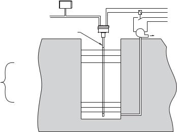
•a stilling well can form the reference electrode.
Where the vessel contents are conductive:
•the interface between the contents and the electrode insulation acts as the reference electrode
•a connection from the vessel contents to the instrument ground is required
•a stilling well can provide a means of connecting the contents to the instrument ground.
The stilling well
The stilling well is a metal tube concentric with the electrode, with vent openings to facilitate level equalization. Its diameter is somewhat larger than that of the electrode, depending on the application. The stilling well can either be integral to the SITRANS LC 500, or it may be part of the tank1.
The SITRANS LC 500 electrode
The SITRANS LC 500 electrode, comprising a measurement section and an active shield section, is the primary sensor of the system. It supplies the electrical capacitance value of the measurement section relative to the environment (tank wall or stilling well).
The SITRANS LC 500 patented Active-Shield Technology electrically isolates the measurement section and prevents any non-measurement capacitance from interfering with the measurement. (Capacitance changes could result from uncontrolled variations occurring in the connection cable, process connection, and non-active parts of the probe). This results in a better ratio of initial capacitance to total capacitance, resulting in higher accuracy.
1. The tank wall, or the stilling well if it is part of the tank, must be grounded.
Page 10 |
SITRANS LC 500 – INSTRUCTION MANUAL |
7ML19985GE01 |

|
|
|
Conventional Capacitance |
|||||||||||||||
|
|
|
|
|
Measurement |
|||||||||||||
|
|
R |
= (C1 + C2 + C3) + Ca |
|||||||||||||||
|
|
|
|
|
|
|||||||||||||
|
|
|
|
(C1 + C2 + C3) + Ca + Cm |
||||||||||||||
R |
= |
Ratio between initial |
|
|
|
|
|
|
|
|
|
|
|
|
|
|
|
|
|
|
|
|
|
|
|
|
|
|
|
|
|
|
|
|
|||
|
|
capacitance and total |
|
|
Measuring- |
|
|
|||||||||||
|
|
capacitance |
|
|
|
Circuit |
|
|
||||||||||
Ca |
= |
Initial capacitance (air) |
|
|
|
|
|
|
|
|
|
|
|
|
|
|
|
|
Cm |
= Capacitance Increase |
|
|
|
|
|
|
|
|
|
|
|
|
|
|
|
|
|
|
C1 |
|
|
|
|
|
|
|
|
|
|
|
|
|
||||
|
|
|
|
|
|
|
|
|
|
|
|
|
|
|||||
|
|
(product) |
|
|
|
|
|
|
||||||||||
C1 |
= Capacitance connection |
|
C2 |
|
|
|
|
|
|
|
|
|
|
|
|
|
||
|
|
point |
|
C3 |
|
|
|
|
|
|
|
|
|
|
|
|
|
|
C2 |
= Capacitance connection |
|
|
|
|
|
|
|||||||||||
|
|
|
|
|
|
|
|
|
|
|
|
|
|
|
|
|||
|
|
|
|
|
|
|
|
|
|
|
|
|
|
|
|
|||
|
|
cable |
|
|
|
|
|
|
|
|
|
|
|
|
|
Ca |
||
C3 |
= |
Capacitance Process |
|
|
|
|
|
|
|
|
|
|
|
|
|
Cm |
||
|
|
connection (includes active |
|
|
|
|
|
|
|
|
|
|
|
|
|
|
|
|
|
|
part) |
|
|
|
|
|
|
|
|
|
|
|
|
|
|
|
|
|
|
|
|
|
|
|
|
|
|
|
|
|
|
|
|
|
|
|
SITRANS LC 500 with Active Shield
R = Ca
Ca + Cm
Measuring-
Circuit

 Ca
Ca

 Cm
Cm
The measurement is further protected from interference by a buffer, which applies the frequency signal from the measurement section to the active shield section. This effectively eliminates any electrical potential difference between the shield and the measurement section and prevents additional changes in capacitance occurring.
SITRANS
LC 500
active shield |
empty |
full |
|
|
|
tank |
tank |
|
|
active |
|
100% |
|
|
measurement |
|
|
|
|
|
|
|
|
|
section |
|
|
|
|
probe seal |
|
buffer |
|
|
|
frequency |
(f) ≈ |
K |
|
(inactive) |
|
|||
|
0% |
|
capacitance (C) |
|
|
|
|
The relative lengths of the measurement section and active shield section can be specified to suit a particular application. If the measured range will be short relative to the total length of the electrode, specify a short measurement section. This increases the achievable resolution of the measurement, since any change in level will be greater relative to the length of the measurement section.
Application & Operation
7ML19985GE01 |
SITRANS LC 500 – INSTRUCTION MANUAL |
Page 11 |

Operation & Application
The entire SITRANS LC 500 transmitter is potted in epoxy resin as part of the intrinsic safety protection. The potting also protects the electronics against mechanical vibration and moisture influences.
The transmitter is connected to the electrode by a mini coaxial cable, and grounded to a connection point inside the enclosure. The external ground lug on the enclosure provides a means of connecting the instrument system ground to a grounded tank or stilling well1. (For more detailed information on grounding requirements, please see Grounding Examples, page 28.)
The measuring range of the SITRANS LC 500 is 3300 pF (1.0 pF 10–12F).
Note: For safety purposes, and to ensure reliable measurement signals, the external ground lug provided on the SITRANS LC 500 enclosure must be firmly connected by an adequate cable to the grounded vessel or stilling well1.
Application: SITRANS LC 500
The SITRANS LC 500 provides an analog and a solid-state output. The analog output can be either a continuous signal proportional to the reading, or in 2-state mode, a mA signal operating according to NAMUR recommendations for fault signalling2.
0% (LRV) and 100% (URV) can be set anywhere within the measurement range.
1.The loop current provides either: a. an analog signal:
•a reading proportional to level (PV) under normal conditions
•an out-of-limits display, ‘ooL’, alternating with PV, in fault conditions (if the process level exceeds the limit settings [USL] or [LSL])
or:
b.in 2-state mode, provides a mA output:
•4 mA or 20 mA output for 0% and 100%, under normal conditions
•a 3.6 or 22 mA output in fault conditions (when 2-state fault signalling [menu 08] is enabled, if the process level exceeds the limit settings [USL or LSL])
2.The solid-state output can be set to ‘contact open’ or ‘contact closed’, relative to a covered probe: it can be wired to an external relay and used to activate an external alarm or a pump via an auxiliary power circuit. It can be activated under normal conditions by the threshold settings, or Fault signalling can be enabled at menu 18.
1.Where the stilling well is welded to the tank.
2.See page 93 for detailed examples.
Page 12 |
SITRANS LC 500 – INSTRUCTION MANUAL |
7ML19985GE01 |
solidstate switch output or 2-state
mA output
Indicator - dynamic Primary Variable (units or % of range)
0-100% |
|
auxiliary |
|
|
|
||
|
solid- |
power |
|
|
pump |
||
current loop connection |
state |
||
power |
|||
Active Shield section |
output |
|
|
|
P |
USL URV = 100%
Upper Threshold Setting = % (activation hysteresis)
(deactivation hysteresis) Lower Threshold Setting = %
LRV = 0% LSL
3. |
Upper Threshold Setting and Lower Threshold Setting activate and deactivate the |
|
|
|
|||
|
2-state output, and/or the solid-state output: the settings can be modified to adjust |
Operation |
|
|
2-state output can be modified by Upper and/or Lower Threshold delays. |
||
|
the hysteresis (the window within which the probe is considered ‘covered’). |
|
|
4. |
The speed of response to activation and deactivation of the solid-state and/or |
|
|
5. |
The PV reading can be stabilized if necessary by applying Damping. |
& |
|
Application |
|||
6. |
Overfill or underfill protection can be set in the absence of those conditions by |
||
|
|||
|
applying the Delta Range Setting. |
|
|
7. |
Analog Fault Signalling (menu 08) and Digital Fault Signalling (menu 18) take |
|
|
|
precedence over the threshold settings (menus 07 and 17). |
|
Level Measurement
The continuous 4-20 or 20-4 mA signal is proportional to the surface level of the product, with an accuracy of 0.1% of the actual measurement (for example, 1mm/m).
Typically, Lower Range Value (LRV - 0%) is set to 4 mA and Upper Range Value (URV - 100%) is set to 20 mA: but the reverse is possible if required. The measurement takes place anywhere within that range. The LCD displays the value as mA, or pF, or percent, depending on the setting for the transmitter variable (TV). If you are using HART, you have the option to define the units.
7ML19985GE01 |
SITRANS LC 500 – INSTRUCTION MANUAL |
Page 13 |

Operation & Application
Interface Measurement
The capacitance of the electrode system is dependent on the dielectric constant of the product surrounding the probe. By comparing the capacitances resulting from different products with different dielectric constants, it is possible to determine which product is surrounding the probe.
For miscible products:
Contamination of one product by another can be measured:
100% product A |
4 mA |
100% product B |
20 mA |
Values in between 4 and 20 mA represent the ratio of the two products.
For immiscible products:
The interface between two products can be detected by the change in capacitance from one to the other. (See example, For Vessels filled with Oil on page 91.)
Switch action
2-state Switch
The mA output can be used as a 2-state switch set to either 4 or 20 mA. It can be set to go to 4 mA if the probe is covered and 20 mA if the probe is uncovered, or the reverse.
Solid-state Switch
The solid-state output can be set to ‘contact open’ or ‘contact closed’ with a covered probe.
Adjustable hysteresis and time delay
The adjustable hysteresis and time delay settings allow you to adjust the switch action for applications with a lot of surface movement.
Examples:
With a moving surface that fluctuates between 79% and 80%, if the hysteresis is set so that 80 is on and 79 is off, the alarm will constantly alternate between on and off. Either set a time delay, or adjust the hysteresis:
•Set the time delay to 10 seconds (for example): the alarm will be on only after the surface has been at 80% for at least 10 seconds.
•Reset the hysteresis for 70 (for example): the unit will ignore small surface fluctuations between 79 and 80%.
Page 14 |
SITRANS LC 500 – INSTRUCTION MANUAL |
7ML19985GE01 |
Fault Signalling
The SITRANS LC 500 has three fault signalling options:
•via the loop-current
•via HART
•via the solid-state output or solid-state relay.
Via the loop current
When using the mA signal, the SITRANS LC 500 operates according to NAMUR standards1 for fault signalling. The fault/failure signal can be triggered by a failure in the measuring system, such as:
•a checksum error
•a loss of signal caused by a defect in the module
•a short circuit in the sensor
•a process failure if the level exceeds the limit settings and if the unit is programmed to detect this
You can set the Upper and Lower Sensor Limits (menus 0B and 0C) outside the Upper and Lower Range Value settings. In this case, if the process value is outside its nominal range (the span between LRV and URV), but still not at a fault/failure level, the continuous mA output will saturate to 3.8 mA or 20.5 mA. If the process value is outside the Upper or Lower Sensor Limits, this will be registered as a fault/failure.
Depending on the setting chosen for 2-state Fault Signalling (menu 08), the signal will go to either 3.6 mA (F: Lo) or to 22 mA (F:Hi). If you do not use communications to receive status information, we recommend enabling analog fault signalling (menu 08), in order to be warned if a fault or failure occurs. (This feature is disabled by default.)
Via HART
See page 75 for HART Response Code Information. Each HART message is accompanied by a response code. It is then up to the Host to decide what to do in the case of a fault situation. The Host may decide to issue Command 48, which returns more detailed information.
Via the solid-state output
The solid-state switch can be wired up to an external relay, to provide a second level of protection. It can then be used to activate a failure alarm, or a level switch. (See page 93 for details of an application using SITRANS LC 500 as a level indicator, with the two-state output connected to a relay that activates a pump.)
1.See NAMUR recommendation NE 43 on page 107 for more details.
7ML19985GE01 |
SITRANS LC 500 – INSTRUCTION MANUAL |
Page 15 |
Application & Operation

Probe Configuration
SITRANS LC 500: Probe Configuration
The probe (electrode) comprises a measurement section and an active shield section. This electrode connects to the capacitance detector portion of the two-wire loop powered electronic transmitter. The transmitter module is mounted in a powder-coated aluminum enclosure which provides reliable operation in environments with dust, moisture, and high-frequency interference.
SITRANS LC 500 Electrode (Probe) Characteristics
Apply to all general connection configurations:
•The standard SITRANS LC 500 insulated electrode is designed for use in both conducting and non-conducting liquid applications.
•Most electrodes consist of an active shield portion and a measurement portion, which combine to form the complete electrode. (This is not the case for cable electrodes or electrodes with ceramic/enamel insulation.)
•The sum of the active shield length and the measurement length is the total insertion length.
•The active shield design provides continuous immunity from changes in conditions at the top of the vessel where levels of vapors, dust, and condensation may be constantly changing.
•The design of the active shield isolates the starting capacitance of the electrode from the effects of changes in capacitance due to temperature and pressure fluctuations that could cause small changes in the seal geometry.
•The carefully-controlled diameter of the electrodes and insulation produces a linear output over a wide range of capacitance values (1 pF to 3300 pF).
•The end seal is formed as an integral part of the electrode insulation, giving smooth and uniform characteristics (tested to 55 kV).
•Standard single cone seal
active shield
insertion length
measurement
probe portion seal
(inactive)
Page 16 |
SITRANS LC 500 – INSTRUCTION MANUAL |
7ML19985GE01 |

Electrode Assembly
SITRANS LC 500 electrodes come in a variety of formats to provide the necessary characteristics for correct mounting, chemical compatibility, temperature and pressure requirements, and dielectric constant of the medium. The main body of the manual discusses the standard configuration. Other options, with details, are shown in Appendix E:
SITRANS LC 500, alternate versions and application details, page 83.
Process Connections
The standard threaded process connection (S-Series) with PFA insulated electrode, including the active shield, provides good results in all measurement situations within the temperature, pressure, and corrosive capabilities of the materials and seals. This remains true over a wide range of dielectric constants in both non-conducting and conducting materials.
Any standard process connection is available with the SITRANS LC 500, and special versions can be fabricated to match the mounting and application requirements. A wide range of threaded and flanged fittings is available. (Contact your local Siemens Milltronics representative for details, or check our website at: www.siemens-milltronics.com.)
Seal Types
The basic internal seal for the SITRANS LC 500 has a conical-shaped, preloaded pressure/leak resistant construction. Up to three levels of seal protection are implemented depending on the integrity requirements of the application. A single or double cone internal seal forms one or two barriers against leaking, and a third flange face gasket is also available in the D and DD seal construction. The flange face seal also provides a design with no metal wetted parts if required.
Process Connection and Seal Configuration of SITRANS LC 500
Process Connection |
Seal Type |
Seal Description |
|
|
|
Threaded |
S |
Single Cone |
Probe |
|
|
||||
|
|
|
|
|
Welded Flange |
S |
Single Cone |
Configuration |
|
|
|
|
|
|
Solid Machined Flange |
S |
Single Cone |
||
|
|
|||
|
|
|
|
|
|
D |
Single Cone + Teflon flange seal |
|
|
|
|
|
|
|
|
DD |
Double Cone + Teflon flange seal. (Consult your |
|
|
|
local Siemens Milltronics representative.) |
|
||
|
|
|
||
|
|
|
|
|
|
SD |
Double Cone (used for stilling well applications) |
|
|
7ML19985GE01 |
SITRANS LC 500 – INSTRUCTION MANUAL |
Page 17 |

Probe Configuration
Pressure and Temperature Considerations
The maximum temperature and pressure of operation for the standard SITRANS LC 500 level probe is 200°C (392°F) and 200 bar (2900 psi). Please consult the pressure curve on page 18 for qualifications that must be applied to these maximums.
Enamel probes are recommended when the process temperature exceeds 200 °C, and/or in combination with very high pressure.
Note: Consult your Siemens Milltronics representative if the material to be measured may be incompatible with the SITRANS LC 500 materials of construction.
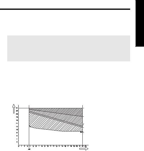
Temperature Versus Pressure Curve for SITRANS LC 500 PFA-insulated Level Probe
As the temperature approaches 75°C (167°F), the maximum pressure must be derated1. When the temperature reaches 200°C (392°F), the maximum pressure is limited to 50 bar (725 psi). This curve is typical for water only. For other, more aggressive chemicals the derating curve will be more severe.
|
|
|
|
|
|
pressure |
|
|
|
|
|
|
|
consult factory when pressure or |
||||
|
|
|
|
|
|
|
|
|
|
|
|
|
temperatures fall within this area |
|||||
|
|
200 bar (2920 psi) |
|
|
|
|
|
|
|
|
|
|
|
|
|
|||
|
|
150 bar (2190 psi) |
|
|
|
|
|
|
|
|
|
|
|
|
|
|||
|
|
|
|
|
|
|
|
|
|
|
|
|
|
|
|
|
|
|
|
|
100 bar (1460 psi) |
|
|
|
|
|
|
|
|
|
|
|
|
|
|
||
|
|
70 bar (1022 psi) |
|
|
|
|
|
|
|
|
|
|
|
|
|
|
||
|
|
50 bar (725 psi) |
|
|
|
|
|
|
|
|
|
|
|
|
|
|
||
|
|
|
–1bar (– |
|
|
|
|
|
70oC |
|
|
|
|
|
||||
|
|
|
|
|
|
|
|
(158 oF) |
|
|
|
|
|
|||||
|
|
|
14.6 psi) |
|
|
|
|
|
|
|
|
temperature |
||||||
|
|
|
|
|
|
|
|
|
|
|
|
|
|
|
|
|
|
|
|
|
|
|
|
|
|
|
|
|
|
|
|
|
|
|
|||
–100 |
oC |
–50 oC |
0 oC |
50 oC |
|
100 oC |
150 oC |
200oC |
||||||||||
(–148 oF) |
(–58 oF) |
(32 oF) |
(122 oF) |
|
(212 oF) |
(302 oF) |
(392 oF) |
|||||||||||
|
|
|
|
|
|
|
|
|
|
|
|
|
|
|
|
|
|
|
Reference Product: Water
Notes:
•For high temperature and pressure ratings for the Enamel probe, please contact your Siemens Milltronics representative.
•For FM / CSA Explosion Proof applications: if the process temperature exceeds 135 oC (275 oF), select process seal type SD,DD,HP or HT.
1. Decreased within the limits specified in the diagram (maximum 200 bar).
Page 18 |
SITRANS LC 500 – INSTRUCTION MANUAL |
7ML19985GE01 |

Non-standard applications
Applications outside the standard capabilities of the S-Series require a different design configuration. These non-standard applications include:
Non-Standard Application |
SITRANS LC 500 Configuration |
|
|
Non-metallic tanks with both conducting |
Use stilling well for second electrode reference. |
and non-conducting liquids. |
|
|
|
Non-conducting liquids in spherical and |
Use a stilling well as linearizer. |
horizontal-cylindrical tanks. |
|
|
|
Highly corrosive materials requiring no |
Use flange mount with D, DD seal version. |
metallic wetted parts. |
|
|
|
Sanitary/food safe applications. |
Use SITRANS LC 500 sanitary version. |
|
|
For more details on alternate configurations, see, Appendix E: SITRANS LC 500, alternate versions and application details on page 83.
Configuration Probe
7ML19985GE01 |
SITRANS LC 500 – INSTRUCTION MANUAL |
Page 19 |

SITRANS LC 500: Installation
Notes:
•Installation shall only be performed by qualified personnel and in accordance with local governing regulations.
•This product is susceptible to electrostatic discharge. Follow proper grounding procedures.
 WARNINGS:
•Disconnect the device before any welding is carried out in the vicinity of the instrument.
•Provide protection when the solid-state switch is activating an external relay to prevent possible switch/relay damage resulting from inductive spikes generated by the relay coil. (See Protection for solidstate switch on page 21 for details.)
Handling Electrodes
 WARNINGS:
• Do not scratch or gouge the PFA electrode insulation since this could reduce the integrity of the insulation and the useful life of the electrode.
• Be careful with an enamel-insulated electrode1.
• Do not damage the insulation jacket on the electrode during shipping, packing, and installation2. Any damage to the electrode can prevent proper performance.
• (ATEX 100): Precautions MUST be taken to avoid ignition due to hazardous electrostatic discharges:
|
|
|
a. Where an isolated probe is used in gas, vapor, or a non- |
|
|
|
|
conductive liquid that is potentially explosive, requiring |
|
|
|
|
apparatus group IIC equipment. |
|
|
|
|
b. Where the probe is used in a potentially explosive dusty |
|
|
|
|
atmosphere. |
|
|
1. |
Normally the enamel insulation is protected by a stilling well, which is part of |
||
|
|
|
||
|
|
|
the design. |
|
|
2. |
Most electrodes use PFA insulation, a very dense and reliable type of Teflon® |
||
Installation |
|
|
that prevents leakage and corrosion of the metal electrode and acts as an |
|
|
insulator when conductive materials are being measured. |
|
||
|
|
|
|
|
|
|
|
|
|
|
Page 20 |
SITRANS LC 500 – INSTRUCTION MANUAL |
7ML19985GE01 |
|
|
||||
Mounting Instructions
The SITRANS LC 500 is easily installed: simply mount the instrument on the process connection of the vessel.
Notes:
•The transmitter is specified for use at temperatures ranging from –40 °C to 85 °C (–40 oF to 185 oF): if your process temperature is outside this range, a standard option is available with a thermal isolator.
•Before mounting the SITRANS LC 500, check to ensure the threads are matching to avoid damaging them.
Protection for solid-state switch
•for dc circuits: connect protection diodes in the correct polarity across the relay coil
•for ac circuits: connect a Voltage Dependent Resistor (VDR) or other ac compatible component (such as zeners and protection diodes in combination) in the correct polarity across the relay coil
Process Cautions
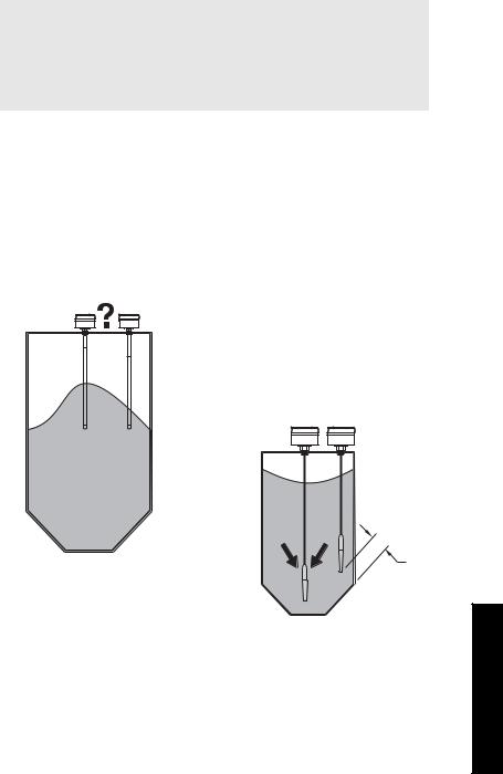
CAUTION: Consider material surface configuration when installing unit.
CAUTIONS:
•With a centrally mounted cable version, take care that the tensile load does not exceed probe or vessel rating
•With a cable version mounted close to the tank wall, take care that the product does not push the cable against the tank wall: a spring can be used as a retainer.
??
500 mm (20”) min.
Installation
7ML19985GE01 |
SITRANS LC 500 – INSTRUCTION MANUAL |
Page 21 |

SITRANS LC 500: Standard Level Version
Available with the following features:
•Threaded flanges, welded flanges, and single-piece flanges
•S series, D series, SD series, DD series, and HP series process seals
•Selections of standard ANSI and DIN flanges
•The most common electrode is insulated with PFA. Enamel (HP seal) is also available (rigid design only).
•Various process connection materials
•Both Rod and Cable versions
See Appendix E: SITRANS LC 500, alternate versions and application details, page 83 onward, for details on dimensions, and for application examples.
Installation
Page 22 |
SITRANS LC 500 – INSTRUCTION MANUAL |
7ML19985GE01 |
Interconnection: SITRANS LC 500
Wiring
Supply
Notes:
•The transmitter is powered by the current loop and needs at least 9.5-13 Volt on the terminals: 9.5 V at 22 mA or 12 V at 3.6 mA.
•The maximum supply is 33 Volt. If the voltage is higher the device will shut down.
•The loop-circuit will withstand voltages up to 250 Vac/Vdc without any damage.
The SITRANS LC 500 uses a switched power supply circuit, which makes the most efficient use of the available power present on the terminals. If the signal current is low, (4mA), the terminal voltage will be high, and if the signal current is high, (20 mA), the terminal voltage may be low, due to all the resistive elements in the loop, such as the barrier and sense resistor.
Voltage drop versus mA for current transmitter operation
|
voltage drop over 250 ohm |
|
measuring resistance |
supply |
voltage drop over 280 ohm in |
barrier |
|
voltage drop over blocking |
|
V- |
diode in barrier |
|
|
|
margin or voltage drop over |
|
instrument cable |
|
operation voltage, |
|
transmitter |
mA
Examples:
•With a 250 Ohm sensing resistor, no barrier and negligible cable resistance, the overall supply voltage should be at least 15.0 V.
•With a 250 Ohm sensing resistor, a barrier of 280 Ohm, and 20 Ohm cable resistance (500 m), the total resistance is 550 Ohm, so the overall supply voltage should be at least 20.5 Volts.
•For a multi-drop application, where the measuring supply is fixed to 4 mA, the voltage on the terminals of the SITRANS LC 500 should be at least 12 Volts.
The loop circuit is completely isolated from the measurement circuit. It is designed so that the internal capacitance and inductance on the terminals are isolated and do not factor in safety calculations.
Interconnection
7ML19985GE01 |
SITRANS LC 500 – INSTRUCTION MANUAL |
Page 23 |

Interconnection
Cable
Notes:
•To maintain reliable transfer of the HART modem signals, the RC1 time constant of the connections should be less than 65 µSec.
•Cable capacitance must also be considered when selecting cable for intrinsically safe installations.
•For output signals (from the SITRANS LC 500), only the cable and barrier resistance are relevant. For input signals the measurement resistance is also relevant.
•Use twisted pair cable, screened as a pair.2
1.RC = Resistance * Capacitance
2.Or, if you use a common screen over a cable containing multiple twisted pairs, do not use other pairs for signals that could interfere with HART signals.
Selecting the correct instrumentation cable
•you need to know the cable length, the barrier type (if applicable), and the measurement resistance
•select a cable that will give you a capacitance time constant of less than 65 µSec
1.Calculate the capacitance for a time constant of 65 µSec, using the following formula:
t = R × C (time constant = Resistance * Capacitance) R is the sum of the load resistor and cable resistance.
C is the sum of the cable capacitance and the capacitances of the connected device/devices.
2.Determine the cable length allowed, by subtracting the capacitance value of the device (or devices) on the loop from the total capacitance, and using the maximum allowable limit of 100 pF per meter (or 1 nF per 10 meters).
Example
1.Calculate the cable capacitance which will give a time constant of 65 µSec:
A twisted pair cable with a conductor cross-section of 1 mm2 (AWG 18 equivalent) has a copper resistance of 73.6 Ohm/km and a capacitance of 100 pF/m (or 1 nF/10m).
For a standard 28 V 280 Ohm barrier and a 250 Ohm measuring resistance, with a 100 meter cable:
Resistance = 280 (barrier) + 250 (sensing device) + 7.36 (cable)= 537.36 t = R × C
C = t ⁄R
65 × 10 – 6 s = 537.36 × C nF
C = (65 × 10 – 6 ⁄537.36)= 121 nF
Page 24 |
SITRANS LC 500 – INSTRUCTION MANUAL |
7ML19985GE01 |
Loading...