

Gebrauchs- und
DE
EN
FR
NL
IT
ES
PT
Istruzioni d’uso
Montageanleitung
Operating and
installation instructions
Mode d’emploi et
notice de montage
Gebruiksaanwijzing en
montagevoorschrift
e per il montaggio
Instrucciones de uso
y de montaje
Instruções de serviçio
e de montagem
䱃‹㔷⁋䈠㜰
LC 85 K 950
LC 86 K 950
⌐တⰣတဣ⌣တဣတဣတေ⌐
LC 957 KB 70
LC 957 KA 70

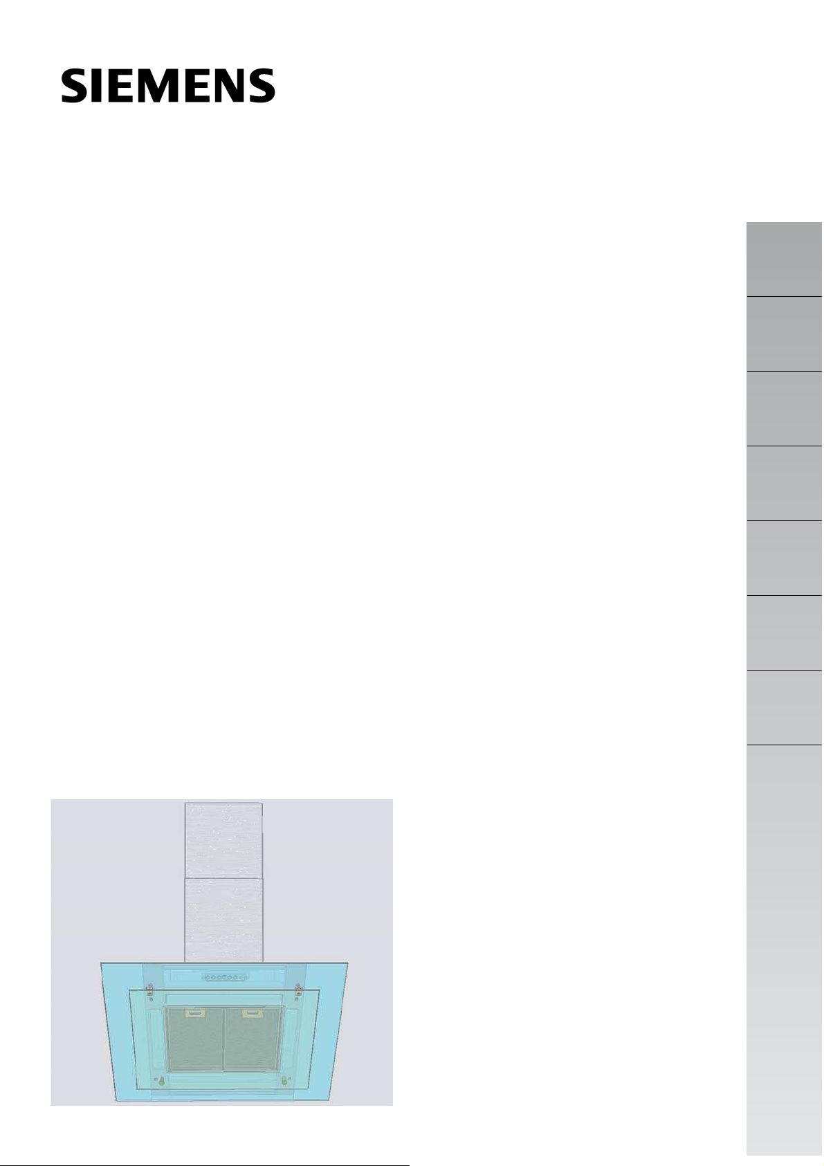
Gerätebeschreibung
Kaminververblendung
Schalter
Licht/Lüfter
Beleuchtung
de
Bei Abluftbetrieb der Dunstabzugshaube und gleichzeitigem Betrieb
schornsteinabhängiger Feuerungen
(wie z.B. Gas-, Öl- oder Kohleheizgeräte,
Gasdurchlauferhitzer, Gasboiler) muss
für ausreichend Zuluft gesorgt werden,
die von der Feuerstätte zur Verbrennung
benötigt wird.
Ein gefahrloser Betrieb ist möglich,
wenn der Unterdruck im Aufstellraum der
Feuerstätte von 4 Pa (0,04 mbar) nicht
überschritten wird.
Dies kann erreicht werden, wenn durch
nicht verschließbare Öffnungen, z.B. in
Türen, Fenstern und in Verbindung mit
Zuluft-/Abluftmauerkasten oder durch
andere techn. Maßnahmen, wie gegenseitige Verriegelung o.ä., die
Verbrennungsluft nachströmen kann.
Kaminverblendung
Fettfilter
- Der Lüfter der Dunstabzugshaube saugt
den Küchendunst an und leitet ihn durch
den Fettfilter ins Freie.
- Der Fettfilter nimmt die fettigen Bestandteile des Küchendunstes auf.
- Die Küche bleibt weitgehend frei von
Fett und Geruch.
Bei nicht ausreichender Zuluft besteht
Vergiftungsgefahr durch zurückgesaugte
Verbrennungsgase.
Ein Zuluft-/Abluftmauerkasten allein
stellt die Einhaltung des Grenzwertes
nicht sicher.
Anmerkung: Bei der Beurteilung muss
immer der gesamte Lüftungsverbund der
Wohnung beachtet werden. Bei Betrieb von
Kochgeräten, z.B. Kochmulde und Gasherd
wird diese Regel nicht angewendet.
Vor dem ersten Benutzen
de
Wichtige Hinweise:
- Diese Gebrauchsanleitung gilt für mehrere Geräte-Ausführungen. Es ist möglich, dass einzelne Ausstattungsmerkmale beschrieben sind, die nicht
auf Ihr Gerät zutreffen.
Diese Dunstabzugshaube entspricht
den einschlägigen Sicherheitsbestimmungen. Reparaturen dürfen nur
von Fachkräften durchgeführt werden.
Durch unsachgemäße Reparaturen
können erhebliche Gefahren für den Benutzer entstehen.
Gas-Kochmulden / Gas-Herde:
Betreiben Sie nicht alle Gas-Kochstellengleichzeitig über längere Zeit (max.
15 Minuten) bei höchster Wärmebelastung, sonst besteht Verbrennungsgefahr bei Berührung der Gehäuseoberflächen bzw. Gefahr der Beschädigung der Dunstabzugshaube. Beim Betrieb der Dunstabzugshaube über einem
Gas-Kochfeld muss bei gleichzeitigem
Betreiben von drei oder mehr GasKochstellen die Haube in der Maximalstufe betrieben werden.
Bevor Sie das neue Gerät benutzen, lesen Sie bitte sorgfältig die Gebrauchsanleitung. Sie enthält wichtige Informationen für Ihre Sicherheit sowie zum Gebrauch und zur Pflege des Gerätes.
- Bewahren Sie die Gebrauchs- und
Montageanleitung ggf. für einen Nachbesitzer gut auf.
- Dieses Gerät ist entsprechend der europäischen Richtlinie 2002/96/EG über
Elektro- und Elektronik-Altgeräte (waste
electrical and electronic equipment –
WEEE) gekennzeichnet. Die Richtlinie
gibt den Rahmen für eine EU-weit gültige Rücknahme und Verwertung der Altgeräte vor.
Sicherheitshinweise
Unter der Dunstabzugshaube nicht flambieren. Brandgefahr am Fettfilter durch aufsteigende Flammen.
Die Kochstellen müssen immer mit Kochgeschirr abgedeckt sein.
Über einer Feuerstätte für feste Brennstoffe
(Kohle, Holz und dgl.) ist der Betrieb der
Dunstabzugshaube nur bedingt gestattet
(siehe Montageanleitung).
Die Dunstabzugshaube nur mit eingesetzten Lampen betreiben.
Defekte Lampen sollten sofort ersetzt werden, um Überlastung der restlichen Lampen zu vermeiden.
Die Dunstabzugshaube nie ohne Fettfilterbetreiben.
Überhitzte Fette oder Öle können sich leicht
entzünden. Darum Speisen mit Fetten oder
Ölen, z.B. Pommes frites, nur unter Aufsichtzubereiten.
Ist das Gerät beschädigt, dürfen Sie es nicht
in Betrieb nehmen.
Anschluss und Inbetriebnahme dürfen nur
von einem Fachmann durchgeführt werden.
Wenn die Anschlussleitung dieses Gerätes
beschädigt wird, muss sie durch den Hersteller oder seinen Kundendienst oder eine
ähnlich qualifizierte Person ersetzt werden,
um Gefährdung zu vermeiden.
Verpackungsmaterial ordnungsgemäß entsorgen (siehe Montageanleitung).
Diese Dunstabzugshaube ist nur für den
Betrieb in Haushalten bestimmt.
Die Dunstabzugshaube vor der ersten Inbetriebnahme sorgfältig reinigen.
Keine Gegenstände auf der Dunstabzugshaube abstellen.
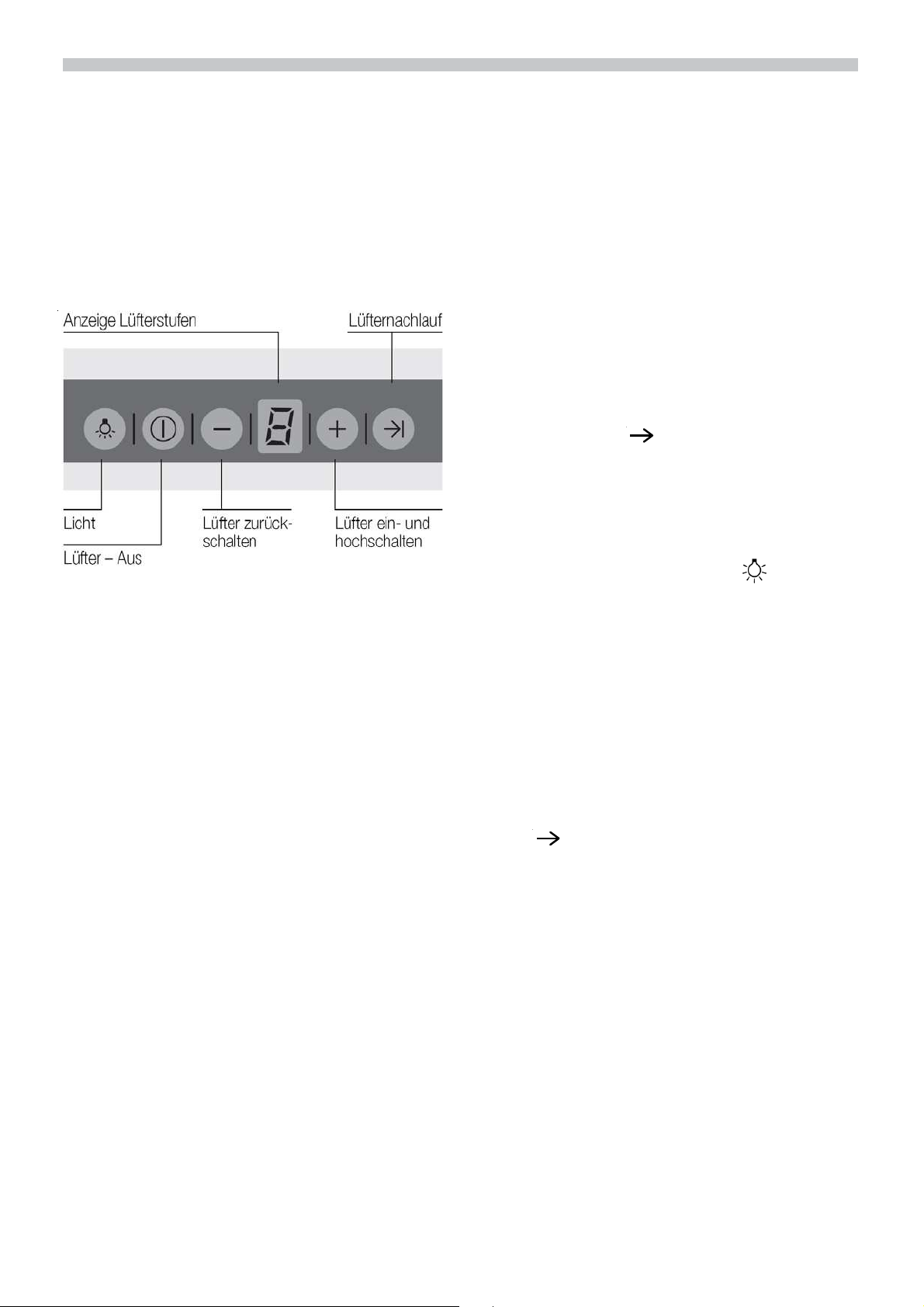
Bedienen der Dunstabzugshaube
de
Der Küchendunst wird am wirkungsvollsten beseitigt durch:
Einschalten der Dunstabzugshaube bei
Kochbeginn.
Ausschalten der Dunstabzugshaube erst einige Minuten nach Kochende.
Signalton:
Beim Drücken einer Taste ertönt zur Bestätigung ein Signalton.
Ausschalten des Signaltons:
Drücken Sie gleichzeitig die Tasten
0und + bis nach ca. 3 Sekunden ein Signal ertönt.
Einschalten des Signaltons:
Wiederholen Sie den Vorgang.
Einschalten des Lüfters:
Drücken Sie die Taste +
Einstellen der gewünschten Lüfterstufe:
Drücken Sie die Taste +. Der Lüfter schaltet
eine Stufe höher.
Drücken Sie die Taste –.Der Lüfter schaltet
eine Stufe zurück.
Ausschalten des Lüfters:
Drücken Sie die Taste 0. Die Anzeige 0 erlischt nach kurzer Zeit.
Drücken Sie die Taste – so oft, bis der Lüfter
ausschaltet. Die Anzeige 0 erlischt nach kur-
zer Zeit.
Intensivstufe:
Durch die Intensivstufe wird die höchste
Leistung erreicht. Sie wird kurzzeitig benötigt.
Drücken Sie die Taste + so oft, bis die Anzeige
Wird die Intensivstufe nicht von Hand ausgeschaltet, schaltet der Lüfter nach 10 Minuten selbsttätig auf Stufe 2 zurück.
Lüfternachlauf:
Drücken Sie die
Der Lüfter läuft 10 Minuten in der Stufe 1
Dabei blinkt in der Anzeige ein Punkt.
Danach schaltet der Lüfter selbsttätig aus.
Beleuchtung:
Drücken Sie kurz die Taste
und Ausschalten.
Die Beleuchtung kann zu jeder Zeit verwendet werden, auch wenn der Lüfter ausgeschaltet ist.
Automatisches Einschalten der Beleuchtung, z.B. über eine Zeitschaltuhr:
Lüfter und Beleuchtung müssen ausgeschaltet sein.
Einschalten:
Drücken Sie gleichzeitig die Tasten
– und
Nach ca. 3 Sekunden schaltet sich zur Bestätigung die Beleuchtung ein.
Ausschalten:
Wiederholen Sie den Vorgang bei eingeschalteter Beleuchtung.
Nach ca. 3 Sekunden schaltet sich zur Bestätigung die Beleuchtung aus.
P leuchtet.
I
I
zum Ein-
Oder:
Filter und Wartung
de
Fettfilter:
Zur Aufnahme der fettigen Bestandteile des
Küchendunstes sind Metall-Fettfilter eingesetzt.
Die Filtermatten bestehen aus
unbrennbarem Metall.
Achtung:
Bei zunehmender Sättigung mit fetthaltigen
Rückständen erhöht sich die Entflammbarkeit und die Funktion der Dunstabzugshaube kann beeinträchtigt werden.
Wichtig:
Durch rechtzeitiges Reinigen der Metall-Fettfilter wird der Brandgefahr vorgebeugt, die
durch Hitzestau beim Frittieren oder Braten
entstehen kann.
Sättigungsanzeige:
Bei Sättigung der Fettfilter ertönt nach dem
Ausschalten des Lüfters für 6 Sekunden ein
Signal und die Anzeige
Spätestens dann sollten die Fettfilter gereinigt werden.
≡≡≡≡
leuchtet.
≡≡≡≡
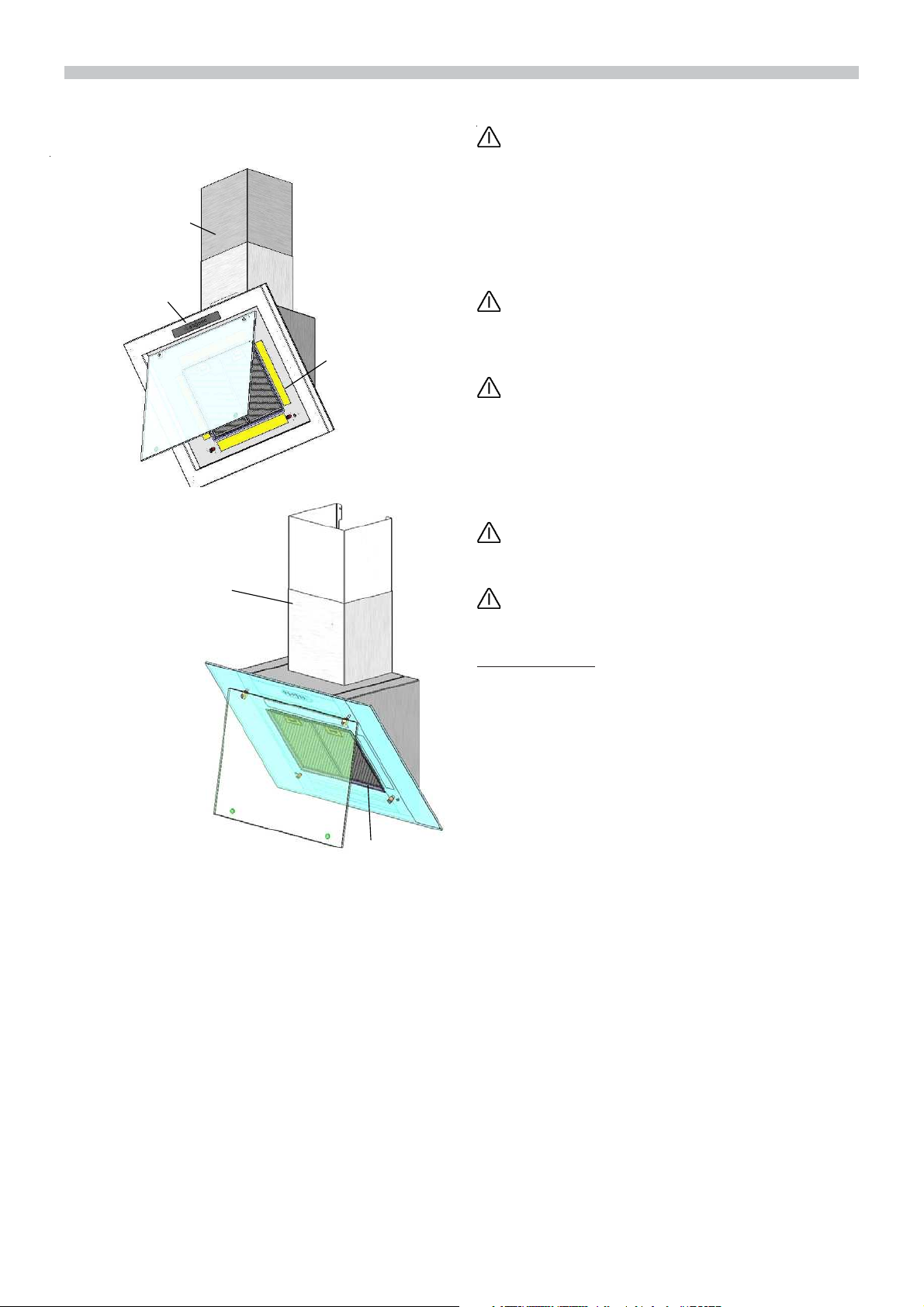
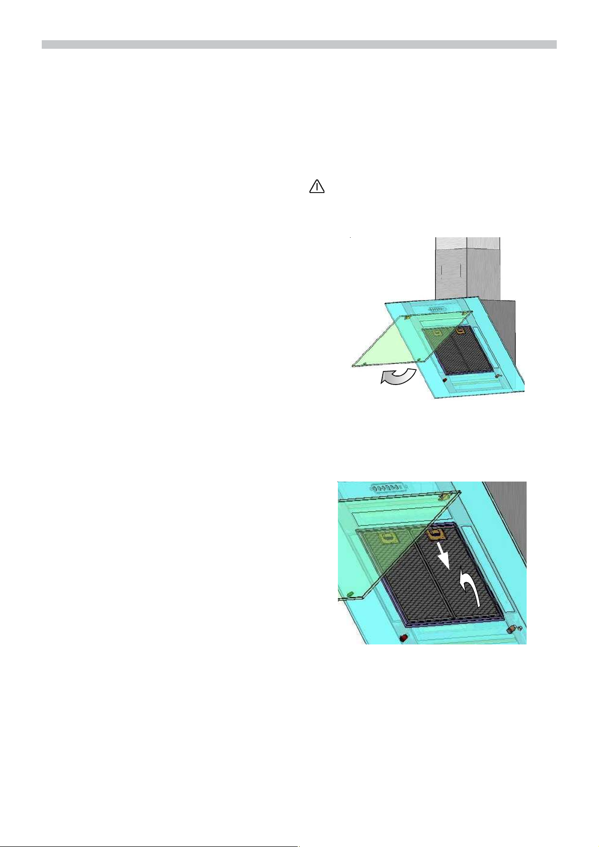
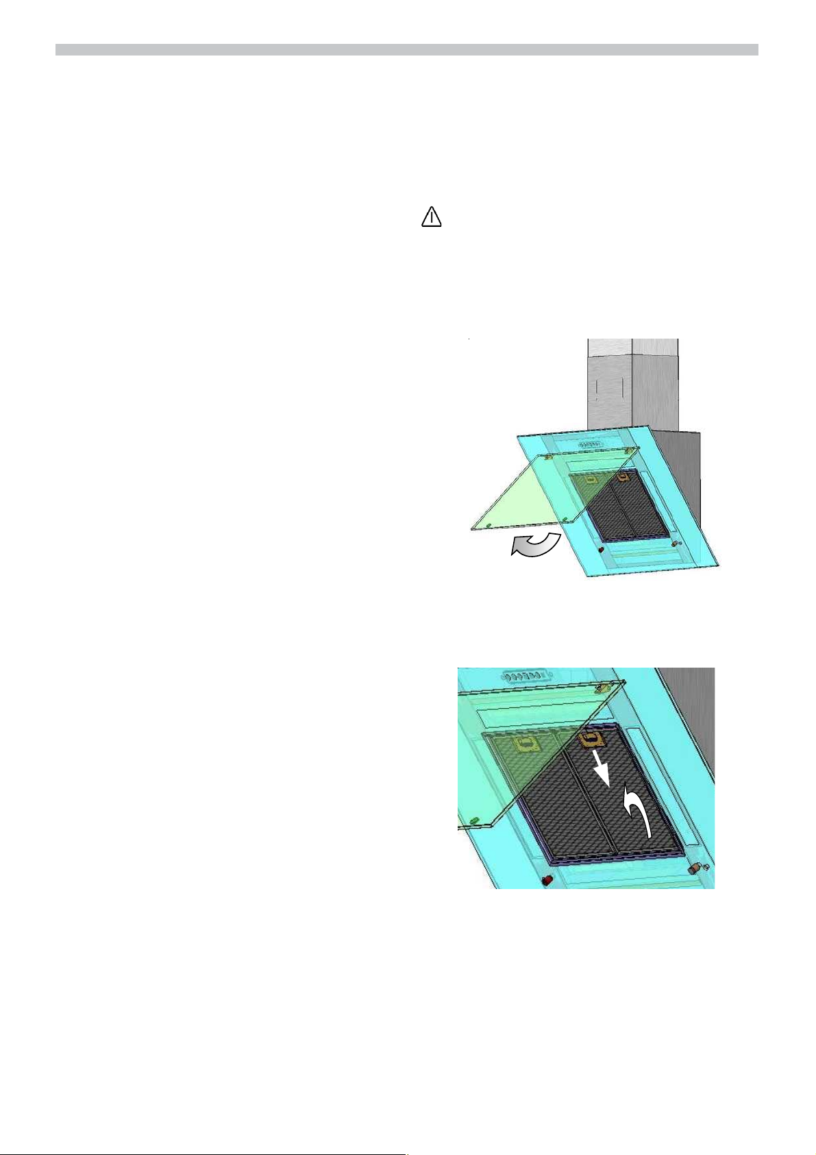
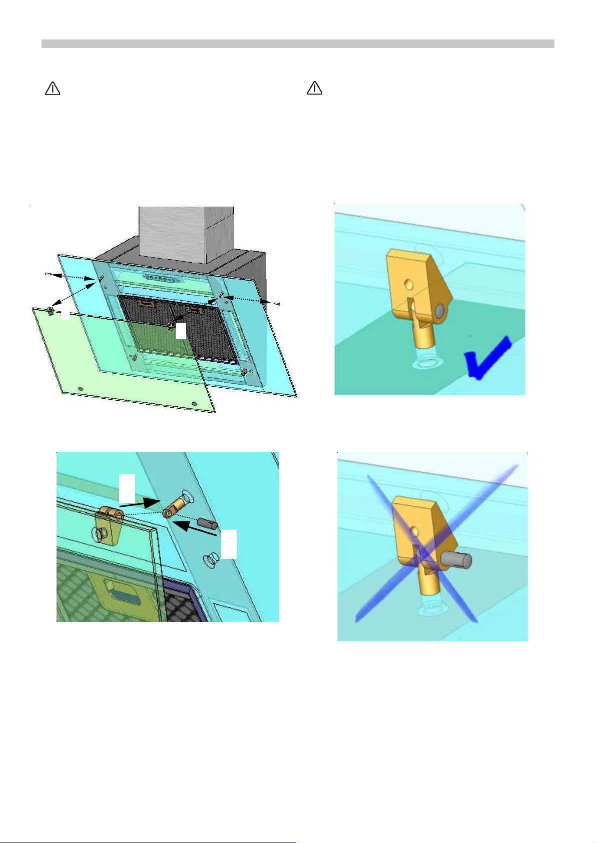
Aus- und Einbauen der Metall-Fettfilter:
Wechseln Sie die Fettfilter nur bei geöffnetter
Frontscheibe.
1. Drücken Sie die Rasten der vorderen
Fettfilter und klappen Sie die Fettfilter ab.
Bitte die Scheibe maximal um 90° abschwenken, da sonst die Glasscheibe
zerstört werden kann.
max 90°
Reinigen der Metall-Fettfilter:
Bei normalem Betrieb (täglich 1 bis 2 Stunden) müssen die Metall-Fettfilter 1x im Monat gereinigt werden.
Das Reinigen kann in der Geschirrspülmaschine erfolgen. Dabei ist eine leichte Verfärbung möglich.
Der Filter muss locker in der Geschirrspülmaschine liegen. Er darf nicht eingeklemmt
sein.
Wichtig:
Stark gesättigte Metall-Fettfilter nicht zusammen mit Geschirr reinigen.
Beim Reinigen von Hand, die Fettfilter in
heißer Spüllauge einweichen. Keine aggressiven, säure- oder laugenhaltigen
Reiniger verwenden. Danach abbürsten, gut
ausspülen und abtropfen lassen.
2. Drücken Sie die Rasten der hinteren Fettfilter und klappen Sie die Fettfilter ab.
2
3. Reinigen Sie die Fettfilter.
4. Setzen Sie die gereinigten Fettfilter
wieder ein.
5. Löschen Sie die Anzeige
cken der Taste 0.
durch Drü-
≡≡≡≡
de
2
Reinigen und Pflegen
Dunstabzugshaube durch Ziehen des
Netzsteckers bzw. Ausschalten der Sicherung stromlos machen.
Dunstabzugshaube nicht mit kratzenden
Schwämmen und nicht mit sand-, soda-,
säure- oder chloridhaltigen Putzmitteln reinigen!
Zum Reinigen der Dunstabzugshaubeheiße Spüllauge oder mildes Fensterputzmittel verwenden.
Kratzen Sie angetrocknete Verschmutzung
nicht ab, sondern weichen Sie diese mit einem feuchten Tuch auf.
Beim Reinigen der Fettfilter die zugänglichen
Gehäuseteile von abgelagertem Fett reinigen. Dadurch wird der Brandgefahrvorgebeugt und die optimale Funktion bleibt
erhalten.
Hinweis: Alkohol (Spiritus) nicht auf
Kunststoffflächen anwenden, es könnten
matte Stellen entstehen.
Vorsicht! Küche ausreichend belüften, keine offene Flamme.
Die Bedientasten nur mit milder Spüllauge
und einem weichen, feuchten Tuch reinigen.
Keinen Edelstahlreiniger für die Bedientasten verwenden.
Edelstahloberflächen:
Verwenden Sie einen milden nichtscheuernden Edelstahlreiniger.
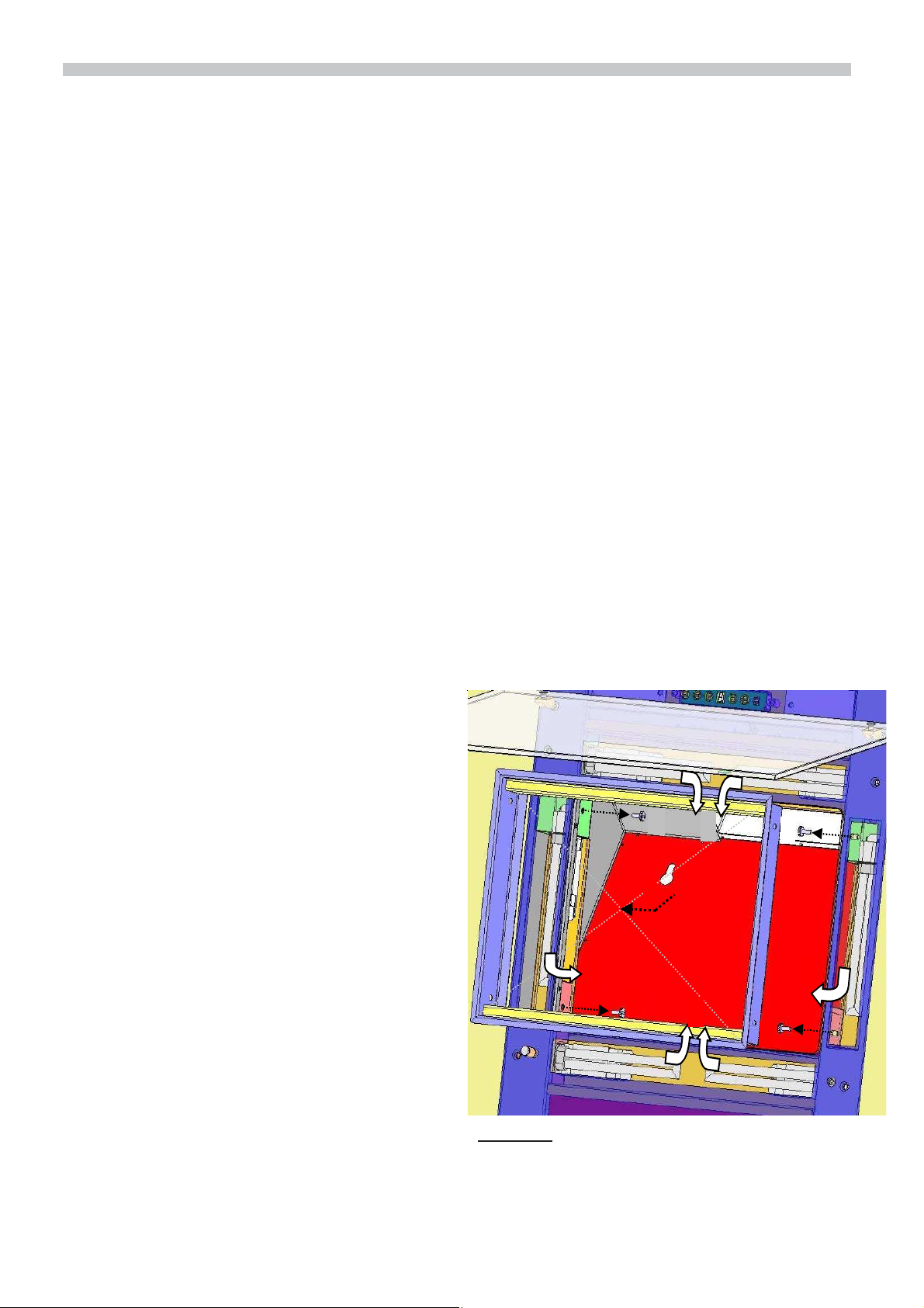
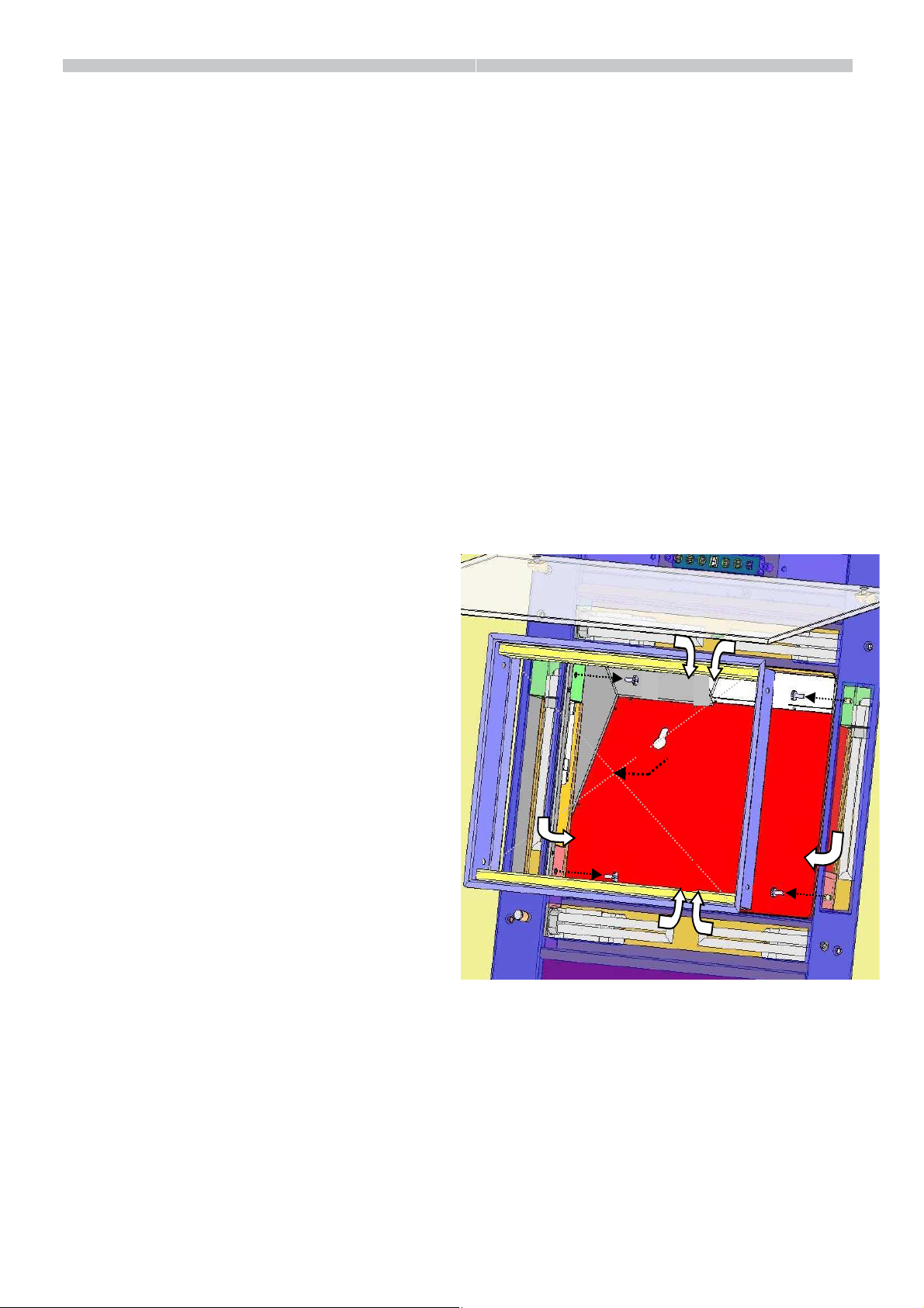
Auswechseln der Lampen
1. Schalten Sie die Dunstabzugshaube
aus und machen Sie durch Ziehen des
Netzsteckers oder Ausschalten der
Sicherung die Dunstabzugshaube
stromlos.
2. Entfernen sie zunächst die Fettfilter (sie-
he Kapitel Fettfilter und Wartung)
3. Schrauben Sie den Fettfilterrahmen, mittels dem beigelegten Innensechskantschlüssel (SW3 mm), durch lösen
der Linsenkopfschrauben ab. Vorsicht
beim Lösen der letzten Schraube, da der
Fettfilterrahmen auf das Kochfeld fallen
kann.
4. Tauschen Sie das defekte Leuchtmittel
(Osram Dulux S 11W) nun durch vorsichtiges Ziehen aus der Fassung heraus.
Bitte verwenden Sie die Haube nur mit
eingestecktem Leuchtmittel.
5. Führen Sie nun den Filterrahmen wieder
ein und schrauben Sie die 4 Linsenkopfschrauben mit dem Innensechskantschlüssel fest.
6. Stellen Sie durch Einstecken des Netzsteckers oder durch Einschalten der Sicherung die Stromversorgung wieder
her.
Reinigen Sie nur in Schliffrichtung.
Wir empfehlen unseren Edelstahlreiniger
Nr. 461731. Bestell-Adresse siehe beiliegendes Service-Heft.
Aluminium-, Lack- und Kunststoffoberflächen:
Keine trockenen Tücher verwenden.
Verwenden Sie ein mildes Fenster-
reinigungsmittel.
Keine aggressiven, säure- oder laugen-
haltigen Reiniger verwenden.
1
3
1
3
3
1
3
1
Hinweis: Sollte die Beleuchtung nicht funk-
tionieren, kontrollieren Sie, ob die Lampen richtig eingesteckt sind.

Störungen Vor der Montage
de
Wenn in der Anzeige ein
Siehe Abschnitt „Filter und Wartung“.
Wenn sich die Dunstabzugshaube nicht
bedienen lässt:
Für ca. 1 Minute die Dunstabzugshaube
durch Ziehen des Netzsteckers bzw. Ausschalten der Sicherung stromlos machen.
Danach neu einschalten.
Bei eventuellen Rückfragen oder Störungen,
Kundendienst anrufen.
(Siehe Kundendienststellenverzeichnis).
Bei Anruf bitte folgende Gerätedaten bereit-
halten:
AB-Nr. FD
Tragen Sie die Nummern in obige Felder
ein. Die Nummern sind auf dem Typenschild, nach Abnahme der Fettfilter, im Innenraum der Dunstabzugshaube zu finden.
Für Beanstandungen die auf Planung und
Ausführung der Rohrstrecke zurückzuführen sind, übernimmt der Hersteller der
Dunstabzugshauben keine Gewährleistung.
oder [ erscheint:
≡≡≡≡
Wichtige Hinweise
Altgeräte sind kein wertloser Abfall.
Durch umweltgerechte Entsorgung können
wertvolle Rohstoffe wiedergewonnen werden. Bevor Sie das Altgerät entsorgen, machen Sie es unbrauchbar.
Ihr neues Gerät wurde auf dem Weg zu Ihnen durch die Verpackung geschützt. Alle
eingesetzten Materialien sind umweltverträglich und wieder verwertbar. Bitte helfen Sie mit und entsorgen Sie die Verpackung umweltgerecht.
Über aktuelle Entsorgungswege informieren Sie sich bitte bei Ihrem Fachhändler
oder bei Ihrer Gemeindeverwaltung.
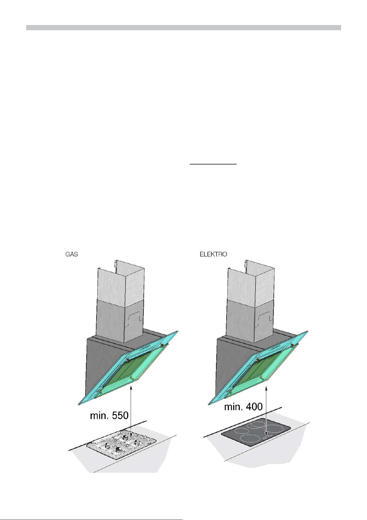
Die Dunstabzugshaube immer über der
Mitte der Kochstellen anbringen.
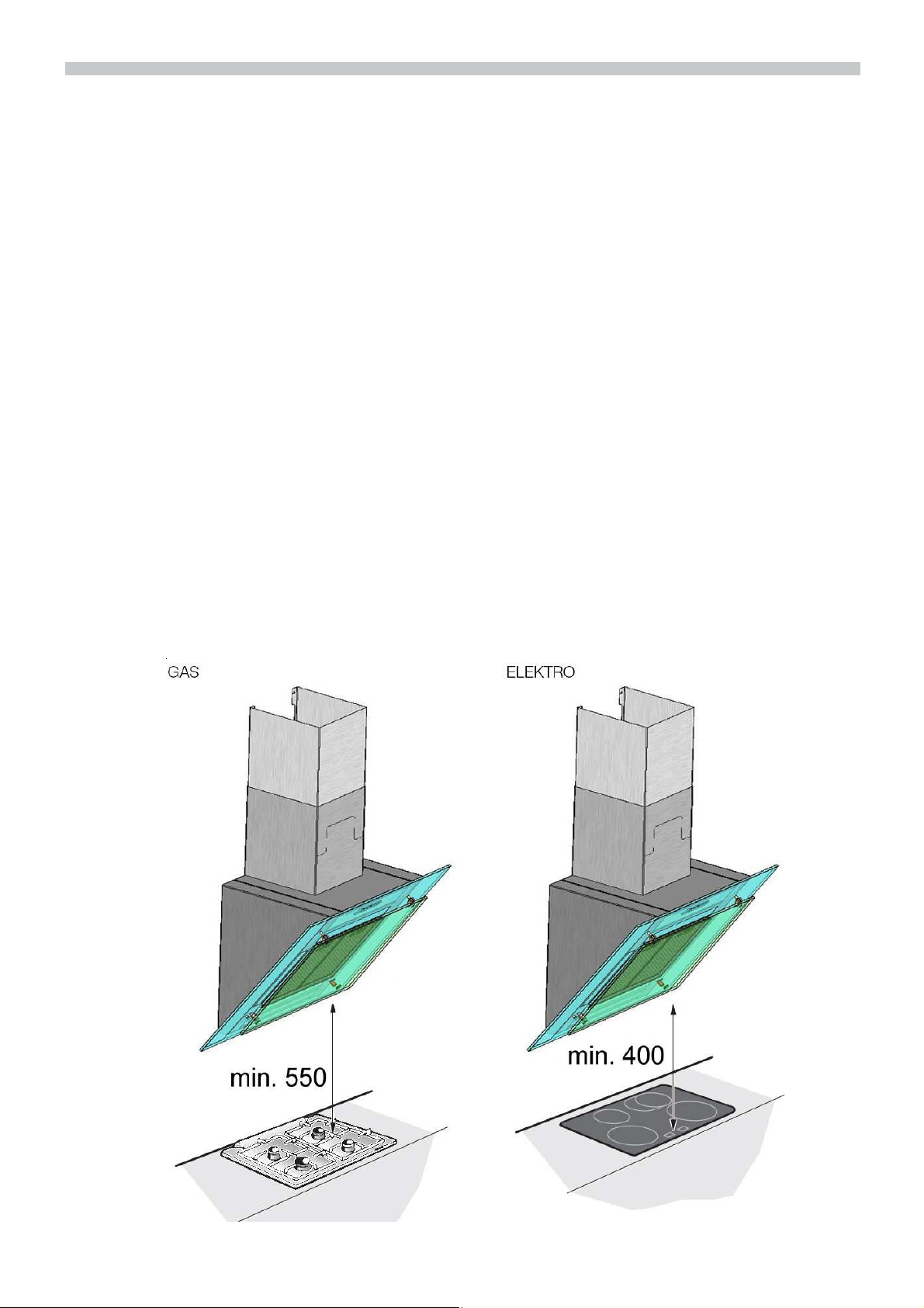
Mindestabstand zwischen Elektrokochstellen
und Unterkante der Dunstabzugshaube: 400 mm
Über einer Feuerstätte für feste Brennstoffe, von der eine Brandgefahr(z.B. Funkenflug) ausgehen kann, ist die Montage der
Dunstabzugshaube nur dann zulässig,
wenn die Feuerstätte eine geschlossene
nicht abnehmbare Abdeckung hat und die
länderspezifischen Vorschriften eingehalten werden. Diese Einschränkung gilt
nicht für Gas-Herde und Gas-Mulden.
Je kleiner der Abstand zwischen Dunstabzugshaube und Kochstellen desto größer
ist die Möglichkeit, dass sich durch aufsteigenden Wasserdampf unten an der Dunstabzugshaube Tropfen bilden können.
Zusätzliche Hinweise bei Gas-Kochgeräten:
Bei der Montage von Gaskochstellen sind
die national einschlägigen gesetzlichen Bestimmungen (z.B. in Deutschland: Technische Regeln Gasinstallation TRGI) zu beachten.
Es müssen die jeweils gültigen Einbauvorschriften und die Einbauhinweise der GasGerätehersteller beachtet werden.
Die Dunstabzugshaube darf nur an einer
Seite neben einem Hochschrank oder einer hohen Wand eingebaut werden. Abstand mind. 50 mm.
Mindestabstand bei Gas-Kochstellen zwischen Oberkante Topfträger und Unterkante der Dunstabzugshaube: 550 mm,
Vor der Montage
de
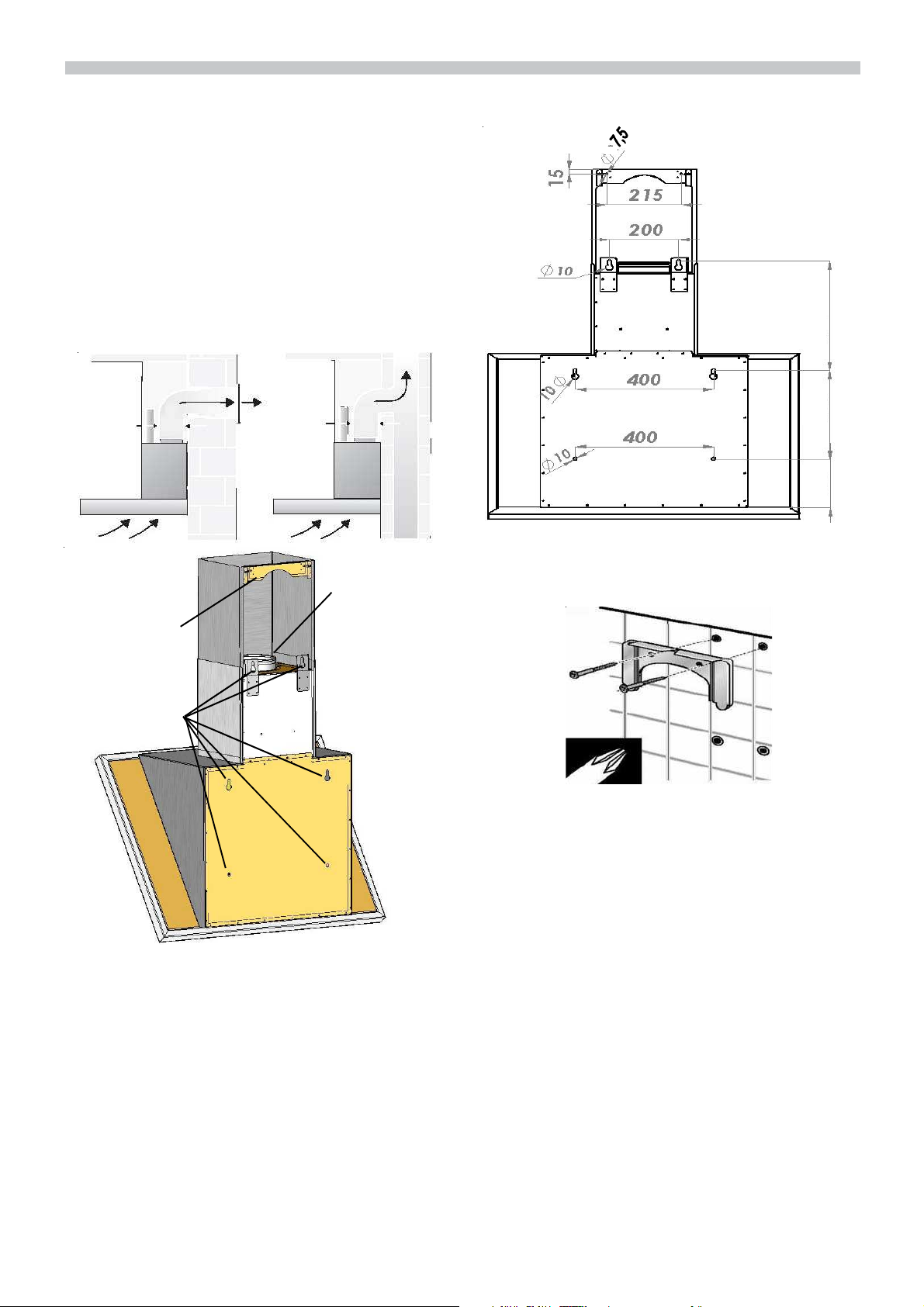
Die Abluft wird über einen Lüftungsschacht nach oben, oder direkt durch die
Außenwand ins Freie geleitet. Die Abluft
darf weder in einen in Betriebbefindlichen
Rauch- oder Abgaskamin noch in einen
Schacht, welcher der Entlüftung von Aufstellungsräumen von Feuerstätten dient,
abgegeben werden.
Bei der Ableitung von Abluft sind die behördlichen und gesetzlichen Vorschriften (z.B.
Landesbauordnungen) zu beachten.
Bei Abführung der Luft in nicht in Betriebbefindliche Rauch- oder Abgaskamine ist
die Zustimmung des zuständigen
Schornsteinfegermeisters einzuholen.
Bei Abluftbetrieb der Dunstabzugshaube
und gleichzeitigem Betrieb schornsteinabhängiger Feuerungen (wie z.B. Gas-, Öloder Kohleheizgeräte, Gasdurchlauferhitzer,
Gasboiler) muss für ausreichend Zuluft gesorgt werden die von der Feuerstätte zur Verbrennung benötigt wird. Ein gefahrloser
Betrieb ist möglich, wenn der Unterdruck im
Aufstellraum der Feuerstätte von 4 Pa (0,04
mbar) nicht überschritten wird. Dies kann
erreicht werden, wenn durch nicht verschließbare Öffnungen, z.B. in Türen, Fenstern und in Verbindung mit Zuluft-/Abluftmauerkasten oder durch andere technische
Maßnahmen, wie gegenseitige Verriegelung
o.ä., die Verbrennungsluft nachströmen
kann.
Bei nicht ausreichender Zuluft besteht
Vergiftungsgefahr durch zurückgesaugte
Verbrennungsgase.
Ein Zuluft-/Abluftmauerkasten allein stellt
die Einhaltung des Grenzwertes nicht sicher.
Anmerkung: Bei der Beurteilung muss
immer der gesamte Lüftungsverbund der
Wohnung beachtet werden. Bei Betrieb von
Kochgeräten, z.B. Kochmulde und Gasherd
wird diese Regel nicht angewendet.
Optimale Leistung der
Dunstabzugshaube:
Kurzes, glattes Abluftrohr. Möglichst wenig
Rohrbögen. Möglichst große Rohrdurchmesser und große Rohrbögen.

Vor der Montage
de
Der Einsatz von langen, rauhen Abluftrohren, vielen Rohrbögen oder kleineren
Rohrdurchmessern führt zu einer Abweichung von der optimalen Luftleistung und
gleichzeitig zu einer Geräuscherhöhung.
Für Beanstandungen die auf Planung und
Ausführung der Rohrstrecke zurückzuführen sind, übernimmt der Hersteller der
Dunstabzugshauben keine Gewährleistung.
Rundrohre: Wir empfehlen Innendurch-
messer 150 mm oder größer,
Flachkanäle müssen mind. einen gleich-
wertigen Innenquerschnitt wie Rundrohre
haben.
Sie sollten keine scharfen Umlenkungen
haben.
Bei Abluftbetrieb für ausreichend Zuluft sorgen.
Wenn die Anschlussleitung dieses Gerätes
beschädigt wird, muss sie durch den Hersteller oder seinen Kundendienst oder eine
ähnlich qualifizierte Person ersetzt werden,
um Gefährdung zu vermeiden.
Diese Dunstabzugshaube entspricht den
EG-Funkentstörbestimmungen.
Einbauen
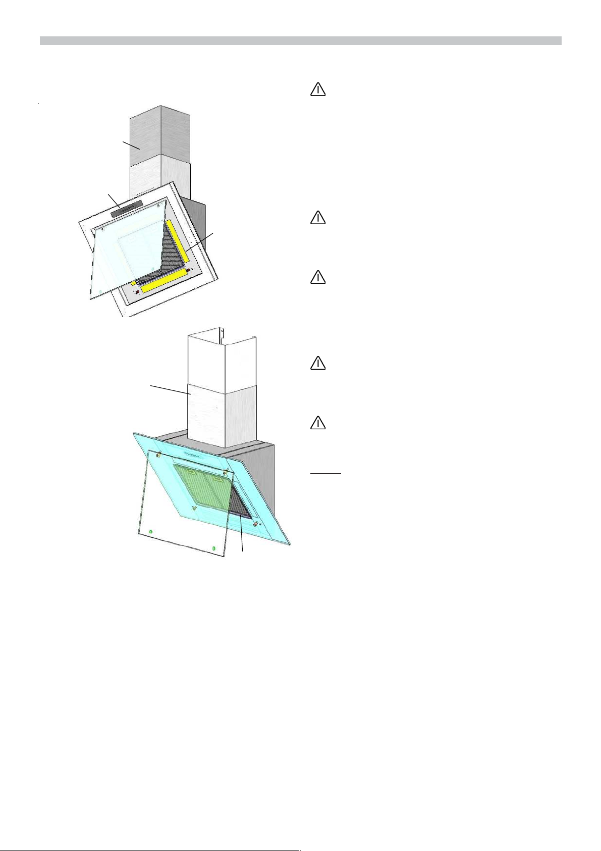
Um Transportbeschädigungen vorzubeugen ist die Frontglasscheibe getrennt vom
Haubenkörper verpackt und muss nach dem
auspacken mit dem Haubenkörper verbunden werden (siehe nachfolgende Zeichnung).
Elektrischer Anschluss
Die Dunstabzugshaubedarf nur an eine vorschriftsmäßig installierte Schutzkontaktsteckdose angeschlossen werden. Die
Schutzkontaktsteckdose möglichst direkt
hinter der Kaminverblendung anbringen.
Elektrische Daten:
Sie sind auf dem Typenschild nach Abnahme der Filterrahmen – im Innenraum des
Gerätes – zu finden.
Bei Reparaturen die Dunstabzugshaube
generell stromlos machen.
Bei erforderlichem Festanschluss:
Die Dunstabzugshaube darf in jedem Fall
nur durch einen beim zuständigen Elektrizitäts-Versorgungsunternehmen eingetragenen Elektro-Installateur angeschlossen
werden.
Installationsseitig ist eine Trennvorrichtung
vorzusehen. Als Trennvorrichtung gelten
Schalter mit einer Kontaktöffnung von mehr
als 3 mm und allpoliger Abschaltung. Dazugehören LS -Schalter und Schütze.
2
2
1
1
1
2
Vor der Montage
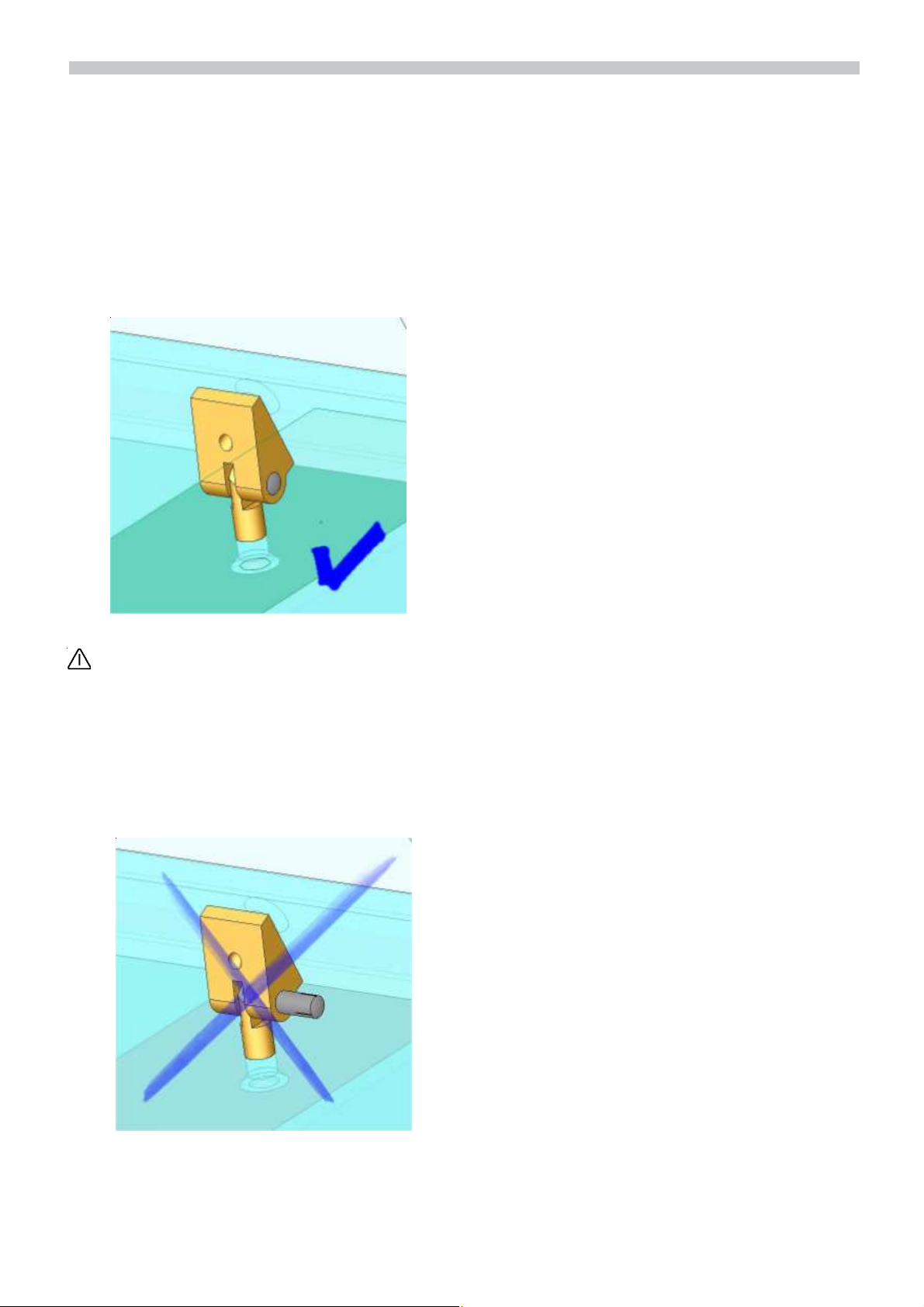
Die Glasscheibe muss zunächst auf die
beiden Befestigungspunkte aufgesetzt werden. Dann muss der Bolzen von außen nach
innen eingedrückt bzw. vorsichtig eingeschlagen werden. Damit der Bolzen eingeschoben werden kann, muss die Scheibe
vorher genau positioniert werden, so daß
der Bolzen durch die Befestigungspunkte
an der Haube durchgesteckt werden kann.
de
Bei der Montage des Bolzens ist unbedingt darauf zu achten, daß dieser vollständig eingeschoben wird. Wird dieser nicht komplett eingeschoben, kann
es zu Beschädigungen der Scheibe
durch Herabfallen kommen. Das herabfallende Glas kann zusätzliche Schäden oder auch Verletzungen nach sich
ziehen.
l
g
h
Montageanleitung
Die Dunstabzugshaube ist für die Montage
an die Küchenwand vorgesehen.
1. Glasblende öffnen Fettfilter abnehmen
(siehe Gebrauchsanleitung).
2. Von der Decke bis zur Unterkante der
Dunstabzugshaube eine Mittellinie an
die Wand anzeichnen.
de
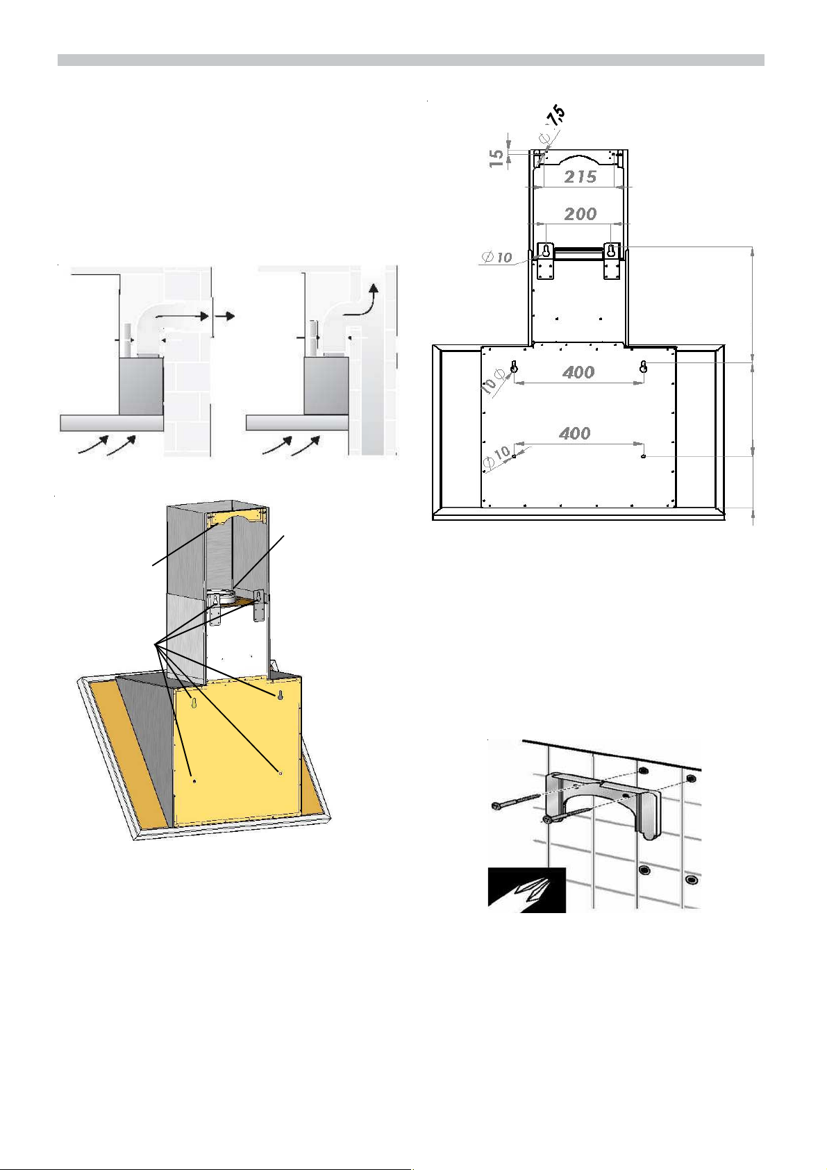
400
Anschluss für
Abluftschlauc
Turmhaltewinke
Befestigungsbohrun
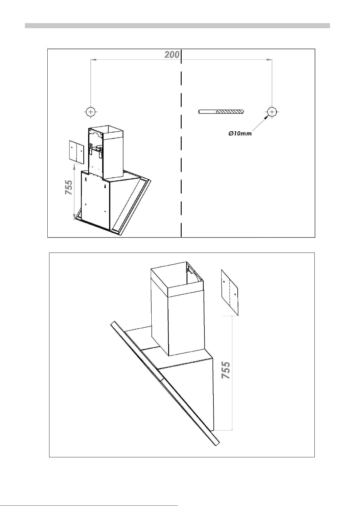
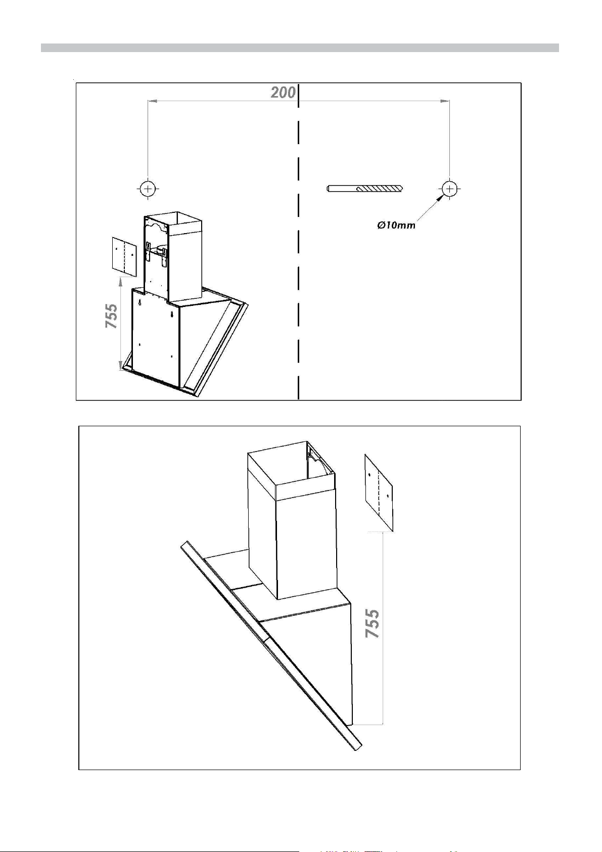
Auf Mindestabstand Kochstelle – Dunstabzugshaube von 400 mm bei Elektro-Kochstellen bzw. 550 mm bei Gas-Kochstellen
achten. Bei Verwendung der Bohrschablone
ist darauf zu achten das der Abstand von
Unterkante Haubenkörper zum unteren
Rand der Bohrschablone 755mm beträgt
(siehe Abb. Bohrschablone).
2 Löcher (Ø6mm) für Turmhaltewinkel.
6 Löcher (Ø10mm) für die Befestigung der
Dunstabzugshaube.
200 300
Bitte auf eine mittige Anordnung der Dunstabzugshaube zu den Kochstellen achten.
3. Löcher bohren und entsprechenden Dübel bündig einsetzen.
4. Aufhängung (Turmhaltewinkel) des
Oberturms befestigen
5. Stockschrauben soweit in die Dübel
( Ø10 mm) einschrauben, dass noch ca.
20 mm hervorstehen.
6. Dunstabzugshaube an den oberen
Befestigungspunkten aufhängen und
mit Unterlegscheiben und Muttern locker
befestigen.
7. Dunstabzugshaube ausrichten
(Montagemaße prüfen) Muttern anziehen.
Bohrschablone
de
Montageanleitung
de
8. Dunstabzugshaube zusätzlich mit
mindestens zwei Schrauben befestigen.
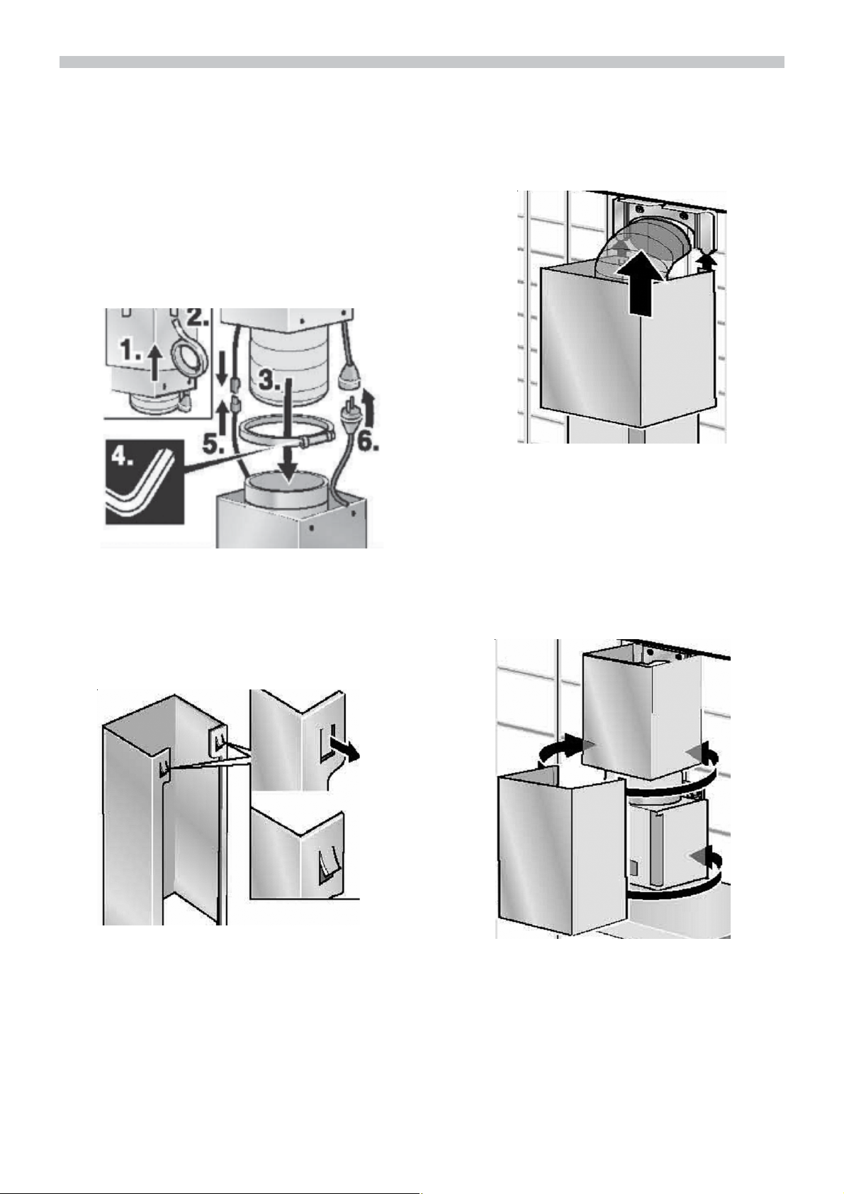
9. (Abluftbetrieb) Abluftschlauch auf richtige Länge ablängen.
10. (Abluftbetrieb) Abluftschlauch anbringen
und befestigen, auf Knickfreiheit achten.
11. Den elektrischen Anschluss herstellen.
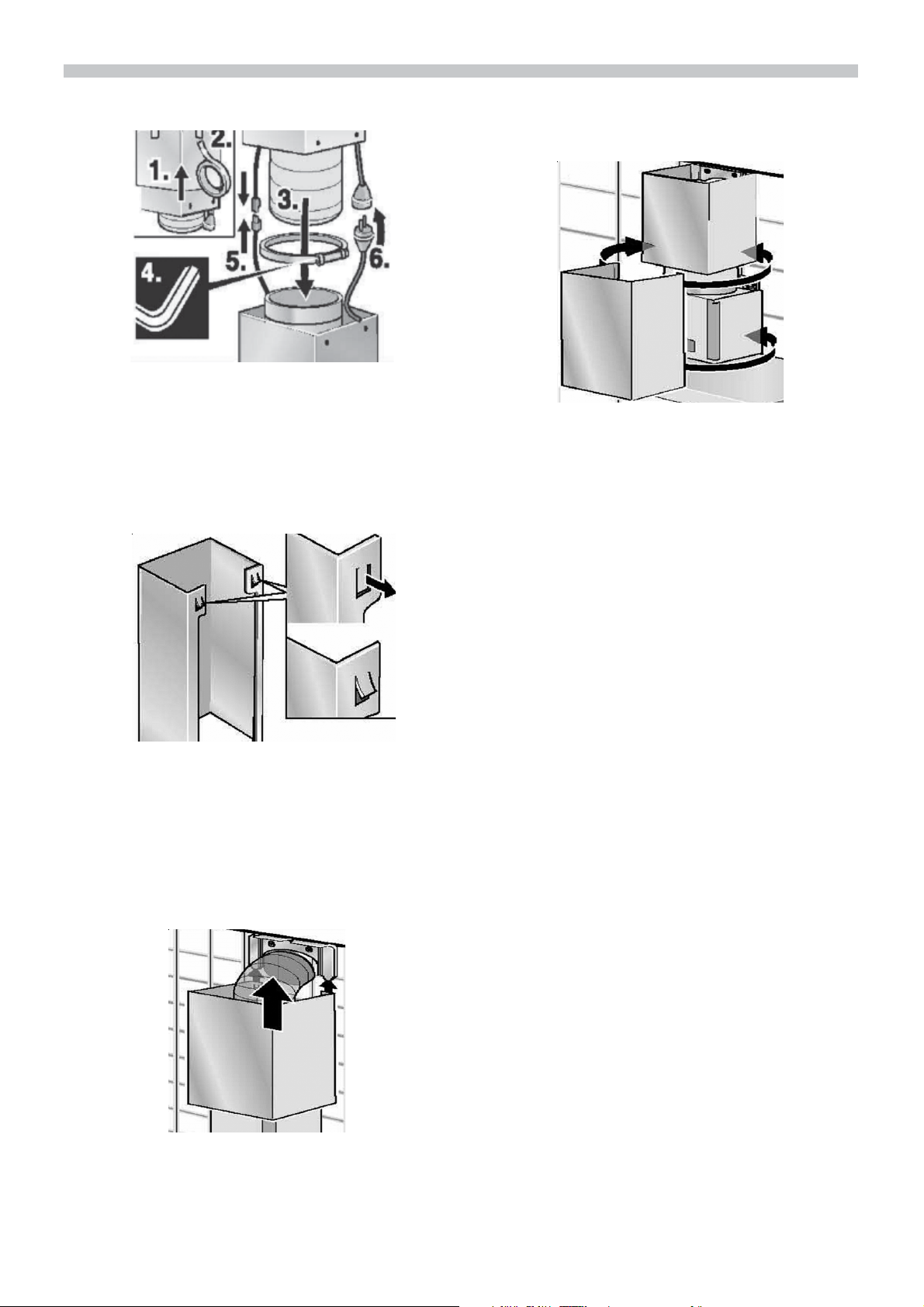
13. Oberturm in die Haltelasche der Turm-
aufhängung einschieben, bis dieser einrastet.
14. Unterturm ein wenig nach außen weiten und über den Oberturm und das Modul der Dunstabzugshaube aufsetzen.
Der Unterturm muss auf der Haube ruhen.
12. Halteauskerbungen am Oberturm 23mm nach außen biegen.

g
Operating Instructions
Chimney
panelling
Light / fan
switches
Lightin
en
When the extractor hood is operated in
exhaust-air mode simultaneously with
a different burner which also makes
use of the same chimney (such as gas,
oil or coal-fired heaters, continuous-flow
heaters, hot-water boilers) care must be
taken to ensure that there is an ade-
quate supply of fresh air which will be
needed by the burner for combustion.
Safe operation is possible provided that
the underpressure in the room where the
burner is installed does not exceed 4 Pa
(0.04 mbar).
This can be achieved if combustion air
can flow through non-lockable openings,
e.g. in doors, windows and via the air intake/exhaust-air wall box or by other
technical measures, such as reciprocal
interlocking, etc.
Chimney
panelling
Filter
Exhaust-air mode:
- The extractor-hood fan extracts the
kitchen vapours and conveys them
through the grease filter into the
atmosphere.
If the air intake is inadequate, there is
a risk of poisoning from combustion
gases which are drawn back into the
room.
An air-intake/exhaust-air wall box by
itself is no guarantee that the limiting
value will not be exceeded.
Note: When assessing the overall
requirement, the combined ventilation
system for the entire household must be
taken into consideration. This rule does not
apply to the use of cooking appliances, such
as hobs and ovens.
- The grease filter absorbs the solid
particles in the kitchen vapours.
- The kitchen is kept almost free of
grease and odours.
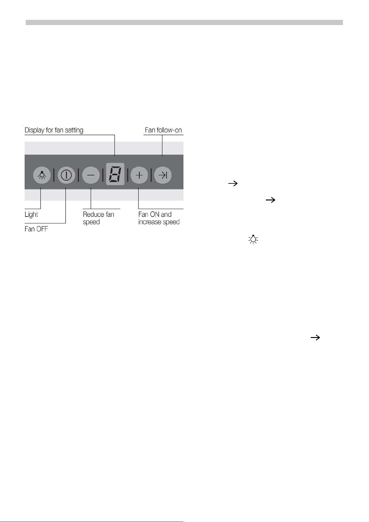
Operating procedure
Important notes:
The Instructions for use apply to several
versions of this appliance. Accordingly, you
may find descriptions of individual features
that do not apply to your specific appliance.
This extractor hood complies with all relevant safety regulations.
Repairs should be carried out by qualified
technicians only.
Improper repairs may put the user at
considerable risk.
Gas hobs / Gas cookers
Do not use all the gas hotplates
simultaneously for a prolonged period
(max. 15 minutes) at maximum thermal
load, otherwise there is a risk of burns if
the housing surfaces are touched or a
risk of damage to the extractor hood. If
the extractor hood is situated over a gas
hob, operate the hood at maximum
setting if three or more gas hotplates are
operated simultaneously.
Before using your appliance for the first;
time, please read these instructions for
use carefully. They contain important
information concerning your personal
safety as well as on use and care of the
appliance.
Please retain the operating and
installation instructions for a subsequent
owner.
Safety instructions
Do not flambé food directly under the
extractor hood.
Risk of grease filter catching fire due ! to
flames.
The hotplates must always be covered with
a utensil.
Restrictions apply to the use of the extractor
hood over a solid-fuel burner (coal, wood,
etc.). (See; Installation instructions).
Do not use the appliance if damaged.
The appliance is not intended for use by
young children or infirmed persons without
supervision. Young children should be
supervised to ensure they do not play with
the appliance.
If the connecting cable for this appliance is
damaged, the cable must be replaced by
the manufacturer or his customer service or
a similarly qualified person in order to
prevent serious injury to the user.
The appliance may be connected to the
mains by a qualified technician only.
Dispose of packaging materials properly
(see; Installation instructions).
This extractor hood is designed for domestic
use only.
Light bulbs must always be fitted when the
extractor hood is in use.
en
This appliance is labelled in accordance
with European Directive 2002/96/EG
concerning used electrical and electronic
appliances (waste electrical and electronic equipment – WEEE). The guideline
determines the framework for the return
and recycling of used appliances as
applicable throughout the EU.
Defective bulbs should be replaced
immediately to prevent the remaining bulbs
from overloading.
Never operate the extractor hood without a
grease filter.
Overheated fat or oil can easily catch fire.
If you are cooking with fat or oil, e.g. chips,
etc., never leave the cooker unattended.
Carefully clean the extractor hood before
switching on for the first time.
Operating procedure
en
Do not place any objects on the extractor
hood.
The most effective method of removing
vapours produced during cooking is to:
Switch the ventilator ON
as soon as you begin cooking.
Switch the ventilator OFF
a few minutes after you have finished
cooking.
Acoustic signal:
When a button is pressed, this is verified by
an acoustic signal.
Switching off the acoustic signal:
Simultaneously press buttons 0 and + until
a signal is emitted after approx. 3 seconds.
Keep pressing the – button until the fan
switches off.
The displayed 0 goes out shortly afterwards.
Intensive setting:
Maximum power is obtained at the intensive setting. It is only required for short
intervals.
Keep pressing the + button until a P appears
in the display.
If the intensive setting is not cancelled by
hand, the fan will automatically switch back
to step 2 after 10 minutes.
Fan follow-on:
Press the
The fan runs for 10 minutes at setting 1.
At the same time the
Then the fan switches off automatically.
Lighting:
Briefly press the button to switch the light
on and off.
The light can be switched on at any time,
even though the fan is switched off.
Switching on the light automatically, e.g.
via a timer:
Fan and light must be switched off.
Switching on:
button.
I
display comes on.
I
Switching on the acoustic signal:
Repeat the process.
Switching the fan ON
Press the + button
Setting the required fan speed:
Press the + button. The fan speed is
increased by one step.
Press the – button.
The fan speed is reduced by one step.
Switching the fan OFF:
Press the 0 button.The displayed 0 goes
out shortly afterwards.
Or:
Simultaneously press the – and
buttons.
After approx. 3 seconds the light switches
on to acknowledge the setting.
Switching off:
Repeat the process with the light switched
on.
After approx. 3 seconds the light
switches off to acknowledge the setting.
I
Filters and maintenance
en
Grease filters:
Metal filters are used to trap the greasy
element of the vapours that develop during
cooking.
The filter mats are made from noncombustible metal.
Caution:
As the filter becomes more and more
saturated with grease, not only does the risk
of it catching fire increase but the efficiency
of the extractor hood can also be adversely
affected.
Important:
By cleaning the metal grease filters at
appropriate intervals, the possibility of them
catching fire as a result of a build-up of heat
such as occurs when deep-fat frying or
roasting is taking place, is reduced.
Saturation indicator:
≡≡≡≡
Removing and inserting the metal grease
filters:
Only change the grease filter when the front
panel is open.
Please only pivot the pane to a maximum
of 90° as the glass pane could otherwise
be destroyed.
1. Press the catches on the front grease
filters and fold down the grease filters
When the grease filters reach saturation
point, an acoustic signal is sounded for 6
seconds after the fan has switched off, and
an
filters should be cleaned straight away.
Cleaning the metal grease filters:
In normal operation (1 to 2 hours daily), the
metal grease filter must be cleaned one a
month.
The filters can be cleaned in a dish-washer.
It is however possible that they will become
slightly discoloured.
The filter must be placed loosely, and NOT
wedged, in the dishwasher.
Important:
Metal filters that are saturated with grease
should not be washed together with other
dishes etc.
When cleaning the filters by hand, soak them
in hot soapy water first of all. Do not use
aggressive, acidic or caustic cleaners.
Then brush the filters clean, rinse them
thoroughly and leave the water to drain off.
appears in the display. The grease
≡≡≡≡
max 90°
2. Press the catches on the rear grease
filters and fold down the grease filters.
3. Clean the grease filter.
2
4. Insert the clean filters back into the hood.
5. Cancel the
Press the button 0.
in the display.
≡≡≡≡
2
en
Cleaning and care
Isolate the extractor hood by pulling out
the mains plug or switching off the fuse.
Do not clean the extractor hood with abrasive
sponges or with cleaning agents which
contain sand, soda, acid or chlorine!
Clean the extractor hood with a hot soap
solution or a mild window cleaner.
Do not scrape off dried-on dirt but wipe off
with a damp cloth.
When cleaning the grease filters, remove
grease deposits from accessible parts of
the housing. This prevents the risk of fire
and ensures that the extractor hood
continues operating at maximum efficiency.
Note: Do not use alcohol (spirit) on plastic
surfaces, as dull marks may appear.
Caution: Ensure that the kitchen is adequately ventilated. Avoid naked flames!
Replacing the light bulbs
1. Switch off the extractor hood and pull
out the mains plug or switch off the
electricity supply at the fuse box.
2. First remove the grease filter (see chapter
Grease Filter and Maintenance)
3. Unscrew the grease filter frame by
loosening the lens-head screws using
the enclosed Allen key. Take particular
care when loosening the last screw as
the grease filter frame could fall down
onto the hob.
4. Replace the defective illuminant (Osram
Dulux S 11W) be carefully pulling it out of
the holder. Please only use the hood with
an illuminant inserted.
Clean the operating buttons with a mild
soapy solution and a soft, damp cloth only.
Do not use stainless-steel cleaner to clean
the operating buttons.
Stainless steel surfaces:
Use a mild non-abrasive stainless steel
cleaner.
Clean the surface in the same direction as
it has been ground and polished.
We recommend our stainless steel cleaner
no. 461731. See enclosed service booklet
for order address.
Aluminium and plastic surfaces:
Do not use dry cloths.
Use a mild window cleaning agent.
Do not use aggressive, acidic or caustic
cleaners.
1
3
1
3
3
1
3
1
5. Now insert the filter frame again and
tighten the 4 cheese-head screws using
the Allen key.
6. Restore the power by inserting the mains
plug or switching on the fuse.

en
If you encounter a problem
Note: If the light does not function, check
that the bulbs have been inserted correctly.
If an
See „Filters and maintenance“ Section.
If is not possible to operate the extractor
hood:
Disconnect the extractor hood from the
mains electricity supply by pulling out the
plug or switching it off at the main fuse box.
Wait for approx. 1 minute and then switch it
on again.
If you have any questions or if a fault occurs,
please call Customer Service.
(See list of Customer Service
representatives).
When you call, please quote the following:
or [ appears in the display:
≡≡≡≡
Installation Instructions:
Important information
Old appliances are not worthless rubbish.
Valuable raw materials can be reclaimed by
recycling old appliances. Before disposing
of your old appliance, render it unusable.
You received your new appliance in a
protective shipping carton. All packaging
materials are environmentally friendly and
recyclable. Please contribute to a better
environment by disposing of packaging
materials in an environmentally-friendly
manner.
Please ask your dealer or inquire at your
local authority about current means of
disposal.
The extractor hood can be used in exhaust
air or circulating air mode.
Always mount the extractor hood over the
centre of the hob.
Minimum distance between electric hob and
bottom edge of extractor hood: 400 mm,
AB - Nr.: FD
Enter the relevant numbers into the box
above. The AB - Nr. (product no.) and FD
(production date) are shown on the
nameplate which can be seen inside the
extractor hood after the filter frame has been
detached.
The manufacturer of the extractor hoods
accepts no liability for complaints which can
be attributed to the design and layout of the
pipework.
The extractor hood must not be installed over
a solid fuel cooker - a potential fire hazard
(e.g. flying sparks) -unless the cooker
features a closed, non-removable cover
and all national regulations are observed.
The smaller the gap between the extractor
hood and hotplates, the greater the
likelihood that droplets will form on the
underside of the extractor hood.
Additional information concerning gas
cookers:
When installing gas hotplates, comply with
the relevant national statutory regulations
(e.g. in Germany: Technische Regeln Gasinstallation TRGI).
Always comply with the currently valid
regulations and installation instructions
supplied by the gas appliance manufacturer.
Only one side of the extractor hood may be
installed next to a high-sided unit or high
wall. Gap at least 50 mm.
Minimum distance on gas hotplates
between the upper edge of the trivet
and lower edge of the extractor
hood: 550 mm
Installation Instructions
en
The exhaust air is discharged upwards
through a ventilation shaft or directly through
the outside wall into the open.
Exhaust air should neither be directed into
a smoke or exhaust flue that is currently
used for other purposes, nor into a shaft
that is used for ventilating rooms in which
stoves or fireplaces are also located.
Exhaust air may be discharged in
accordance with official and statutory
regulations only (e.g. national building
regulations).
Local authority regulations must be
observed when discharging air into smoke
or exhaust flues that are not otherwise in
use.
When the extractor hood is operated in
exhaust-air mode simultaneously with a
different burner which also makes use of
the same chimney (such as gas, oil or coal-
fired heaters, continuous-flow heaters, hotwater boilers) care must be taken to
ensure that there is an adequate supply
of fresh air which will be needed by the
burner for combustion.
Safe operation is possible provided that the
underpressure in the room where the burner
is installed does not exceed 4 Pa (0.04
mbar).
This can be achieved if combustion air can
flow through non-lockable openings, e.g. in
doors, windows and via the air-intake/
exhaust-air wall box or by other technical
measures, such as reciprocal interlocking,
etc.
If the air intake is inadequate, there is a
risk of poisoning from combustion gases
which are drawn back into the room.
An air-intake/exhaust-air wall box by itself is
no guarantee that the limiting value will not
be exceeded.
Note: When assessing the overall
requirement, the combined ventilation
system for the entire household must be
taken into consideration. This rule does not
apply to the use of cooking appliances, such
as hobs and ovens.

Prior to installation
en
For optimum extractor hood efficiency:
Short, smooth air exhaust pipe.
As few bends in the pipe as possible.
Diameter of pipe to be as large as possible
and no tight bends in pipe.
If long, rough exhaust-air pipes, many pipe
bends or smaller pipe diameters are used,
the air extraction rate will no longer be at
an optimum level and there will be an
increase in noise.
The manufacturer of the extractor hoods
accepts no liability for complaints which
can be attributed to the design and layout
of the pipework.
Round pipes:
Internal diameter: 150 mm or bigger.
We recommend internal diameters of
150mm or larger.
Flat ducts must have an internal cross-
section that equates to that of round pipes.
For exhaust-air mode, ensure that there
is an adequate supply of fresh air.
WARNING: THIS APPLIANCE MUST BE
Electrical connection
EARTHED
2. Connect the blue (Neutral) wire to the ter
minal in the plug marked ‘N’ or coloured
black.
3. Connect the brown (Live) wire to the ter
minal marked ‘L, or coloured red.
The extractor hood should only be
connected to an earthed socket that has
been installed according to relevant
regulations. If possible, site the earthed
socket directly behind the chimney panelling.
Electrical data:
Are to be found on the name plate inside the
appliance after removal of the filter frame.
Before undertaking any repairs,
always disconnect the extractor hood from
the electricity supply.
Length of the connecting cable: 1.30 m.
If it is necessary to wire the extractor hood
directly into the mains:
The extractor hood should only be connected
to the electricity supply by a properly qualified
electrician.
A separator must be installed in the household circuit. A suitable separator is a switch
that has a contact gap of more than 3 mm
and interrupts all poles. Such devices
include circuit breakers and contactors.
If the connecting cable for this appliance is
damaged, the cable must be replaced by
the manufacturer or his customer service or
a similarly qualified person in order to
prevent serious injury to the user.
IMPORTANT: Fitting a Different Plug:
The wires in the mains lead are coloured in
accordance with the following code:
Green and Yellow - Earth
Blue - Neutral
Brown - Live
If you fit your own plug, the colours of these
wires may not correspond with the
identifying marks on the plug terminals.
This is what you have to do:
1. Connect the green and yellow (Earth) wire
to the terminal in the plug marked ‘E’ or
with the symbol, or coloured green or green
and yellow.
This extractor hood corresponds to EC
regulations concerning RF interference
suppression.
In order to avoid damage during
transportation, the front glass panel will be
packaged separately from the hood body
and must be connected to the hood border
after unpacking (see following illustration).
Prior to installation
en
The glass pane must then be placed on
both attachment points. Then the bolts
must be pressed in from the outside and/
or carefully tapped in. For the bolts to be
able to pushed in, the pane must first be
positioned precisely so that the bolts can
be pressed through the attachments
points on the hood.
2
1
1
When installing the bolts, make
absolutely sure that they have been
pushed in completely. If these are not
pushed in completely, the pane could
be damaged by falling out. The falling
glass could caused additional damage
or injuries.
2
1
2
Installation
r
e
This extractor hood is intended to be
mounted onto the kitchen wall.
Open glass aperture.
1. Remove the grease filter (refer to
operating; Instructions).
2. Draw a line on the wall from the ceiling to
the lower edge of the hood at the centre of
the location where the hood is going to be
mounted.
en
400
200 300
Connection
Tower
Holde
Wall Fastener
Ensure that the minimum distance between
the hob and the extractor hood is maintained
- 400 mm for an electric hob and 550 mm
for a gas hob. 1.) When using the drilling
template, please ensure that the clearance
between the bottom edge of the hood
body and the bottom edge of the drilling
template is 755 mm (see Fig. drilling
template).
for Hos
4. Hole (diameter 10mm) for the attachment
of the exhaust hood.
5. Please be certain to center the exhaust
hood over the cooking area.
6. Drill the holes and insert suitable screw
anchors flush.
7. Attach suspension (tower holder angle)
to the upper tower.
8. Screw machine screws into the screw
anchors (Ø10 mm) until they protrude by
about 20mm.
9. Hang the exhaust hood on the upper
attachment points and loosely fasten it
using the washers and nuts.
10. Align the exhaust hood (inspect the
installation) and tighten the nuts.
3. Drill 2x 6 mm ø holes for the upper fixing
bracket.
11. Additionally secure the exhaust hood with
two additional screws.
en
Installation /
Drilling template
Installation
12. (Exhaust operation) Cut the exhaust
hose to the proper length.
13. (Exhaust hose) Attach and tighten the
exhaust hose, be sure that it is free of
bends.
14. Bend the retaining grooves on the upper
tower outwards approximately 2-3 mm.
en
17. Connect the hood to the electricity supply.
15. Slide the upper tower into the retaining
tongue on the tower mount until it clicks
into place.
16. Pull the under tower slightly outwards
and place the upper tower and the
exhaust hood module on it. The
undertower must be touching the hood.

Mode d’emploi Description de l’appareil
chauffage (tels par ex. des appareils de
Capot de
Cheminèe
Commutateur
Lumière/
Ventilateur
Eclairage
Capot de
Cheminèe
chauffage au gaz, au fuel ou au charbon,
chauffe-eau instantanés ou à accumulation)
raccordés à une cheminée, veiller
impérativement à ce que l’apport d’air soit
suffisant pour assurer la marche du
chauffage à combustion.
Un fonctionnement sans risque est
possible si la dépression dans le local où
le foyer de chauffage est implanté ne
dépasse pas 4 Pascals (0,04 mbars).
Modes de fonctionnement
On y parvient en présence d’ouvertures non
obturables ménagées par ex. dans les
portes, fenêtres et en association avec des
ventouses télescopiques d’admission/
évacuation de l’air à travers la maçonnerie
ou par d’autres mesures techniques telles
qu’un verrouillage réciproque ou assimilé
permettant à l’air d’affluer pour assurer la
combustion.
fr
Grille du
filtre
Modes de fonctionnement
Air évacué à l’extérieur:
Le ventilateur de la hotte aspire les buées
de cuisson qui traversent un filtre à graisse
avant de regagner l’atmosphère extérieure.
Ce filtre retient les particules grasses solides en suspension dans les buées de
cuisson.
En cas d’afflux d’air insuffisant, risque
d’intoxication par réaspiration des gaz
de combustion.
La présence d’une ventouse télescopique
d’apport et d’évacuation d’air ne suffit pas à
assurer le respect de la valeur limite.
Remarque: lors de l’évaluation de la
situation, toujours tenir compte de
l’ensemble des moyens d’aération du
logement. Cette règle ne vaut généralement
pas si vous utilisez des appareils de cuisson
(table de cuisson et cuisinière à gaz).
Les particules grasses ne se déposent plus
dans la cuisine, les odeurs de cuis-son
disparaissent.
Si la hotte évacue l’air à l’extérieur et si le
logement comporte des moyens de

Avant la première utilisation
fr
Remarques importantes:
La présente notice d’emploi vaut pour
plusieurs versions de l’appareil. Elle peut
contenir des descriptions d’accessoires ne
figurant pas dans votre appareil.
Cette hotte aspirante est conforme aux
dispositions de sécurité applicables.
Les réparations ne doivent être effectuées
que par un spécialiste.
Des réparations inexpertes s’assortissent
de risques considérables pour l’utilisateur.
Tables de cuisson au gaz / Cuisinières à
gaz
Ne faites jamais marcher tous les foyers au
gaz en même temps et à pleine puissance
pendant assez longtemps (15 minutes
max.), sinon vous risquez de vous brûler en
touchant la surface du corps de la hotte, ou
d’endommager carrément cette dernière. Si
la hotte doit marcher au-dessus d’une table
de cuisson au gaz, faites simultanément
marcher la hotte à la puissance d’aspiration
maximale si vous avez allumé trois foyers
ou plus.
Consignes de sécurité
Ne flambez aucun mets sous la hotte. I Les
flammes risq ueraient d’atteindre le filtre à
graisse et d’y mettre le feu.
Lorsque les foyers sont allumés, des
ustensiles de cuisson doivent toujours se
trouver dessus.
L’utilisation d’une hotte aspirante audessus d’un foyer à combustible solide
(charbon, bois, etc.) n’est autorisée qu’à
certaines conditions (voir la notice de
montage).
Si l’appareil est endommagé, sa mise en
service est proscrite.
Le branchement et la mise en service ne
doivent être effectués que par un spécialiste.
Si le cordon d’alimentation de cet appareil
a été endommagé, il faut confier son
remplacement au fabricant ou à son service
après-vente, ou encore à une personne
possédant des qualifications identiques,
pour éviter de créer des risques.
Lisez attentivement la présente notice
d’emploi avant d’utiliser votre appareil pour
la première fois. Elle contient des
informations importantes non seulement
pour votre sécurité mais aussi pour
l’utilisation et l’entretien de l’appareil.
Rangez la présente notice de montage et
d’emploi soigneusement pour pouvoir la
remettre à un futur propriétaire de l’appareil.
Cet appareil est marqué selon la directive
euro-péenne 2002/96/CE relative aux
appareils élec-triques et électroniques
usagés (waste electrical and electronic
equipment– WEEE). La directive définit le
cadre pour une reprise et une récupération
des appareils usagés applicables dans les
pays de la CE.
Eliminez les matériaux d’emballage
conformément à la réglementation (voir la
notice de montage).
Cette hotte aspirante n’est destinée à servir
que pour couvrir les besoins d’un ménage.
Ne faites marcher la hotte aspirante
qu’ampoules montées sur leur douille.
Remplacez immédiatement les ampoules
défectueuses pour empêcher une
surcharge des ampoules restantes.
N’utilisez jamais la hotte aspirante sans filtre
à graisse.
Les graisses ou huiles surchauffées
peuvent s’enflammer facilement. Par
conséquent, surveillez toujours les plats
(frites par ex.) qui se préparent à l’aide de
matières grasses ou d’huiles.
Avant la première mise en service, nettoyez
soigneusement la hotte aspirante.
Ne posez rien sur la hotte aspirante.

Utilisation de la hotte aspirante
La méthode la plus efficace pour supprimer
les buées de cuisson consiste à:
Enclencher la hotte aspirante
en début de cuisson.
Eteindre la hotte aspirante
quelques seulement minutes après la fin
de la cuisson.
Ventilation intensive:
Au niveau intensif, le ventilateur développe
sa plus grande puissance. Vous n’en aurez
que brièvement besoin.
Appuyez sur la touche + autant de fois que
nécessaire à ce que la lettre P s’affiche.
Si vous n’éteignez pas manuellement la
ventilation intensive, le ventilateur revient
automatiquement à la vitesse 2 au bout de
10 minutes.
Poursuite de marche du ventilateur:
Appuyez sur la touche
Le ventilateur marche pendant
10 minutes à la puissance 1. Ce faisant,
le témoin lumineux
Le ventilateur s’éteint ensuite
automatiquement.
Eclairage:
Pour allumer et éteindre l’éclairage, appuyez
brièvement sur la touche
s’allume.
I
fr
Signal sonore:
Lorsque vous appuyez sur une touche, un
signal sonore retentit à titre de confirmation.
Coupure du signal sonore:
Appuyez simultanément sur les touches 0
et + jusqu’à ce que, env. 3 secondes plus
tard, un signal retentisse.
Enclenchement du signal sonore:
Répétez cette opération.
Enclenchement du ventilateur:
Appuyez sur la touche
Réglage du ventilateur sur la vitesse
désirée:
Appuyez sur la touche +.
Le ventilateur passe au gradin de vitesse
immédiatement supérieur.
Appuyez sur la touche –.
Le ventilateur passe au gradin de vitesse
immédiatement inférieur.
Coupure du ventilateur:
Appuyez sur la touche 0.
La mention 0 s’éteint au bout d’un temps
bref.
Vous pouvez utiliser l’éclairage à tout
moment, même quand le ventilateur est
éteint.
Enclenchement automatique de
l’éclairage, par ex. au moyen d’un
minuteur:
Le ventilateur et l’éclairage doivent être
éteints.
Enclenchement:
Appuyez simultanément sur les touches –
et
I
Au bout de 3 secondes env., l’éclairage
s’enclenche pour confirmation.
Coupure:
Répétez le processus d’enclenchement de
l’éclairage.
Au bout de 3 secondes env., l’éclairage
s’éteint pour confirmation.
Ou:
Appuyez sur la touche – autant de fois que
nécessaire à ce que le ventilateur s’éteigne.
La mention 0 s’éteint au bout d’un temps
bref.

Filtre et entretien
fr
Filtres à graisse:
Vous pouvez utiliser divers filtres pour
retenir les particules grasses en
suspension dans les buées de cuisson.
Ces nattes filtrantes sont en métal
incombustible.
Attention:
Plus elles se saturent en particules grasses
et plus elles risquent de s’enflammer.
D’autre part, leur saturation risque de gêner
le bon fonctionnement de la hotte.
Important:
Prévenez tout risque d’incendie en net-toyant
à temps les filtres à graisse en métal. Ce
risque est dû à l’accumulation de chaleur
pendant la friture ou le rôtissage.
Indicateur de saturation:
Lorsque les filtres à graisse sont saturés,
un signal retentit pendant 6 secondes après
la coupure du ventilateur et la lettre z est
allumée. Vous devrez nettoyer les filtres à
graisse au plus tard à ce stade de saturation.
≡≡≡≡
Retrait et mise en place des filtres à
graisse en métal:
Changer le filtre à graisse uniquement avec
la vitre frontale ouverte
1. Ne changez les filtres à huile qu’avec le
capot ouvert.
Pivoter la vitre au maximum de 90° car,
dans le cas contraire, la vitre en verre
risque d’être détruite.
max 90°
Nettoyage des filtres à graisse en métal:
En service normal (1 à 2 heures par jour), il
faudra nettoyer les filtres à graisse
métalliques 1 fois par mois.
Ces filtres sont nettoyables au lavevaisselle. Ils peuvent changer légèrement
de couleur au lavage.
Le filtre doit reposer non serré dans le lavevaisselle. Il ne doit pas être coincé.
Important:
Ne lavez pas en même temps la vaisselle
et les filtres métalliques fortement saturés
en matière grasse.
Si vous les nettoyez à la main, mettez les
filtres à tremper pendant plusieurs heures
dans de l’eau très chaude additionnée de
produit à vaisselle.
N’utilisez pas de détergents aggressifs,
contenant un acide ou une base. Ensuite,
brossez les filtres, rincez-les bien puis
laissez-les goutter.
2. Appuyez sur les crans du filtre à graisse
avant puis basculez ce dernier vers le
bas.
2
3. Appuyez sur les crans du filtre à graisse
arrière puis basculez ce dernier vers le bas.
4. Nettoyez le filtre à graisse.
5. Une fois nettoyés, remettez les filtres à
graisse en place.

Nettoyage et entretien Changer les ampoules halogènes
2
6. Faites s’effacer la lettre
Appuyez sur la touche 0.
Avant tout nettoyage et entretien, mettez
d’abord la hotte hors tension en débranchant la fiche mâle de la prise de courant
ou en coupant le disjoncteur/fusible
Nettoyez les surfaces en aluminium
uniquement avec un peu de lessive et un
chiffon tres doux. Nettoyez le panneau de
commande avec un chiffon doux humide.
Pour les modèles équipés d’une plaque
sous le filtre (aspiration par les côtés), la
graisse se dépose au niveau des rebords
de la plaque. Ces dépôts sont des résultats
physiques et non une anomalie dans le
fonctionnement. Veuillez nettoyer
régulierement la plaque sous le filtre pour
éviter que les saletés ne s’incrustent.
Pour la nettoyer, utilisez de l’eau chaude
additionnée de produit à vaisselle ou un liquide non agressif à laver les fenêtres.
Ne tentez pas de gratter les salissures.
Ramollissez-les avec un essuie-tout humide.
Lors du nettoyage des filtres à graisse,
nettoyez la graisse qui s’est déposée dans
les endroits accessibles du corps de hotte.
Vous prévenez ainsi les risques d’incendie
et garantissez ainsi un fonctionnement optimal de la hotte.
Remarque: ne nettoyez pas les surfaces en
plastique avec de l’alcool (à brûler) car des
taches mates pourraient apparaître.
Prudence: ventilez suffisamment la cuisine,
n’utilisez jamais de flamme nue.
Ne nettoyez les touches de commande
qu’avec de l’eau additionnée d’un peu de
produit à vaisselle. Utilisez un chiffon doux
et humide.
N’utilisez jamais de détergent pour acier pour
nettoyer les touches de commande.
Surfaces en acier inox:
Veuillez utiliser un produit pour l’acier inox
qui le nettoie sans le rayer.
≡≡≡≡
.
Utilisez un produit pour vitres mais non
aggressif. N’utilisez pas de détergents
aggressifs, contenant un acide ou une base.
Changer le halogènes uniquement avec la
vitre frontale ouverte
1. Avant tout nettoyage et entretien, mettez
d’abord la hotte hors tension en
débranchant la fiche mâle de la prise de
courant ou en coupant le isjoncteur/
fusible.
1
3
1
3
3
1
3
1
2. Dégager le filtre à graisse (voir chapitre
filtre à graisse et entretien)
3. Dévissez le cadre du filtre à graisse au
moyen de la clé Allen fournie ; pour ce
faire, desserrez les vis à tête bombée.
Attention à la dernière vis pour que le
cadre du filtre à graisse ne tombe pas
sur le plan de cuisson.
4. Changer l’ampoule défectueuse ((Osram
Dulux S 11W) en la tirant avec soin de
son logement. Veuillez utiliser la hotte
uniquement avec une ampoule enfichée.
fr
Frottez toujours l’acier inox dans le sens de
son polissage.
Surfaces en aluminium et en plastique:
N’utilisez pas de chiffons secs.
5. Réintroduisez maintenant le cadre du
filtre et revissez les 4 vis à tête bombée
au moyen de la clé Allen fournie.

Dérangements Notice de montage:
fr
Si
Voir la section intitulée „Filtre et entretien“.
Si les touches de la hotte aspirante restent
inopérantes:
Débranchez pendant une minute environ la
fiche mâle de la hotte aspirante ou retirez le
fusible pour la mettre hors tension. Ensuite,
réenclenchez la hotte.
Si vous avez des questions à poser ou en
cas de dérangement, appelez s.v.p. le
service après-vente.
(Voir la liste des agences du service aprèsvente).
Lors de votre appel, veuillez mentionner les
numéros suivants:
ou [ apparaît à l’indicateur:
≡≡≡≡
AB Nr.: FD
Inscrivez les numéros correspondants de
votre hotte dans le cadre ci-dessus. Ces
numéros se trouvent à l’intérieur de
l’appareil, sur la plaque signalétique
accessible une fois la grille de filtre retirée.
Si des réclamations résultent de la
conception et de la pose de la conduite, le
fabricant de la hotte aspirante décline
toute garantie.
Remarques importantes
Les anciens appareils ne sont pas des
déchets sans valeur. Leur élimination
respectueuse de l’environnement permet
de récupérer de précieuses matières
premières. Avant de vous débarrasser de
l’appareil, rendez-le inutilisable.
Pour vous parvenir en parfait état, votre
nouvel appareil a été conditionné dans un
emballage qui le protège efficacement.
Tous les matériaux d’emballage utilisés sont
compatibles avec l’environnement et
recyclables. Aidez-nous à éliminer
l’emballage en respectant l’environnement.
Demandez à votre revendeur ou à votre
mairie quelles sont les formes de recyclage
actuellement possibles.
Fixez toujours la hotte bien centrée audessus des foyers de la table de cuisson.
L’écart minimum entre les foyers électriques
et le bord inférieur de la hotte doit être de
400 mm, voir fig. 1.
Au-dessus d’un foyer à combustible solide
générateur d’un risque d’incendie (par
projection d’étincelles par ex.), le montage
de la hotte ne sera admis que si ce foyer est
équipé d’un couvercle fermé et inamovible
et si le montage ne contrevient pas à la
réglementation nationale. Cette restriction
ne vaut pas pour les cuisinières à gaz et les
foyers aux gaz.
Plus l’écart est faible entre la hotte aspirante
et les foyers et plus il se pourra que la vapeur
montant des casseroles se condense et
forme des gouttes sur la face inférieure de
la hotte.
Remarques supplémentaires concernant
les cuisinières à gaz:
Lors du montage de foyers gaz, veuillez
respecter les dispositions légales en
vigueur dans votre pays (En Allemagne par
ex: les Règles technique TRGI régissant
l’installation du gaz).
Respectez les prescriptions et consignes
d’encastrement en leur version applicable
publiées par les fabricants d’appareils au
gaz.
La hotte aspirante ne pourra cotoyer que
sur un côté un meuble haut ou une paroi
haute. Ecart minimum: 50 mm.

Avant le montage
fr
Ecart minimum, en présence de
foyers au gaz, entre le bord supérieur
de la grille support et le bord inférieur de la
hotte: 550 mm, fig. 1.
L’air vicié est évacué vers le haut par un
conduit d’aération ou directement à l’air libre
par traversée du mur extérieur.
D L’air vicié ne doit jamais être évacué vers
une cheminée en service, rejetant des
fumées ou des gaz de combustion, ni vers
un conduit servant à l’aération de locaux
dans lesquels se trouvent des foyers à
combustibles solides, liquides et gazeux.
Le mode d’évacuation de l’air vicié devra
être conforme aux arrêtés municipaux,
préfectoraux, et aux prescriptions légales
(par ex. aux ordonnances publiques
applicables au bâtiment).
Si l’air vicié doit être évacué par des
cheminées d’évacuation des fumées et gaz
de combustion qui ne sont pas en service,
veuillez respecter la réglementation locale
et nationale applicable.
Si la hotte évacue l’air à l’extérieur et si le
logement comporte des moyens de
chauffage (tels par ex. des appareils de
chauffage au gaz, au fuel ou au charbon,
chauffe-eau instantanés ou à accumulation) raccordés à une cheminée, veiller
impérativement à ce que l’apport d’air soit
suffisant pour assurer la marche du
chauffage à combustion. Un
fonctionnement sans risque est possi-ble
si la dépression dans le local où le foyer de
chauffage est implanté ne dépasse pas 4
Pascals (0,04 mbars). On y parvient en
présence d’ouvertures non obturables
ménagées par ex. dans les portes, fenêtres
et en association avec des ventouses
télescopiques d’admission/ évacuation de
l’air à travers la maçonnerie ou par d’autres
mesures techniques telles qu’un
verrouillage réciproque ou assimilé
permettant à l’air d’affluer pour assurer la
combustion.
En cas d’afflux d’air insuffisant, risque
d’intoxication par réaspiration des gaz de
combustion.
La présence d’une ventouse télescopique
d’apport et d’évacuation d’air ne suffit pas à
assurer le respect de la valeur limite.
Remarque: lors de l’évaluation de la
situation, toujours tenir compte de
l’ensemble des moyens d’aération du
logement. Cette règle ne vaut généralement pas si vous utilisez des appareils de
cuisson (table de cuisson et cuisinière à
gaz).

fr
2
2
Avant le montage
Pour que la hotte aspirante ait le meilleur
rendement, veillez à ce que:
Le conduit d’évacuation soit court et lisse.
Il ait le moins possible de coudes.
Il ait le plus fort diamètre et que les coudes
soient les plus arrondis possibles.
L’emploi de conduits d’air vicié longs,
rugueux, formant de nombreux coudes ou
d’un trop petit diamètre fait descendre le
débit d’air en dessous du débit optimal,
tout en accroissant le bruit d’aspiration.
Si des réclamations résultent de la
conception et de la pose de la conduite, le
fabricant de la hotte aspirante décline
toute garantie.
Conduits de section ronde:
Nous recommandons un diamètre intérieur
de 150 mm ou plus grand.
Les conduits plats doivent avoir une section
intérieure équivalente au
diamètre intérieur des conduits ronds.
Si la hotte évacue l’air à l’extérieur,
veillez à ce que l’apport d’air soit suffisant.
Branchement électrique
l’ouverture entre contacts dépasse 3 mm et
qui sectionnent tous les pôles. Figurent
parmi eux également les disjoncteurs et
contacteurs.
Si le cordon d’alimentation de cet appareil
a été endommagé, il faut confier son
remplacement au fabricant ou à son service
après-vente, ou encore à une personne
possédant des qualifications identiques,
pour éviter de créer des risques.
Cette hotte aspirante est conforme aux
dispositions CE sur l’antiparasitage des
appareils électriques.
Afin de préserver les détériorations dues
au transport, la vitre frontale est emballée
séparément du corps de la hotte et doit être
reliée à celui-ci après le déballage (voir
dessin ci-après)
La vitre en verre doit tout d’abord être
posée sur les deux points de fixation. Le
boulon doit ensuite être introduit de
l’extérieur vers l’intérieur ou être enfoncé
avec précaution. Afin de pouvoir
Fixez le tuyau d’air vicié contre le manchon
réducteur.
La fiche mâle de la hotte aspirante ne
pourra être branchée que dans une prise
secteur à contacts de terre réglementairement posée. Installer cette prise autant que
possible directement derrière le capotage
de la hotte.
Caractéristiques électriques:
Vous les trouverez après avoir retiré le cadre
pour filtre, sur la plaque signalétique, à
l’intérieur de l’appareil.
Toujours mettre l’appareil hors tension
avant d’effectuer des réparations.
Longueur du cordon de branchement: 1,30
m.
Si le cordon doit être raccordé
définitivement au secteur:
Dans ce cas, le branchement de la hotte ne
pourra être effectué que par un électricieninstallateur agréé auprès de la compagnie
locale/nationale distributrice d’électricité.
Prévoir un dispositif de coupure côté secteur.
Valent comme tel les commutateurs dont
1
1
1
2

Avant le montage
introduire le boulon, la vitre doit
auparavant être positionnée avec
exactitude pour que le boulon puisse traverser les points de fixation sur la hotte.
Lors du montage du boulon, il convient
de veiller à ce qu’il soit complètement
enfoncé. S’il est n’est pas complètement
enfoncé, la vitre risque de tomber et d’être
fr
endommagée. La chute du verre peut
s’accompagner de dommages
supplémentaires ou entraîner aussi des
blessures.
Cette hotte aspirante est prévue pour le
montage contre le mur de la cuisine.
Ouvrir le panneau en verre.

Encastrement
n
1. Retirer le filtre à graisse (voir la notice
d’utilisation).
2. Sur le mur, tracez une ligne médiane
allant du plafond jusqu’au bord inférieur
de la hotte aspirante.
3. Percez 2 trous pour la cornière de
retenue supérieure et 2 trous pour la
cornière de retenue inférieure, de 6 mm
de diamètre chacun, puis enfoncez les
fr
400
Raccord pour
Equerre de
maintien
du corps
Perçage de
fixatio
chevilles jusqu’à ce qu’elles affleurent
avec le mur. Lors de l’utilisation d’un
gabarit de perçage, veiller à ce que
l’écart entre le rebord inférieur du corps
de la hotte et le bord inférieur du
gabarit soit de 755 mm (voir ill. Gabarit
de perçage).
4. Trous (diamètre 10 mm) pour la fixation
de la hotte
conduit d’air
d’échappement
200 300
5. Veillez à disposer la hotte de manière
centrée par rapport à la table de cuisson
6. Percer les trous et placer les chevilles
affleurées.
7. Fixer la suspension (angle de fixation du
conduit) du conduit supérieur.
8. Visser les vis dans les chevilles (diamètre
10 mm) car env. 20 mm dépassent.
9. Suspendre la hotte aux points de fixations
supérieurs et fixer sans serrer avec des
rondelles et des écrous.
10. Ajuster la hotte (vérifier les mesures de
montage) et serrer les écrous.

fr
Encastrement /
Gabarit de perçage

Encastrement
fr
11. Fixer la hotte avec au moins deux vis
supplémentaire.;
12. (Fonctionnement de l’évacuation d’air)
Découper le tuyau d’évacuation à la
bonne longueur
13. (Fonctionnement de l’évacuation d’air)
placer et fixer le tuyau d’évacuation et
respecter une liberté de flexion
16. Elargir le conduit inférieur vers l’extérieur
et placer la hotte au-dessus du conduit
supérieur et du module. Le conduit
inférieur inférieure doit se poser sur la
hotte.
14. Plier les languettes de maintien du
conduit supérieur de 2-3 mm vers
l’extérieur.
15. Insérer le conduit supérieur dans la
languette de maintien de la suspension
du conduit jusqu’à ce qu’il s’enclique.

Gebruiksaanwijzing
Schoorsteenafscherming
nl
Gebruik zonder gevaar is mogelijk als de
onderdruk van 4 Pa (0,04 mbar) in de
opstellingsruimte van de stookinstallatie niet
wordt overschreden.
Schakelaars
verlichting en
ventilator
Schoorsteenafscherming
Verlichting
Gebruiksmogelijkheden
Dit kan men bereiken wanneer er door niet-
afsluitbare openingen, bijv. in deuren, ramen
en d.m.v. luchtaanvoer-/ luchtafvoersleuven
in de muur of door andere technische
maatregelen, zoals wederzijdse
vergrendeling e.d., verbrandingslucht kan
toestromen.
Wanneer er onvoldoende lucht wordt
aangevoerd, bestaat er vergiftigingsgevaar door teruggezogen verbrandingsgassen.
Alleen een muurkast voor luchttoevoer en
luchtafvoer is geen waarborg voor het
aanhouden van de grenswaarde.
Opmerking: bij de beoordeling moet altijd
de complete ventilatie van de woning in acht
worden genomen. Bij het gebruik van
kookapparatuur, bijvoorbeeld kookplateau
en gasfornuis, wordt deze regel niet
toegepast.
Filterrooster
Gebruiksmogelijkheden
Gebruik met luchtafvoer:
De ventilator van de afzuigkap zuigt de
keukenwasem aan en leidt deze via het
vetfilter naar buiten.
Het vetfilter neemt de vaste
bestanddelen van de keukenwasem op.
De keuken blijft in grote mate vrij van vet en
reuk.
Als de wasemafzuigkap wordt gebruikt
met luchtafvoer en tegelijkertijd
schoorsteenafhankelijke stookinstallaties worden gebruikt (zoals gas-,
olie- of kolenstookapparaten, geisers,
warmwaterbereidingsapparaten) moet voor
voldoende aanvoer van lucht worden
gezorgd, die nodig is voor de verbranding.

Vóór het eerste gebruik
Belangrijke aanwijzingen:
Deze gebruiksaanwijzing geldt voor verschillende uitvoeringen van het apparaat.
Het is mogelijk dat er een aantal kenmerken
worden beschreven die niet van toepassing
zijn op uw apparaat.
Deze afzuigkap voldoet aan de geldende
veiligheidsvoorschriften.
Reparaties mogen uitsluitend worden
uitgevoerd door een vakman.
Door ondeskundige reparaties kunnen
aanzienlijke gevaren voor de gebruiker
ontstaan.
Gaskookplaten / gasfornuizen
Gebruik niet alle gaskookzones tegelijk
langdurig (max. 15 minuten) op de hoogste
stand, anders bestaat er kans op
brandwonden bij aanraking van de
oppervlakken van de behuizing en gevaar
van beschadiging van de afzuigkap.
Bij gebruik van de afzuigkap boven een
gaskookplaat waarvan gelijktijdig drie of
meer gaskookzones worden gebruikt, moet
de afzuigkap op de maximumstand worden
gezet.
Lees de gebruiksaanwijzing zorgvuldig
voordat u het nieuwe apparaat gebruikt. Ze
bevat belangrijke informatie voor uw
veiligheid en voor het gebruik en het
onderhoud van het apparaat.
Bewaar de gebruiksaanwijzing en het
montagevoorschrift zorgvuldig, eventueel
voor een volgende bezitter van het apparaat.
Dit apparaat is gekenmerkt in
overeenstemmig met de Europese richtlijn
2002/96/EG betreffende afgedankte elektrische en elektronische apparatuur (waste
electrical and electronic equipment – WEEE).
De richtlijn geeft het kader aan voor de in de
EU geldige terugneming en verwerking van
oude apparaten.
Veiligheidsvoorschriften
Onder de afzuigkap niet flamberen.
Brandgevaar bij het vetfilter door
opstijgende vlammen.
De kookzones moeten altijd zijn bedekt met
pannen.
Boven een fornuis voor vaste brandstoffen
(steenkool, hout e.d.) is het gebruik van de
afzuigkap alleen beperkt toegestaan (zie
montagevoorschrift).
Indien het apparaat beschadigd is, mag u
het niet in gebruik nemen.
Aansluiting en ingebruikneming mogen
alleen door een vakman worden uitgevoerd.
Als de aansluitkabel van dit apparaat
beschadigd raakt, moet deze worden
vervangen door de fabrikant, diens
klantenservice of een andere
gekwalificeerde vakman, om gevaren te
voorkomen.
Verpakkingsmateriaal volgens de
voorschriften afvoeren (zie het montagevoorschrift).
Deze afzuigkap mag is uitsluitend bedoeld
voor huishoudelijk gebruik.
Afzuigkap uitsluitend met ingeschroefde
lampen gebruiken.
Defecte lampen dienen onmiddellijk
vervangen te worden om overbelasting van
de overige lampen te voorkomen.
Afzuigkap nooit zonder vetfilter gebruiken.
Oververhit vet en olie is gemakkelijk
ontvlambaar.
Daarom gerechten met vet of olie, b.v. pata-
tes frites, alleen onder toezicht
toebereiden.
De afzuigkap voor het eerste gebruik
zorgvuldig reinigen.
nl
Geen voorwerpen op de afzuigkap zetten.

Bedienen van de wasemafzuigkap
nl
De keukenwasem wordt op de
doeltreffendste manier verwijderd door:
Inschakelen van de afzuigkap
bij het begin van het koken.
Uitschakelen van de afzuigkap
pas enkele minuten na het einde van het
koken.
Signaal:
Bij het indrukken van een toets klinkt een
signaal ter bevestiging.
Uitschakelen van het signaal:
Druk gelijktijdig op de toetsen 0 en + tot na
ca. 3 seconden een signaal klinkt.
Inschakelen van het signaal:
Herhaal deze handeling.
Ventilator inschakelen:
Druk op de toets +
Gewenste ventilatorstand instellen:
Druk op de toets +.
De ventilator wordt een stand hoger
ingesteld.
Druk op de toets –.
De ventilator wordt een stand lager
ingesteld.
Intensieve stand:
Met de intensieve stand wordt het hoogste
vermogen bereikt. Dit is voor korte tijd nodig.
Druk op de toets + een aantal keren in totdat
de aanduiding P gaat branden.
Als de intensieve stand niet met de hand
wordt uitgeschakeld, wordt de ventilator na
10 minuten automatisch naar stand 2
teruggeschakeld.
Ventilatornaloop:
Druk op de toets
De ventilator loopt 10 minuten op stand 1.
Daarbij brandt de indicatie
wordt de ventilator automatisch
uitgeschakeld.
Verlichting:
In- en uitschakelen: kort op toets
De verlichting kan op elk moment worden
gebruikt, ook als de ventilator is
uitgeschakeld.
Automatisch inschakelen van de
verlichting, bijv. via een tijdschakelaar:
Ventilator en verlichting moeten
uitgeschakeld zijn.
Inschakelen:
Druk gelijktijdig op de toetsen – en
Ter bevestiging gaat na ca. 3 seconden de
verlichting aan.
Uitschakelen:
Herhaal deze handelingen bij
ingeschakelde verlichting.
Ter bevestiging gaat na ca. 3 seconden de
verlichting uit.
. Daarna
I
drukken.
I
Ventilator uitschakelen:
Druk op de toets 0.
De indicatie 0 gaat na korte tijd uit.
Of:
Druk op de toets – een aantal keren in totdat
de ventilator wordt uitgeschakeld. De
indicatie 0 gaat na korte tijd uit.

Filter en onderhoud
nl
Vetfilters:
Voor de opname van de vettige bestanddelen van de keukenwasem worden
metalen vetfilters gebruikt.
De filtermatten bestaan uit onbrandbaar
materiaal.
Let op:
Bij toenemende verzadiging met
vethoudende resten neemt de ontvlambaarheid toe en kan de werking van de
wasemafzuigkap nadelig worden beïnvloed.
Belangrijk:
Het op tijd reinigen van de metalen vetfilters
voorkomt brandgevaar dat kan ontstaan door
ophoping van warmte tijdens het frituren of
braden.
Verzadigingsaanduiding:
Bij verzadiging van de vetfilters klinkt na het
uitschakelen van de ventilator gedurende 6
seconden_een signaal en brandt de
aanduiding
vetfilters worden gereinigd.
Reiniging van de metalen vetfilters:
Bij normaal bedrijf (dagelijks 1 tot 2 uur)
moet de metalen vetfilter 1 x per maand
worden gereinigd.
De filters kunnen worden gereinigd in de
vaatwasmachine. Daarbij is een lichte
verkleuring mogelijk.
. Uiterlijk dan moeten de
≡≡≡≡
≡≡≡≡
Metalen vetfilters verwijderen en
aanbrengen:
1. Wissel de vetfilters uitsluitend bij een
geopende voorruit.
Gelieve de ruit maximaal 90° weg te
zwenken, omdat anders de glazen ruit
vernield kan worden.
max 90°
2. Druk de vergrendelingen van de voorste
vetfilters in en klap de vetfilters omlaag.
3. Druk de vergrendelingen van de
achterste vetfilters in en klap de vetfilters
omlaag.
Belangrijk:
Zeer verzadigde vetfilters niet samen met
vaatwerk reinigen.
Als de filters met de hand worden
gereinigd, moeten deze eerst in een heet
sopje worden gezet om het vuil los te
weken.
Gebruik geen agressieve, zuur- of
looghoudende reinigingsmiddelen.
Daarna afborstelen, goed schoonspoelen en laten afdruipen.
2
4. Reinig het vetfilter.
5. Breng het gereinigde vetfilter weer aan.
Schakel de aanduiding
Druk op de toets 0.
≡≡≡≡
uit.

nl
2
Reiniging en onderhoud
Wasemafzuigkap stroomloos maken door
de stekker uit het stopcontact te trekken
of de zekering uit te schakelen.
De wasemafzuigkap niet reinigen met
schuursponsjes of met zand-, soda-, zuurof chloorhoudende schoonmaakmiddelen!
Gebruik voor het reinigen van de
wasemafzuigkap een heet sopje of een
mild schoonmaakmiddel voor het reinigen
van ruiten.
Vastgekoekt vuil niet loskrabben, maar
losweken met een vochtige doek.
Als de vetfilters worden gereinigd, moet
vetaanslag van de bereikbare delen van het
huis worden verwijderd. Daardoor wordt
brandgevaar voorkomen en blijft de optimale
werking in stand.
Let op: alcohol (spiritus) niet gebruiken op
kunststof oppervlakken, er kunnen doffe
plekken ontstaan.
Lamp vervangen
1. Schakel de wasemafzuigkap uit en maak
het apparaat stroomloos door de
stekker
uit het stopcontact te trekken of de
zekering uit te schakelen.
2. Verwijder in eerste instantie de vetfilters
(zie hoofdstuk „Vetfilters en onderhoud“)
3. Schroef het vetfilterframe door middel
van de bijgevoegde inbussleutel los
door de lenskopschroeven los te
draaien. Voorzichtig bij het losdraaien
van de laatste schroef, omdat het
vetfilterframe op de kookplaat kan vallen.
1
3
1
Voorzichtig: keuken voldoende ventileren,
geen open vuur gebruiken.
De bedieningstoetsen alleen reinigen met
een mild afwasmiddel en een zachte,
vochtige doek.
Geen edelstaalreiniger gebruiken voor de
bedieningstoetsen.
Edelstalen oppervlakken:
Gebruik een milde, niet-schurende
edelstaalreiniger.
Reinig alleen in de slijprichting.
Wij adviseren onze edelstaalreiniger nr.
461731.
Het besteladres vindt u in het bijgevoegde
serviceboekje.
Aluminiumgelikte en kunststof
oppervlakken:
Geen droge doeken gebruiken.
Gebruik een mild glasreinigingsmiddel.
Gebruik geen agressieve, zuur- of
looghoudende reinigingsmiddelen.
3
1
3
3
1
4. Wissel het defecte verlichtingsmiddel
(Osram Dulux S 11W) nu door het
voorzichtig uit de fitting te trekken.
Gebruik de kap uitsluitend met een
ingestoken verlichtingsmiddel.
5. Breng het filterframe nu weer aan en
schroef de 4 lenskopschroeven vast met
de inbussleutel.
6. Herstel de stroomtoevoer door de
stekker in het stopcontact te steken of de
zekering in te schakelen.
N.B: Controleer of de lampen goed zijn
aangebracht als de verlichting niet goed
werkt.

nl
Storingen
Wanneer op de indicatie een
wordt weergegeven:
Zie de paragraaf „Filters en onderhoud“.
Als de afzuigkap niet kan worden
bediend:
De afzuigkap uitschakelen door de
stekker uit het stopcontact te trekken of
de zekering uit te schakelen en gedurende ca. 1 minuut uitgeschakeld laten.
Daarna opnieuw inschakelen.
Bij eventuele vragen of storingen kunt u bellen met de klantenservice.
(Zie de lijst met klantenservicecentra). Geeft
u bij het telefoongesprek op:
AB - Nr. FD
Vul het nummer in de bovenstaande vakjes
in. De nummers staan op het typeplaatje
dat u vindt in de binnenruimte van de
afzuigkap nadat u het filterrooster hebt
verwijderd.
De fabrikant van de afzuigkap is niet
aansprakelijk voor reclamaties die terug
te leiden zijn op de planning en uitvoering
van de buisleiding.
of een [
≡≡≡≡
Montagevoorschrift:
Oude apparaten zijn geen waardeloos afval.
Door een milieubewuste afvoer kunnen
waardevolle materialen opnieuw worden
gebruikt. Maak het oude apparaat
onbruikbaar voordat u het afvoert. Uw
nieuwe apparaat wordt tijdens het vervoer
beschermd door de verpakking. Alle
gebruikte materialen zijn milieu-vriendelijk
en kunnen opnieuw worden gebruikt. Lever
uw bijdrage door de verpakking
milieubewust af te voeren.
Informeer bij uw vakhandel of bij de
gemeente naar de beste manier om uw
oude apparaat en de verpakking af te voeren.
De wasemafzuigkap is geschikt voor
gebruik met luchtafvoer of met luchtcirculatie. De wasemafzuigkap altijd boven
het midden van het fornuis aanbrengen.
Minimumafstand tussen elektrische
kookzones en de onderkant van de
wasemafzuigkap: 400 mm, afb. 1.
Boven een fornuis voor vaste brandstoffen
waarvan brandgevaar kan uitgaan
(bijvoorbeeld door vonken) is de montage
van de wasemafzuigkap alleen toegestaan
als het fornuis een gesloten, niet
verwijderbare afscherming heeft en de
voor het desbetreffende land geldende
voorschriften in acht worden genomen. Deze
beperking geldt niet voor gasfornuizen en
gasplateaus.
Hoe kleiner de afstand tussen wasemafzuigkap en branders is, hoe groter de
mogelijkheid is dat zich door opstijgende
waterdamp onder aan de wasemafzuigkap
druppels kunnen vormen.
Extra voorschriften bij gaskookapparatuur:
Bij de montage van gaskookzones moeten
de geldende wettelijke nationale
voorschriften (bijv. in Duitsland: Technische
regels gasinstallatie TRGI) in acht worden
genomen.
De geldende inbouwvoorschriften en de
aanwijzingen van de fabrikant van het
gasfornuis moeten in acht worden
genomen. Slechts aan één zijde van de
wasemafzuigkap mag zich na de inbouw
een hoge kast of hoge wand bevinden.
Afstand minstens 50 mm.
Bij gaskookzones bedraagt de
minimumafstand tussen de bovenkant van
de pandrager en de onderkant van de
afzuigkap: 550 mm, afb. 1

Voor de montage
De afvoerlucht wordt via een afvoerschacht
naar boven of rechtstreeks door de
buitenmuur naar buiten geleid.
D De afvoerlucht mag niet worden afgevoerd
via een in gebruik verkerende rook- of
afvoergasschoorsteen of via een schacht
die dient voor de ventilatie van ruimten
waarin stookinstallaties zijn opgesteld.
Bij de afvoer van afvoerlucht moeten de
officiële en wettelijke voorschriften (bijv.
nationale bouwvoorschriften) worden
nageleefd.
Als de lucht wordt afgevoerd via een in
gebruik verkerende rook- of afvoergasschoorsteen moet de toestemming van de
bevoegde instantie worden verkregen.
D Als de wasemafzuigkap wordt gebruikt
met luchtafvoer en tegelijkertijd
schoorsteenafhankelijke stookinstallaties worden gebruikt (zoals gas-,
olie- of kolenstookapparaten, geisers,
warmwaterbereidingsapparaten) moet voor
voldoende aanvoer van lucht worden
gezorgd, die nodig is voor de verbranding.
nl
Gebruik zonder gevaar is mogelijk als de
onderdruk van 4 Pa (0,04 mbar) in de
opstellingsruimte van de stookinstallatie niet
wordt overschreden.
Dit kan men bereiken wanneer er door nietafsluitbare openingen, bijv. in deuren, ramen
en d.m.v. luchtaanvoer-/ luchtafvoersleuven
in de muur of door andere technische
maatregelen, zoals wederzijdse
vergrendeling e.d., verbrandingslucht kan
toestromen.
Wanneer er onvoldoende lucht wordt
aangevoerd, bestaat er vergiftigingsgevaar door teruggezogen verbrandingsgassen.
Alleen een muurkast voor luchttoevoer en
luchtafvoer is geen waarborg voor het
aanhouden van de grenswaarde.
Opmerking: bij de beoordeling moet altijd
de complete ventilatie van de woning in acht
worden genomen. Bij het gebruik van
kookapparatuur, bijvoorbeeld kookplateau
en gasfornuis, wordt deze regel niet
toegepast.

nl
Voor de montage
Optimaal vermogen van de wasemafzuigkap:
Korte, gladde luchtafvoerpijp.
Zo min mogelijk bochten.
Zo groot mogelijke buisdiameter en grote
bochten.
Gebruik van lange, ruwe luchtafvoerbuizen, veel buisbochten of kleine
buisdiameters vermindert de
afzuigcapaciteit en veroorzaakt bovendien
hardere geluiden.
De fabrikant van de afzuigkap is niet
aansprakelijk voor reclamaties die terug
te leiden zijn op de planning en uitvoering
van de buisleiding.
Ronde buizen:
Nous recommandons un diamètre intérieur
de 150 mm ou plus grand.
Elektrische aansluiting
In de installatie moet een scheidingsvoorziening worden aangebracht. Als
scheidingsvoorzieningen gelden
schakelaars met een contactopening van
meer dan 3 mm en uitschakeling met alle
polen. Daarbij horen aardlekschakelaars en
veiligheidsschakelaars.
Als de elektriciteitskabel van het apparaat
beschadigd raakt, moet deze worden
vervangen door de klantenservice van de
fabrikant of door een gekwalificeerd vakman,
om gevaren te voorkomen.
Deze wasemafzuigkap voldoet aan de EGbepalingen voor radio-ontstoring.
Platte kanalen moeten een gelijk-waardige
inwendige diameter als ronde buizen
hebben.
Bij gebruik van de wasemafzuigkap met
luchtafvoer moet voor voldoende
luchttoevoer worden gezorgd.
Luchtafvoerbuis bevestigen aan het
verloopstuk
De wasemafzuigkap mag alleen worden
aangesloten aan een volgens de voorschriften geïnstalleerd, geaard stopcontact.
Het geaarde stopcontact moet indien
mogelijk vlak achter de schoorsteenafscherming worden aangebracht.
Elektrische gegevens:
staan op het typeplaatje in de binnenruimte
van het apparaat vermeld en zijn zichtbaar
als het filterframe wordt afgenomen.
Bij reparaties moet de wasemafzuig-kap
altijd stroomloos worden gemaakt.
Lengte van de aansluitkabel: 1,30 m.
Als vaste aansluiting nodig is:
De wasemafzuigkap mag uitsluitend door
een erkende installateur worden
aangesloten.

2
2
Voor de montage
nl
Afin de préserver les détériorations dues au
transport, la vitre frontale est emballée
séparément du corps de la hotte et doit être
reliée à celui-ci après le déballage (voir
dessin ci-après)
1
1
De glazen ruit moet in eerste instantie
op de beide bevestigingspunten gezet
worden. Dan moet de bout van buiten
naar binnen geduwd c.q. voorzichtig
ingeslagen worden. Opdat de bout
ingeschoven kan worden, moet de ruit
vooraf exact gepositioneerd worden,
zodat de bout door de
bevestigingspunten aan de kap
doorgestoken kan worden.
1
Bij de montage van de bout moet er
beslist op gelet worden dat deze volledig ingeschoven wordt. Indien deze
niet volledig ingeschoven wordt, kan het
tot beschadigingen van de ruit komen
doordat deze neervalt. Het neervallende
glas kan bijkomende schade of ook
verwondingen met zich meebrengen
.
2

Inbouwen
g
g
De wasemafzuigkap is voorzien voor
montage aan de keukenmuur.
1. Ouvrir le panneau en verre
2. Vetfilter verwijderen (zie de gebruiks-
aanwijzing).
3. Van het plafond tot aan de onderkant van
de wasemafzuigkap een middellijn op
de muur aftekenen.
nl
5. 2 gaten voor de bovenste
400
Aansluiting
Bevestigin
gshoek van
Bevestiging
sborin
voor
uitlaatslan
4. Met behulp van het sjabloon plaatsen
voor de schroeven op de muur aftekenen
en de omtrek aftekenen om het
ophangen te vergemakkelijken.
Minimumafstand in acht nemen van 400
mm tussen wasemafzuigkap en
kookzones van elektrisch fornuis en van
550 mm tussen wasemafzuigkap en
branders van gasfornuis. Als het
boorsjabloon wordt gebruikt, dient erop
gelet te worden dat de afstand van de
onderrand van het kaplichaam tot de
onderrand van het boorsjabloon 755
mm bedraagt (zie afb. boorsjabloon).
200 300
6. Openingen (diameter 10 mm) voor de
bevestiging van de afzuigkap.
7. Gelieve op een centrale plaatsing van de
afzuigkap ten opzichte van de kookplaten
te letten.
8. Gaten boren en gepaste pluggen vlak
aanbrengen.
9.Ophanginrichting
(torenbevestigingshoek) van de
bovenste toren bevestigen.
10. Stokschroeven zover in de pluggen
(diameter 10 mm.) inschroeven, dat er
nog ca. 20 mm. uitsteekt.

nl
Inbouwen /
Boorsjabloon

Inbouwen
11. Afzuigkap op de bovenste
bevestigingspunten ophangen en met
onderlegplaatjes en moeren losjes
bevestigen.
12. Afzuigkap uitlijnen (montageafmetingen
nakijken). Moeren aandraaien.
nl
17. Bovenste toren in de bevestigingsstrip
van de torenophanginrichting schuiven
totdat de bovenste toren vast klikt.
13. Afzuigkap bijkomend met minstens twee
schroeven bevestigen.
14. (Afzuigmodus) afzuigslang op correcte
lengte afkorten.
15. (Afzuigmodus) Afzuigslang aanbrengen
en bevestigen, op knikvrijheid letten.
18. Onderste toren een beetje naar buiten
verruimen en bovenop de bovenste
toren en de module van de afzuigkap
zetten. De onderste toren moet op de
kap rusten.
16. Stopkerven aan de bovenste toren 2-3
mm naar buiten buigen.

Istruzioni d’uso
Rivestimento
camino
Interruttore
Luce/ ventilatore
illuminazione
it
Un funzionamento senza pericolo è
possibile, se nel locale d’installazione del
focolare non viene superata la depressione
di 4 Pa (0,04 mbar).
Modi di funzionamento
È possibile conseguire ciò quando l’aria per
la combustione può continuare ad affluire
attraverso aperture non chiudibili, per es. in
di porte, finestre ed in combinazione con
cassette murali per l’alimentazione/
espulsione dell’aria o con altre misure
tecniche, come interdizione reciproca e
simili.
Se l’aria di alimentazione non è sufficiente,
sussiste pericolo d’intossicazione a causa
di ritorno di gas combusti.
Rivestimento
camino
Griglia
del filtro
Funzionamento a scarico d’aria:
Il ventilatore della cappa aspirante aspira i
vapori di cottura e li invia all’aperto attraverso
il filtro antigrasso.
Il filtro antigrasso trattiene i componenti
grassi dei vapori di cottura.
La cucina resta completamente libera da
grasso e odori.
Un cassetta murale di alimentazione/
scarico dell’aria da sola non garantisce il
rispetto del valore limite.
Nota: Nella stima si deve considerare
sempre il bilancio totale dell’aerazione
dell’abitazione. Questa regola non si applica
per il funzionamento di apparecchi di
cottura, p. es. piano di cottura e cucina a
gas.
D Per il funzionamento a scarico d’aria
della cappa aspirante, con contemporaneo funzionamento di combustioni
dipendenti dal camino (come p. es. appa-
recchi di riscaldamento a gas, olio combustibile oppure a carbone, scaldacqua a
flusso continuo, scaldabagni) è necessario
provvedere ad una sufficiente
alimentazione dell’aria, che è necessaria
al focolare per la combustione.

Precede la prima utilizzazione
it
Primo impiego:
Questo libretto di istruzioni per l’uso
è previsto per più versioni dell’
apparecchio. É possibile che siano
descritti singoli particolari della dotazione, che non riguardano il Vostro apparecchio.
Questa cappa aspirante è conforme alle
pertinenti norme di sicurezza.
Le riparazioni devono essere eseguite
solo da personale specializzato.
Le riparazioni non eseguite a regola d’arte
possono causare pericoli gravi per
l’utilizzatore.
Piani di cottura a gas / Fornelli a gas
Non usare tutti i fornelli
contemporaneamente al massimo carico
termico per un periodo prolungato (max. 15
minuti), altrimenti sussiste il pericolo di
scottature, se si tocca la superficie
dell’involucro o pericolo di danni alla cappa
aspirante. Nell’uso della cappa aspirante
sopra un piano di cottura a gas, in caso
d’utilizzazione contemporanea di tre o più
fornelli a gas, la cappa aspirante deve
funzionare alla massima potenza
d’aspirazione.
Prima di usare il nuovo apparecchio, leggete attentamente le istruzioni per l’uso.
Esse contengono informazioni importanti
per la Vostra sicurezza, e anche per l’uso e
la manutenzione dell’apparecchio.
Conservate bene il libretto delle istruzioni
per l’uso e il montaggio, per un eventuale
successivo proprietario.
Istruzioni di sicurezza
Non fiammeggiare pietanze sotto la cappa
aspirante.
Pericolo d’inc endio del filtro grassi ! se
raggiu nto delle fiamm e.
I fornelli devono essere sempre coperti con
pentole.
É consentito solo limitatamente (vedi
capitolo „Istruzioni per il montaggio“) l’uso
della cappa aspirante su focolari per
combustibili solidi (carbone, legna e simili).
Se l’apparecchio è danneggiato, non dovete
metterlo in funzione.
L’allacciamento e la messa in funzione
devono essere eseguiti solo da un tecnico.
Se il cavo di alimentazione di questo
apparecchio viene danneggiato, per evitare
pericoli deve essere sostituito dalla casa
produttrice, dal suo servizio assistenza
clienti, oppure da una persona specializzata.
Smaltire il materiale d’imballaggio secondo
le norme (vedi capitolo „Istruzioni per il
montaggio“).
Questa cappa aspirante è destinata solo
all’uso domestico.
Usare la cappa aspirante solo con le
lampadine avvitate.
Le lampadine fulminate dovrebbero essere
sostituite subito, per evitare un sovraccarico
sulle altre lampadine.
Non usare mai la cappa aspirante senza
filtro grassi..
Questo apparecchio dis-pone di
contrassegno ai sensi della direttiva
europea 2002/96/CE in materia di
apparecchi elettrici ed elettronici (waste
electrical and electronic equipment – WEEE).
Questa direttiva definisce le norme per la
raccolta e il riciclaggio degli apparecchi
dismessi valide su tutto il territorio
dell’Unione Europea.
Grassi e olio surriscaldati possono
infiammarsi facilmente.
Cucinare perciò pietanze con grassi oppure
con olio, p. es. le patatine fritte, solo sotto
controllo.
Alla prima messa in funzione pulire
accuratamente la cappa aspirante.
Non deporre oggetti sulla cappa spirante.

Uso della cappa aspirante
it
Per eliminare nel modo più efficace i vapori
di cottura:
Accendere la cappa aspirante
all’inizio della cottura.
Spegnere la cappa aspirante
solo alcuni minuti dopo la fine della cottura.
Grado forte:
con il grado forte si raggiunge la massima
potenza. Questa ènecessaria per breve
tempo.
Premere il tasto + più volte, finché non
compare l’indicazione P.
Se il grado forte non viene disinserito
manualmente, dopo 10 minuti il v entilatore
riduce automaticamente al grado 2.
Post-funzionamento ventilatore:
Premere il tasto
La ventola gira 10 minuti al grado 1. Nello
stesso tempo la spia è accesa
seguito la ventola si spegne
automaticamente.
Illuminazione:
Per accendere e spegnere, premete
brevemente il pulsante
I
. In
I
.
Segnale acustico:
Quando si preme un pulsante viene
emesso per conferma un segnale acustico.
Disattivazione del segnale acustico:
Premete contemporaneamente i pulsanti 0
e +, finché dopo ca. 3 secondi non udite un
segnale acustico.
Attivazione del segnale acustico:
Ripetere il procedimento.
Accendere il ventilatore:
Premere il tasto +
Regolare il grado di aspirazione desiderato:
Premere il tasto +. Aumento di un grado.
Premere il tasto –. Riduzione di un grado.
Spegnere il ventilatore:
Premere il tasto 0.
Poco dopo l’indicazione 0 scompare.
L’illuminazione può essere usata sempre,
anche quando il ventilatore è escluso.
Accensione automatica della luce, per es.
mediante un interruttore a tempo:
Ventilatore e illuminazione devono essere
spenti.
Accendere:
Premete contemporaneamente i pulsanti
.
I
– e
Dopo 3 secondi per conferma la luce si
accende.
Spegnere:
Ripetete l’operazione come per
l’accensione.
Dopo 3 secondi per conferma la luce si
spegne.
Oppure:
Premere il tasto – finché il ventilatore si
spegne. Poco dopo l’indicazione 0
scompare.

Filtri e manutenzione
Filtro per grassi:
Per trattenere i componenti grassi dei
vapori di cottura si utilizzano filtri metallici
per grassi.
it
Smontaggio e montaggio dei filtri metallici
per grassi:
Sostituire il filtro antigrasso solo con il vetro
frontale aperto
Le stuoie filtro sono costituite da materiale
ininfiammabile.
Attenzione:
A causa della progressiva saturazione con
residui grassi, l’infiammabilità aumenta, e
il funzionamento della cappa aspirante può
essere pregiudicato.
Importante:
Pulendo tempestivamente i filtri metallici per
grassi, si previene il pericolo d’incendio, che
può essere causato da un’accumulo di
calore durante la frittura o l’arrosto.
Indicazione di saturazione:
Quando i filtri sono saturi, dopo avere spento
il ventilatore per 6 secondi viene emesso
un segnale acustico e nel display compare
l’indicazione
lavare i filtri per grassi.
Pulizia dei filtri metallici per grassi:
Q’ Con un uso normale (1-2 ore al giorno) il
filtro metallico per i grassi deve essere lavati
1 volta al mese.
Il lavaggio può essere eseguito nella
lavastoviglie. Nel lavaggio è possibile una
lieve alterazione di colore.
. Non attendere oltre per
≡≡≡≡
≡≡≡≡
Attenzione: le lampade alogene devono
essere spente e raffreddate.
Sostituire i filtri del grasso solo con pannello
frontale aperto.
1. Premere i dispositivi ad incastro dei filtri
antigrasso e smontare i filtri antigrasso.
Aprire il vetro massimi di 90°, altrimenti
potrebbe venire danneggiato.
max 90°
2. Pulire i filtri antigrasso.
Importante:
non lavare i filtri metallici per grassi molto
sporchi insieme alle stoviglie.
Per il lavaggio a mano, fare ammorbidire i
filtri per grassi per più ore in una soluzione
di lavaggio bollente. Non usare detergenti
corrosivi, acidi o alcalini.
Poi spazzolare, sciacquare bene con acqua
pulita e fare sgocciolare.
3. Reinserire i filtri antigrasso puliti.
4. Cancellare la visualizzazione premendo
il tasto 0.
2

it
2
Pulizia e manutenzione
Togliere corrente alla cappa aspirante
estraendo la spina di alimentazione,
oppure togliendo il fusibile.
Non pulire la cappa aspirante con spugne
dure e prodotti per pulizia contenenti sabbia,
soda, acido o cloro!
Per pulire la cappa aspirante usare una
soluzione di acqua e detersivo ben calda,
oppure un detergente per vetri delicato.
Quando si lavano i filtri per grassi, pulire
anche i depositi di grasso sulle parti
accessibili della carcassa. Con ciò si
previene un pericolo d’incendio e si
assicura il funzionamento ottimale.
Avvertenza: non usare alcool (spirito) sulle
superfici di plastica. Si potrebbero formare
zone opache.
Attenzione! Arieggiare sufficientemente la
cucina, non usare fiamme libere.
Cambio delle lampade
Sostituire il filtro antigrasso solo con il vetro
frontale aperto
1. Innanzitutto rimuovere il filtro antigrasso
(vedi capitolo filtro antigrasso e
manutenzione)
2. Svitare l’intelaiatura del filtro antigrasso
tramite la chiave ad esagono incassato
in dotazione allentando le viti a testa
bombata. Prestare attenzione
nell’allentare l’ultima vite, dato che
l’intelaiatura potrebbe cadere sul piano
cottura.
1
3
1
Pulire i tasti di comando solo con una
soluzione di acqua e detersivo delicato e
con un panno morbido, umido. Per i tasti di
comando non usare pulitori per acciaio inox.
Superfici in acciaio inox:
Usare un detergente per acciaio inox
delicato, non abrasivo.
Pulire strofinando solo nel senso della
lucidatura.
Consigliamo il nostro pulitore per acciaio
inox N° 461731.
Indirizzo di ordinazione, vedi accluso
opuscolo di service.
Superfici di alluminio, vernice e plastica:
Non usare panni asciutti.
Usare un detergente delicato per vetri.
Non usare detergenti corrosivi, acidi o
alcalini.
3
1
3
3
1
3. Ora sostituire il mezzo di illuminazione
difettoso (Osram Dulux S 11W)
estraendolo delicatamente dal
portalampada. Utilizzare la cappa solo
con mezzo di illuminazione inserito.
4. Reinserire l’intelaiatura del filtro e
avvitare le 4 viti a testa bombata con la
chiave ad esagono incassato.
Avvertenza: se l’illuminazione non
funzionasse controllare se le lampadine
sono inserite correttamente.

it
Guasti
Se nel display compare una
Vedi capitolo „Filtri e manutenzione“.
Se la cappa aspirante non risponde al
comando:
Togliere tensione alla cappa aspirante per
ca. 1 minuto estraendo la spina di
alimentazione o disinserendo l’interruttore
di sicurezza. Quindi inserire di nuovo.
In caso di eventuali chiarimenti o di guasti,
rivolgersi al servizio assistenza clienti.
(Vedi elenco dei centri di assistenza). In
caso di chiamata, indicare i dati seguenti:
AB - Nr.: FD
Riportare nello specchietto qui sopra questi
dati. Essi si trovano nella targhetta
d’identificazione, dopo avere tolto la griglia
del filtro, nel vano interno della cappa
aspirante.
Il produttore delle cappe aspiranti non
concede garanzia per reclami che sono
da attribuire alla progettazione ed
all’esecuzione del percorso dei tubi.
oppure [ :
≡≡≡≡
Istruzioni per il montaggio:
Avvertenze importanti
Gli apparecchi dismessi non sono rifiuti
senza valore.
Attraverso lo smaltimento ecologico
possono essere recuperati materiali
pregiati.Rendere inservibile l’apparecchio
dismesso prima di rottamarlo.
L’imballaggio ha protetto il Vostro nuovo
apparecchio nel trasporto fino a Voi. Tutti i
materiali utilizzati sono compatibili con
l’ambiente e riciclabili. Siete pregati di
collaborare, smaltendo l’imballaggio in
modo ecologicamente corretto.
Informatevi sulle attuali possibilità di
smaltimento presso il Vostro rivenditore
specializzato, oppure presso la Vostra
amministrazione comunale.
La cappa aspirante può essere utilizzata per
il funzionamento ad espulsione d’aria ed a
ricircolo d’aria.
Montare la cappa aspirante sempre centrata
sopra il piano di cottura.
Distanza minima fra fornelli elettrici e bordo
inferiore della cappa aspirante: 400 mm, fig.
Sopra ad un focolare per combustibili solidi,
dal quale può derivare un pericolo
d’incendio (p. es. scintille), il montaggio
della cappa aspirante è consentito solo se
il focolare è dotato di una copertura chiusa
non smontabile e se contemporaneamente
vengono osservate le pertinenti norme
nazionali.
Questa limitazione non è valida per le cucine
a gas e per i piani di cottura a gas. Quanto
minore è la distanza tra la cappa aspirante
ed i fornelli, tanto maggiore è la possibilità
che nella parte inferiore della cappa
aspirante possano condensarsi gocce a
causa del vapore acqueo che sale.
Avvertenze supplementari per apparecchi
di cottura a gas:
Nel montaggio dei fornelli a gas devono
essere osservate le pertinenti norme di
legge nazionali (per es. in Germania: Regole
Tecniche per Installazioni a Gas TRGI).
indispensabile osservare le norme di
montaggio in vigore e le istruzioni per il
montaggio della casa produttrice degli
apparecchi a gas.
consentito il montaggio della cappa
aspirante con un solo lato accanto ad un
mobile alto oppure ad un muro alto. Distanza
min. 50 mm.

Prima del montaggio
Distanza minima per fornelli a gas fra
bordo superiore della griglia d’appoggio
pentole e bordo inferiore della cappa
aspirante: 550 mm, fig. 1.
it
a flusso continuo, scaldabagni) è
necessario provvedere ad una sufficiente
alimentazione dell’aria, che è necessaria
al focolare per la combustione.
L’aria di scarico viene condotta verso l’alto,
attraverso un pozzo di ventilazione, oppure
direttamente all’aperto, attraverso la parete
esterna.
D É vietato immettere l’aria di scarico in un
camino per il fumo o in un camino per i gas
di scarico funzionanti, oppure in un pozzo,
che serve al deflusso dell’aria di locali, nei
quali sono installati focolari.
Nell’espulsione d’aria devono essere
osservate le norme amministrative e legali
(per es. regolamenti edilizi nazionali).
Nel caso di scarico dell’aria in camini per il
fumo o in camini per i gas di scarico non
funzionanti, è necessario ottenere
l’autorizzazione dell’autorità competente.
D Per il funzionamento a scarico d’aria
della cappa aspirante, con contemporaneo funzionamento di combustioni
dipendenti dal camino (come p. es.
apparecchi di riscaldamento a gas, olio
combustibile oppure a carbone, scaldacqua
Un funzionamento senza pericolo è
possibile, se nel locale d’installazione del
focolare non viene superata la depressione
di 4 Pa (0,04 mbar).
È possibile conseguire ciò quando l’aria per
la combustione può continuare ad affluire
attraverso aperture non chiudibili, per es. in
di porte, finestre ed in combinazione con
cassette murali per l’alimentazione/
espulsione dell’aria o con altre misure
tecniche, come interdizione reciproca e
simili.
Se l’aria di alimentazione non è sufficiente,
sussiste pericolo d’intossicazione a causa
di ritorno di gas combusti.
Un cassetta murale di alimentazione/
scarico dell’aria da sola non garantisce il
rispetto del valore limite.
Nota: Nella stima si deve considerare
sempre il bilancio totale dell’aerazione
dell’abitazione. Questa regola non si applica
per il funzionamento di apparecchi di cottura,
p. es. piano di cottura e cucina a gas.

it
Prima del montaggio
Rendimento ottimale della cappa
aspirante:
Tubo di scarico corto, liscio.
Il minor numero possibile di gomiti di tubo.
Diametri di tubo possibilmente grandi e
gomiti grandi.
L’impiego di lunghi tubi di espulsione ruvidi,
di più gomiti di tubo o di diametri piccoli
causa una difformità dall’indice di ricambio
aria ottimale e contemporaneamente un
aumento del rumore.
Il produttore delle cappe aspiranti non
concede garanzia per reclami che sono
da attribuire alla progettazione ed
all’esecuzione del percorso dei tubi.
Tubi tondi:
Consigliamo un diametro interno di
150mm. o superiore.
I canali a sezione quadra devono avere una
sezione trasversale interna equivalente a
quella dei tubi tondi.
Nel funzionamento a scarico d’aria
provvedere ad una sufficiente alimentazione
dell’aria.
Fissare il tubo di scarico dell’aria al
manicotto di riduzione.
Allacciamento elettrico
La cappa aspirante deve essere collegata
solo ad una presa di corrente con contatto
di terra, installata a norma. Disporre la
presa con contatto di terra se possibile
direttamente dietro al rivestimento del
camino.
Dati elettrici:
da vedere sulla targhetta del modello dopo
lo smontaggio del portafiltro nel vano interno
dell’apparecchio.
In caso di riparazioni togliere sempre
corrente alla cappa aspirante.
Lunghezza del cavo di allacciamento: 1,30 m.
In caso di necessità di allacciamento fisso:
La cappa aspirante deve essere comunque
collegata solo da un elettroinstallatore
autorizzato dalla competente azienda di
distribuzione dell’energia elettrica.
Nell’impianto deve essere previsto un
dispositivo di separazione. Sono dispositivi
di separazione gli interruttori con un’apertura
tra i contatti superiore a 3 mm e con
interruzione onnipolare. Rientrano tra questi
gli interruttori automatici e i relè.
Se il cavo di alimentazione di questo
apparecchio viene danneggiato, per evitare
pericoli deve essere sostituito dalla casa
produttrice, dal suo servizio assistenza
clienti, oppure da una persona specializzata.
Questa cappa aspirante è conforme alle
norme CEE sulla schermatura contro i
radiodisturbi.

2
2
Prima del montaggio
Per prevenire danni di trasporto il vetro frontale è imballato separatamente dal corpo
della cappa e deve essere assemblato con
il medesimo dopo la rimozione
dell’imballaggio (vedi disegno seguente).
1
2
it
Il vetro deve essere montato innanzitutto
sui due punti di fissaggio. Poi deve
essere premuto verso l’interno o
delicatamente battuto il bullone. Per
inserire il bullone, prima il vetro deve
essere messo nella posizione esatta,
in modo tale che il bullone possa essere
introdotto nei punti di fissaggio sulla
cappa.
1
Durante il montaggio fare attenzione che
venga inserito a fondo. In caso contrario
possono verificarsi danni a causa di
cadute. La caduta del vetro può provocare
danni aggiuntivi o causare ferite.
1

Montaggio
gg
i
1. Consigliamo un diametro interno di
150mm. o superiore.
2. Per prevenire danni di trasporto il vetro
frontale è imballato separatamente dal
corpo della cappa e deve essere
assemblato con il medesimo dopo la
rimozione dell’imballaggio (vedi
disegno seguente).Rispettare la distanza
minima tra piano di cottura e cappa
aspirante di 400 mm per i fornelli elettrici,
e di 550 mm per i fornelli a gas. Mentre si
fa uso della sagoma di foratura, si deve
fare attenzione al fatto che la distanza
dal bordo inferiore dell’involucro della
cuffia fino al bordo inferiore della sagoma
di foratura ammonta a 755 mm (vedi
immagine della sagoma di foratura).
it
400
Angolo di
supporto
torre
Foro di
fissa
io
attacco per
tubo aria d
scarico
200 300
3. Aprire vetro di protezione
4. Fori (diametro 10mm.) per il fissaggio
della cappa di aspirazione vapori.
5. Fare attenzione che la cappa di
aspirazione vapori sia disposta in modo
centrale rispetto alle piastre di cottura.
6. Praticare i fori e inserire i tasselli in modo
allineato.

it
Montaggio /
Sagoma di foratura

Montaggio
7. Fissare la sospensione (angolo di
supporto torre) della torre superiore.
8. Avvitare viti nei tasselli (diametro 10mm.)
fino a quando sporgono ancora per ca.
20mm..
9. Appendere la cappa di aspirazione vapori
nei punti di fissaggio superiore e fissare
con rondelle e dadi senza stringere.
10. Allineare la cappa di aspirazione vapori
(controllare le misure di montaggio) e
stringere i dadi.
it
14. Piegare le cavità di sostegno sulla torre
superiore 2-3mm. verso l’esterno.
11. Fissare ulteriormente la cappa di
aspirazione vapori con minimo due viti.
12. tagliare il tubo di scarico nella lunghezza
corretta.
13. montare e fissare il tubo di scarico, fare
attenzione che non sia piegato.
15. Inserire la torre superiore nella linguetta
di sostegno della sospensione torre
fino a quando si incastra.
16. Allargare leggermente la torre inferiore
verso l’esterno e inserire sulla torre
superiore e il modulo della cappa di
aspirazione vapori. La torre inferiore
deve poggiare sulla cappa.

Instrucciones de uso
es
Rivestimento
En forma de
chimenea
Interruptor
Iluminaciòn/
ventilatore
Rivestimento
En forma de
chimenea
Iluminaciòn
calentadores de agua), hay procurar que
exista una suficiente alimentación de aire,
necesario para el proceso de combustión
del hogar.
Este funcionamiento es posible sin peligro
si en el local de emplazamiento del hogar
no se sobrepasa la depresión admisible
de 4 Pa (0,04 mbares).
Para ello, es necesario que existan
aperturas no bloqueables por las que el aire
de combu-stión pueda renovarse y
ventilarse sin dificul-tad, por ejemplo por
puertas, ventanas o cajas murales para la
alimentación o evacuación del aire o
también pueden tomarse otras otras
medidas como por ejemplo instalando
cerrojos invertidos o similares.
Modalidades de funcionamiento
Cerciorarse de que existe una alimentación suficiente del aire. De lo contrario el
aire evacuado se vuelve a utilizar para la
admisión y se corre el peligro de intoxicación.
Rejilla
del filtro
Modalidades de funcionamiento
Evacuación del aire hacia el exterior:
El ventilador que incorpora la campana
extractora aspira los vahos de la cocina y
los evacúa hacia el exterior, haciéndolos
pasar previamente a través del filtro
antigrasa.
El filtro antigrasa absorbe las partículas sólidas contenidas en los vahos de la cocina.
La cocina queda así prácticamente libre de
grasa y olores.
Si se utiliza la campana con evacuación
del aire al exterior simultánea-mente con
un hogar dependiente de una chimenea
(por ejemplo calefacciones de gas, gas-oil
o carbón, calentadores instantáneos,
La sola presencia de una caja mural para
alimentación o evacuación del aire, sin
embargo, no constituye una garantía para
la observación de los límites de tolerancia
válidos.
Nota: En las consideraciones y valoraciones
a este respecto siempre habrá que tener
en cuenta todo el conjunto del sistema de
ventilación existente en la vivienda. Esta
regla no es válida para las cocinas y placas
de cocción de gas.

Antes de la primera utilización
Antes de la puesta en marcha inicial del
aparato:
Las presentes instrucciones de servicio son
válidas para diferentes modelos de aparato;
por ello puede ser posible que se describan
detalles y características de equipamiento
que no concuerden íntegramente con las
de su aparato concreto. Esta campana
extractora cumple las normas y
disposiciones específicas en materia de
seguridad.
Las reparaciones que fuera necesario
efectuar en el aparato sólo podrán ser
ejecutadas por técnicos especializados del
ramo.
Las reparaciones ejecutadas de modo
erróneo o incorrecto pueden dar lugar a
situaciones de serio peligro para el
usuario.
Antes de emplear el aparato nuevo deberá
leer detenidamente las instrucciones de
servicio de la cocina eléctrica. En ella se
facilitan informaciones y consejos
importantes para su seguridad personal,
así como para el correcto manejo y cuidado
de la cocina. Guarde las instrucciones de
servicio y de montaje para un posible
propietario posterior. Este aparato cumple
con la Directiva europea 2002/96/CE sobre
aparatos eléctricos y electrónicos
identificada
como (Residuos de apara-tos eléctricos y
electró-nicos). La directiva pro-porciona el
marco
general válido en todo el ámbito de la Unión
Europea para la retirada y la reuti-lización
de los residuos de los aparatos eléctricos y
electrónicos.
Placas de cocción de gas / Cocinas de gas
No trabajar simultáneamente con todas las
zonas de cocción (quemadores) durante un
tiempo prolongado (como máximo 15
minutos) ajustadas a su máxima potencia,
de lo contrario existe peligro de quemadura
en caso de tocar la campana o de ocasionar
daños en la misma. En caso de instalar y
trabajar la campana por encima de una
placa de cocción de gas, hay que ajustar
ésta a su máxima potencia en caso de
trabajar simultáneamente con tres o más
zonas de cocción (quemadores).
Advertencias de seguridad
No preparar alimentos o platos flameados
directamente debajo de la campana
extractora. La grasa acumulada en el filtro
antigrasa podría incendiarse por las llamas
que suben!
Las llamas de los quemadores de gas de
las zonas de cocción deberán encontrarse
siempre cubiertas con un recipiente.
El montaje de la campana extractora por
encima de hogares para combustibles
sólidos (carbón, leña, etc.) sólo está permitido si ésta cumple una serie de condiciones
restrictivas (véanse al respecto las
instruccio-nes de montaje de la campana
extractora).
Si el aparato presentara daños o
desperfectos, no deberá ser utilizado.
La conexión y puesta en marcha del aparato
sólo podrán ser efectuadas por un técnico
especialista del ramo.
JA En caso de producirse daños en el cable
de conexión del aparato, éste sólo podrá
ser sustituido por el fabricante, un técnico
especializado del Servicio de Asistencia
Técnica Oficial o un técnico especializado
del ramo, a fin de evitar situaciones de
peligro.
Elimine los envases y el material de embalaje de acuerdo a las normas correspondientes para la protección del medio
ambien-te (véanse al respecto las
instrucciones de montaje de la campana
extractora).
La presente campana extractora sólo es
adecuada para uso doméstico
Utilizar la campana extractora sólo con las
lámparas de iluminación montadas.
Sustituir inmediatamente las lámparas
defectuosas a fin de evitar la sobrecarga de
las lámparas restantes.
No usar nunca la campana extractora sin
incorporar el filtro antigrasa.
Las grasas y aceites calentados
excesivamente pueden inflamarse
rápidamente. Por ello los alimentos o platos
que requieran grasa o aceite caliente, como
por ejemplo patatas fritas, etc., sólo deberán
prepararse bajo vigilancia.
Limpiar a fondo la campana extractora antes
de usarla por vez primera.
No colocar objetos encima de la campana
es

Manejo de la campana extractora
es
La manera más eficaz de absorber los
vahos producidos en la cocina durante la
preparación de los alimentos es:
Conectando la campana extractora
al comenzar a trabajar.
Desconectando la campana extractora
al cabo de unos minutos después de haber
concluido los trabajos.
Señal acústica:
Al pulsar una tecla se escucha una señal
acústica de confirmación.
Desactivar la señal acústica:
Pulsar simultáneamente las teclas 0 y +
hasta que se produzca al cabo de tres
segundos una señal acústica.
Activar la señal acústica:
Repetir la operación descrita más arriba.
Conectar el ventilador:
Pulsar la tecla +
Conectar el ventilador:
Pulsar la tecla +.
El ventilador pasa a funcionar con un
escalón de potencia superior.
Pulsar la tecla –.
El ventilador pasa a funcionar con un
escalón de potencia inferior.
Ajustar el escalón de potencia del
ventilador:
Pulsar la tecla 0.
La indicación 0 se apaga al poco tiempo.
O:
Pulsar la tecla de reducción – repetidas
veces, hasta que el ventilador se
desconecte. La indicación { se apaga al
poco tiempo.
Escalón intensivo:
Seleccionando el escalón de funcionamiento intensivo, el ventilador desarrolla su
máxima potencia. Este escalón se suele
usar sólo durante cortos períodos.
Pulsar la tecla + repetidas veces, hasta que
en la pantalla de visualización se ilumine la
letra P.
En caso de no desconectar manual-mente
el escalón intensivo, el ventilador conmuta
al cabo de 10 minutos automáticamente al
escalón de potencia 2.
Funcionamiento del ventilador tras su
desconexión:
Pulsar la tecla
El ventilador continúa funcionando en el
escalón de potencia 1 durante 10 minutos.
La indicación
durante este tiempo. Una vez transcurrido
este período, el ventilador se desconecta
automáticamente.
Iluminación:
Pulsar brevemente la tecla
o desactivar la iluminación.
La iluminación se puede conectar en
cualquier momento, con independencia de
que el ventilador funcione o no.
Activación automática de la iluminación,
por ejemplo a través de un temporizador:
El ventilador y la iluminación tienen que estar
desconectados.
Conexión:
Pulsar simultáneamente las teclas – y
Al cabo de 3 segundos, la iluminación se
conecta a modo de confirmación.
Desconexión:
Repetir la operación con la iluminación
activada.
Al cabo de 3 segundos, la iluminación se
desconecta a modo de confirmación.
I
permanece iluminada
I
para activar
I

Filtros y mantenimiento
es
Filtro antigrasa:
Para retener las partículas de grasa
contenidas en el vaho de la cocina se montan filtros metálicos.
Las esterillas de filtro son de metal
antiinflamable.
Atención!
A medida que crece el grado de saturación
de la esterilla de filtro con partículas de
grasa, aumenta su inflamabilidad, influyendo negativamente en el funcionamiento de
la campana.
Importante!:
La limpieza a tiempo de los filtros metálicos,
eliminando las partículas de grasa
adheridas en el mismo, puede prevenir el
peligro de incendio a causa de una acumulación de calor al freír o asar alimentos.
Indicación del grado de _
saturación de grasa del filtro:
En caso de estar saturados los filtros se
activa, tras desconectar el ventilador, durante
6 segundos una señal de aviso acústica,
iluminándose en la
de la campana la letra
deberá limpiarse el filtro de la grasa
acumulada.
pantalla.de visualización
≡≡≡≡
. En tal caso
≡≡≡≡
Desmontar y montar los filtros antigrasa
metálicos:
Cambiar el filtro de grasa sólo estando el
cristal delantero abierto.
1. Cambiar los filtros de grasa únicamente
con la protección frontal abierta.
Gire hacia abajo el disco en máximo
90°, puesto que sino se destruye el
cristal.
max 90°
2. Atención: Las lámparas halógenas deben
estar apagadas y enfriadas.
3. Cambiar los filtros de grasa únicamente
con la protección frontal abierta.
Limpieza del filtro antigrasa metálico:
Bajo unas condiciones de funcionamien-to
normal (1 a 2 horas diarias), el filtro
antigrasa metálico tiene que limpiarse una
vez a mes.
Los filtros antigrasa metálicos se pueden
limpiar en un lavavajillas. Ello puede dar
lugar a una ligera decoloración de los
mismos.
Importante:
No mezclar con la vajilla normal los filtros
antigrasa metálicos muy saturados de
grasa.
En caso de limpiar los filtros metálicos a
mano, colocar la caja del filtro durante varias
horas en una solución detergente (para
vajilla) muy caliente, para reblandecer la
grasa adherida. No utilizar agentes
limpiadores agresivos que contengan
ácidos o álcalis. Limpiarlos a continuación
con un cepillo, enjuagarlos bien y dejarlos
escurrir.
2
4. Presionar los encastres de los filtros de
grasa y rebatir los filtros de grasa.
5. Limpiar los filtros de grasa.
6. Colocar nuevamente los filtros de grasa
limpiados.
7. Borrar la
visualización.
Pulsar la tecla 0
de la pantalla de
≡≡≡≡

Limpieza y cuidados Sustituir las lámparas
2
es
Desconectar la campana extractora de la
red eléctrica extrayendo el cable de
conexión de la toma de corriente o a través
del fusible.
No limpiar la campana extractora con
esponjas abrasivas ni emplear agentes que
contengan arena, sosa, ácidos o cloruro.
Utilizar una solución de agua y agente
lavavajillas de uso corriente caliente para
limpiar la campana extractora.
En caso de suciedad más resistente y
fuertemente acumulada, utilizar un agen-te
limpiacristales suave.
Al limpiar los filtros antigrasa, limpiar la
grasa acumulada en los puntos accesibles
del cuerpo de la campana extractora. De
este modo se previene el peligro de que se
inflamen los restos de grasa antiguos y la
campana conserva óptimo funcionamiento.
Atención: No limpiar las superficies y
elementos de plástico con alcohol de
quemar, dado que podrían producirse zonas
o puntos de color mate.
Cambiar el filtro de grasa sólo estando el
cristal delantero abierto.
1. Extraer primero los filtros de grasa (ver el
apartado de filtros de grasa y
mantenimiento).
2. Desatornille el marco del filtro de grasa
con la llave Allen adjunta quitando los
tornillos de cabeza de lenteja. Cuidado
al soltar el último tornillo, ya que el
marco de filtro puede caer sobre la
cocina.
1
3
1
Atención: Procurar una buena ventilación
de la cocina. ¡No trabajar con llamas
abiertas!
Limpiar el mando desplazable del ventilador
sólo con un paño suave y húme-do (usar
una solución de agua y agente lavavajillas
suave).
No usar limpiadores de acero para limpiar
el mando desplazable!
Superficies de acero inoxidable:
Usar un limpiador para acero inoxidable
suave, no abrasivo.
Limpiar el metal sólo en dirección al pulido.
Aconsejemos utilizar nuestro agente para
limpieza del acero inoxidable Nº 461731.
Los datos para su pedido figuran en el
cuaderno de servicio adjunto.
Superficies de aluminio y plástico:
No utilizar paños secos.
Utilizar un agente limpiacristales suave.
No utilizar agentes limpiadores agresivos
que contengan ácidos o álcalis.
3
1
3
3
1
3. Extraer seguidamente la bombilla
defectuosa (Osram Dulux S 11W) fuera
del engaste, tirando cuidadosamente.
Utilizar la campana sólo con la bombilla
insertada.
4. Vuelva a introducir el marco del filtro de
grasa y atornille los 4 tornillos de
cabeza de lenteja con la llave Allen.

es
Averías y perturbaciones
En caso de que en la pantalla de visualización aparezcan las letras
Véase al respecto el capítulo «Filtros y
mantenimiento».
En caso de no poder accionar los mandos
ni activar las funciones de la campana
extractora:
Dejar la campana sin corriente durante
aproximadamente 1 minuto extrayendo el
enchufe de la toma de corriente o
desconectando el fusible de la red. Conectar
a continuación la campana extractora.
En caso de consultas o averías de la
campana extractora, no dude en llamar al
Servicio de Asistencia Técnica.
(Véase al respecto la lista con las
delegaciones y distribuidores oficiales).
Para cualquier consulta deberán indicarse
los números de producto y de fabricación:
AB - Nr.: FD
Anote las números correspondientes a su
aparato en los espacios correspondientes.
Los números figuran en la placa de
características, a la que se accede tras
desmontar la rejilla del filtro dentro de la
campana extractora.
Las reclamaciones atribuibles o
relacionadas con la planificación y
≡≡≡≡
o [ :
Instrucciones de montaje
ejecución de la instalación de las tuberías
de la campana extractora, no están
cubiertas por el servicio de garantía del
fabricante.
Los aparatos eléctricos usados incorporan
materiales valiosos que se pueden
recuperar. Por ello deberán entregarse a
dicho efecto en un centro oficial de recogida
o recuperación de materiales reciclables
(por ejemplo Servicio o centro municipal de
desguace o instituciones semejantes). Su
Ayuntamiento o Administración local le
facilitarán gustosamente las señas del
Centro de recuperación de materiales más
próximo. Antes de deshacerse de su aparato
usado deberá inutilizarlo. Su nuevo aparato
está protegido durante el transporte hasta
su hogar por un embalaje protector. Todos
los materiales de embalaje utilizados son
respetuosos con el medio ambiente y
pueden ser reciclados o reutilizados.
Contribuya activamente a la protección del
medio ambiente insistiendo en unos
métodos de eliminación y recuperación de
los materiales de embalaje respetuosos
con el medio ambiente. Su Distribuidor o
Administración local le informará
gustosamente sobre las vías y
posibilidades más eficaces y actuales para
la eliminación respetuosa con el medio
ambiente de estos materiales.
Montar la campana extractora siempre por
encima del centro de las zonas de cocción
o los quemadores (según el tipo de cocina
que se utilice). La distancia mínima a
observar entre las zonas de cocción (de una
placa o cocina eléctrica) y el borde inferior
de la campana es de 550 mm (Fig. 1).
La campana sólo se podrá montar por
encima de hogares para combustibles
sólidos con peligro de incendio (por
ejemplo proyección de chispas) si el hogar
está provisto de una protección cerrada
no desmontable y se cumplen las normas
y disposiciones nacionales vigentes. Esta
restricción no es válida para cocinas y placas
de gas. Cuanto menor sea la distancia entre la campana extractora y los quemadores,
mayor posibilidad existe de que se formen
gotas de agua en la parte inferior de la
campana extractora debidas a la
condensación del vapor de agua.

Antes del montaje
es
normas y disposiciones legales vigentes
en cada pa’s (en Alemania, por ejemplo,
son las Normas Técnicas para Instalación
de Equipos de Gas TRGI).
Respetar las normas y disposiciones. así
como las instrucciones y consejos de
montaje facilitadas por los fabricantes de
las cocinas y aparatos de gas.
Esta campana extractora sólo deberá
montarse con un lateral junto a un armario
o pared alta. Distancia mínima a observar:
50 mm.
La distancia mínima entre el borde
inferior de la campana extractora y el
borde superior de la parrilla para colocar
recipientes de las zonas de cocción
(quemadores) de una placa de cocción o
cocina de gas: 650 mm, (Fig. 1).
El aire de evacuación pasa a través de un
túnel de ventilación hacia arriba o
directamente hacia el exterior, a través de la
correspondiente pared.
D El aire de evacuación no debe pasar a
ninguna chimenea de humos o gases de
escape en servicio, ni tampoco a túneles
de ventilación de locales con hogares.
Antes de proceder a los trabajos de
evacuación del aire al exterior, deberá
observar las disposicones legales de su
localiad (por ejemplo el reglamento local
para el permiso de edificación).
En caso de hacer pasar el aire de
evacuación de la campana a una chimenea
de humos o gases de escape fuera de
servicio, deberá consultarse con el
deshollinador del distrito competente,
observando asimismo las normas y
disposiciones nacionales vigentes.
D Si se utiliza la campana con evacuación
del aire al exterior simultá-neamente con
un hogar dependiente de una chimenea
(por ejemplo calefacciones de gas, gas-oil
o carbón, calentadores instantáneos,
calentadores de agua), hay procurar que
exista una suficiente alimentación de aire,
necesario para el proceso de combustión
del hogar.
Este funcionamiento es posible sin peligro
si en el local de emplazamiento del hogar
no se sobrepasa la depresión admisible
de 4 Pa (0,04 mbares).
Para ello, es necesario que existan
aperturas no bloqueables por las que el aire
de combustión pueda renovarse y ventilarse
sin dificultad, por ejemplo por puertas,
ventanas o cajas murales para la

Antes del montaje
es
alimentación o evacuación del aire o
también pueden tomarse otras otras
medidas como por ejemplo instalando
cerrojos invertidos o similares.
Cerciorarse de que existe una alimentación suficiente del aire. De lo contrario el
aire evacuado se vuelve a utilizar para la
admisión y se corre el peligro de intoxicación.
La sola presencia de una caja mural para
alimentación o evacuación del aire, sin
embargo, no constituye una garantía para
la observación de los límites de tolerancia
válidos.Nota: En las consideraciones y
valoraciones a este respecto siempre habrá
que tener en cuenta todo el conjunto del
sistema de ventilación existente en la
vivienda. Esta regla no es válida para las
cocinas y placas de cocción de gas.
Condiciones necesarias para lograr la
óptima potencia y rendimiento de la
campana extractora:
Tubo de evacuación corto y liso.
Menor número de codos posible.
Usar en lo posible tubos de gran diáme-tro,
así como codos de gran tamaño.
Los tubos de evacuación largos y con
desigualdades, y la utilización de muchos
tubos y codos de diámetro pequeño
perjudica el rendimiento óptimo del
aparato y provoca un aumento de ruidos
desagradables durante su
funcionamiento.
Las reclamaciones atribuibles o
relacionadas con la planificación y
ejecución de la instalación de las tuberías
de la campana extractora, no están
cubiertas por el servicio de garantía del
fabricante.
Tubos redondos:
Recomendamos utilizar un diámetro interior
de 150 mm o mayor.
Los canales planos deberán poseer una
sección interior equivalente a la de los tubos
redondos.
Al trabajar con sistema de evacuación del
aire al exterior: Procurar una suficiente
alimentación de aire.
Fijar el tubo de evacuación del aire al tubo
reductor.
Conexión eléctrica
La campana extractora sólo podrá
conectar-se a una toma (caja) de corriente
provista de puesta a tierra. La toma de
corriente deberá encontrarse o montarse
directamente detrás del revestimiento
decorativo de la campana.
Características eléctricas:
figuran en la placa de características que
es accesible después de quitar los marcos
de filtro, en la parte interior del aparato.
En caso de reparación de la campana
deberá desconectarse siempre el aparato
de la red eléctrica, antes de iniciar los
trabajos correspondientes.
Longitud del cable de conexión a la red
eléctrica: 1,30 m.
En caso de necesitar una conexión fija a
la red eléctrica:
El aparato sólo deberá ser conectado a la
red eléctrica por un instalador-electricista
registra-do como tal en la empresa de
abastecimiento de energía eléctrica de la
zona. Como disposi-tivo de separación se
admiten interruptores con una abertura de
contacto superior a 3 mm y desconexión de
todas las fases. Esto incluye interruptores
LS y contactores. En caso de producirse
daños en el cable de conexión del aparato,
éste sólo podrá ser sustituido por el
fabricante, un técnico espe-cializado del
Servicio de Asistencia Técnica Oficial o un
técnico especializado del ramo, a fin de
evitar situaciones de peligro.

2
2
Antes del montaje
La campana extractora cumple las normas
comunitarias en materia de
radiodesparasitaje.
1
2
es
En primer lugar, el cristal debe ser
sobrepuesto sobre ambos puntos de
fijación. Luego debe ser hundido y/o
clavado cuidadosamente el perno
desde fuera hacia dentro. Para poder
insertar el perno, debe ser colocado el
cristan en su posición exacta, de modo
que el perno pueda ser pasado a través
de los puntos de fijación.
1
Durante el montaje del perno debe
cuidarse sin falta de que éste haya sido
insertado completamente. De no ser
insertado totalmente, pueden
producirse daños en el disco debidos
a una caída. Durante la caída del cristal
también pueden ocasionarse daños o
1

Montaje
j
n
a
Esta campana extractora ha sido
diseñada exclusivamente para su montaje
en la pared.
1. Retirar el filtro antigrasa (véanse al
respecto las instrucciones de uso de la
campana). Trazar en la pared una línea
medial desde el techo hasta el borde
inferior de la campana extractora.
Entre la placa de cocción y el borde inferior
de la campana extractora debe observarse
la siguiente distancia mínima de seguridad:
400 mm, por encima de las placas de
cocción eléctricas 550 mm por encima de
las placas de cocción de gas. Cuando se
utilice la plantilla para taladrar deberá
tenerse en cuenta que la distancia entre
el canto inferior del cuerpo de la campana
y el borde inferior de la plantilla para taladrar
sea de 755 mm (véase fig. Plantilla para
taladrar).
es
2. Abrir el protector de vidrio.
400
Ángulo de
soporte de
Agujero de
su
eció
200 300
3. Orificios (diámetro 10 mm) para la fijación
de la campana extractora.
Conexión
para la
manguera
del aire de
salid
4. Procurar que la campana extractora
quede dispuesta en el centro de los
fogones.
5. Taladrar orificios e insertar los tacos
correspondientes alineados.
6. Fijar la suspensión de la torre superior
(ángulo de sujeción de la torre).

es
Montaje /
Plantilla para taladrar

Montaje
7. Atornillar los tornillos en los tacos
(diámetro 10 mm), de forma que aún
sobresalgan aprox. 20 mm.
8. Colgar la campana extractora de los
puntos de fijación superiores y fijar
ligeramente con arandelas y tuercas.
9. Alinear la campana extractora (comprobar
las medidas de montaje) y apretar las
tuercas.
10. Fijar la campana adicionalmente con
dos tornillos como mínimo.
es
14. Insertar la torre superior en la brida de
sujeción de la suspensión, hasta que
se enclave.
11. Recortar el tubo de evacuación de aire a
la longitud correcta.
12. Colocar el tubo de evacuación de aire y
fijarlo, procurando que no haya
torsiones.
13. Torsionar las ranuras de sujeción de la
torre superior unos 2-3mm hacia fuera.
15. Ensanchar la torre inferior un poco hacia
fuera y colocar la torre superior y el
módulo de la campana extractora
encima. La torre superior debe
descansar sobre la campana.

Instruções de Serviçio
Revestimento
da chaminè
pt
É possível um funcionamento sem qualquer
perigo, se não for ultrapassada a depressão
de 4 Pa (0,04 mbar) no local de instalação
dos aparelhos de queima.
Interruptor
Luz/
ventilatore
Rivestimento
da chaminè
Iluminaciào
Isto pode ser conseguido se o ar
necessário à combustão puder ser reposto,
através de aberturas não fecháveis, p. ex.
em portas, janelas e em ligação com caixas
murais de alimentação ou de saída de ar,
ou ainda através doutras medidas técnicas,
como trancagem recíproca ou semelhantes.
Se a renovação de ar fresco não for
suficiente, existe o perigo de
envenenamento, provocado pelo retorno
dos gases provenientes da combustão.
Uma caixa mural de entrada/saída de ar
não garante, por si só, o cumprimento do
valor limite.
Nota: Na avaliação tem que ser considerada
sempre a necessidade global de ventilação
da habitação. No funcionamento de
aparelhos de cozinhar, como por ex. placas
e fogões a gás, esta regra não se aplica.
Grelha
do filtro
Tipos de funcionamento
Funcionamento com exaustão:
O ventilador do exaustor aspira os vapores
da cozinha e, através do filtro de gordura,
encaminha-os para o ar livre.
O filtro de gordura retém as partículas
gordurosos dos vapores da cozinha.
A cozinha mantém-se livre de gorduras e
cheiros.
Se o exaustor funcionar com exaustão, o
funcionamento simultâneo de aparelhos
dependentes de uma chaminé (como por
ex. aquecedores a gás, óleo ou carvão,
esquentadores e acumuladores) tem que
ser garantida a renovação do ar
necessário, para a combustão perfeita dos
aparelhos antes referidos.

Antes da primeira utilização
Indicações importantes:
Estas instruções de serviço aplicam-se a
vários modelos de aparelhos. É. por isso,
possível que se encontrem descritas várias
características de equipamento que não
dizem respeito ao seu aparelho.
Este exaustor corresponde às normas de
segurança para este tipo de aparelhos.
As reparações só devem ser efectuadas
por pessoal especializado.
Reparações inadequadas podem a carretar
perigos vários para o utilizador.
Placas a gás / fogões a gás
Não utilize, simultaneamente, todos os
queimadores a gás durante um longo
período de tempo (máx. 15 minutos) com a
potência máxima, pois, existe o perigo de
queimaduras ao tocar na superfície do
aparelho ou o perigo de serem causados
danos no exaustor.
Caso o exaustor funcione sobre uma placa
a gás, o mesmo tem que estar ligado na
potência máxima, se estiverem a funcionar
três ou mais queimadores.
Antes de utilizar o novo aparelho, deverá ler
com atenção estas instruções de serviço.
Instruções de segurança
Não flamejar alimentos por baixo do
exaustor.
Perigo d e incêndio do filtro de gordura, !
devido à subida da cha ma.
Os queimadores têm que estar sempre
cobertos com os recipientes de cozinhar.
O funcionamento do exaustor por cima de
um aparelho de queima para combustíveis
sólidos (carvão, madeira e similares) só é
possível com limitações (ver Instruções de
montagem).
Se o aparelho apresentar qualquer dano,
não o deverá pôr em funcionamento.
A ligação e a colocação em funcionamento
só devem ser efectuadas por um técnico.
Se o cabo de ligação deste aparelho estiver
danificado, ele terá que ser substituido pelo
fabricante, pelos seus Serviços Técnicos
ou, ainda, por uma pessoa qualificada, a
fim de se evitarem situações de perigo para
o utilizador.
Providenciar a reciclagem adequada do
material da embalagem (ver Instruções de
Montagem).
pt
Delas constam informações importantes
para a sua segurança, bem como sobre a
utilização e manutenção do aparelho.
Guarde as instruções de serviço e de
montagem em lugar seguro, para a
eventualidade de o aparelho ter um outro
dono.
Este aparelho está marcado em conformidade com a Directiva 2002/96/CE relativa
aos resíduos de equipamentos eléctricos
e electrónicos (waste electrical and
electronic equipment – WEEE). A directiva
estabelece o quadro para a criação de um
sistema de recolha e valorização dos
equipamentos usados válido em todos os
Estados-Membros da União Europeia.
Este exaustor só deve ser aplicado para fins
domésticos.
O exaustor só deve funcionar com as
lâmpadas colocadas.
As lâmpadas fundidas devem ser
imediatamente substituidas, para evitar a
sobrecarga das outras lâmpadas.
O exaustor não deve funcionar sem o filtro
de gordura.
Gordura ou óleo sobreaquecidos podem
incendiar-se facilmente. Sempre que
preparar alimentos com gordura ou óleo,
por ex. batatas fritas, deverá, por isso,
manter-se vigilante.
Limpar bem o exaustor, antes da primeira
colocação em funcionamento.
Não colocar quaisquer objectos sobre
exaustor.

Comandos do exaustor
Os vapores da cozinha são eliminados de
forma mais eficaz:
se o exaustor for ligado no início do
cozinhado.
se o exaustor for desligado só alguns
minutos, depois de terminado o cozinhado.
Fase intensiva:
Com a fase intensiva obtêm-se o rendimento máximo. Ela só é necessária por curtos
períodos de tempo.
Premir a tecla + até que a indicação P fique
iluminada.
Se a fase intensiva não for desligada
manualmente, o exaustor, após 10 minutos
comuta automaticamente para a fase 2.
Funcionamento do exaustor com
descomutação automática:
Premir a tecla
O ventilador funciona durante
10 minutos na fase 1. Neste caso, fica
I
pt
Sinal acústico:
Premindo qualquer tecla, soa um sinal de
confirmação.
Desligar o sinal acústico:
Premir, simultaneamente, as teclas 0 e +
até que, passados cerca de 3 seg, se ouça
um sinal.
Ligar o sinal acústico:
Repetir o procedimento.
Ligar o exaustor:
Premir a tecla +
Regulação da fase de exaustão
pretendida:
Premir a tecla +.
O exaustor comuta para a fase
imediatamente superior.
Premir a tecla –.
O exaustor comuta para a fase
imediatamente inferior.
Desligar o exaustor:
Premir a tecla 0.
A indicação 0 apaga-se, passado pouco
tempo.
iluminada a indicação
Depois disto, o ventilador desliga
automaticamente.
Iluminação:
Premir, por breves instantes, a tecla
ligar e desligar.
A iluminação pode ser utilizada em qualquer momento, mesmo se o exaustor estiver
desligado.
Ligação automática da iluminação, por ex.
através de um relógio temporizador:
A turbina e a iluminação têm que estar
desligadas.
Ligar:
Premir, simultaneamente, as teclas – e
Passados cerca de 3 seg., a iluminação
liga, para confirmação.
Desligar:
Repetir a operação, com a iluminação
ligada.
Passados cerca de 3 seg., a iluminação
desliga, para confirmação.
.
I
, para
I
Ou:
Premir a tecla – até que o desligue. A
indicação 0 apaga-se, passado pouco
tempo.

Filtros e manutenção
Filtro de gordura:
Para retenção das partículas de gordura
existentes nos vapores da cozinha são
utilizados filtros metálicos.
A malha do filtro é de metal não inflamável.
Atenção:
Em caso de saturação do filtro com resíduos
gordurosos, aumentam as possi-bilidades
de inflamação do mesmo e a função do
aparelho pode ser prejudicada.
Importante:
A limpeza atempada do filtro evita o perigo
de incêndio que se pode verificar com a
concentração de calor proveniente de fritos
ou assados.
pt
Desmontar e montar os filtros metálicos:
1. Somente trocar o filtro de gordura com a
janela frontal aberta.
Bascular para baixo a folha de vidro de,
no máximo, 90°, pois, senão a folha de
vidro poderá ser destruída.
Indicação de saturação:
Se o filtro estiver saturado, depois do
exaustor desligado, ouve-se um aviso
acústico durante 6 segundos e a indicação
está iluminada. Neste caso os filtros
≡≡≡≡
devem ser imediatamente limpos.
Limpeza dos filtros metálicos:
Tenha em atenção que, neste caso, o filtro
de gorduras deve ser limpo em intervalos
de tempo regulares (1 mês).
A limpeza destes filtros pode ser feita na
máquina de lavar loiça. Com este processo,
pode verificar-se uma ligeira alteração na
cor dos filtros.
Importante:
Os filtros de metal muito saturados não
devem ser lavados juntamente com a outra
loiça.
Se a limpeza for feita manualmente, colocar
primeiro os filtros numa solução de água
quente com detergente. Não utilizar
produtos de limpeza agressivos, que
contenham ácido ou lixívia.
Passado algum tempo, escovar os filtros
com uma escova própria e, depois,
enxaguá-los e secá-los bem.
≡≡≡≡
max 90°
2. Remover primeiramente o filtro de
gordura (vide o capítulo Filtro de gordura
e Manutenção).
3. Desaparafusar a armação do filtro de
gordura nos 4 parafusos de cabeça
serrilhada de plástico. Cuidado ao soltar
o último parafuso, pois a armação do
filtro de gordura pode cair sobre o campo
de cocção.
2
4. Trocar o luminoso defeituoso (Osram
Dulux S 11W), então, puxando
cuidadosamente para fora do soquete.
Somente utilizar a tampa, sff., com
luminoso inserido.
5. Inserir novamente a armação do filtro e
aparafusar os 4 parafusos de plástico
firmemente com a mão.
6. Apagar a indicação
Premir a tecla 0.
≡≡≡≡
.

pt
2
Limpeza e manutenção
Desligar o exaustor da corrente,
desligando a ficha da tomada, o fusível ou
o disjuntor.
Não limpar o exaustor com esponjas
ásperas, nem utilizar produtos abrasivos ou
com teor de soda, ácidos ou cloro!
Para limpar o exaustor, utilizar uma solução
de água quente e detergente ou um
detergente suave para janelas.
Não raspar sujidades secas acumuladas,
devendo, sim, amolecê-las com um pano
húmido.
Quando limpar os filtros de gordura, deverá
também limpar as zonas acessíveis do
aparelho, onde existirem depósitos de
gordura. Evita-se assim, o perigo de
incêndios e o mau funcio-namento do
aparelho.
Nota: Não aplicar álcool sobre as
superfícies sintéticas pois isto pode
provocar manchas.
Atenção: Arejar suficientemente a cozinha
e não fazer chamas livres.
Substituíção das lâmpadas
1. Somente trocar o filtro de gordura com a
janela frontal aberta.
2. Remover primeiramente o filtro de gordura
(vide o capítulo Filtro de gordura e
Manutenção).
.
3. Com a chave sextavada fornecida na
entrega, desparafuse o quadro do filtro
de gordura soltando os parafusos de
cabeça lenticular. Atenção ao soltar o
último parafuso porque o quadro do filtro
pode cair na superfície de cozedura.
1
3
1
As teclas de comando devem ser limpas
com uma solução de água com um
detergente suave e um pano macio e
húmido.
Não aplicar, nas teclas de comando,
produtos para limpeza de inox.
Superfícies de aço inox:
Utilizar um produto para inox suave e não
abrasivo.
Limpar apenas no sentido do polimento.
Aconselhamos a utilização do nosso
produto para limpeza de inox Ref.ª 461731.
Consulte a brochura anexa sobre
Assistência Técnica, para saber onde
adquirir este produto.
Superfícies de alumínio e material Não
utilizar panos secos.
Utilizar um produto suave para limpar
janelas.
3
1
3
3
1
4. Trocar o luminoso defeituoso (Osram
Dulux S 11W), então, puxando
cuidadosamente para fora do soquete.
Somente utilizar a tampa, sff., com
luminoso inserido.
5. Insira novamente o quadro do filtro e fixe
os 4 parafusos de cabeça lenticular com
a chave sextavada.
Não utilizar produtos de limpeza agressivos,
que contenham ácido ou lixívia.

pt
Stõrungen
Se na indicação aparecer um
Ver o capítulo „Filtros e Manutenção“.
Se não for possível utilizar o exaustor:
Desligar o exaustor da corrente eléctrica
durante 1 minuto, retirando a ficha da
tomada ou desligando o fusível. Depois
volte a ligar o aparelho à corrente.
Para mais informações ou em caso de
avaria consulte os nossos Serviços
Técnicos.
(Ver índice em anexo).
Quando recorrer aos Serviços Técnicos
indique por favor:
AB-Nr.: Data de fabrico
Registe estes números nos campos acima.
Eles constam da chapa de caracteristicas
que encontrará no interior do aparelho, após
retirar a armação do filttro.
O fabricante do exaustor não assume qualquer responsabilidade nas reclamações
atribuídas ao planeamento e instalação da
tubagem.
ou um [ :
≡≡≡≡
Instruções de Montagem:
Aparelhos velhos não são, de forma
alguma, lixo.
Através de reciclagem compatível com o
meio ambiente, é possível recuperar
matérias primas valiosas.
Antes de enviar o aparelho para recicla-gem,
inutilize-o.
O seu novo aparelho esteve protegido pela
embalagem até chegar a sua casa. Todos
os materiais aplicados na embalagem são
compatíveis com o meio ambiente e
reutilizáveis. Por favor contribua também
para a preservação do meio ambiente,
reciclando a embalagem em conformidade.
Junto do Agente Especializado ou na
Câmara Municipal da sua área de
residência informe-se sobre os processos
de reciclagem disponíveis.
Instalar o exaustor sempre centrado com a
placa de cozinha.
Respeitar a distância mínima entre a
placa eléctrica de cozinha e o canto inferior
do exaustor: 400 mm, Fig. 1.
A montagem do exaustor só é possível
sobre uma zona de chama alimentada por
combustíveis sólidos, da qual pode resultar
perigo de incêndio (por ex. o saltar de uma
faúlha), se essa zona estiver protegida com
uma cobertura fechada inamovível e se
forem respeitadas as normas específicas
do país. Esta limitação não se aplica a
fogões ou placas a gás.
Quanto menor for a distância entre o
exaustor e a placa de cozinha, maior é a
possibilidade de se formarem bolhas de
água na zona inferior do exaustor,
resultantes da subida do vapor de água.
Instruções adicionais para placas a gás:
Na montagem de aparelhos de cozinhar a
gás (= fogões e placas), têm que ser
respeitadas as respectivas normas
nacionais em vigor (p. ex. na Alemanha:
Regulamentações Técnicas sobre
Instalações de Gás TRGI).
Têm que ser respeitadas as instruções e
as normas de instalação do fabricante.
O exaustor só pode ser instalado junto de
um armário superior ou de uma parede alta.
Distância mínima: 50 mm.
A distância mínima, no caso de
queimadores a gás, entre a aresta superior
dos recipientes e a aresta inferior do
exaustor: 550 mm, Fig. 1.

Antes da montagem
O ar da exaustão é conduzido para cima,
através de um canal, ou directamente para
o exterior através da parede.
A exaustão do ar não pode ser feita através
de uma chaminé de saída de fumos ou de
gases de combustão, nem através de um
canal que sirva para ventilação de locais,
onde se encontrem aparelhos de queima.
Na derivação do ar evacuado, têm que ser
respeitadas as prescrições municipais e
as normas legais ( p. ex. Departamento
Regulador da Construção Civil).
Para condução do ar de exaustão para uma
chaminé de fumos ou de gases de
combustão, que não esteja em
funcionamento, é necessária uma
autorização das entidades competentes.
D Se o exaustor funcionar com exaustão,
o funcionamento simultâneo de aparelhos
dependentes de uma chaminé (como por
ex. aquecedores a gás, óleo ou carvão,
esquentadores e acumuladores) tem que
ser garantida a renovação do ar
necessário, para a combustão perfeita dos
aparelhos antes referidos.
pt
É possível um funcionamento sem qualquer
perigo, se não for ultrapassada a depressão
de 4 Pa (0,04 mbar) no local de instalação
dos aparelhos de queima.
Isto pode ser conseguido se o ar
necessário à combustão puder ser reposto,
através de aberturas não fecháveis, p. ex.
em portas, janelas e em ligação com caixas
murais de alimentação ou de saída de ar,
ou ainda através doutras medidas técnicas,
como trancagem recíproca ou semelhantes.
Se a renovação de ar fresco não for
suficiente, existe o perigo de envenenamento, provocado pelo retorno dos gases
provenientes da combustão.
Uma caixa mural de entrada/saída de ar
não garante, por si só, o cumprimento do
valor limite.
Nota: Na avaliação tem que ser considerada
sempre a necessidade global de ventilação
da habitação. No funcionamento de
aparelhos de cozinhar, como por ex. placas
e fogões a gás, esta regra não se aplica
Potência optimizada do exaustor:

pt
Antes da montagem
Tubo de exaustão curto e liso.
Tubo com número mínimo de curvas.
Diâmetro do tubo e curvas tão grandes
quanto possível.
A utilização de tubos de aspiração longos
e rugosos no seu interior, muitas curvas,
ou diâmetros reduzidos, provoca uma
alteração nas condições optimizadas de
ventilação e, simultaneamente, um
aumento do nível de ruídos.
O fabricante do exaustor não assume qualquer responsabilidade nas reclamações
atribuídas ao planeamento e instalação da
tubagem.
Tubos circulares:
Recomendamos um diâmetro interno de
150mm ou maior.
Canais planos têm que ter um secção
equivalente ao diâmetro dos tubos.
No funcionamento com exaustão de
ar, deve ser garantida uma renovação de ar
suficiente.
Fixar o tubo de exaustão na redução.
O exaustor só deve ligado a uma tomada
com protecção de terra e instalada de
acordo com as normas em vigor.
A tomada, com protecção de terra, deve
ser instalada no tecto, se possível
directamente sobre o revestimento da
chaminé.
Ligação eléctrica
Características eléctricas:
Encontram-se na chapa de características
no interior do aparelho - que está à vista
depois de retirar os caixilhos do filtro.
Para reparações, desligar o exaustor da
corrente eléctrica.
Comprimento do cabo de ligação: 1,30 m.
No caso de ser necessário uma ligação
fixa:
O exaustor só pode ser ligado à corrente
por um instalador eléctrico credenciado pela
empresa distribuidora de electricidade.
Relativamente à instalação, deve ser
previsto um dispositivo de corte. Como
dispositivo de corte, são válidos
interruptores com uma abertura de
contactos superior a 3mm e corte multipolar.
Daqui fazem parte os inter-ruptores LS e
protecções.
Se o cabo de ligação deste aparelho estiver
danificado, ele terá que ser substituido pelo
fabricante, pelos seus Ser-viços Técnicos
ou, ainda, por uma pessoa qualificada, a
fim de se evitarem situações de perigo para
o utilizador.
Este exaustor corresponde às normas UE
sobre protecção antiparasitária.

2
2
Antes da montagem
pt
Para prevenir avarias de transporte, a janela
frontal é embalada separada do corpo da
tampa e deve ser ligada, após
desembalada, com o corpo da tampa (vide
o desenho seguinte).
1
1
A folha de vidro deve ser primeiramente
colocada sobre os dois pontos de
fixação. A seguir, os pinos devem ser
empurrados de fora para dentro,
respect., percussionados
cuidadosamente. Para que os pinos
possam ser empurrados, a folha de vidro
deve ser exactamente posicionada
anteriormente, de maneira que os pinos
possam ser passados através dos
pontos de fixação na tampa.
1
Quando da montagem do pino, dever-
se-á prestar obrigatoriamente atenção
para que este seja completamente
inserido. Se ele não for completamente
inserido, podem ocorrer danos na folha
de vidro por queda. O vidro caído pode
ocasionar danos adicionais ou também
ferimentos.
2

Montagem
da torre
ação
O exaustor está preparado para ser
montado numa parede da cozinha.
1. Retirar o filtro de gorduras. (Ver
instruções de serviço).
2. Abrir a lâmina de vidro
Respeitar a distância mínima entre a placa
de cozinhar e o exaustor, ou seja, 400 mm
no caso de discos eléctricos e de 550 mm
no caso de queimadores a gás. Durante a
utilização do escantilhão de perfuração,
deve-se certificar de que a distância entre a
extremidade inferior da cobertura e a
margem inferior do escantilhão de
perfuração compreende 755 mm (ver Fig.
Escantilhão de perfuração).
pt
400
Esquadria
de suporte
Furo de
fix
200 300
4. Prestar atenção, sff., para uma
disposição central da tampa de exaustão
de vapor em relação às áreas de cocção.
Conexão para
mangueira de
5. Furar orifícios e colocar buchas
correspondentes.
6. Fixar a suspensão (esquadria de suporte
da torre) da torre superior.
3. Furos (diâmetro 10mm.) para a fixação
da tampa de exaustão de vapor.
7. Aparafusar os parafusos escalonados
nas buchas (diâmetro 10mm.) até que
sobressaiam-se ainda aprox. 20mm.
8. Suspender a tampa de exaustão de vapor
nos pontos de fixação superior e fixar
frouxamente com arruelas intercalares
e porcas.

pt
Montagem /
Escantilhão de perfuração

Montagem
9. Alinhar a tampa de exaustão de vapor
(testar as dimensões de montagem),
apertar as porcas.
10. Fixar a tampa de exaustão de vapor
adicionalmente com, no mínimo, dosi
parafusos.
11. Cortar a mangueira de descarga de ar
no comprimento correcto.
12. Colocar e fixar a mangueira de descarga
de ar, prestar atenção a liberdade de
dobradura.
pt
14. Inserir a torre superior na braçadeira de
fixação da suspensão da torre, até que
esta encaixe.
15. Estender a torre inferior um pouco para
fora e colocar sobre a torre superior e o
módulo da tampa de exaustão de vapor.
A torre inferior deve descansar sobre a
tampa.
13.Dobrar para fora os entalhes de
sustentação na torre superior de 2 a
3mm.
16.Traçar uma linha central na parede,
desde o tecto até ao canto inferior do
exaustor.
Artikel Nr.: 820

9000 218 604
Printed in Germany 0307 Es.
Siemens-Electrogeräte GmbH
Family Line
01805-2223
3 0,14/min. DTAG
Siemens-Hausgeräte
Besuchen Sie uns im Internet:
http://www.siemens.de/hausgeraete
 Loading...