


O P E R A T I N G I N S T R U C T I O N S
|
AUDIO/VIDEO RECEIVER RVD-9090R |
|
|
|
|
|
|
|
|
|
T D A S |
|
|
|
|
|
|
|
|
|
|
|
|
|
|
|
|
|
|
|
|
|
|
ST TUNED AUTO |
TAPE |
M |
PRESET |
ON SCREEN |
BAND |
FM MODE |
MEMO/ENTER |
|
|
|
|
R |
|
|
|
|
|
MEM |
|
|
|
|
|
|
|
POWER |
|
|
|
|
dB |
|
|
|
|
|
|
|
|
|
|
|
|
|
|
|
|
|
|
|
|
|
|
||
ON/OFF |
|
|
|
|
kHz |
|
|
|
|
|
|
|
|
|
|
|
|
|
|
MHz |
|
VCR 2 SEL. |
DYNAMIC RANGE |
CINEMA EQ |
SPEAKER MODE |
|
|
|
|
|
|
|
|
|
|
|
ms |
|
|
|
||||
|
|
|
|
|
|
|
|
|
|
|
|
|
|
|
|
|
|
|
Pro Logic |
THEATER HALL |
SLEEP |
|
|
|
|
|
|
|
|
|
|
OPTICAL 1 |
OPTICAL 2 COAXIAL 1 |
COAXIAL 2 |
DTS |
|
DIGITAL |
DIRECT |
|
|
|
|
|
|
STANDBY |
|
|
|
|
|
|
|
|
MASTER VOLUME |
|
|
|
|
|
STANDBY |
|
|
|
|
|
|
BASS |
TREBLE |
|
|
INPUT SELECTOR |
|
|
|
|
DIRECT |
DIGITAL |
6 CHANNEL |
DSP |
STEREO |
|
|
|
|
|
AUDIO |
|
|
|
|
INPUTS |
DIRECT |
MODE |
|
|
|
|
|
|
|
|
|||
SPEAKER |
|
|
|
|
|
|
|
TAPE |
|
|
|
|
|
|
|
|
|
|
|
|
|
MONITOR |
|
|
|
|
|
|
|
|
|
|
|
|
|
|
|
|
|
|
VIDEO |
|
|
|
PHONES |
CH SELECTOR |
CHANNEL LEVEL |
TUNING/PRESET |
MODE |
|
|
|
|
|
S-VIDEO |
VCR 2 INPUT |
|
||
|
|
|
|
|
|
|
|
|
|
|
VIDEO |
L |
AUDIO |
R |
RVD-9090R
AUDIO/VIDEO RECEIVER
ENGLISH
Introduction
UNPACKING AND INSTALLATION
Congratulations on Your Purchase!
Your new high fidelity receiver is designed to deliver maximum enjoyment and years of trouble free service. Please take a few moments to read this manual thoroughly. It will explain the features and operation of your unit and help ensure a trouble free installation. Please unpack your unit carefully. We recommend that you save the carton and packing material. They will be helpful if you ever need to move your unit and may be required if you ever need to return it for service. Your unit is designed to be placed in a horizontal position and it is important to allow at least two inches of space behind your unit for adequate ventilation and cabling convenience.
To avoid damage, never place the unit near radiators, in front of heating vents, in direct sunlight, or in excessively humid or dusty locations. Connect your complementary components as illustrated in the following section.
CAUTION |
RISK OF ELECTRIC SHOCK |
DO NOT OPEN |
CAUTION : TO REDUCE THE RISK OF |
ELECTRIC SHOCK, DO NOT |
REMOVE COVER (OR BACK). |
NO USER-SERVICEABLE PARTS |
INSIDE. REFER SERVICING TO |
QUALIFIED SERVICE PERSONNEL. |
This symbol is intended to alert the user to the presence of uninsulated "dangerous voltage" within the product's enclosure that may be of sufficient magnitude to constitute a risk of electric shock to persons.
This symbol is intended to alert the user to the presence of important operating and maintenance (servicing) instructions in the literature accompanying the appliance.
WARNING
To reduce the risk of fire or electric shock, do not expose this appliance to rain or moisture.
Caution : Do not block ventilation openings or stack other equipment on the top.
FOR U.S.A.
Note to CATV System Installer: This reminder is provided to call the CATV system installer's attention to Article 820-40 of the NEC that provides guidelines for proper grounding and, in particular, specifies that the cable ground shall be connected to the grounding system of the building, as close to the point of cable entry as practical.
FCC INFORMATION
This equipment has been tested and found to comply with the limits for a Class B digital device, pursuant to Part 15 of the FCC Rules. These limits are designed to provide reasonable protection against harmful interference in a residential installation. This equipment generates, uses and can radiate radio frequency energy and, if not installed and used in accordance with the instructions, may cause harmful interference to radio communications. However, there is no guarantee that interference will not occur in a particular installation. If this equipment does cause harmful interference to radio or television reception, which can be determined by turning the equipment off and on, the user is encouraged to try to correct the interference by one or more of the following measures:
Reorient or relocate the receiving antenna. Increase the separation between the equipment and receiver.
Connect the equipment into an outlet on a circuit different from that to which the receiver is connected.
Consult the dealer or an experienced radio/TV technician for help.
CAUTION: Any changes or modifications in construction of this device which are not expressly approved by the party responsible for compliance could void the user's authority to operate the equipment.
2
READ THIS BEFORE OPERATING YOUR UNIT
FOR U.S.A. AND CANADA |
120 V |
FOR YOUR SAFETY
Units shipped to the U.S.A. and Canada are designed for operation on 120 V AC only.
Observe all safety precautions with use of a polarized AC plug.
However, some products may be supplied with a nonpolarized plug.
CAUTION : To prevent electric shock, match wide blade of plug to wide slot, fully insert.
FOR EUROPE AND AUSTRALIA ......... |
230V/240V |
FOR YOUR SAFETY
Units shipped to Australia are designed for operation on 240 V AC only.
To ensure safe operation, the three-pin plug supplied must be inserted only into a standard three-pin power point which is effectively earthed through the normal household wiring. Extension cords used with the equipment must be three-core and be correctly wired to provide connection to earth.
Improper extension cords are a major cause of fatalities. The fact that the equipment operates satisfactorily does not imply that the power point is earthed and that the installation is completely safe. For your safety, if in any doubt about the effective earthing of the power point, consult a qualified electrician.
PAN-EUROPEAN UNIFIED VOLTAGE
All units are suitable for use on supplies 230-240 V AC.
FOR OTHER COUNTRIES |
110 V/220 V |
FOR YOUR SAFETY
Units shipped to countries other than the above countries are equipped with an AC voltage selector switch on the rear panel. Refer to the following paragraph for the proper setting of this switch.
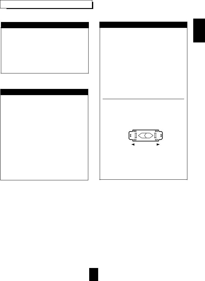
AC VOLTAGE SELECTION
This unit operates on 110-220 V AC. The AC voltage selector switch on the rear panel is set to the voltage that prevails in the area to which the unit is shipped. Before connecting the power cord to your AC outlet, make sure that the setting position of this switch matches your line voltage. If not, it must be set to your voltage in accordance with the following direction.
AC voltage selector switch
AC 220 V |
|
|
|
|
AC 110 V |
|
|
|
|
||
|
|
|
|
||
|
|
|
|
Move switch lever to match your line voltage with a small screwdriver or other pointed tool.
ENGLISH
3

ENGLISH
CONTENTS |
|
Introduction |
|
UNPACKING AND INSTALLATION ....................................................................................................... |
2 |
READ THIS BEFORE OPERATING YOUR UNIT................................................................................... |
3 |
System Connections........................................................................................................................................ |
5 |
Front Panel Controls ...................................................................................................................................... |
8 |
Speaker Placement.......................................................................................................................................... |
9 |
DIGI LINK III System Remote Controls................................................................................................. |
10 |
REMOTE CONTROL OPERATION RANGE.......................................................................................... |
11 |
LOADING BATTERIES............................................................................................................................ |
11 |
Operations |
|
ADJUSTING SPEAKER SETTINGS........................................................................................................ |
12 |
ADJUSTING DELAY TIMES................................................................................................................... |
14 |
LISTENING TO A PROGRAM SOURCE................................................................................................ |
15 |
SURROUND SOUND................................................................................................................................ |
18 |
ENJOYING SURROUND SOUND........................................................................................................... |
19 |
LISTENING TO RADIO BROADCASTS ................................................................................................ |
20 |
RECORDING ............................................................................................................................................. |
22 |
OTHER FUNCTIONS................................................................................................................................ |
23 |
Using the OSD |
|
CURRENT STATUS DISPLAY................................................................................................................ |
24 |
MENU SCREEN ........................................................................................................................................ |
24 |
Troubleshooting Guide ................................................................................................................................ |
27 |
Specifications.................................................................................................................................................. |
28 |
4

System Connections
When making system connections, please be certain the AC cord is not plugged into an AC outlet.
When making connections between components, please be sure to connect the white RCA plugs to the L(left) and the red RCA plugs to the R (right) jacks respectively.
Change the position of the FM indoor antenna until you get the best possible reception of your favorite FM stations. A 75 ohm outdoor FM antenna may be used to further improve the reception. Disconnect the indoor antenna before connecting the outdoor antenna.
Place the AM loop antenna as far as possible from the receiver, TV set, speaker cords and the AC input cord and set if to a direction it to a for the best reception.
If the reception is poor with the AM loop antenna, an AM outdoor antenna can be used in place of the AM loop antenna. Make connections firmly and correctly. If not, it can cause loss of sound, noise or damage to the receiver.
If the electricity fails or the AC input cord is left unplugged for about 2 weeks, the memorized contents will be lost. Memorize them again.
■ CONNECTING AUDIO COMPONENTS
Tape deck or additional audio component
PLAY(LINE OUT)
HX-PRO
B A
AUX
CD player
CD
PLAY
APE
MON.
REC
●The TAPE MONITOR connected to the LINE graphic equalizer.
■ CONNECTING VIDEO COMPONENTS
Monitor TV
S-VIDEO IN
VIDEOIN Video deck 2
S-VIDEO OUT
|
|
|
|
OUTVIDEO |
OUTAUDIO |
OUT |
|
|
|
|
|
|
S-VIDEO |
|
|
|
|
|
|
MON. |
|
|
|
|
|
VIDEO |
VCR 2 |
|
|
|
|
|
MON. |
|
|
|
|
|
|
OUT |
|
|
|
|
S-VIDEO |
|
|
DVD |
|
|
|
AUX |
|
|
|
|
COAXIAL 1 |
|
|
MON. |
|
|
|
|
|
CD |
|
|
|
|
L R |
|
|
OUT |
|
|
AM |
FRONT |
VIDEO |
PLAY |
VCR 2 |
|
IN |
LOOP |
PRE |
MON. |
|
|
|
|
|
OUT |
OUT |
TAPE |
|
|
VCR 2 |
|
REAR |
|
MON. |
|
|
VCR 1 |
|
COAXIAL 2 |
|
REC |
DVD |
|
FM |
SUB |
CENTER |
OPTICAL 1 |
IN |
OUT |
75Ω |
WOOFER |
|
VCR 2 |
||
|
|
|
|
VCR 1 |
DVD |
OUT
IN
VCR1
OUT
VIDEO |
L |
R |
■
FM
(OUTDOOR ANTENNA)
FM
(INDOOR ANTENNA)
300 ohm feeder
75Ω
SUPPLIED ADAPTOR
|
Video deck 1 |
IN AUDIO |
|
VIDEO IN |
AUDIO OUT |
||
|
|||
VIDEO OUT |
|
S-VIDEO IN |
|
|
DVD player |
S-VIDEO OUT |
|
|
|
||
VIDEO OUT |
|
AUDIO OUT |
|
|
|
S-VIDEO OUT |
●The VCR 2(or DVD) jacks may also be connected to an additional video component such as a cable TV tuner, a LD player or satellite system.
●Use the S-VIDEO jacks to make connections to video components with S-VIDEO IN/OUT jacks. A signal input into the S-VIDEO jack will be output in only the S- VIDEO jack and a signal input into the normal VIDEO jack will be output in only the normal VIDEO jack.
ENGLISH
5

ENGLISH
■ CONNECTING SPEAKERS
|
Front right |
Front left |
|
|
|
|
|
|
|
|
|
|
|
|
|
|
|
|
|
|
|
|
|
|
|
|
SER. NO |
|
|
|
|
|
|
|
AUX |
|
|
|
|
|
|
|
|
|
|
S-VIDEO |
|
|
|
|
|
|
COAXIAL 1 |
|
|
MON. |
|
|
|
|
|
|
|
|
CD |
|
|
|
|
|
L |
R |
|
|
|
OUT |
FRONT |
|
|
|
|
|
|
|
|
|
SPEAKERS |
|
|
AM |
|
FRONT |
|
VIDEO |
PLAY |
VCR 2 |
(8Ω) |
|
|
LOOP |
PRE |
|
|
MON. |
|
|
|
|
Rear |
|
OUT |
|
|
OUT |
TAPE |
|
|
|
|
|
|
REAR |
|
|
MON. |
|
|
|
|
|
|
|
COAXIAL 2 |
|
REC |
DVD |
|
R |
|
|
|
|
|
|
|
|
|
|
|
FM |
SUB |
CENTER |
OPTICAL 1 |
|
|
|
|
|
right |
75Ω |
WOOFER |
|
VCR 2 |
IN |
REAR |
|
|||
|
|
|
|
|
|
VCR 1 |
SPEAKERS |
|
|
|
|
|
|
|
|
(8Ω) |
|
||
|
|
FRONT |
|
|
|
OUT |
|
|
|
|
|
|
|
|
DVD |
|
|
|
|
|
ANTENNA |
|
|
|
|
|
|
|
|
|
6-CH |
REAR |
|
|
|
|
|
|
|
|
DIRECT |
OPTICAL 2 |
|
|
|
|
|
|
|
|
INPUT |
|
|
|
IN |
|
|
|
|
|
|
|
DIGITAL |
|
|
|
|
|
|
|
|
|
INPUTS |
|
VCR1 |
|
|
|
|
FRONT
SPEAKERS (8Ω)
R L
REAR
SPEAKERS (8Ω)
Rear left
CENTER SPEAKER(8Ω)
Center
■ CONNECTING DIGITAL INPUTS
COAXIAL 1 |
Component with |
|
|
|
COAXIAL DIGITAL OUT |
|
Component with |
COAXIAL 2 |
COAXIAL DIGITAL OUT |
OPTICAL 1 |
Component with |
|
|
|
OPTICAL DIGITAL OUT |
|
Component with |
OPTICAL 2 |
OPTICAL DIGITAL OUT |
DIGITAL
INPUTS
●The COAXIAL or the OPTICAL DIGITAL OUTs of the components that are connected to "CD", "VCR2" and "DVD" of this unit can be connected to these DIGITAL INPUTS.
●A digital input should be connected to the components such as LD player, CD player or DVD player, etc. capable of outputing DTS Digital Suuround, Dolby Digital(AC-3) or PCM format digital signals.
●For details, refer to the operating instructions of the component connected.
●When making the COAXIAL DIGITAL connection, be sure to use a 75Ω COAXIAL cord, not a conventional AUDIO cable.
■ CONNECTING SYSTEM CONTROL
Sherwood component with DIGI LINK II or III
CD player
System Tape deck control
cord
Graphic equalizer
DIGI-LINK
●Connect this jack to the DIGI LINK jack of the external Sherwood component that uses the DIGI LINK II or III remote control system.
6

■ PRE OUT connections
L |
R |
Power amplifier |
|
|
|
|
FRONT |
|
PRE |
|
|
OUT |
|
Front speakers |
|
REAR |
|
SUB |
CENTER |
|
WOOFER |
|
|
|
|
|
|
|
Power amplifier |
|
|
Rear speakers |
|
|
Power amplifier |
|
|
Center speaker |
|
|
Powered subwoofer |
●Use these jacks when adding additional amplifiers.
●Connect the PRE OUT jacks to the powered speakers or the power amplifiers connected to speakers respectively.
●To emphasize the deep bass sounds, connect a powered subwoofer.
■ CONNECTING 6 CH DIRECT INPUTS
|
FRONT CH OUT |
|
|
FRONT |
|
|
REAR |
|
6-CH |
CH OUT |
6 CH decoder |
DIRECT |
REAR |
|
INPUT |
|
|
SUB |
CENTER |
|
WOOFER |
|
|
|
|
|
L |
R |
|
CENTER CH OUT
SUBWOOFER CH OUT
●Use these jacks to connect the corresponding analog outputs of 6 CH decoder or DVD player with 6 CH output for Dolby Digital or DTS, etc.
(For details, see the operator's manual of the component to be connected.)
ENGLISH
■ AC INPUT CORD
Plug this cord into a wall AC outlet.
|
|
|
|
|
SER. NO |
|
|
|
|
|
|
|
|
|
AUX |
|
|
|
AC INPUT |
|
|
|
|
|
|
|
S-VIDEO |
|
|
|
120V~60Hz |
|
|
|
|
|
|
COAXIAL 1 |
|
MON. |
|
|
|
|
|
|
|
|
|
|
CD |
|
|
|
|
|
|
|
|
L |
R |
|
|
OUT |
FRONT |
|
|
|
|
|
|
|
|
|
|
|
|
|
|
C A U T I O N |
|
|
|
|
|
|
|
|
SPEAKERS |
MODEL NO. RVD-9090R |
|
|
|
|
|
|
FRONT |
VIDEO |
PLAY |
VCR 2 |
(8Ω) |
R I S K O F E L E C T R I C S H O C K |
|
|
|||
|
|
|
|
|
|
D O N O T O P E N |
|
|
|||
|
|
MON. |
|
|
|
AUDIO/VIDEO RECEIVER |
|
|
|
|
|
|
|
OUT |
TAPE |
|
|
|
W A R N I N G : " S H O C K |
H A Z A R D - D O |
N O T |
O P E N " |
|
|
|
|
MON. |
|
|
|
|||||
|
REAR |
|
|
|
|
|
AV I S : " R I S Q U E |
D E |
C H O C - E L E C T R I Q U E - N E P A S |
||
|
|
COAXIAL 2 |
REC |
DVD |
R |
L |
O U V R I R " |
|
|
|
|
|
|
|
|
"Manufactured under license from Digital |
Manufactured under license from Dolby Laboratories. |
|||||||
CENTER |
OPTICAL 1 |
|
|
Theater Systems, Inc. US Pat. No. 5,451,942 |
"Dolby", "PRO LOGIC" and the double-D symbol are |
|||||||
IN |
|
and other world-wide patents issues and |
trademarks of Dolby Laboratories. Confidential |
|||||||||
|
|
VCR 2 |
REAR |
pending. "DTS", "DTS Digital surround", are |
Unpublished Works. ©1992-1997 Dolby Laboratories, |
|||||||
|
|
VCR 1 |
SPEAKERS |
trademarks of Digital Theater Systems, Inc. |
Inc. All rights reserved. |
|
|
|
||||
|
|
|
(8Ω) |
Copyright 1996 Digital Theater System, Inc. |
|
|
|
E85649 |
|
|
||
FRONT |
|
OUT |
|
All Rights Reserved. |
|
|
|
|
|
|||
|
|
DVD |
|
|
|
|
|
|
29Z3 |
|
|
|
|
|
|
|
|
|
|
LISTED |
|
|
|||
|
|
|
|
|
|
|
|
AUDIO EQUIPMENT |
|
|||
REAR |
OPTICAL 2 |
IN |
|
AC OUTLET |
|
|
|
|
|
|
C |
|
|
|
|
|
|
|
|
|
|
|
|
|
|
|
DIGITAL |
|
|
|
T h i s d e v i c e |
c o m p l i e s |
w i t h |
P a r t 1 5 o f |
t h e F C C R u l e s . |
|||
CENTER |
INPUTS |
VCR1 |
|
|
O p e r a t i o n i s |
s u b j e c t |
t o |
t h e |
f o l l o w i n g |
t w o c o n d i t i o n s : |
||
|
|
|
|
( 1 ) T h i s |
d e v i c e |
m a y n o t |
c a u s e h a r m f u l |
i n t e r f e r e n c e , a n d |
||||
|
|
OUT |
|
|
( 2 ) t h i s |
d e v i c e |
m u s t a c c e p t |
a n y i n t e r f e r e n c e r e c e i v e d , |
||||
L |
R |
|
DIGI-LINK |
CENTER SPEAKER(8Ω) |
SWITCHED |
i n c l u d i n g i n t e r f e r e n c e t h a t m a y c a u s e u n d e s i r e d o p e r a t i o n . |
|
|
|
|
120V~60Hz |
|
|
|
VIDEO |
L |
R |
|
100W 1A MAX |
|
■SWITCHED AC OUTLET
●This outlet is switched on(power on mode) and off(standby mode) according to power controls as follows(Maximum total capacity is 1A, 100W):
Standby mode – switched AC outlet off
Power on mode – switched AC outlet on
7
ENGLISH
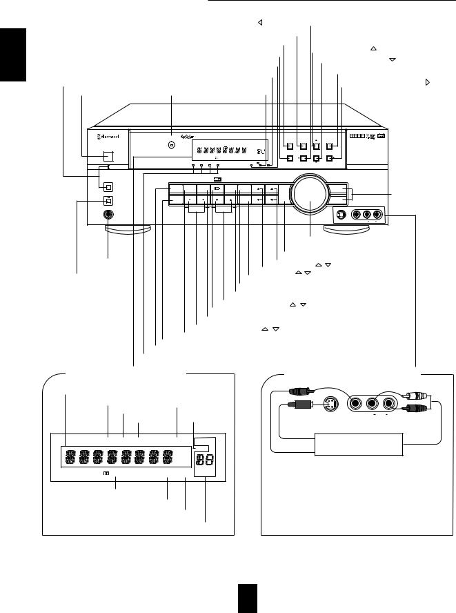
Front Panel Controls
DYNAMIC RANGE/CURSOR LEFT( ) BUTTON/INDICATOR
BAND BUTTON
ON SCREEN DISPLAY BUTTON/INDICATOR
|
FRONT/REAR VCR 2 SELECT BUTTON/INDICATOR |
|
FM MODE/CURSOR UP( |
) BUTTON |
||||||||||
|
|
CINEMA EQ/CURSOR DOWN( |
) BUTTON/INDICATOR |
|||||||||||
|
|
|
|
|
|
DTS INDICATOR |
|
|||||||
|
|
|
|
|
|
|
|
|
|
|
|
|||
STANDBY BUTTON/ |
|
|
|
TONE DIRECT INDICATOR |
|
|
MEMORY/ENTER BUTTON |
|
||||||
|
|
|
|
|
|
|
|
|
||||||
INDICATOR |
|
|
|
|
DOLBY DIGITAL |
|
|
SPEAKER MODE/CURSOR RIGHT( ) BUTTON |
||||||
POWER SWITCH |
REMOTE SENSOR |
|
|
|
|
|
|
|
|
|||||
|
|
(AC-3) INDICATOR |
|
|
|
|
|
|
||||||
|
AUDIO/VIDEO RECEIVER RVD-9090R |
|
|
|
|
|
|
|
|
|
T D A S |
|
|
|
|
|
|
|
|
|
|
|
|
|
|
|
|
|
|
|
|
|
|
|
ST TUNED AUTO |
TAPE M PRESET |
ON SCREEN |
BAND |
FM MODE |
MEMO/ENTER |
|
|
|
|
|
|
|
|
|
|
|
|
|
|
|
|
|||
|
R |
|
|
|
|
|
MEM |
|
|
|
|
|
|
|
POWER |
|
|
|
|
|
dB |
|
|
|
|
|
|
|
|
ON/OFF |
|
|
|
|
|
kHz |
|
|
|
|
|
|
|
|
|
|
|
|
|
|
MHz |
|
VCR 2 SEL. |
DYNAMIC RANGE CINEMA EQ |
SPEAKER MODE |
|
|
|
|
|
|
|
|
|
|
|
ms |
|
|
|
|
|
|
|
|
|
|
|
|
Pro Logic |
THEATER HALL |
SLEEP |
|
|
|
|
|
|
|
|
|
OPTICAL 1 |
OPTICAL 2 COAXIAL 1 |
COAXIAL 2 |
DTS |
DIGITAL |
DIRECT |
|
|
|
|
|
|
|
STANDBY |
|
|
|
|
|
|
|
|
MASTER VOLUME |
|
|
|
|
|
STANDBY |
|
|
|
|
|
|
BASS |
TREBLE |
|
|
INPUT SELECTOR |
|
|
|
|
DIRECT |
DIGITAL |
6 CHANNEL |
|
DSP |
STEREO |
|
|
|
|
AUDIO |
|
|
AUDIO/VIDEO INPUT |
|
|
INPUTS |
DIRECT |
|
MODE |
|
|
|
|
|
|
|
|
|
|
|
|
|
|
|
|
|
TAPE |
|
|
|
|
|
|
SPEAKER |
|
|
|
|
|
|
|
|
|
|
|
|
SELECTOR BUTTONS |
|
|
|
|
|
|
|
|
MONITOR |
|
|
|
|
|
||
|
|
|
|
|
|
|
|
|
|
|
VIDEO |
|
|
|
|
|
|
|
|
|
|
|
|
|
|
|
|
|
|
PHONES |
CH SELECTOR |
CHANNEL LEVEL |
|
TUNING/PRESET |
MODE |
|
|
|
|
S-VIDEO |
VCR 2 INPUT |
|
|
|
|
|
|
|
|
|
|
|
|
|
|
VIDEO |
L AUDIO R |
|
|
|
MASTER VOLUME |
|
|
CONTROL KNOB |
|
|
TAPE MONITOR BUTTON |
|
HEADPHONE JACK |
TREBLE UP/DOWN( / ) BUTTONS |
|
|
BASS UP/DOWN( |
/ ) BUTTONS |
SPEAKER BUTTON/ |
TUNING/PRESET MODE BUTTON |
|
INDICATOR |
STEREO BUTTON |
|
|
DSP MODE BUTTON |
|
|
TUNING/PRESET UP/DOWN( / |
) BUTTONS |
|
DTS/DOLBY SURROUND BUTTON |
|
|
6 CHANNEL DIRECT BUTTON |
|
|
CHANNEL LEVEL UP/DOWN( / ) BUTTONS |
|
|
DIGITAL INPUT BUTTON |
|
|
CHANNEL SELECTOR BUTTON |
|
|
TONE DIRECT BUTTON |
|
|
DIGITAL INPUT INDICATORS |
|
■ FLUORESCENT DISPLAY
INPUT, FREQUENCY, VOLUME LEVEL, OPERATING INFORMATIONS, etc.
STEREO INDICATOR |
TAPE MONITOR INDICATOR |
|
|
TUNED INDICATOR |
|
AUTO INDICATOR MEMORY INDICATOR |
|
RDS RT TIMER 12 ST TUNED AUTO VCR12V-CD TAPE |
M |
PRESET |
||
|
|
dB |
|
MEM |
|
|
|
|
|
|
|
kHz |
|
|
|
|
MHz |
|
|
EON TP TA PTY |
|
THEATER HALL |
ms |
|
Pro Logic |
SLEEP |
|||
DOLBY(
 ) PRO LOGIC INDICATOR
THEATER INDICATOR
HALL INDICATOR
PRESET NUMBER, SLEEP TIME, DELAY TIME DISPLAY
■ FRONT VCR 2 INPUT JACKS
S-VIDEO |
VCR 2 INPUT |
VIDEO |
L AUDIO R |
Additional video component
S-VIDEO OUT
AUDIO OUT
VIDEO OUT
●The front VCR 2 input jacks may be also connected to an additional video component such as a camcorder, a video deck or a video game player, etc.
●Use the S-VIDEO jack to make connection to video component with the S-VIDEO OUT jack.
A signal input into the S-VIDEO jack will be output in only the S-VIDEO jack and a signal input into the normal VIDEO jack will be output in only the normal VIDEO jack.
8

Speaker Placement
To obtain the best surround sound effect in your home, place the speakers as follows;
Front speakers: Place each front speaker about 1m (40 ) from the TV set. Center speaker: Place the center speaker either above or below the TV set
to assure good visualization of center channel program. Rear speakers: Place the rear speakers approximately 1m above the ear
level of a seated listener on the direct left and right of them or slightly behind.
Subwoofer: Reproduces powerful deep bass sounds. Place a powered subwoofer anywhere in the front as desired.
The ideal surround system needs all the speakers listed above.
To accurately reproduce DTS digital surround, center and rear speakers as well as front speakers should be full range speakers.
To enjoy the surround sound best, the speakers to be connected are as follows;
FRONT |
TV set |
FRONT |
LEFT |
|
RIGHT |
SUB |
|
CENTER |
WOOFER |
|
SPEAKER |
REAR |
REAR |
LEFT |
RIGHT |
Speakers Modes |
DTS |
Dolby Digital(AC-3) |
Dolby Pro Logic |
Other Surround |
Stereo |
6 CH DIRECT |
Front |
Yes |
Yes |
Yes |
Yes |
Yes |
Yes |
|
|
|
|
|
|
|
Center |
Yes |
Yes |
Yes |
Optional |
- |
Yes |
|
|
|
|
|
|
|
Rear |
Yes |
Yes |
Yes |
Yes |
- |
Yes |
Subwoofer |
Yes |
Yes |
Optional |
Optional |
Optional |
Yes |
Note:To avoid interference with the TV picture, use only magnetically shielded center and front speakers.
ENGLISH
9
 Loading...