


 cover 2008.8.21 12:21 PM 2
OPERATING INSTRUCTIONS
RD-6513
AUDIO/VIDEO RECEIVER
 RD-6513(A) 2008.8.21 12:19 PM 3
IMPORTANT SAFETY INSTRUCTIONS
1.Read these instructions.
2.Keep these instructions.
3.Heed all warnings.
4.Follow all instructions.
5.Do not use this apparatus near water.
6.Clean only with dry cloth.
7.Do not block any ventilation openings.
Install in accordance with the manufacturer’s instructions.
8.Do not install near any heat sources such as radiators, heat registers, stoves, or other apparatus (including amplifiers) that produce heat.
9.Do not defeat the safety purpose of the polarized or grounding-type plug. A polarized plug has two blades with one wider than the other.
A grounding type plug has two blades and a third grounding prong. The wide blade or the third prong are provided for your safety. If the provided plug does not fit into your outlet, consult an electrician for replacement of the obsolete outlet.
10.Protect the power cord from being walked on or pinched particularly at plugs, convenience receptacles, and the point where they exit from the apparatus.
11.Only use attachments accessories specified by the manufacturer.
12.Use only with the cart, stand, tripod, bracket, or table specified by the manufacturer, or sold with the apparatus.
When a cart is used, use caution when moving the cart/apparatus combination to avoid injury from tip-over.
PORTABLE CART WARNING
13.Unplug this apparatus during lightning storms or when unused for long periods of time.
14.Refer all servicing to qualified service personnel.
Servicing is required when the apparatus has been damaged in any way, such as power-supply cord or plug is damaged, liquid has been spilled or objects have fallen into the apparatus, the apparatus have been exposed to rain or moisture, does not operate normally, or has been dropped.
ENGLISH
3
 RD-6513(A) 2008.8.21 12:19 PM 4
ENGLISH
Introduction
READ THIS BEFORE OPERATING YOUR UNIT
|
|
|
|
This symbol is intended to alert the user to the presence |
|
|
|
|
of uninsulated "dangerous voltage" within the product's |
|
|
|
|
enclosure that may be of sufficient magnitude to |
|
|
|
|
constitute a risk of electric shock to persons. |
CAUTION : |
TO REDUCE THE RISK OF ELECTRIC SHOCK, |
|
|
|
|
|
|
||
|
|
This symbol is intended to alert the user to the presence |
||
DO NOT REMOVE COVER (OR BACK). NO |
|
|
||
|
USER-SERVICEABLE PARTS INSIDE. REFER |
|
|
of important operating and maintenance (servicing) |
|
SERVICING TO QUALIFIED SERVICE |
|
|
instructions in the literature accompanying the appliance. |
|
PERSONNEL. |
|
|
|
WARNING : TO REDUCE THE RISK OF FIRE OR ELECTRIC SHOCK,
DO NOT EXPOSE THIS APPLIANCE TO RAIN OR MOISTURE.
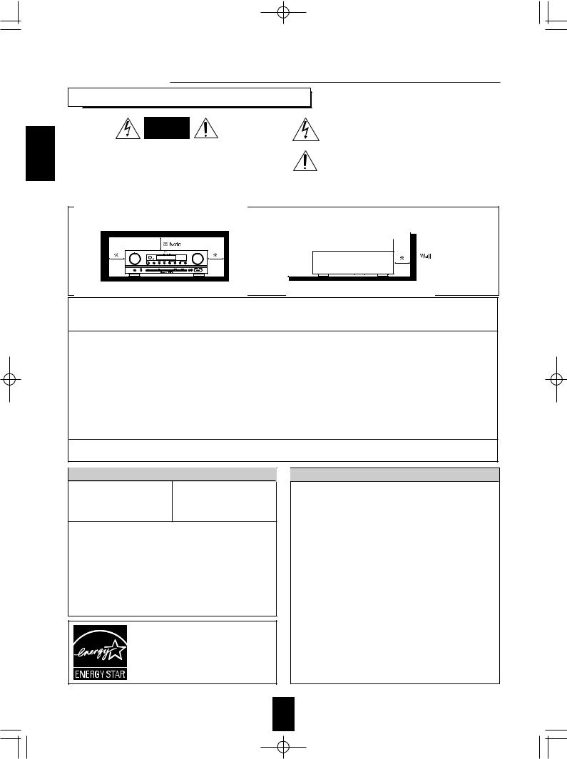
Caution regarding installation
Note : For heat dispersal, do not install this unit in a confined space such as a bookcase or similar enclosure.
Do not block ventilation openings or stack other equipment on the top.
Note to CATV System Installer :
This reminder is provided to call the CATV system installer’s attention to Article 820-40 of the NEC that provides guidelines for proper grounding and, in particular, specifies that the cable ground shall be connected to the grounding system of the building, as close to the point of cable entry as practical.
FCC INFORMATION
This equipment has been tested and found to comply with the limits for a Class B digital device, pursuant to Part 15 of the FCC Rules. These limits are designed to provide reasonable protection against harmful interference in a residential installation. This equipment generates, uses and can radiate radio frequency energy and, if not installed and used in accordance with the instructions, may cause harmful interference to radio communications. However, there is no guarantee that interference will not occur in a particular installation. If this equipment does cause harmful interference to radio or television reception, which can be determined by turning the equipment off and on, the user is encouraged to try to correct the interference by one or more of the following measures:
•Reorient or relocate the receiving antenna.
•Increase the separation between the equipment and receiver.
•Connect the equipment into an outlet on a circuit different from that to which the receiver is connected.
•Consult the dealer or an experienced radio/TV technician for help.
Caution : Any changes or modifications in construction of this device which are not expressly approved by the party responsible for compliance could void the user’s authority to operate the equipment.
This Class B digital apparatus complies with Canadian ICES-003.
Cet appareil numérique de la Classe B est conforme à la norme NMB-003 du Canada.
FOR YOUR SAFETY
U.S.A
120 V
CANADA
Units shipped to the U.S.A and CANADA are designed for operation on 120 V AC only.
Safety precaution with use of a polarized AC plug.
However, some products may be supplied with a nonpolarized plug.
CAUTION |
: To prevent electric shock, match wide blade of |
|
plug to wide slot, fully insert. |
ATTENTION : Pour éviter chocs électriques, introduire la lame la plus large de la fiche dans la borne
correspondante de la prise et pousser jusqu’ au fond.
ENERGY STAR is a U.S. registered mark. As an ENERGY STAR Partner, Sherwood has determined that this product meets the ENERGY STAR guidelines for energy efficiency.
CAUTION
•Leave a space around the unit for sufficient ventilation.
•Avoid installation in extremely hot or cold locations, or in an area that is exposed to direct sunlight or heating equipment.
•Keep the unit free from moisture, water, and dust.
•Do not let foreign objects in the unit.
•The ventilation should not be impeded by covering the ventilation openings with items, such as newspapers, table-cloths, curtains, etc.
•No naked flame sources, such as lighted candles, should be placed on the unit.
•Please be care the environmental aspects of battery disposal.
•The unit shall not be exposed to dripping or splashing for use.
•No objects filled with liquids, such as vases, shall be placed on the unit.
•Do not let insecticides, benzene, and thinner come in contact with the set.
•Never disassemble or modify the unit in any way.
■Notes on the AC power cord and the wall outlet.
•The unit is not disconnected from the AC power source(mains) as long as it is connected to the wall outlet, even if the unit has been turned off.
•To completely disconnect this product from the mains, disconnect the plug from the wall socket outlet.
•When setting up this product, make sure that the AC outlet you are using is easily acceptable.
•Disconnect the plug from the wall outlet when not using the unit for long periods of time.
4
 RD-6513(A) 2008.8.21 12:19 PM 5
CONTENTS |
|
• IMPORTANT SAFETY INSTRUCTIONS .............................................................................................................................. |
3 |
Introduction |
|
• READ THIS BEFORE OPERATING YOUR UNIT ................................................................................................................. |
4 |
System Connections ......................................................................................................................................................... |
6 |
Front Panel Controls ....................................................................................................................................................... |
11 |
Remote Controls ............................................................................................................................................................... |
13 |
• REMOTE CONTROL OPERATION RANGE ....................................................................................................................... |
14 |
• LOADING BATTERIES ....................................................................................................................................................... |
14 |
Operations |
|
• LISTENING TO A PROGRAM SOURCE ............................................................................................................................ |
15 |
• SURROUND SOUND .......................................................................................................................................................... |
18 |
• ENJOYING SURROUND SOUND ...................................................................................................................................... |
19 |
• LISTENING TO RADIO BROADCASTS ............................................................................................................................. |
24 |
• RECORDING ....................................................................................................................................................................... |
26 |
• OTHER FUNCTIONS .......................................................................................................................................................... |
28 |
System Setup ..................................................................................................................................................................... |
29 |
• SETTING THE SYSTEM .................................................................................................................................................... |
31 |
• SETTING THE INPUT ......................................................................................................................................................... |
33 |
• SETTING THE SPEAKER SETUP ...................................................................................................................................... |
34 |
• SETTING THE CH LEVEL .................................................................................................................................................. |
39 |
• SETTING THE PARAMETER ............................................................................................................................................. |
41 |
Troubleshooting Guide ................................................................................................................................................... |
43 |
Specifications .................................................................................................................................................................... |
44 |
ENGLISH
5

 RD-6513(A) 2008.8.21 12:19 PM 6
System Connections
•Do not plug the AC input cord into the wall AC outlet until all connections are completed.
•Be sure to observe the color coding when connecting audio, video and speaker cords.
•Make connections firmly and correctly. If not, it can cause loss of sound, noise or damage to the receiver.
ENGLISH |
1. CONNECTING ANTENNAS
•Change the position of the FM indoor antenna until you get the best reception of your favorite FM stations.
•A 75Ω outdoor FM antenna may be used to further improve the reception. Disconnect the indoor antenna before replacing it with the outdoor one.
•Place the AM loop antenna as far as possible from the receiver, TV set, speaker cords and the AC input cord and set it to a direction for the best reception.
•If the reception is poor with the AM loop antenna, an AM outdoor antenna can be used in place of the AM loop antenna.
6

 RD-6513(A) 2008.8.21 12:19 PM 7
2. CONNECTING VIDEO COMPONENTS
ENGLISH
•The jacks of VIDEO 1 may also be connected to a DVD recorder or other digital video recording component. For details, refer to the operating instructions of the component to be connected.
•The jacks of VIDEO 2 can also be connected to an additional video component such as a cable TV tuner, an LD player or satellite system.
•There are three types of video jacks (COMPONENT, S-VIDEO, (composite) VIDEO) for analog video connections and the HDMI connectors for digital video and audio connections. Connect them to the corresponding video jacks according to their capability.
•For your reference, the excellence in picture quality is as follows : "HDMI” > "COMPONENT" > "S-VIDEO" > "(composite) VIDEO".
•When making COMPONENT VIDEO connections, connect "Y" to "Y", "PB/CB" to "CB"(or "B-Y", "PB") and "PR/CR" to "CR"(or "R-Y", "PR").
Note :
•When recording video program sources through VIDEO 1 OUT jacks or viewing video program sources through MONITOR
OUT jack, you must use the same type of video jacks that you did connect to video playback components such as DVD player, LD player, etc.
HDMI (High Definition Multimedia Interface) connection : (*)
•You can connect the source component (DVD player, etc.) to the display component (TV, projector, etc.) through this receiver with using a commercially available HDMI cord.
•The HDMI connection can carry uncompressed digital video signals and digital audio signals.
•This receiver can output digital video and digital audio signals from the HDMI MONITOR OUT of this receiver without passing through any circuits as they were input into the HDMI IN(, meaning the audio signals which are input into the HDMI IN cannot be reproduced on this receiver).
•This receiver is HDMI Ver. 1.3 compatible.
•HDMI, the HDMI logo and High-Definition Multimedia Interface are trademarks or registered trademarks of HDMI licensing LLC.
Notes :
•Depending on the connected component, unreliable signal transfer may happen.
(For details, refer to the operating instruction of your component.)
•For stable signal transfer, we recommend using HDMI cords that are a maximum of 5 meters in length.
7
 RD-6513(A) 2008.8.21 12:19 PM 8
3. CONNECTING AUDIO COMPONENTS
• The TAPE IN/OUT jacks can be connected to audio recording equipment such as a tape deck, an MD recorder, etc.
ENGLISH
4. CONNECTING EXTERNAL INs
•Use these jacks to connect the corresponding analog outputs of 6 CH decoder or DVD player with 6 CH output for Dolby Digital or DTS, etc.
(For details, see the operator's manual of the component to be connected.)
8
 RD-6513(A) 2008.8.21 12:19 PM 9
5. CONNECTING DIGITAL INs
•The OPTICAL and the COAXIAL DIGITAL OUTs of the components that are connected to CD and VIDEO 1 ~
VIDEO 2 of this unit can be connected to these DIGITAL INs.
• A digital input should be connected to the components such as a CD player, LD player, DVD player, etc. capable of outputting DTS Digital Surround, Dolby Digital or PCM format digital signals, etc.
• For details, refer to the operating instructions of the component connected.
• When making the COAXIAL DIGITAL connection, be sure to use a 75 Ω COAXIAL cord, not a conventional AUDIO cord.
•All of the commercially available optical fiber cords cannot be used for the equipment. If there is an optical fiber cord which cannot be connected to your equipment, consult your dealer or nearest service organization.
Note :
• Be sure to make either a OPTICAL or a COAXIAL DIGITAL connection on each component. (You don’t need to do both.)
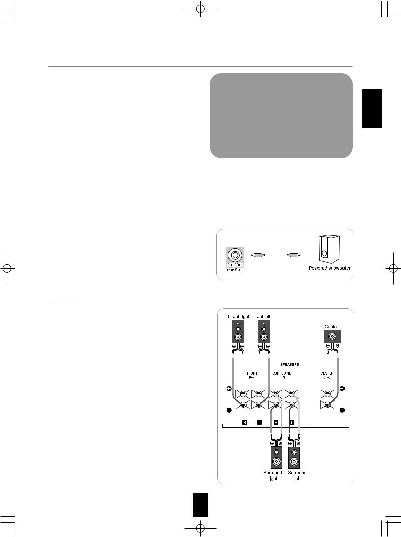
6. CONNECTING SUBWOOFER PRE OUT
• To emphasize the deep bass sounds, connect a powered subwoofer.
7. CONNECTING SPEAKERS
• Be sure to connect speakers firmly and correctly according to the channel(left and right) and the polarity(+ and -). If the connections are faulty, no sound will be heard from the speakers, and if the polarity of the speaker connection is incorrect, the sound will be unnatural and lack bass.
•For installing the speakers, refer to "Speaker placement" on page 10.
• After installing the speakers, first adjust the speaker settings according to your environment and speaker layout.
(For details, refer to "SETTING THE SPEAKER SETUP" on page 34.)
Caution :
• Be sure to use the speakers with the impedance of 6 ohms or above.
• Do not let the bare speaker wires touch each other or any metal part of this unit. This could damage this unit and/or the speakers.
ENGLISH
9
 RD-6513(A) 2008.8.21 12:19 PM 10
ENGLISH
8. AC INPUT CORD
•Plug the cord into a wall AC outlet.
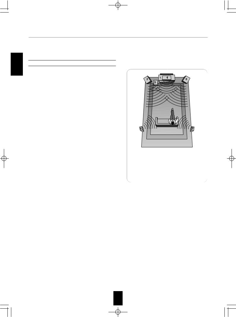
Speaker placement
Ideal speaker placement varies depending on the size of your room and the wall coverings, etc. The typical example of speaker placement and recommendations are as follows :
Front left and right speakers and center speaker
•Place the front speakers with their front surfaces as flush with
TV or monitor screen as possible.
•Place the center speaker between the front left and right speakers and no further from the listening position than the front speakers.
•Place each speaker so that sound is aimed at the location of the listener’s ears when at the main listening position.
Surround left and right speakers
•Place the surround speakers approximately 1 meter (40 inches) above the ear level of a seated listener on the direct left and right of them or slightly behind.
Subwoofer
•The subwoofer reproduces powerful deep bass sounds. Place a subwoofer anywhere in the front as
desired.
Notes :
•When using a conventional TV, to avoid interference with the
TV picture, use only magnetically shielded front left and right and center speakers.
•To obtain the best surround effects, the speakers except the subwoofer should be full range speakers.
1.TV or screen
2.Front left speaker
3.Front right speaker
4.Center speaker
5.Subwoofer
6.Surround left speaker
7.Surround right speaker
10
 RD-6513(A) 2008.8.21 12:19 PM 11
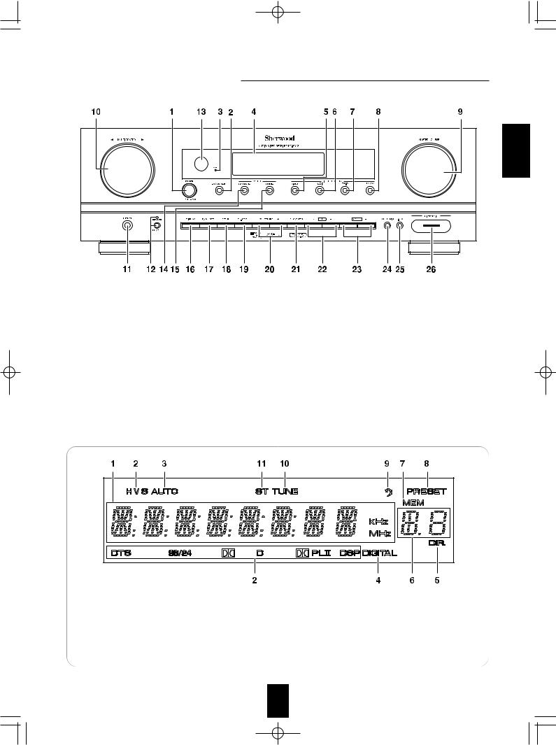
Front Panel Controls
ENGLISH |
|
|
|
|
|
|
|
1. POWER switch |
11. HEADPHONE jack |
21. MEMORY/ENTER button |
||||
2. |
POWER ON/STANDBY button |
12. |
SPEAKER button/indicator |
22. TUNING UP/DOWN (+/-) buttons |
||
3. STANDBY indicator |
13. REMOTE SENSOR |
23. PRESET UP/DOWN (+/-) buttons |
||||
4. FLUORESCENT DISPLAY |
14. SURROUND MODE button |
24. SETUP MIC JACK |
||||
|
For details, see below. |
15. |
STEREO button |
For details, see next page. |
||
5. VIDEO INPUT SELECTOR button |
16. DISPLAY button |
25. FRONT AUX IN JACK |
||||
6. |
AUDIO INPUT SELECTOR button |
17. |
DIGITAL/ANALOG MODE button |
For details, see next page. |
||
7. |
EXT.IN SELECTOR button |
18. |
SETUP button |
26. Bluetooth IN connector |
||
8. |
FM/AM button |
19. |
CHANNEL LEVEL button |
For details, see next page. |
||
9. MASTER VOLUME CONTROL knob |
20. CONTROL UP/DOWN (▲/▼) |
|
|
|
||
10. MULTI CONTROL knob ( / ) |
|
buttons |
|
|
|
|
FLUORESCENT DISPLAY
1. |
Input, frequency, volume level, operating information, etc. |
7. |
MEMORY indicator |
2. |
Surround mode indicators |
8. |
PRESET indicator |
3. |
AUTO indicator |
9. |
SLEEP indicator |
4. |
DIGITAL INPUT indicator |
10. |
TUNED indicator |
5. |
DIRECT indicator |
11. |
STEREO indicator |
6. |
Preset number, sleep time display |
|
|
11
 RD-6513(A) 2008.8.21 12:19 PM 12
SETUP MIC JACK
|
• To use Auto Setup function, connect the supplied microphone to the SETUP MIC jack.(For details, refer to "When |
|
|
selecting the AUTO SETUP" on page 35.) |
|
|
Notes: |
|
ENGLISH |
• Because the microphone for Auto Setup is designed for use with this receiver, do not use a microphone other than |
|
the one supplied with this receiver. |
||
|
• After you have completed the auto setup procedure, disconnect the microphone.
Microphone
FRONT AUX IN JACK
• The FRONT AUX IN jack can be connected to additional audio components such as an MP3 player, etc.
Note :
• When connecting this jack to an MP3 player, etc., you should use the stereo mini cord, not a mono mini cord.
Bluetooth IN CONNECTOR
•If the Bluetooth IN connector is connected to Sherwood Audio Receiver BT-R7(sold separately) with Bluetooth wireless technology, you can enjoy music wirelessly with a music player featuring Bluetooth wireless technology such as MP3 player, mobile phone, etc..
(For information on Sherwood Audio Receiver BT-R7, contact your dealer.)
•The Bluetooth word mark and logos are registered trademarks owned by Bluetooth SIG, Inc. and any use of such marks by Sherwood Corporation is under license. Other trademarks and trade names are those of their respective owners.
Notes:
•For safe operation, turn the power off before connecting or disconnecting the Audio Receiver BT-R7.
•When not using the Bluetooth IN connector, cover it with the supplied cap.
12
 RD-6513(A) 2008.8.21 12:19 PM 13
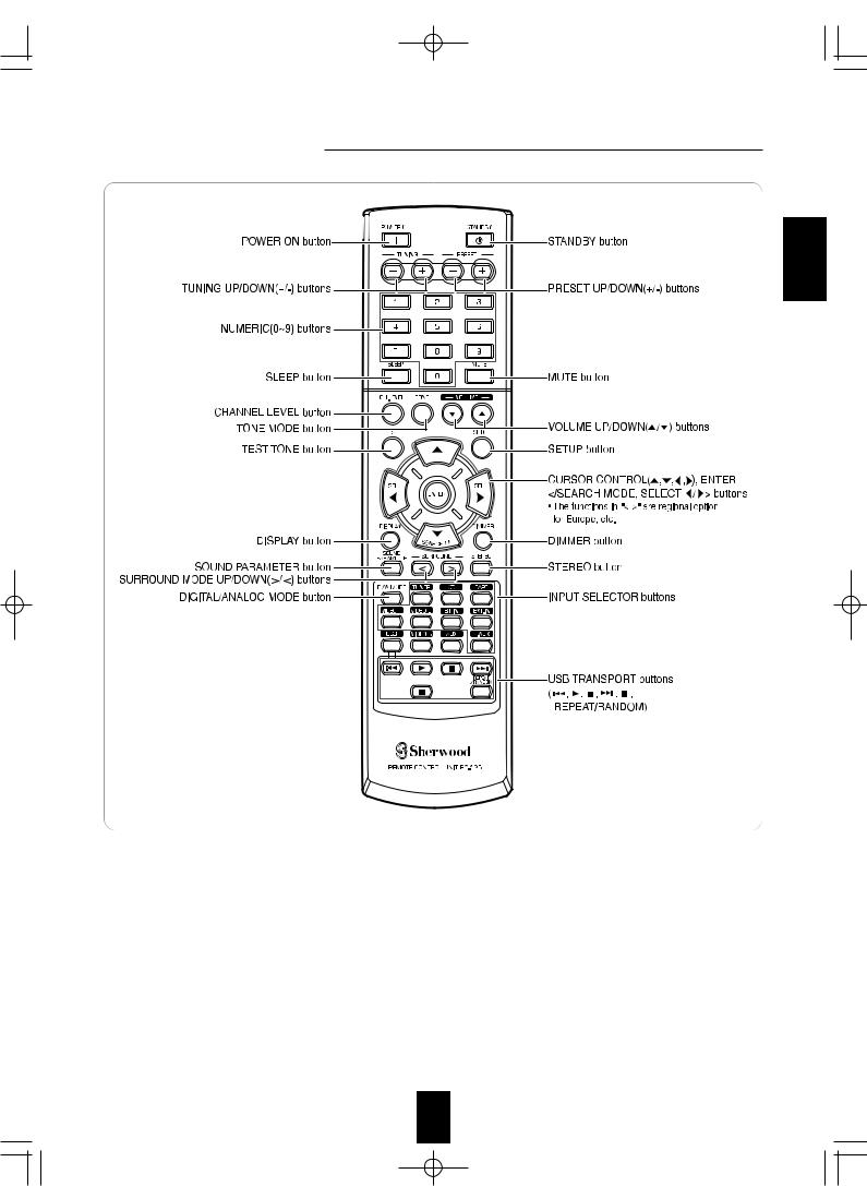
Remote Controls
ENGLISH
Note :
• Some buttons (USB, VIDEO 3, AUX and USB transport buttons) are not available for this receiver.
13

 RD-6513(A) 2008.8.21 12:19 PM 14
REMOTE CONTROL OPERATION RANGE
ENGLISH
•Use the remote control unit within a range of about 7 meters (23 feet) and angles of up to 30 degrees aiming at the remote sensor.
LOADING BATTERIES
1. Remove the cover. |
2. Load two batteries ("AAA" size, 1.5 V) matching the |
|
polarity. |
• Remove the batteries when they are not used for a long time.
• Do not use the rechargeable batteries (Ni-Cd type).
 RD-6513(A) 2008.8.21 12:19 PM 15
Operations
Note : Before operating this receiver, first set this unit as desired for optimum performance, doing the system setup procedures. (For details, refer to "System Setup" on page 29.)
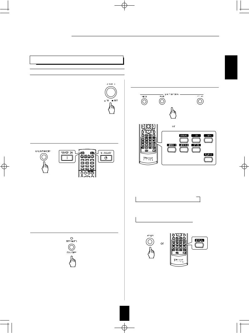
LISTENING TO A PROGRAM SOURCE
Before operation
•Enter the standby mode.
•The STANDBY indicator lights up. This means that the receiver is not
disconnected from the AC mains and a small amount of current is retained to support the operation readiness.
•To switch the power off, push the POWER switch again.
•Then the power is cut off and the STANDBY indicator goes off.
1.In the standby mode, turn the power on.
or
•Each time the POWER ON/STANDBY button on the front panel is pressed, the receiver is turned on to enter the operating mode or off to enter the standby mode.
•On the remote control, press the POWER ON button to enter the operating mode or press the STANDBY button to enter the standby mode.
•In the standby mode, if the INPUT SELECTOR button is pressed, the receiver is turned on automatically and the desired input is selected.
2. Switch the speakers on.
•Then the SPEAKER indicator lights up and the sound can be heard from the speakers connected to the speaker terminals.
•When using the headphone for private listening, press the SPEAKER button again to switch the speakers off.
3. Select the desired input source.
•Each time the "VIDEO" button on the front panel is pressed, the input source changes as follows:
VIDEO 1 ↔ VIDEO 2
•Each time the "AUDIO" button on the front panel is pressed, the input source changes as follows:
→ CD → F AUX → TAPE → BT IN
•Each time the "FM/AM" button is pressed, the band changes as follows:
→FM ST → FM MONO → AM 
When selecting the EXTERNAL IN as desired
•"EXT IN" is displayed and 6 seperate analog signals from the component connected to this input pass through the tone and volume circuits only and can be heard from your speakers.
•Selecting the desired input source to cancel the external in function.
•These analog signals can be heard only, not recorded.
ENGLISH
15
 Loading...