


O P E R A T I N G I N S T R U C T I O N S
|
AUDIO/VIDEO SURROUND RECEIVER R-863 |
|
|
|
|
|
|
|
|
|
|
|
W R A S |
||
|
|
|
|
|
|
|
|
|
|
|
|
|
|||
MULTI CONTROL |
|
|
|
|
|
|
|
|
|
|
|
|
|
MASTER VOLUME |
|
|
BAND |
T/P MODE |
|
|
|
|
|
|
|
SOURCE |
CINEMA EQ |
|
|
|
|
|
|
|
|
|
|
|
|
DIRECT |
|
|
|
||||
|
|
MULTI ROOM |
|
|
|
|
|
|
|
|
|
|
|
|
|
|
|
REMOTE SENSOR |
LOCK |
|
|
|
|
|
|
|
|
|
|
|
|
|
|
|
|
|
|
|
|
|
|
|
|
|
|
|
|
|
TUNING/PRESET |
|
|
|
|
|
|
|
ROOM2 FEED |
DYNAMIC |
|
|
|
||
|
|
|
|
|
|
|
|
|
|
RANGE |
|
|
|
||
|
POWER |
|
|
INPUT SELECTOR |
|
|
SURROUND MODE |
|
|
|
|
|
|
||
|
|
STANDBY |
AUDIO |
VIDEO |
TAPE MON. |
7.1CH DIRECT |
DECODING |
EXTRA SURR. |
STEREO |
DIGITAL/ANALOG |
|
|
|
||
|
|
|
|
|
|
|
|
|
|
|
|
|
|
||
|
|
ON/STANDBY |
|
|
|
|
|
|
|
|
|
|
|
|
|
|
|
|
|
|
|
|
|
|
6.1/7.1 |
|
|
|
|
|
|
|
ON / |
OFF |
|
|
|
|
|
|
|
|
|
|
|
|
|
PHONES |
CHANNEL |
|
|
|
|
|
|
|
|
|
|
|
|
|
|
SPEAKER |
TEST TONE |
TONE MODE |
VIDEO LABEL |
MEMO/ENTER |
|
|
|
|
|
|
|
|
|
|
|
SELECTOR |
|
|
|
|
|
|
|
|
|
|
|||||
ON/OFF |
|
|
|
|
|
|
|
|
|
|
|
|
|
|
|
|
|
|
|
|
|
|
|
|
|
|
|
OPTICAL IN |
S-VIDEO |
VIDEO |
L - AUDIO - R |
R-863
AUDIO/VIDEO SURROUND RECEIVER
ENGLISH
Introduction
UNPACKING AND INSTALLATION
Congratulations on Your Purchase!
Your new high fidelity receiver is designed to deliver maximum enjoyment and years of trouble free service. Please take a few moments to read this manual thoroughly. It will explain the features and operation of your unit and help ensure a trouble free installation. Please unpack your unit carefully. We recommend that you save the carton and packing material. They will be helpful if you ever need to move your unit and may be required if you ever need to return it for service. Your unit is designed to be placed in a horizontal position and it is important to allow at least two inches of space behind your unit for adequate ventilation and cabling convenience.
To avoid damage, never place the unit near radiators, in front of heating vents, in direct sunlight, or in excessively humid or dusty locations. Connect your complementary components as illustrated in the following section.
CAUTION |
RISK OF ELECTRIC SHOCK |
DO NOT OPEN |
CAUTION : TO REDUCE THE RISK OF |
ELECTRIC SHOCK, DO NOT |
REMOVE COVER (OR BACK). |
NO USER-SERVICEABLE PARTS |
INSIDE. REFER SERVICING TO |
QUALIFIED SERVICE PERSONNEL. |
This symbol is intended to alert the user to the presence of uninsulated "dangerous voltage" within the product's enclosure that may be of sufficient magnitude to constitute a risk of electric shock to persons.
This symbol is intended to alert the user to the presence of important operating and maintenance (servicing) instructions in the literature accompanying the appliance.
WARNING
To reduce the risk of fire or electric shock, do not expose this appliance to rain or moisture.
Caution : Do not block ventilation openings or stack other equipment on the top.
FOR U.S.A
Note to CATV System Installer: This reminder is provided to call the CATV system installer's attention to Article 820-40 of the NEC that provides guidelines for proper grounding and, in particular, specifies that the cable ground shall be connected to the grounding system of the building, as close to the point of cable entry as practical.
FCC INFORMATION
This equipment has been tested and found to comply with the limits for a Class B digital device, pursuant to Part 15 of the FCC Rules. These limits are designed to provide reasonable protection against harmful interference in a residential installation. This equipment generates, uses and can radiate radio frequency energy and, if not installed and used in accordance with the instructions, may cause harmful interference to radio communications. However, there is no guarantee that interference will not occur in a particular installation. If this equipment does cause harmful interference to radio or television reception, which can be determined by turning the equipment off and on, the user is encouraged to try to correct the interference by one or more of the following measures:
Reorient or relocate the receiving antenna. Increase the separation between the equipment and receiver.
Connect the equipment into an outlet on a circuit different from that to which the receiver is connected.
Consult the dealer or an experienced radio/TV technician for help.
CAUTION : Any changes or modifications in construction of this device which are not expressly approved by the party responsible for compliance could void the user's authority to operate the equipment.
Caution regarding placement (Except for U.S.A and Canada)
To maintain proper ventilation, be sure to leave a space around the unit (from
the largest outer dimensions including projections) equal to, or greater than, shown below.
Left and right panels: 5 cm
Rear panel: 10 cm
Top panel: 20 cm
2
READ THIS BEFORE OPERATING YOUR UNIT
FOR U.S.A AND CANADA |
.......................................120 V |
FOR YOUR SAFETY
Units shipped to the U.S.A and Canada are designed for operation on 120 Volts AC only.
Observe all safety precautions for use of a polarized AC plug. However, some products may be supplied with a non polarized plug.
CAUTION: To prevent electric shock, match wide blade of plug to wide slot, insert fully.
FOR EUROPE AND AUSTRALIA .......... |
230V/240V |
FOR YOUR SAFETY
Units shipped to Australia are designed for operation on 240 V AC only.
To ensure safe operation, the three-pin plug supplied must be inserted only into a standard three-pin power point which is effectively earthed through the normal household wiring. Extension cords used with the equipment must be three-core and be correctly wired to provide connection to earth.
Improper extension cords are a major cause of fatalities. The fact that the equipment operates satisfactorily does not imply that the power point is earthed and that the installation is completely safe. For your safety, if in any doubt about the effective earthing of the power point, consult a qualified electrician.
PAN-EUROPEAN UNIFIED VOLTAGE
All units are suitable for use on supplies 230-240 V AC.
FOR OTHER COUNTRIES ........................... |
115 V/230 V |
FOR YOUR SAFETY
Units shipped to countries other than the above countries are equipped with an AC voltage selector switch on the rear panel. Refer to the following paragraph for the proper setting of this switch.
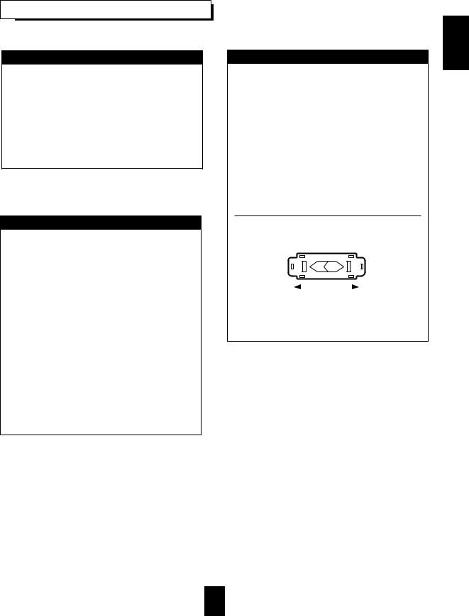
AC VOLTAGE SELECTION
This unit operates on 115/230 V AC. The AC voltage selector switch on the rear panel is set to the voltage that prevails in the area to which the unit is shipped. Before connecting the power cord to your AC outlet, make sure that the setting position of this switch matches your line voltage. If not, it must be set to your voltage in accordance with the following direction.
AC voltage selector switch
AC 230 V |
|
|
|
|
AC 115 V |
|
|
|
|
||
|
|
|
|
||
|
|
|
|
Move switch lever to match your line voltage with a small screwdriver or other pointed tool.
ENGLISH
3

ENGLISH
CONTENTS |
|
Introduction |
|
UNPACKING AND INSTALLATION ....................................................................................................... |
2 |
READ THIS BEFORE OPERATING YOUR UNIT................................................................................... |
3 |
System Connections........................................................................................................................................ |
5 |
Front Panel Controls ...................................................................................................................................... |
9 |
Universal Remote Controls |
|
DIGI LINK SYSTEM REMOTE CONTROLS ......................................................................................... |
10 |
OPERATING COMPONENTS WITH REMOTE CONTROL................................................................. |
12 |
REMOTE CONTROL OPERATION RANGE.......................................................................................... |
12 |
LOADING BATTERIES............................................................................................................................ |
12 |
ADDITIONAL INFORMATION ON REMOTE COMMAND CODES.................................................. |
13 |
ENTERING A SETUP CODE ................................................................................................................... |
14 |
Operations |
|
LISTENING TO A PROGRAM SOURCE................................................................................................ |
15 |
SURROUND SOUND................................................................................................................................ |
18 |
ENJOYING SURROUND SOUND........................................................................................................... |
21 |
LISTENING TO RADIO BROADCASTS ................................................................................................ |
25 |
RECORDING ............................................................................................................................................. |
27 |
DIGITAL AUDIO RECORDING WITH MD RECORDER..................................................................... |
28 |
OTHER FUNCTIONS................................................................................................................................ |
29 |
ROOM 2 SOURCE PLAYBACK .............................................................................................................. |
31 |
Using the OSD |
|
CURRENT STATUS DISPLAY................................................................................................................ |
32 |
OSD Menu Settings....................................................................................................................................... |
32 |
SETTING THE SPEAKER SETUP........................................................................................................... |
34 |
SETTING THE FUNCTION SELECT ...................................................................................................... |
37 |
SETTING THE SURROUND SETUP....................................................................................................... |
41 |
SETTING THE CH LEVEL TRIM............................................................................................................ |
43 |
SETTING THE ROOM2 FEED SETUP.................................................................................................... |
44 |
Troubleshooting Guide ................................................................................................................................ |
46 |
Specifications.................................................................................................................................................. |
47 |
4
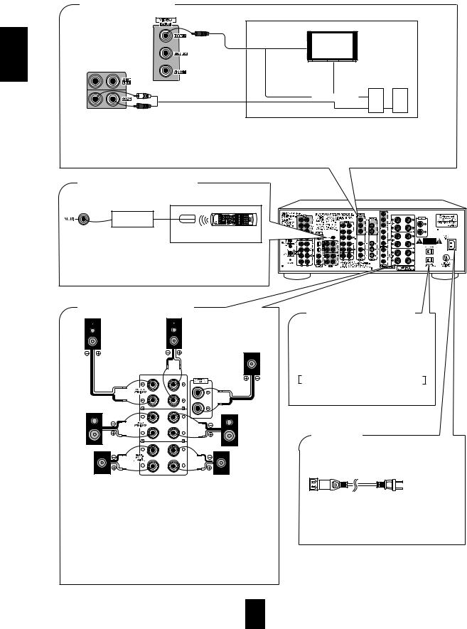
System Connections
Please be certain that the receiver is unplugged from the AC outlet before making any connections.
Be sure to connect the white RCA pin cords to the L(left) and the red RCA pin cords to the R(right) jacks when making connections.
Change the position of the FM indoor antenna until you get the best reception of your favorite FM stations. A 75Ω outdoor FM antenna may be used to further improve the reception.
Disconnect the indoor antenna before replacing it with the outdoor one.
Place the AM loop antenna as far as possible from the receiver, TV set, speaker cords and the AC input cord and set it to a direction for the best reception.
If the reception is poor with the AM loop antenna, an AM outdoor antenna can be used in place of the AM loop antenna. Make connections firmly and correctly. If not, poor connections can cause loss of sound, noise or damage to the receiver. If the electricity fails or the AC input cord is left unplugged for about two weeks, the memorized contents will be lost. Should this happen, memorize them again.
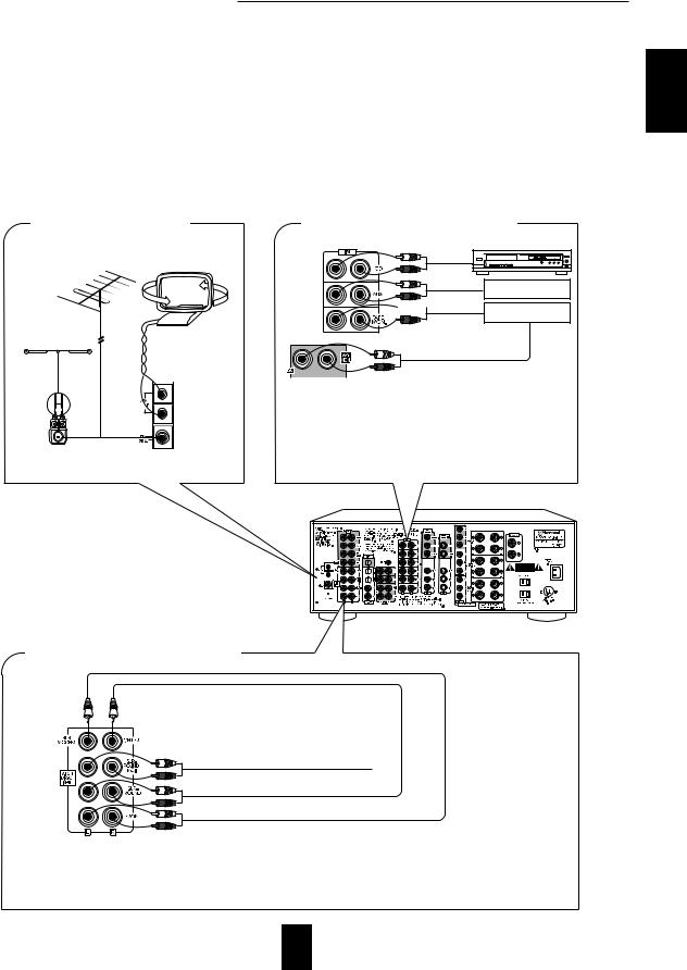
■ CONNECTING ANTENNAS
FM
(OUTDOOR ANTENNA)
FM
(INDOOR ANTENNA) |
AM loop antenna |
300 ohm feeder
SUPPLIED ADAPTOR
■ CONNECTING AUDIO COMPONENTS
CD player
Additional
audio component


 PLAY(LINE OUT) Tape deck or
MD recorder
REC(LINE IN)
•The AUX jacks may be connected to an additional audio component such as CD player or tape deck, etc.
•Connect the TAPE MONITOR IN/OUT jacks to the PLAY(LINE OUT) / REC(LINE IN) jacks of tape deck, MD recorder or CD recorder.
•The TAPE MONITOR IN/OUT jacks may also be connected to the LINE OUT/IN jacks of an optional graphic equalizer.
ENGLISH
■ CONNECTING 7.1CH DIRECT INPUTs
SUBWOOFER CH OUT
CENTER CH OUT
SURROUND BACK CH OUT |
Decoder with 5.1 |
|
or 7.1 channel output |
|
|
SURROUND CH OUT |
|
FRONT CH OUT |
|
•Use these jacks to connect the corresponding analog outputs of a DVD player or external decoder, etc. that has 5.1 or 7.1 channel outputs.
•In case of 5.1 channel outputs, do not connect these SURROUND BACK inputs to your audio component. ( For details, refer to the operating instructions of the component to be connected.)
5

ENGLISH
■ CONNECTING VIDEO COMPONENTS
COMPONENT VIDEO OUT
Video deck or additonal
video component
Green |
Blue |
S-VIDEO IN |
Red |
|
|
||
VIDEO IN |
Green |
|
S-VIDEO OUT |
Blue |
|
VIDEO OUT |
||
|
||
AUDIO |
Red |
|
PLAY(OUT) |
|
Green
Blue |
Red |
VIDEO IN
S-VIDEO IN
Monitor TV
COMPONENT VIDEO IN
DVD player
COMPONENT
VIDEO OUT
LD player or additonal video component
S-VIDEO OUT
AUDIO
REC(IN) |
VIDEO OUT |
|
AUDIO OUT |
S-VIDEO OUT
VIDEO OUT
AUDIO OUT
•The VIDEO 1 jacks may also be connected to a DVD recorder or other digital video recording component. For details, refer to the operating instructions of the component to be connected.
•There are three kinds of video jacks (COMPONENT, S, normal (composite)) for connecting video components. Connect them to the corresponding VIDEO jacks (VIDEO 1~3) respectively according to their capability.
•The VIDEO 2(or VIDEO 3) jacks may also be connected to an additional video component such as a video deck, a cable TV tuner, an LD player or satellite system, etc.
•This unit incorporates COMPONENT as well as S and normal(composite) VIDEO jacks.
•For your reference, the excellence in picture quality is as follows: "COMPONENT" > "S"> normal(composite) "VIDEO".
•When making COMPONENT VIDEO connections, connect "Y" to "Y", "CB" to "CB" (or "B-Y", "PB") and "CR" to "CR"(or "R- Y", "PR").
•Signals input into the COMPONENT VIDEO IN jacks will be output in only the MONITOR COMPONENT VIDEO OUT jacks.
•A signal input into the normal(composite) VIDEO IN jack will be output in the normal(composite) VIDEO OUT jacks and a signal
input into the S-VIDEO IN jack will be output in the S-VIDEO OUT jacks.  Notes :
•Neither on-screen display function nor video recording are available when using the COMPONENT VIDEO connections.
•When Sherwood DVD player such as V-756, etc. is connected to the DIGI LINK jack for system control, you should connect the DVD player to the "VIDEO 2" jacks of this unit. Because, if the PLAY button, etc. is pressed on the DVD player, the VIDEO 2 is automatically selected as an input source on this unit. Then the playback, etc. starts.
6
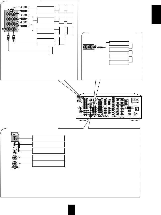
■ PRE OUT connections
Power amplifier
Front speakers
Power amplifier
Surround speakers
Power amplifier
Surround back speakers
Power amplifier
Front center speaker
Powered subwoofer
•Use these jacks when adding additional amplifiers.
•Connect the PRE OUT jacks to the powered speakers or to the power amplifiers respectively.
•To emphasize the deep bass sounds, connect a powered subwoofer.
•Only when enjoying 6.1 or 7.1 channel surround playback, make the surround back connections between the audio equipment.
■ CONNECTING DIGITAL INs and OUT
■ CONNECTING SYSTEM CONTROL
Sherwood component with DIGI LINK II or III
CD player
System
Tape deck control cord
Graphic equalizer
DVD player
•Connect this jack to the DIGI LINK jack of the external Sherwood component that uses the DIGI LINK II or III remote control system.
Component(such as an MD recorder,
CD recorder) with OPTICAL DIGIAL IN
Component with
OPTICAL DIGITAL OUT
Component with
OPTICAL DIGITAL OUT
Component with
COAXIAL DIGITAL OUT
Component with
COAXIAL DIGITAL OUT
•The COAXIAL or the OPTICAL DIGITAL OUTs of the components that are connected to CD, TAPE MONITOR and VIDEO 1 - VIDEO 4 of this unit can be connected to these DIGITAL INs.
•After making digital connections, be sure to match the DIGITAL INs to the corresponding input source respectively. (For details, refer to "When selecting the DIGITAL IN SETUP" on page 37.)
•A digital input should be connected to the components such as LD player, CD player or DVD player, etc. capable of outputting DTS, Dolby Digital or PCM format digital signals,etc.
•If the component with OPTICAL IN jack is connected to the OPTICAL OUT jack of this unit, you can record the high quality sound of CDs etc. without degradation.
•For details, refer to the operating instructions of the connected component.
•When making the COAXIAL DIGITAL connection, be sure to use a 75 Ω COAXIAL cord, not a conventional AUDIO cord.
•All of the commercially available optical fiber cords cannot be used for the equipment. If you have a question about the suitability of a particular cord, please consult your dealer or nearest service organization.
ENGLISH
7
ENGLISH
■ ROOM 2 connections
Another room
Monitor TV
VIDEO IN
VIDEO |
Speakers |
|
IN |
||
|
|
A/V receiver |
AUDIO IN |
or amplifier |
|
|
• If another A/V receiver or integrated amplifier, etc. is connected to these jacks, you can play a different program source in another room as well as one source in the main room at the same time.(For details, refer to "ROOM 2 SOURCE PLAYBACK" on page 31).
• When the multiroom adaptor is connected to control this unit in another room, the ROOM 2 function is more convenient.
 Note:
Note:
• To minimize hum or noise, use high quality connection cords in such a way that there is no humming or noise.
■ CONNECTING MULTI-ROOM
SYSTEM KIT
Another room
OUT |
Adaptor |
IR receiver |
Remote control unit |
|
|
|
|
|
|
|
|
|
|
(Multi-room system kit) |
(Multi room system kit) |
|
|
|
|
|
|
|
|
|
||
|
|
|
|
|
|
|
|
|
|
|
|
|
•To control this unit from a remote location, connect this jack to the output of the multi-room adaptor.
For information on the multi-room system kit, contact the
Xantech corporation at 1-800-843-5465 or www.xantech.com.
■ CONNECTING SPEAKERS
■ SWITCHED AC OUTLETS
Front right |
Front left |
• These outlets are switched on(power-on mode) and off(standby mode) according to the power control as follows(Maximum
Front total capacity is 1A, 100W):
center
Standby mode – switched AC outlet off
Power-on mode – switched AC outlet on
Surround
right
Surround left
Surround back |
Surround back |
right |
left |
•Never short circuit the + and - speaker wires.
•Be sure to connect speakers firmly and correctly according to the channel (left and right ) and the polarity ( + and -).
•Be sure to use speakers with the impedance of over 6 Ω.
•Only when enjoying either 6.1 or 7.1 channel surround playback, connect the surround back left speaker only or both of surround
back speakers.  Note:
Note:
•After installing the speakers, first set the connected speakers to the desired before operating this receiver.(For details, refer to "SETTING THE SPEAKER SETUP" on page 34.)
■ AC INLET
Plug the supplied AC input cord into this AC INLET and then into the wall AC outlet.
To a wall AC outlet.
•Do not use an AC input cord other than the one supplied with this unit. The AC input cord supplied is designed for use with this unit and should not be used with any other device.
8

Front Panel Controls
TUNING/PRESET MODE BUTTON MULTI ROOM |
|
|
BAND BUTTON |
REMOTE SENSOR |
|
|
|
|
TUNING/PRESET UP/DOWN |
SOURCE DIRECT BUTTON |
CINEMA EQ BUTTON |
|
|
|
( / ) BUTTONS |
ROOM 2 BUTTON |
DYNAMIC RANGE BUTTON |
|
||
|
|
MASTER VOLUME |
MULTI CONTROL KNOB |
|
CONTROL KNOB |
|
|
|
|
|
|
|
|
|
E |
X |
T E N D E D |
|
|
|
W R A S |
|
AUDIO/VIDEO SURROUND RECEIVER R-863 |
|
|
|
|
|
|
|
|
|
|
|
|||
|
|
|
|
|
|
|
|
|
|
|
|
|
|||
MULTI CONTROL |
|
|
|
|
|
|
|
|
|
|
|
|
|
MASTER VOLUME |
|
|
BAND |
T/P MODE |
|
|
|
|
|
|
|
|
SOURCE |
CINEMA EQ |
|
|
|
|
|
|
|
|
|
|
|
|
DIRECT |
|
|
|
|||
|
|
MULTI ROOM |
|
|
|
|
|
|
|
|
|
|
|
|
|
|
|
REMOTE SENSOR |
|
|
|
|
|
|
|
|
|
|
|
|
|
|
|
|
|
LOCK |
|
|
|
|
|
|
|
|
|
|
|
|
TUNING/PRESET |
|
|
|
|
|
|
|
|
ROOM2 FEED |
DYNAMIC |
|
|
|
|
|
|
|
|
|
|
|
|
|
|
|
RANGE |
|
|
|
|
|
POWER |
|
|
INPUT SELECTOR |
|
SURROUND MODE |
|
|
|
|
|
||||
|
|
STANDBY |
AUDIO |
VIDEO |
TAPE MON. |
7.1CH DIRECT |
DECODING |
EXTRA SURR. |
|
STEREO DIGITAL/ANALOG |
|
|
|
||
|
|
|
|
|
|
|
|
|
|
|
|
|
|
||
|
|
ON/STANDBY |
|
|
|
|
|
|
|
|
|
|
|
|
|
|
|
|
|
|
|
|
|
|
6.1/7.1 |
|
|
|
|
|
|
|
ON / |
OFF |
|
|
|
|
|
|
|
|
|
|
|
|
|
PHONES |
CHANNEL |
|
|
|
|
|
|
|
|
|
|
|
|
|
|
SPEAKER |
TEST TONE |
TONE MODE |
VIDEO LABEL |
MEMO/ENTER |
|
|
|
|
|
|
|
|
|
||
SELECTOR |
|
|
|
|
|
|
|
|
|
||||||
ON/OFF |
|
|
|
|
|
|
|
|
|
|
|
|
|
|
|
|
|
|
|
|
|
|
|
|
|
|
|
OPTICAL IN |
S-VIDEO |
VIDEO |
L - AUDIO - R |
|
|
|
DIGITAL/ANALOG BUTTON |
|
HEADPHONE JACK |
|
STEREO BUTTON |
||
SPEAKER BUTTON |
EXTRA SURROUND 6.1/7.1 BUTTON |
|||
|
|
|||
POWER SWITCH |
DECODING MODE BUTTON |
|||
7.1 CH DIRECT BUTTON |
||||
|
|
|||
CHANNEL SELECTOR BUTTON |
TAPE MONITOR BUTTON |
|||
|
|
|||
TEST TONE BUTTON |
MEMORY/ENTER BUTTON |
|||
STANDBY BUTTON/INDICATOR |
VIDEO SELECTOR BUTTON |
|||
|
|
|||
TONE MODE BUTTON |
VIDEO LABEL BUTTON |
|||
AUDIO SELECTOR BUTTON |
||||
|
|
|||
|
|
|
|
|
■ FLUORESCENT DISPLAY |
■ VIDEO 4 INPUT JACKS |
|||
VIDEO INPUT INDICATORS |
TUNED INDICATOR |
|||||||||||||
|
ROOM 2 INDICATOR |
|
STEREO INDICATOR |
|||||||||||
|
|
|
|
LOCK INDICATOR |
|
|
|
SOURCE DIRECT INDICATOR |
||||||
|
|
|
|
|
|
|
|
|
|
|
|
|||
|
|
|
|
|
SURROUND MODE |
|
|
AUTO TUNING INDICATOR |
||||||
|
|
|
|
|
|
|
|
MEMORY INDICATOR |
||||||
|
|
|
|
|
INDICATORS |
|
|
|
|
|||||
|
|
|
|
|
|
TAPE MONITOR |
|
|
|
|
PRESET INDICATOR |
|||
|
|
|
|
|
|
INDICATOR |
|
|
|
|
|
CHANNEL |
||
|
|
|
|
|
|
|
|
|
|
|
|
|
INDICATORS |
|
|
|
|
|
|
|
|
|
|||||||
|
|
|
|
|
|
|
|
|
|
|
|
|
|
|
|
|
|
|
|
|
|
|
|
|
|
|
|
|
|
|
|
|
|
|
|
|
|
|
|
|
|
|
|
|


 LOCK
LOCK
|
|
|
|
|
|
|
|
|
|
|
|
|
|
|
|
|
|
|
|
|
|
|
|
|
|
|
|
|
|
|
|
|
|
|
|
|
|
|
|
|
|
|
|
INPUT SIGNAL |
SPEAKER INDICATOR |
|
|
|
|
|||||
INDICATORS |
SLEEP INDICATOR |
|
||||||||
AUTO INDICATOR |
MUTE INDICATOR |
|||||||||
|
|
|
|
|
|
|
|
|
|
|
INPUT, FREQUENCY, VOLUME LEVEL, OPERATING INFORMATIONs, etc.
OPTICAL IN S-VIDEO VIDEO L - AUDIO - R
|
Additional video component |
|
OPTICAL OUT |
|
AUDIO OUT |
S-VIDEO OUT |
|
VIDEO OUT |
|
|
|
• The VIDEO 4 input jacks may be also connected to an additional video component such as a camcorder, a video deck or a video game player, etc.
Use the S-VIDEO jack to make connection to video component with the S-VIDEO OUT jack.
•A signal input into the normal(composite) VIDEO jack will be output in the normal(composite) VIDEO OUT jacks and a signal input into the S-VIDEO jack will be output in the S-VIDEO OUT jacks.
•The OPTICAL DIGITAL OUTs of the component that are connected to CD, TAPE MONITOR and VIDEO 1~VIDEO 4 of this unit can be connected to this OPTICAL IN.
•After making digital connections, be sure to match the DIGITAL INs to the corresponding input source respectively.(For details, refer to "When selecting the DIGITAL IN SETUP" on page 37.)
•This OPTICAL IN should be connected to the component capable of DTS, Dolby Digital or PCM format digital signals, etc.
ENGLISH
9
ENGLISH
Universal Remote Controls
Note: For enhanced Universal Remote Programming instructions and manufacturer’s codes, please refer to the operating manual inclosed with this Universal Remote Control.
This remote control has 3 operating modes as follows:
• OSD (On-Screen Display) mode: Allows you to look at information about basic operation of this unit on your monitor TV and to operate this unit by moving an arrow that appears on the screen of your monitor TV.
• Sherwood mode: Allows you to operate this unit and other Sherwood components like cassette decks, CD players, etc.(To operate other Sherwood components, you should make the DIGI LINK connections between them.)
•Non-Sherwood mode: Allows you to operate other non-Sherwood audio and video components that are remote compatible. Notes:
•The setup code for each component must be entered before operation.
•For setup codes(manufacturer’s codes), please refer to “Set-Up Code Tables” in the operating manual of this remote control.
•Some operation buttons have different functions according to each operation mode.
•Be sure to set the remote control to the correct mode before operation.
DIGI LINK SYSTEM REMOTE CONTROLS
•This section explains the basic functions for Sherwood or OSD mode. For the non-Sherwood mode, refer to the operating manual of this remote control.
•All Sherwood components bearing the DIGI LINK (II or III) logo can be used with this remote control.
•For system remote control operation, first make the DIGI LINK connections between Sherwood components.
•The numbered buttons on the remote control have different functions in different modes. For details, refer to the “FUNCTION TABLE of the NUMBERED BUTTONS” on the following page.
•In the DIGI LINK III remote control system, if pressing PLAY, etc. on CD player or tape deck, CD or TAPE MONITOR is selected automatically on the receiver without selecting the input source. Then PLAY, etc. starts.
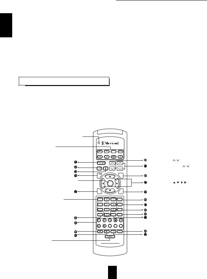
LED LAMP 
DEVICE BUTTONS 
To operate the desired component with this remote
DVD
control, first select the corresponding DEVICE button.
POWER BUTTON |
|
VOLUME UP/DOWN( / ) BUTTONS |
|
CHANNEL LEVEL UP/DOWN( / ) BUTTONS |
|
VOL. |
CH LEVEL |
|
OSD |
CH SEL |
|
ENTER BUTTON 
NUMERIC(1~0) BUTTONS 

•For selecting preset stations in tuner mode.
•For selecting a track or a disc in CD mode, etc.
•When selecting a disc, select disc No. (1~5) within 2 sec. after pressing DISC(marked "P.SCAN") button.
ENTER |
CURSOR CONTROL( |
, |
, |
, |
) BUTTONS |
RPT |
INTRO |
|
|
|
|
A |
B |
|
|
|
|
TITLE |
|
|
7.1 SURR |
|
RETURN |
|
|
AUTO |
|
|
DSP |
|
|
MODE |
|
|
ST |
DISC |
TEST |
CENTER |
P.SCAN |
TONE |
MODE |
TUNER |
CD T1/MON |
AUX |
PHONO |
|
VID1 |
VID2 |
VID3 |
VID4 |
VID5 |
SYS DISP |
SLEEP |
DIRECT IN |
ROOM2 |
|
LIGHT BUTTON 
Activates the backlighting of the remote control |
HOME THEATER MASTER |
RNC-220 |
|
for 7 sec. If any other button is pressed while |
|
the backlighting is on, the remote control will |
|
remain backlit for an additional 7 sec. |
|
10

FUNCTION TABLE of the NUMBERED BUTTONS. |
|
|
|
|
||||||||
Component |
|
|
|
|
|
|
|
|
|
(for DVD player) |
|
|
buttons to be |
|
|
|
|
|
|
|
|
|
|
|
|
|
|
|
|
|
|
|
|
|
|
|
|
|
controlled |
(for receiver, |
|
(for CD player, |
(for tape deck, |
V-756, etc. |
VD-4103, etc. |
VD-2103, etc. |
VD-4106, etc. |
||||
Button |
|
|||||||||||
|
"001") |
|
"001") |
|
"001") |
|
("001") |
("112") |
("114") |
("057") |
("074") |
|
symbol |
|
|
|
|
||||||||
|
|
|
|
|
|
|
|
|
|
|||
|
|
POWER |
|
<POWER> |
|
<POWER> |
|
POWER |
- |
POWER |
POWER |
POWER |
|
|
MUTE |
|
<MUTE> |
|
<MUTE> |
|
ZOOM |
MUTE |
MUTE |
- |
FORWARD SLOW |
|
|
- |
|
- |
|
- |
|
OPEN/CLOSE |
OPEN/CLOSE |
OPEN/CLOSE |
RANDOM |
SELECT/ENTER |
|
CH LEVEL UP( |
) |
<CH LEVEL UP( |
)> |
<CH LEVEL UP( |
)> |
SEARCH |
PAL/NTSC |
KEY UP |
- |
FORWARD SKIP |
|
|
CH LEVEL DOWN( |
) |
<CH LEVEL DOWN( |
)> <CH LEVEL DOWN( |
)> |
(SUBTITLE ON/OFF) |
- |
KEY DOWN |
- |
REVERSE SKIP |
||
|
ON-SCREEN DISPLAY <ON-SCREEN DISPLAY> <ON-SCREEN DISPLAY> |
MENU |
MENU |
MENU |
DISPLAY |
TITLE |
||||||
|
CHANNEL SELECTOR <CHANNEL SELECTOR> <CHANNEL SELECTOR> |
SETUP |
SETUP |
SETUP |
MENU |
MENU |
||||||
|
7.1 CH SURROUND |
REPEAT A< >B |
DECK SELECTOR A |
TITLE |
TITLE |
TITLE |
CLEAR |
RETURN |
||||
|
|
RETURN |
|
INTRO SCAN |
|
DECK SELECTOR B |
RETURN |
RETURN |
RETURN |
RETURN |
OPEN/CLOSE |
|
|
PRESET SCAN |
DISC |
|
- |
|
(DISC) |
+10 |
+10 |
- |
- |
||
|
AUTO/MANUAL |
<AUTO/MANUAL> |
<AUTO/MANUAL> |
AUDIO |
CHANNEL |
NTSC/PAL |
PROGRAM |
RESUME |
||||
|
|
DSP MODE |
|
<DSP MODE> |
<DSP MODE> |
SUBTITLE |
SUBTITLE |
SUBTITLE |
- |
DISPLAY |
||
|
|
STEREO |
|
<STEREO> |
|
<STEREO> |
|
ANGLE |
ANGLE |
AUDIO |
REPEAT |
SUBTITLE |
|
|
- |
|
- |
|
- |
|
PROGRAM |
PROGRAM |
PROGRAM |
SETUP |
- |
TEST |
|
TEST TONE |
|
<TEST TONE> |
<TEST TONE> |
CLEAR |
V-MODE |
L/R/ST |
SELECT/ENTER |
SETUP |
||
|
|
|
||||||||||
|
I |
TUNER |
|
- |
|
REVERSE PLAY |
TIME |
A-TIME |
SLOW |
CURSOR UP |
AUDIO |
|
|
N |
CD |
|
PLAY |
|
FORWARD PLAY |
PLAY |
STEP |
STEP |
CURSOR DOWN |
ANGLE |
|
|
P |
|
|
|||||||||
|
U |
TAPE MONITOR |
PAUSE |
|
PAUSE |
|
PAUSE |
PAUSE |
PAUSE |
TITLE |
CLEAR |
|
|
T |
|
|
|||||||||
|
|
|
|
|
|
|
|
|
|
|
|
|
|
S |
AUX |
|
STOP |
|
STOP |
|
STOP |
STOP |
STOP |
CURSOR LEFT |
REPEAT |
|
|
|
|
|
|
|
|
|
|
|
|
|
|
E |
VIDEO 1 |
|
REVERSE SKIP |
REWIND |
|
REVERSE SEARCH |
REVERSE SEARCH |
REVERSE SEARCH |
- |
RANDOM |
|
|
L |
|
|
|||||||||
|
|
|
|
|
|
|
|
|
|
|
|
|
|
E |
VIDEO 2 |
|
FORWARD SKIP |
FAST FORWARD |
FORWARD SEARCH |
FORWARD SEARCH |
FORWARD SEARCH |
ANGEL |
PROGRAM |
||
|
C |
|
|
|
|
|
|
|
|
|
|
|
|
T |
VIDEO 3 |
|
- |
|
- |
|
REVERSE SKIP |
REVERSE SKIP |
REVERSE SKIP |
AUDIO |
- |
|
O |
|
|
|
|
- |
|
FORWARD SKIP |
FORWARD SKIP |
FORWARD SKIP |
- |
- |
|
R |
VIDEO 4 |
|
- |
|
|
||||||
|
|
- |
|
- |
|
RECORD |
|
REPEAT |
REPEAT |
REPEAT |
CURSOR RIGHT |
REPEAT A<>B |
|
|
- |
|
- |
|
- |
|
REPEAT A<>B |
REPEAT A<>B |
REPEAT A<>B |
- |
- |
|
SYSTEM DISPALY |
<SYSTEM DISPALY> <SYSTEM DISPALY> |
DISPLAY |
ON-SCREEN DISPLAY |
DISPLAY |
- |
- |
|||||
|
|
SLEEP |
|
<SLEEP> |
|
<SLEEP> |
|
MARKER |
MARKER |
SEARCH |
SUBTITLE |
- |
|
|
ROOM 2 |
|
<ROOM 2> |
|
<ROOM 2> |
|
RANDOM |
MEMORY |
PBC |
- |
- |
|
7.1 CH DIRECT |
<7.1 CH DIRECT> |
<7.1 CH DIRECT> |
INTRO SCAN |
INTRO SCAN |
RESUME |
REPEAT A<>B |
- |
||||
|
CURSOR UP( ) |
<CURSOR UP( )> |
<CURSOR UP( )> |
CURSOR UP |
CURSOR UP |
CURSOR UP |
- |
PAUSE |
||||
|
CURSOR DOWN( |
) |
<CURSOR DOWN( )> <CURSOR DOWN( )> |
CURSOR DOWN |
CURSOR DOWN |
CURSOR DOWN |
- |
STOP |
||||
|
CURSOR RIGHT( |
) |
<CURSOR RIGHT( |
)> <CURSOR RIGHT( |
)> |
CURSOR RIGHT |
CURSOR RIGHT |
CURSOR RIGHT |
- |
FORWARD SCAN |
||
|
CURSOR LEFT( |
) |
<CURSOR LEFT( |
)> |
<CURSOR LEFT( |
)> |
CURSOR LEFT |
CURSOR LEFT |
CURSOR LEFT |
- |
REVERSE SCAN |
|
|
|
ENTER |
|
<ENTER> |
|
<ENTER> |
|
ENTER |
ENTER/PLAY |
ENTER/PLAY |
- |
PLAY |
|
VOLUME UP( ) |
|
<VOLUME UP( )> |
<VOLUME UP( )> |
- |
VOLUME UP |
VOLUME UP |
- |
- |
|||
|
VOLUME DOWN( |
) |
<VOLUME DOWN( )> <VOLUME DOWN( )> |
- |
VOLUME DOWN |
VOLUME DOWN |
- |
- |
||||
|
|
0~9 |
|
- |
|
- |
|
0~9 |
0/10~9 |
0/10~9 |
0~9 |
0~9 |
Notes:
•Some functions for CD player, tape deck, etc. may not be available.
•For details about functions, refer to the operating instructions of each component.
•The functions in < > work for this receiver, not for the CD player or tape deck.
ENGLISH
11
ENGLISH
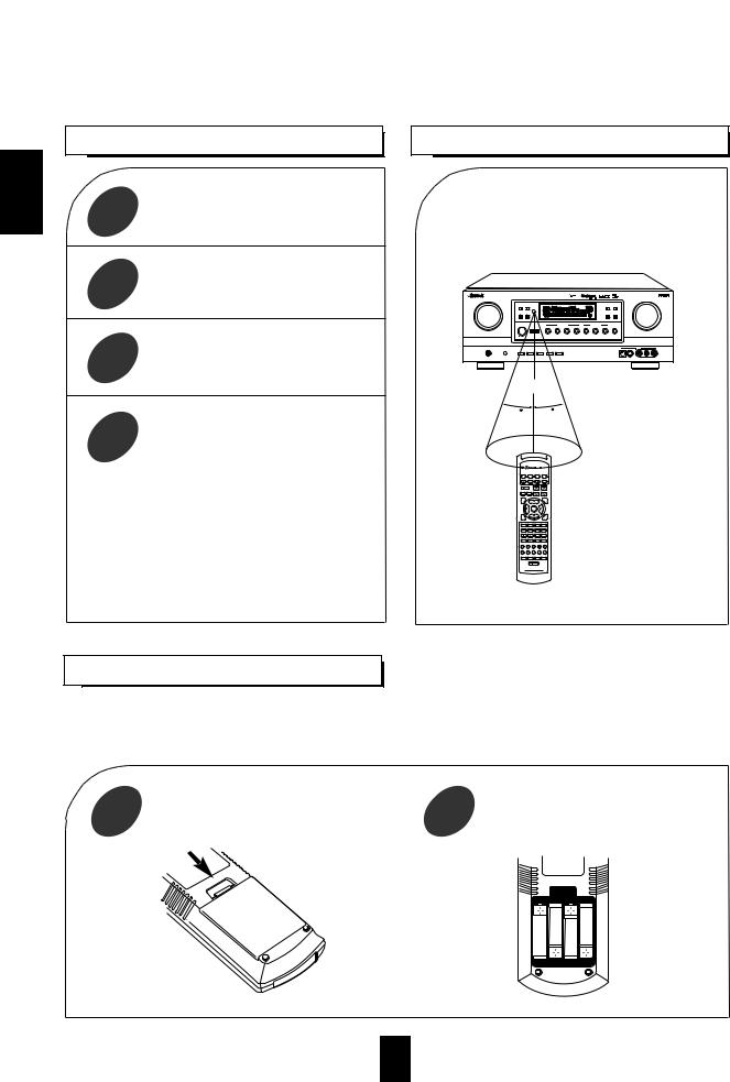
OPERATING COMPONENTS WITH REMOTE CONTROL
setup code of the components 1 referring to “ENTERING A
CODE”(page14).
you want to
2
button on the remote 3 to the component
.
Press the button corresponding to the 4 operation you want while aiming the
remote control at the REMOTE SENSOR on the component.
•When a button is pressed, the corresponding DEVICE button flickers.
•When operating a Sherwood CD player or tape deck using the system remote control, aim the remote control at the REMOTE SENSOR on this unit.
•However, in case of Sherwood DVD player, aim it at the REMOTE SENSOR on the corresponding component.
REMOTE CONTROL OPERATION RANGE
•Use the remote control within a range of about 7 meters (23 feet) and angles of up to 30 degrees aiming at the remote sensor.
R-863 |
W R A S |
7m
30 |
30 |
VOL. CH LEVEL
HOME THEATER MASTER
RNC-220
BATTERIES
When this remote control does not operate the component, the old batteries should be replaced.
If the batteries are removed for a longer period of time, the remote control might lose its memory and require reprogramming
1 |
Remove the cover. |
2 |
Load four batteries(“AAA” size, 1.5 V) |
||||||||||||||||||||
|
matching the polarity. |
||||||||||||||||||||||
|
|
|
|
|
|
|
|
|
|
|
|
|
|
|
|
|
|
|
|
|
|
|
|
|
|
|
|
|
|
|
|
|
|
|
|
|
|
|
|
|
|
|
|
|
|
|
|
|
|
|
|
|
|
|
|
|
|
|
|
|
|
|
|
|
|
|
|
|
|
|
|
|
|
|
|
|
|
|
|
|
|
|
|
|
|
|
|
|
|
|
|
|
|
|
|
12

ADDITIONAL INFORMATION ON REMOTE COMMAND CODES
• This receiver recognizes and responds to IR codes that are not transmitted by the supplied remote control unit. |
ENGLISH |
|||||
|
||||||
These commands and their corresponding functions, shown on the following table, are made available for |
|
|||||
custom installers and advanced hobbysts who are already familiar with the programming of such devices as the |
|
|||||
Crestron Touch Screen and the Philps Pronto. |
|
|
|
|
||
Custom Code : 8345H(NEC) |
|
|
|
|
|
|
|
|
|
|
|
|
|
|
|
|
|
|
|
|
FUNCTIONS |
CODES |
|
FUNCTIONS |
CODES |
|
|
|
|
|
|
|
|
|
DTS |
70H |
|
DSP MODE |
5CH |
|
|
|
|
|
|
|
|
|
Dolby Digital |
71H |
|
VIDEO 1 |
56H |
|
|
|
|
|
|
|
|
|
EXTRA SURROUND 6.1/7.1 |
44H |
|
VIDEO 2 |
5AH |
|
|
|
|
|
|
|
|
|
DECODING MODE |
58H |
|
VIDEO 3 |
07H |
|
|
|
|
|
|
|
|
|
STEREO |
4FH |
|
VIDEO 4 |
5BH |
|
|
|
|
|
|
|
|
|
DIGITAL/ANALOG |
E1H |
|
TUNER |
03H |
|
|
|
|
|
|
|
|
|
Dolby Pro Logic II Movie |
E8H |
|
TAPE MONITOR |
06H |
|
|
|
|
|
|
|
|
|
Dolby Pro Logic II Music |
E9H |
|
AUX |
0AH |
|
|
|
|
|
|
|
|
|
DTS Neo Movie |
EDH |
|
CD |
0BH |
|
|
|
|
|
|
|
|
|
DTS Neo Music |
EEH |
|
7.1 CH DIRECT |
4AH |
|
|
|
|
|
|
|
|
|
MPEG |
EBH |
|
SOURCE DIRECT |
7BH |
|
|
|
|
|
|
|
|
|
PCM |
EFH |
|
|
|
|
|
|
|
|
|
|
|
|
13
|
|
|
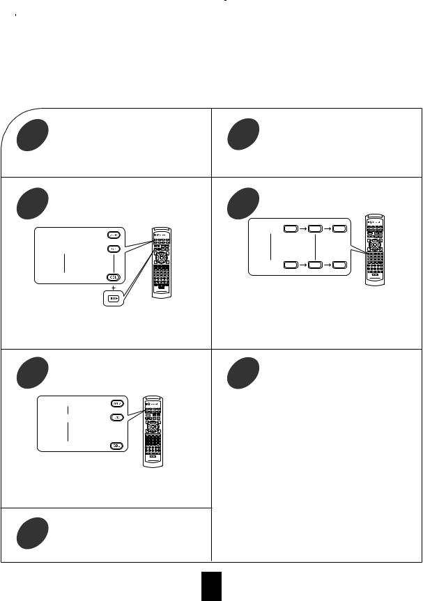
ENTERING A SETUP CODE |
|
|
|
|
|
|
ENGLISH |
|
|
|
|
|
• Because only the setup codes for CD player and DVD player among Sherwood components are listed in the operating manual of this |
|||
|
|
• This remote control can control up to eight different components. |
||
|
|
• Before operating audio and video components using the remote control supplied with this receiver, the setup code for each |
||
|
|
component should be entered. |
||
|
|
remote control, when entering a setup code for Sherwood components for system remote control operation, find the corresponding setup |
||
|
|
code in the “FUNCTION TABLE of the NUMBERED BUTTONS” on page 11 in this operating instructions. For your reference, the setup |
||
|
|
cord for each Sherwood component such as CD player, tape deck and DVD player(V-756, etc.) is “001” respectively.(However, the setup |
||
|
|
code for some Sherwood DVD player such as VD-4103, etc. is “057”, “074”, “112”, “114”.) Enter each setup code for CD player and tape |
||
|
|
deck doing steps , and as follows. |
||
1 |
|
|
2 |
|
|
|
|
|
Example) When entering the setup code for this |
Example) The correct setup code for this receiver is |
|||||||
|
receiver, turn on this receiver. |
|
“001”. |
|
|
|
|
|
3 |
|
and the |
4 |
|
|
|
|
control |
|
|
|
|
|
|
|
||
|
For receiver or amplifier : |
For |
"001" : |
0 |
0 |
1 |
|
|
|
|
|
|
|
|
|
||
|
For CD player |
: |
|
|
|
|
|
|
|
|
|
For |
"102" : |
1 |
0 |
2 |
|
|
For CABLE |
: |
|
|
|
|
|
|
|
|
|
Your component will be turned off when the correct |
|||||
|
|
|
setup code is entered. |
|
|
|||
Then the LED lamp and the corresponding DEVICE |
Continue to enter the corresponding codes until your |
|||||||
component turns off. |
|
|
||||||
button on the remote control light up for 20 seconds. |
If the LED lamp and the corresponding DEVICE |
|||||||
|
|
|
button go off, start from the step again. |
|
||||
5 |
Press the corresponding DEVICE button to |
6 |
|
|
|
using the |
|
|
store the setup code. |
|
|
|
buttons on the remote |
||||
|
|
|
|
|
CH |
and |
||
|
|
|
|
|
|
|
||
|
receiver or amplifier : |
If any of the buttons do not perform as they should |
||||||
|
CD player |
: |
start from step |
|
again to enter the next setup code. |
|||
|
Note: |
|
|
|
|
|
||
|
|
|
|
|
|
|
|
|
|
|
|
Some audio and video components have separate |
|||||
|
|
|
buttons for POWER ON/OFF. |
|
|
|||
|
CABLE |
: |
In this case, press the corresponding DEVICE button |
|||||
|
|
|
to turn the component ON and press the POWER |
|||||
|
|
|
button to turn the component OFF. |
|
||||
|
|
|
If there is no correct setup code or if the |
|
||||
|
LED lamp and the corresponding DEVICE |
Manufacturer/Brand for your component is not listed |
||||||
|
flicker twice. |
in “Set-Up Code Table” in the operating manual of |
||||||
|
|
|
this remote control, please use the “Auto Search |
|||||
|
|
|
Method” on page 10 in the operating manual of this |
|||||
7 |
|
to for each |
remote control. |
|
|
|
|
|
|
Although each setup code is designed to work with |
|||||||
|
|
|||||||
|
|
many different modes, certain codes may not work with |
||||||
|
|
some models. (Also, certain codes may only operate |
||||||
|
|
|
some of the functions available on a given model.) |
|||||
14
Operations
Notes :
Before operating this receiver with the supplied remote control, refer to “Universal Remote Controls” on page 10 for details about operation. Before operating this receiver, first set this unit as desired for optimum performance, by using the OSD menu setting procedures. (For details, refer to “OSD Menu Settings” on page 32.)
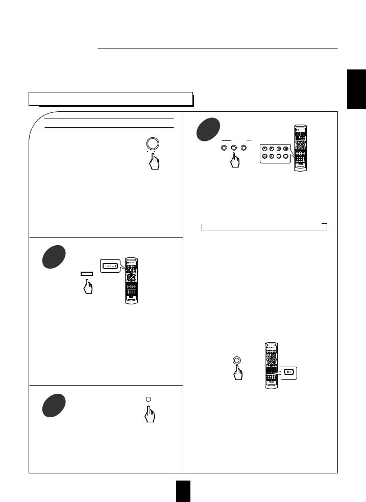
LISTENING TO A PROGRAM SOURCE
Before operation
Enter the standby mode. |
POWER |
|
ON / OFF |
The STANDBY button lights up in red.
This means that the receiver is not disconnected from the AC mains and a small amount of current is retained to support the memorized contents and operation readiness.
To switch the power off, push the POWER switch again.
Then power is cut off and the STANDBY button goes off.
1
STANDBY
ON/STANDBY
or
Each time the STANDBY button on the front panel or the POWER button on the remote control is pressed, the receiver is turned on to enter the operating mode(the STANDBY button lights up in blue) or off to enter the standby mode (the STANDBY button lights up in red).
In the standby mode, if one of the INPUT SELECTOR buttons is pressed, the receiver is turned on automatically and the desired input is selected.
SPEAKER
2 |
ON/OFF |
Then the SPEAKER indicator lights up on the display and sound can be heard from the speakers connected to the speaker terminals.
When using headphones for private listening, press the SPEAKER button again to switch the speakers off.
3
INPUT SELECTOR
AUDIO VIDEO TAPE MON.
TUNER |
CD |
T1/MON |
AUX |
or |
|
|
|
VID1 |
VID2 |
VID3 |
VID4 |
Each time the “AUDIO” button is pressed, the input source changes as follows:
|
TUNER |
CD |
AUX |
|
|
|
|||
|
(frequency display) |
|
|
|
|
|
|
|
|
Each time the “VIDEO” button is pressed, the input source changes as follows:
VIDEO 1 VIDEO 2 VIDEO 3 VIDEO 4
When the TAPE MONITOR button is set to on so that “TAPE MON” lights up, other inputs can not be heard from the speakers.
To listen to an input source except TAPE MONITOR, be sure to set the TAPE MONITOR button to off.
TAPE MONITOR function
You can connect either a tape deck or a graphic equalizer to the receiver’s TAPE MONITOR jacks.
Only when you listen to the component connected to these jacks, set the TAPE MONITOR button to on.
If you connect a 3-head tape deck, you can listen to the sound being recorded during recording, and not the source sound. For further details, refer to the operating instructions of the connected component.
When selecting the 7.1 CH DIRECT as desired
7.1CH DIRECT
or
DIRECT IN
Depending on the surround back speaker setting, “7.1(,6.1 or 5.1) CH DIRECT” is displayed and the 8(/7/6) separate analog signals from the component connected to this input pass through the tone, volume and bass management(if selected) circuits only and can be heard from your speakers.(In case that the TAPE MONITOR button is set to on, the TAPE MONITOR button is automatically set to off.)
Press the 7.1 CH DIRECT button or select the desired input source to cancel the 7.1 CH direct function.
These analog signals can be heard only. They cannot be recorded.
ENGLISH
15
 Loading...