


OPERATING INSTRUCTIONS MANUEL D’UTILISATION BEDIENUNGSANLEITUNG
Audio/Video Receiver
R-772(G)2007.9.174:43PM 2
ENGLISH
Introduction
READ THIS BEFORE OPERATING YOUR UNIT
|
|
|
CAUTION |
: TO REDUCE THE RISK OF ELECTRIC |
|
SHOCK, DO NOT REMOVE COVER (OR |
||
|
BACK). NO USER-SERVICEABLE PARTS |
|
|
INSIDE. REFER SERVICING TO |
|
|
QUALIFIED SERVICE PERSONNEL. |
|
|
|
|
This symbol is intended to alert the user to the presence of uninsulated "dangerous voltage" within the product's enclosure that may be of sufficient magnitude to constitute a risk of electric shock to persons.
This symbol is intended to alert the user to the presence of important operating and maintenance (servicing) instructions in the literature accompanying the appliance.
WARNING : TO REDUCE THE RISK OF FIRE OR ELECTRIC SHOCK,
DO NOT EXPOSE THIS APPLIANCE TO RAIN OR MOISTURE.
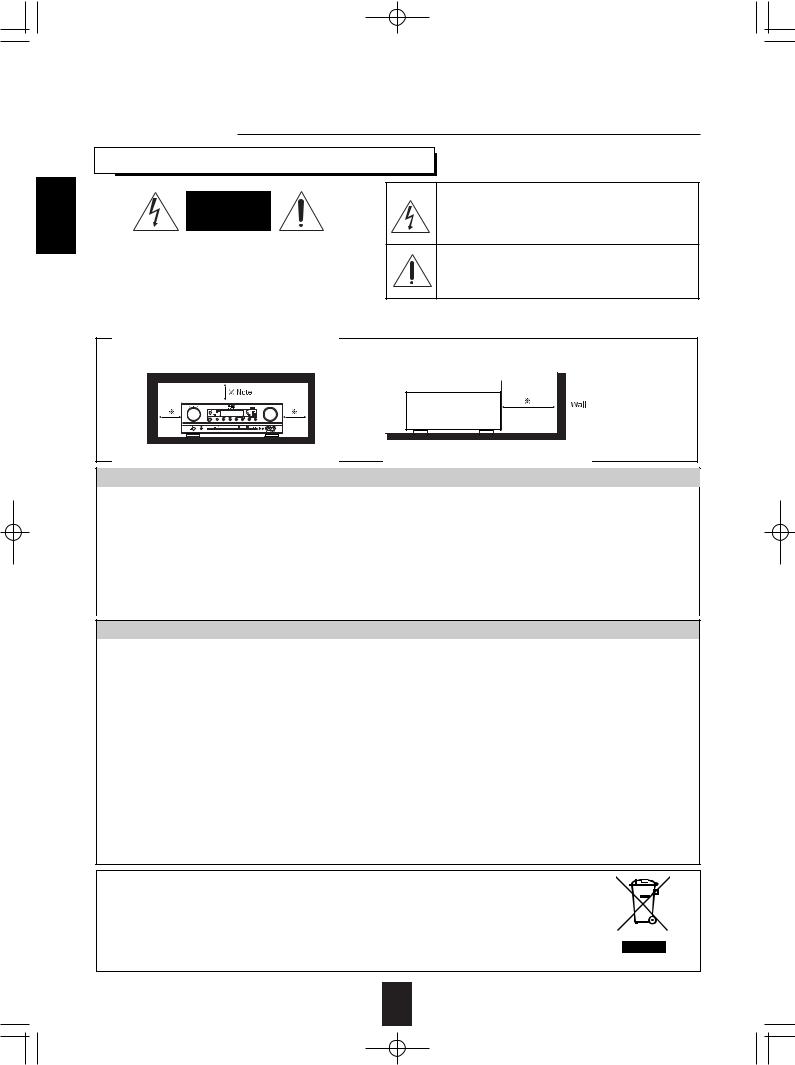
Caution regarding installation
Note : For heat dispersal, do not install this unit in a confined space such as a bookcase or similar enclosure.
Do not block ventilation openings or stack other equipment on the top.
FOR YOUR SAFETY
|
|
|
|
|
|
Units shipped to Australia are designed for operation on 240 V AC only. |
|
|
|
|
|
|
To ensure safe operation, the three-pin plug supplied must be inserted only into a standard three- |
|
|
|
|
|
|
pin power point which is effectively earthed through the normal household wiring. Extension cords |
|
EUROPE |
|
|
220 V |
|
used with the equipment must be three-core and be correctly wired to provide connection to earth. |
|
|
|
|
Improper extension cords are a major cause of fatalities. The fact that the equipment |
||
|
|
|
- |
|
||
|
AUSTRALIA |
|
|
|
operates satisfactorily does not imply that the power point is earthed and that the installation |
|
|
|
|
240 V |
|
||
|
|
|
|
|
is completely safe. For your safety, if in any doubt about the effective earthing of the power |
|
|
|
|
|
|
|
|
|
|
|
|
|
|
point, consult a qualified electrician. |
|
|
|
|
|
|
PAN-EUROPEAN UNIFIED VOLTAGE |
|
|
|
|
|
|
All units are suitable for use on supplies 220-240 V AC. |
CAUTION
•Leave a space around the unit for sufficient ventilation.
•Avoid installation in extremely hot or cold locations, or in an area that is exposed to direct sunlight or heating equipment.
•Keep the unit free from moisture, water, and dust.
•Do not let foreign objects in the unit.
•The ventilation should not be impeded by covering the ventilation openings with items, such as newspapers, table-cloths, curtains, etc.
•No naked flame sources, such as lighted candles, should be placed on the unit.
•Please be care the environmental aspects of battery disposal.
•The unit shall not be exposed to dripping or splashing for use.
•No objects filled with liquids, such as vases, shall be placed on the unit.
•Do not let insecticides, benzene, and thinner come in contact with the set.
•Never disassemble or modify the unit in any way.
■Notes on the AC power cord and the wall outlet.
•The unit is not disconnected from the AC power source(mains) as long as it is connected to the wall outlet, even if the unit has been turned off.
•To completely disconnect this product from the mains, disconnect the plug from the wall socket outlet.
•When setting up this product, make sure that the AC outlet you are using is easily acceptable.
•Disconnect the plug from the wall outlet when not using the unit for long periods of time.
Note on recycling
This product’s packaging materials are recyclable and can be reused. Please dispose of any materials in accordance with the local recycling regulations.
When discarding the unit, comply with local rules or regulations.
Batteries should never be thrown away or incinerated but disposed of in accordance with the local regulations concerning chemical waste.
This product and the accessories packed together constitute the applicable product according to the WEEE directive except batteries.
2
R-772(G)2007.9.174:43PM 3
CONTENTS
• Introduction
READ THIS BEFORE OPERATING YOUR UNIT . . . . . . . . . . . . . . . . . . . . . . . . . . . . . . . 2
• System Connections . . . . . . . . . . . . . . . . . . . . . . . . . . . . . . . . . . . . . . . . . . . . . . . . . . . . . . . . . . 4
• Front Panel Controls . . . . . . . . . . . . . . . . . . . . . . . . . . . . . . . . . . . . . . . . . . . . . . . . . . . . . . . . . 13
• Universal Remote Controls . . . . . . . . . . . . . . . . . . . . . . . . . . . . . . . . . . . . . . . . . . . . . . . . . . . . 15 OPERATING COMPONENTS WITH REMOTE CONTROL . . . . . . . . . . . . . . . . . . . . . . 17 REMOTE CONTROL OPERATION RANGE . . . . . . . . . . . . . . . . . . . . . . . . . . . . . . . . . . 17 LOADING BATTERIES . . . . . . . . . . . . . . . . . . . . . . . . . . . . . . . . . . . . . . . . . . . . . . . . . . 17 USING FUNCTIONS OF REMOTE CONTROL . . . . . . . . . . . . . . . . . . . . . . . . . . . . . . . . 18
• ROOM 2 Remote Controls
REMOTE CONTROL OPERATION RANGE . . . . . . . . . . . . . . . . . . . . . . . . . . . . . . . . . . 21 LOADING BATTERY . . . . . . . . . . . . . . . . . . . . . . . . . . . . . . . . . . . . . . . . . . . . . . . . . . . . 21
• Operations
LISTENING TO A PROGRAM SOURCE . . . . . . . . . . . . . . . . . . . . . . . . . . . . . . . . . . . . . 22 SURROUND SOUND . . . . . . . . . . . . . . . . . . . . . . . . . . . . . . . . . . . . . . . . . . . . . . . . . . . . 24 ENJOYING SURROUND SOUND . . . . . . . . . . . . . . . . . . . . . . . . . . . . . . . . . . . . . . . . . . 26 LISTENING TO RADIO BROADCASTS . . . . . . . . . . . . . . . . . . . . . . . . . . . . . . . . . . . . . 30 LISTENING TO RDS BROADCASTS(FM ONLY) . . . . . . . . . . . . . . . . . . . . . . . . . . . . . . 32 (RDS Tuner(Regional Option for some countries in Europe, etc.))
OTHER FUNCTIONS . . . . . . . . . . . . . . . . . . . . . . . . . . . . . . . . . . . . . . . . . . . . . . . . . . . . 34 ROOM 2 SOURCE PLAYBACK . . . . . . . . . . . . . . . . . . . . . . . . . . . . . . . . . . . . . . . . . . . . 35 RECORDING . . . . . . . . . . . . . . . . . . . . . . . . . . . . . . . . . . . . . . . . . . . . . . . . . . . . . . . . . . 36 DIGITAL AUDIO RECORDING WITH MD RECORDER . . . . . . . . . . . . . . . . . . . . . . . . . 37
• OSD Menu Settings . . . . . . . . . . . . . . . . . . . . . . . . . . . . . . . . . . . . . . . . . . . . . . . . . . . . . . . . . . . 38 SETTING THE SYSTEM SETUP . . . . . . . . . . . . . . . . . . . . . . . . . . . . . . . . . . . . . . . . . . . 40 SETTING THE INPUT SETUP . . . . . . . . . . . . . . . . . . . . . . . . . . . . . . . . . . . . . . . . . . . . . 44 SETTING THE SPEAKER / ROOM EQ SETUP . . . . . . . . . . . . . . . . . . . . . . . . . . . . . . . 48 SETTING THE CH LEVEL SETUP . . . . . . . . . . . . . . . . . . . . . . . . . . . . . . . . . . . . . . . . . 55 SETTING THE SOUND PARAMETER . . . . . . . . . . . . . . . . . . . . . . . . . . . . . . . . . . . . . . 57 SETTING THE MULTI ROOM SETUP . . . . . . . . . . . . . . . . . . . . . . . . . . . . . . . . . . . . . . . 61
• Troubleshooting Guide . . . . . . . . . . . . . . . . . . . . . . . . . . . . . . . . . . . . . . . . . . . . . . . . . . . . . . . 62
• Specifications . . . . . . . . . . . . . . . . . . . . . . . . . . . . . . . . . . . . . . . . . . . . . . . . . . . . . . . . . . . . . . . 63
• Setup Code Table . . . . . . . . . . . . . . . . . . . . . . . . . . . . . . . . . . . . . . . . . . . . . . . . . . . . . . . . . . . . 64
ENGLISH
3
System Connections
|
• Please be certain that this unit is unplugged from the AC outlet before making any connections. |
|
|
• Since different components often have different terminal names, carefully read the operating instructions of the |
|
ENGLISH |
component connected. |
|
• Be sure to observe the color coding when connecting audio, video and speaker cords. |
||
|
• Make connections firmly and correctly. If not, it can cause loss of sound, noise or damage to the receiver.
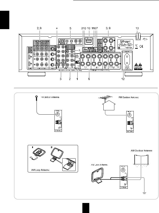
1. CONNECTING ANTENNAS
•Change the position of the FM indoor antenna until you get the best reception of your favorite FM stations.
•Place the AM loop antenna as far as possible from the receiver, TV set, speaker cords and the AC input cord and set it to a direction for the best reception.
•If the reception is poor with the AM loop antenna, an AM outdoor antenna can be used in place of the AM loop antenna.
•A 75Ω outdoor FM antenna may be used to further improve the reception. Disconnect the indoor antenna before replacing it with the outdoor one.
4
R-772(G)2007.9.174:43PM 5
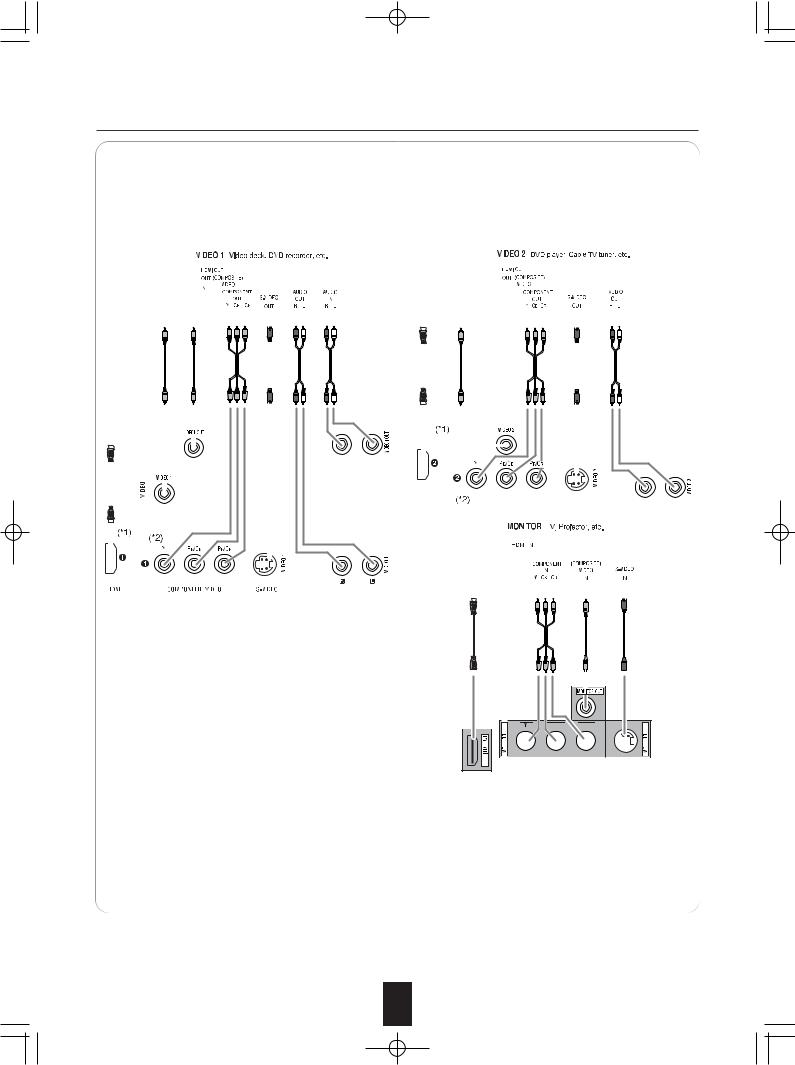
2. CONNECTING VIDEO COMPONENTS
• The jacks of VIDEO 1 may also be connected to a DVD recorder or other digital video recording |
|
|||||||||||||||||||||||||||||||||||||||||||||||||||||||||||||||||
|
component. |
|
||||||||||||||||||||||||||||||||||||||||||||||||||||||||||||||||
|
For details, refer to the operating instructions of the component to be connected. |
ENGLISH |
||||||||||||||||||||||||||||||||||||||||||||||||||||||||||||||||
• The jacks of VIDEO 2/VIDEO 3 can also be connected to an additional video component such as a cable |
||||||||||||||||||||||||||||||||||||||||||||||||||||||||||||||||||
|
||||||||||||||||||||||||||||||||||||||||||||||||||||||||||||||||||
|
TV tuner or satellite system. |
|
||||||||||||||||||||||||||||||||||||||||||||||||||||||||||||||||
• Connect the jacks of VIDEO 3 to the video component in the same way. |
|
|||||||||||||||||||||||||||||||||||||||||||||||||||||||||||||||||
|
|
|
|
|
|
|
|
|
|
|
|
|
|
|
|
|
|
|
|
|
|
|
|
|
|
|
|
|
|
|
|
|
|
|
|
|
|
|
|
|
|
|
|
|
|
|
|
|
|
|
|
|
|
|
|
|
|
|
|
|
|
|
|
|
|
|
|
|
|
|
|
|
|
|
|
|
|
|
|
|
|
|
|
|
|
|
|
|
|
|
|
|
|
|
|
|
|
|
|
|
|
|
|
|
|
|
|
|
|
|
|
|
|
|
|
|
|
|
|
|
|
|
|
|
|
|
|
|
|
|
|
|
|
|
|
|
|
|
|
|
|
|
|
|
|
|
|
|
|
|
|
|
|
|
|
|
|
|
|
|
|
|
|
|
|
|
|
|
|
|
|
|
|
|
|
|
|
|
|
|
|
|
|
|
|
|
|
|
|
|
|
|
|
|
|
|
|
|
|
|
|
|
|
|
|
|
|
|
|
|
|
|
|
|
|
|
|
|
|
|
|
|
|
|
|
|
|
|
|
|
|
|
|
|
|
|
|
|
|
|
|
|
|
|
|
|
|
|
|
|
|
|
|
|
|
|
|
|
|
|
|
|
|
|
|
|
|
|
|
|
|
|
|
|
|
|
|
|
|
|
|
|
|
|
|
|
|
|
|
|
|
|
|
|
|
|
|
|
|
|
|
|
|
|
|
|
|
|
|
|
|
|
|
|
|
|
|
|
|
|
|
|
|
|
|
|
|
|
|
|
|
|
|
|
|
|
|
|
|
|
|
|
|
|
|
|
|
|
|
|
|
|
|
|
|
|
|
|
|
|
|
|
|
|
|
|
|
|
|
|
|
|
|
|
|
|
|
|
|
|
|
|
|
|
|
|
|
|
|
|
|
|
|
|
|
|
|
|
|
|
|
|
|
|
|
|
|
|
|
|
|
|
|
|
|
|
|
|
|
|
|
|
|
|
|
|
|
|
|
|
|
|
|
|
|
|
|
|
|
|
|
|
|
|
|
|
|
|
|
|
|
|
|
|
|
|
|
|
|
|
|
|
|
|
|
|
|
|
|
|
|
|
|
|
|
|
|
|
|
|
|
|
|
|
|
|
|
|
|
|
|
|
|
|
|
|
|
|
|
|
|
|
|
|
|
|
|
|
|
|
|
|
|
|
|
|
|
|
|
|
|
|
|
|
|
|
|
|
|
|
|
|
|
|
|
|
|
|
|
|
|
|
|
|
|
|
|
|
|
|
|
|
|
|
|
|
|
|
|
|
|
|
|
|
|
|
|
|
|
|
|
|
|
|
|
|
|
|
|
|
|
|
|
|
|
|
|
|
|
|
|
|
|
|
|
|
|
|
|
|
|
|
|
|
|
|
|
|
|
|
|
|
|
|
|
|
|
|
|
|
|
|
|
|
|
|
|
|
|
|
|
|
|
|
|
|
|
|
|
|
|
|
|
|
|
|
|
|
|
|
|
|
|
|
|
|
|
|
|
|
|
|
|
|
|
|
|
|
|
|
|
|
|
|
|
|
|
|
|
|
|
|
|
|
|
|
|
|
|
|
|
|
|
|
|
|
|
|
|
|
|
|
|
|
|
|
|
|
|
|
|
|
|
|
|
|
|
|
|
|
|
|
|
|
|
|
|
|
|
|
|
|
|
|
|
|
|
|
|
|
|
|
|
|
|
|
|
|
|
|
|
|
|
|
|
|
|
|
|
|
|
|
|
|
|
|
|
|
|
|
|
|
|
|
|
|
|
|
|
|
|
|
|
|
|
|
|
|
|
|
|
|
|
|
|
|
|
|
|
|
|
|
|
|
|
|
|
|
|
|
|
|
|
|
|
|
|
|
|
|
|
|
|
|
|
|
|
|
|
|
|
|
|
|
|
|
|
|
|
|
|
|
|
|
|
|
|
|
|
|
|
|
|
|
|
|
|
|
|
|
|
|
|
|
|
|
|
|
|
|
|
|
|
|
|
|
|
|
|
|
|
|
|
|
|
|
|
|
|
|
|
|
|
|
|
|
|
|
|
|
|
|
|
|
|
|
|
|
|
|
|
|
|
|
|
|
|
|
|
|
|
|
|
|
|
|
|
|
|
|
|
|
|
|
|
|
|
|
|
|
|
|
|
|
|
|
|
|
|
|
|
|
|
|
|
|
|
|
|
|
|
|
|
|
|
|
|
|
|
|
|
|
|
|
|
|
|
|
|
|
|
|
|
|
|
|
|
|
|
|
|
|
|
|
|
|
|
|
|
|
|
|
|
|
|
|
|
|
|
|
|
|
|
|
|
|
|
|
|
|
|
|
|
|
|
|
|
|
|
|
|
|
|
|
|
|
|
|
|
|
|
|
|
|
|
|
|
|
|
|
|
|
|
|
|
|
|
|
|
|
|
|
|
|
|
|
|
|
|
|
|
|
|
|
|
|
|
|
|
|
|
|
|
|
|
|
|
|
|
|
|
|
|
|
|
|
|
|
|
|
|
|
|
|
|
|
|
|
|
|
|
|
|
|
|
|
|
|
|
|
|
|
|
|
|
|
|
|
|
|
|
|
|
|
|
|
|
|
|
|
|
|
|
|
|
|
|
|
|
|
|
|
|
|
|
|
|
|
|
|
|
|
|
|
|
|
|
|
|
|
|
|
|
|
|
|
|
|
|
|
|
|
|
|
|
|
|
|
|
|
|
|
|
|
|
|
|
|
|
|
|
|
|
|
|
|
|
|
|
|
|
|
|
|
|
|
|
|
|
|
|
|
|
|
|
|
|
|
|
|
|
|
|
|
|
|
|
|
|
|
|
|
|
|
|
|
|
|
|
|
|
|
|
|
|
|
|
|
|
|
|
|
|
|
|
|
|
|
|
|
|
|
|
|
|
|
|
|
|
|
|
|
|
|
|
|
|
|
|
|
|
|
|
|
|
|
|
|
|
|
|
|
|
|
|
|
|
|
|
|
|
|
|
|
|
|
|
|
|
|
|
|
|
|
|
|
|
|
|
|
|
|
|
|
|
|
|
|
|
|
|
|
|
|
|
|
|
|
|
|
|
|
|
|
|
|
|
|
|
|
|
|
|
|
|
|
|
|
|
|
|
|
|
|
|
|
|
|
|
|
|
|
|
|
|
|
|
|
|
|
|
|
|
|
|
|
|
|
|
|
|
|
|
|
|
|
|
|
|
|
|
|
|
|
|
|
|
|
|
|
|
|
|
|
|
|
|
|
|
|
|
|
|
|
|
|
|
|
|
|
|
|
|
|
|
|
|
|
|
|
|
|
|
|
|
|
|
|
|
|
|
|
|
|
|
|
|
|
|
|
|
|
|
|
|
|
|
|
|
|
|
|
|
|
|
|
|
|
|
|
|
|
|
|
|
|
|
|
|
|
|
|
|
|
|
|
|
|
|
|
|
|
|
|
|
|
|
|
|
|
|
|
|
|
|
|
|
|
|
|
|
|
|
|
|
|
|
|
|
|
|
|
|
|
|
|
|
|
|
|
|
|
|
|
|
|
|
|
|
|
|
|
|
|
|
|
|
|
|
|
|
|
|
|
|
|
|
|
|
|
|
|
|
|
|
|
|
|
|
|
|
|
|
|
|
|
|
|
|
|
|
|
|
|
|
|
|
|
|
|
|
|
|
|
|
|
|
|
|
|
|
|
|
|
|
|
|
|
|
|
|
|
|
|
|
|
|
|
|
|
|
|
|
|
|
|
|
|
|
|
|
|
|
|
|
|
|
|
|
|
|
|
|
|
|
|
|
|
|
|
|
|
|
|
|
|
|
|
|
|
|
|
|
|
|
|
|
|
|
|
|
|
|
|
|
|
|
|
|
|
|
|
|
|
|
|
|
|
|
|
|
|
|
|
|
|
|
|
|
|
|
|
|
|
|
|
|
|
|
|
|
|
|
|
|
|
|
|
|
|
|
|
|
|
|
|
|
|
|
|
|
|
|
|
|
|
|
|
|
|
|
|
|
|
|
|
|
|
|
|
|
|
|
|
|
|
|
|
|
|
|
|
|
|
|
|
|
|
|
|
|
|
|
|
|
|
|
|
|
|
|
|
|
|
|
|
|
|
|
|
|
|
|
|
|
|
|
|
|
|
|
|
|
|
|
|
|
|
|
|
|
|
|
|
|
|
|
|
|
|
|
|
|
|
|
|
|
|
|
|
|
|
|
|
|
|
|
|
|
|
|
|
|
|
|
|
|
|
|
|
|
|
|
|
|
|
|
|
|
|
|
|
|
|
|
|
|
|
|
|
|
|
|
|
|
|
|
|
|
|
|
|
|
|
|
|
|
|
|
|
|
|
|
|
|
|
|
|
|
|
|
|
|
|
|
|
|
|
|
|
|
|
|
|
|
|
|
|
|
|
|
|
|
|
|
|
|
|
|
|
|
|
|
|
|
|
|
|
|
|
|
|
|
|
|
|
|
|
|
|
|
|
|
|
|
|
|
|
|
|
|
|
|
|
|
|
|
|
|
|
|
|
|
|
|
|
|
|
|
|
|
|
|
|
|
|
|
|
|
|
|
|
|
|
|
|
|
|
|
|
|
|
|
|
|
|
|
|
|
|
|
|
|
|
|
|
|
|
|
|
|
|
|
|
|
|
|
|
|
|
|
|
|
|
|
|
|
|
|
|
|
|
|
|
|
|
|
|
|
|
|
|
|
|
|
|
|
|
|
|
|
|
|
|
|
|
|
|
|
|
|
|
|
|
|
|
|
|
|
|
|
|
|
|
|
|
|
|
|
|
|
|
|
|
|
|
|
|
|
|
|
|
|
|
|
|
|
|
|
|
|
|
|
|
|
|
|
|
|
|
|
|
|
|
|
|
|
|
|
|
|
|
|
|
|
|
|
|
|
|
|
|
|
|
|
|
|
|
|
|
|
|
|
|
|
|
|
|
|
|
|
|
|
|
|
|
|
|
|
|
|
|
|
|
|
|
|
|
|
|
|
|
|
|
|
|
|
|
|
|
|
|
|
|
|
|
|
|
|
|
|
|
|
|
|
|
|
|
|
|
|
|
|
|
|
|
|
|
|
|
|
|
|
|
|
|
|
|
|
|
|
|
|
|
|
|
|
|
|
|
|
|
|
|
|
|
|
|
|
|
|
|
|
|
|
|
|
|
|
|
|
|
|
|
|
|
|
|
|
|
|
|
|
|
|
|
|
|
|
|
|
|
|
|
|
|
|
|
|
|
|
|
|
|
|
|
|
|
|
|
|
|
|
|
|
|
|
|
|
|
|
|
|
|
|
|
|
|
|
|
|
|
|
|
|
|
|
|
|
|
|
|
|
|
|
|
|
|
|
|
|
|
|
|
|
|
|
|
|
|
|
|
|
|
|
|
|
|
|
|
|
|
|
|
|
|
|
|
|
|
|
|
|
|
|
|
|
|
|
|
|
|
|
|
|
|
|
|
|
|
|
|
|
|
|
|
|
|
|
|
|
|
|
|
|
|
|
|
|
|
|
|
|
|
|
|
|
|
|
|
|
|
|
|
|
|
|
|
|
|
|
|
|
|
|
|
|
|
|
|
|
|
|
|
|
|
|
|
|
|
|
|
|
|
|
|
|
|
|
|
|
|
|
|
|
|
|
|
|
|
|
|
|
|
|
|
|
|
|
|
|
|
|
|
|
|
|
|
|
|
|
|
|
|
|
|
|
|
|
|
|
|
|
|
|
|
|
|
|
|
|
|
|
|
|
|
|
|
|
|
|
|
|
|
|
|
|
|
|
|
|
|
|
|
|
|
|
|
|
|
|
|
|
|
|
|
|
|
|
|
|
|
|
|
|
|
|
|
|
|
|
|
|
|
|
|
|
|
|
|
|
|
|
|
|
|
|
|
|
|
|
|
|
|
|
|
|
|
|
|
|
|
|
|
|
|
|
|
|
|
|
|
|
|
|
|
|
|
|
|
|
|
|
|
|
|
|
|
|
|
|
|
|
|
|
|
|
|
|
|
|
|
|
|
|
|
|
|
|
|
|
|
|
|
|
|
|
|
|
|
|
|
|
|
|
|
|
|
|
|
|
|
|
|
|
|
|
|
|
|
|
|
|
|
|
|
|
|
|
|
|
|
|
|
|
|
|
|
|
|
|
|
|
|
|
|
|
|
|
|
|
|
|
|
|
|
|
|
|
|
|
|
|
|
|
|
|
|
|
|
|
|
|
|
|
|
|
|
|
|
|
|
|
|
|
|
|
|
|
|
|
|
|
|
|
|
|
|
|
|
|
|
|
|
|
|
|
|
|
|
|
|
|
|
|
|
|
|
|
|
|
|
|
|
|
|
|
|
|
|
|
|
|
|
|
|
|
|
|
|
|
|
|
•There are three types of video jacks (COMPONENT, S-
VIDEO, (composite) VIDEO) for analog video connections 


and the HDMI connectors for digital video and audio 


 connections. Connect them to the corresponding video
  jacks according to their capability.
•For your reference, the excellence in picture quality is as 


follows : "HDMI” > "COMPONENT" > "S-VIDEO" > 


 "(composite) VIDEO" .


•When making COMPONENT VIDEO connections, connect 
 "Y" to "Y", "PB/CB" to "CB"(or "B-Y", "PB") and "PR/CR" to
"CR"(or "R-Y", "PR").
•When recording video program sources through VIDEO 1 OUT jacks or viewing ROOM 2 source through ROOM 2 OUT jacks, you must connect the (composite) VIDEO IN jacks to video playback components such as DVD player, cable TV tuner, etc.
•This unit is equipped with a function that up-converts composite video signals to S-Video signals or downconverts S-Video signals to composite video signals and outputs them from the MONITOR OUTs.
•After connecting the video components, you should set the video mode correctly, referring to the following table on page 6. (For details, refer to "When selecting the VIDEO MODE" on page 45.)
5
R-772(G)2007.9.174:43PM 6
ENGLISH
Continued
Relationship between the video input signal and the video output signal
|
Video input signals |
Video Mode |
|
MONITOR OUTs |
|
|||
|
|
|
|
Setting |
|
|
|
|
COMPONENT |
|
S-VIDEO |
(COMPOSITE) VIDEO |
COMPONENT*1 |
S-VIDEO |
(COMPOSITE) VIDEO |
||
|
|
|
|
Auto |
Component |
S-Video |
Composite video*2 |
|
× |
|
× |
|
|||||
× |
|
× |
|
Component |
Component |
× |
× |
|
|
|
|
|
|
|
|
|
|
S-Video |
× |
S-Video |
S-Video |
|||||
× |
|
× |
|
|||||
|
|
|
|
|
|
|
|
|
× |
|
× |
|
Composite |
× |
Composite video |
Composite video |
|
|
|
|
|
|
|
|
|
|
|
|
|
× |
Auto |
Component |
S-Video |
S-Video |
|
|
|
|
|
|
|
|
|
|
|
|
× |
|
Auto |
Component |
Composite video |
Composite video |
|
|
|
|
|
|
|
|
|
|
|
|
× |
× |
Auto |
Component |
× |
× |
|
|
|
|
|
|
|
|
|
|
× |
|
|
|
Auto |
× |
S-Video |
Composite video*2 |
|
× |
|
|
× |
Auto |
× |
S-Video |
S-Video |
|
|
|
|
|
|
|
|
|
|
× |
|
× |
|
Auto |
× |
Composite video |
Composite video |
|
|
|
|
|
|
|
|
|
|
*1 : Component video signal can be output from the COMPONENT MONITOR OUT jacks only.
*2 : The OSD menu and the momentary OSD cannot be displayed via (COMPOSITE) VIDEO MONITOR OUT jack.
Note :
•The OSD menu and the momentary OSD cannot be displayed via the COMPONENT MONITOR OUT and the HDMI MONITOR OUT jacks.
HDMI (High Definition Multimedia Interface) connection : (*1)
•You can connect the source component (DVD player, etc.) to the display component (TV, projector, etc.) through this receiver with using a commercially available HDMI cord.
•The HDMI connection can carry uncompressed digital video signals and digital audio signals.
•The HDMI video stream signals (video signals) are theoretically compatible with DVI-D. When connecting to a TV monitor, etc., equipped with DVI-D connector, it is possible to connect using a commercially available HDMI-DVI converter cord. Since the HDMI-to-DVI connection cannot carry any audio signals, you should make audio connections to play the audio signals on the component equipped with DVI-D connector. (For details, refer to the operating instructions of its.)
•If you connect the HDMI INs to your video components, it is easier to do so following the default settings.
•If your HDMI connection is different from the default setting, you should assign the HDMI INs you used with the "When selecting the HDMI ASSIGN" procedure on page 45.
•The default settings are as follows :
HDMI 1 : VIDEO 1, HDMI 2 : VIDEO 2
Copyright protection system
•This unit supports HDCP (High-bandwidth Digital Contents Protection), technology to protect copyright of digital video signals against illegal duplication. HDCP must also be supported on the components connected to this unit.
•This unit is HDMI Ver. 1.3 compatible.
•HDMI, the HDMI logo and High-Definition Multimedia Interface are trademarks or registered trademarks of HDMI licensing LLC.
Notes :
•For stable signal transfer, we recommend using HDMI cords that are a maximum of 5 meters in length.
•Among the components that support HDMI, some components can control other components via the HDMI connector. However, this unit cannot be controlled by another component via the HDMI connector.
•The audio signals from the HDMI connector (including the sampling frequency and bit length) may be limited by the component that is connected.
•The video signals will not be output properly if a component incompatible with HDCP is connected.
•If the resolutions of the video signals which are output from the HDMI MONITOR OUT and your monitor TV are not matched, the picture is not clear, natural or displayed. In this case, change the setting of the resolution on the source component (DVD player, etc.) to one which the monitor TV can handle. (For details, refer to the operating instructions of the source component.)
•When you want to enjoy only the picture on your TV, not the sound, you should set the HDMI AUDIO OUT to OFF not to output the digital audio signal from the HDMI MONITOR OUT of this receiver. (For details, refer to "When selecting the HDMI AUDIO OUT" on page 41.)
Component video input default settings: (*2)
•If you connect the COMPONENT VIDEO INs to your video components, it is easier to do so following the default settings.
•If your component video connections are different from the default setting, you should assign the COMPONENT VIDEO INs you used with the “When selecting the VIDEO ASSIGN” procedure on page 45.
•The default settings are as follows:
COMPONENT IN 1 : VIDEO 1, COMPONENT IN 2 : VIDEO 2.
6
R-772(G)2007.9.174:43PM 7
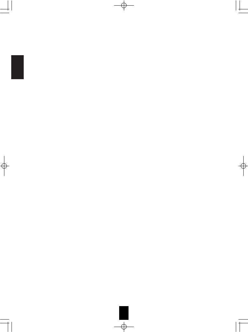
3. CONNECTING AUDIO COMPONENTS
•For analog audio recording, the ROOM 2 OUT jacks can be connected
to audio recording equipment such as a tape deck, an MD recorder, etc. as shown beside.
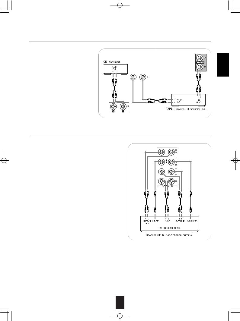
4. CONNECTING EXTERNAL INS
•Use these jacks to connect the corresponding outputs of a DVD player or external decorder, etc. that has 6, 7 or 8 channel analog audio outputs.
•In case of 6 or 7 channel outputs, do not connect both of the SURROUND BACK L and R inputs or the SURROUND BACK R input of this unit. (For details, refer to the operating instructions of the component to be connected.)
ENGLISH
7
R-772(G)2007.9.174:43PM 8
ENGLISH
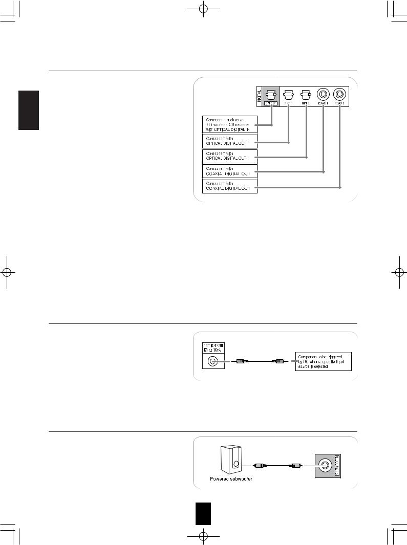
5. CONNECTING DIGITAL INS AND OUT
•The OPTICAL and the COAXIAL DIGITAL OUTs of the components that are connected to this unit
can be connected to these DIGITAL INs.
• A digital input should be connected to the components such as a CD player, DVD player, etc. capable of outputting DTS Digital Surround, Dolby Digital or PCM format digital signals, etc.
• If the component with OPTICAL IN jack is connected to the OPTICAL OUT jack of this unit, you can record the high quality sound of CDs, etc. without degradation.
• For details, refer to the operating instructions of the component connected.
• When making the COAXIAL DIGITAL connection, be sure to use a 75 Ω COAXIAL cord, not a conventional AUDIO cord.
•All of the commercially available optical fiber cords cannot be used for the equipment. If there is an optical fiber cord which cannot be connected to your
organization.
Notes:
•Be sure to make either a OPTICAL or a COAXIAL do both.)
•Depending on the digital audio signal format input output from the OPTICAL OUT jack.
Digital input default settings
•If you connect the DIGITAL INs to your components,
•If your DIGITAL connections are different from default with the “When selecting the AUDIO ASSIGN”
•The default settings are as follows :
OPTICAL IN 1 : VIDEO 1, OPTICAL IN 2 : VIDEO
6. CONNECTING DC TRIGGER OUT
•Connect a component to DC TRIGGER OUT jack that allows DC 12V to turn on when a specific
input source is selected.
• For details, refer to the operating instructions of the components to be connected.
• To link DC TRIGGER OUT with a specific input source, refer to "When selecting the DC TRIGGER" on page 46.
Note:
•This output voltage (12V d.c., 100mA) is for (status)
•When making DC TRIGGER connection, you should
7. CONNECTING SUBWOOFER PREOUT
• To emphasize the deep bass sounds, connect a powered subwoofer.
8
R-772(G)2007.9.174:43PM 9
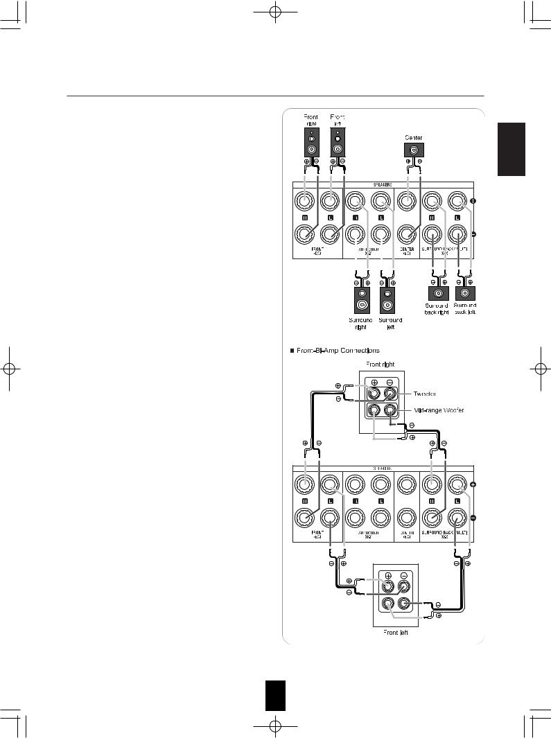
8. CONNECTING SPEAKERS
•Be sure to connect speakers firmly and correctly according to the channel(left and right) and the polarity (+ and -). If the connections are faulty, no sound will be heard from the speakers, and if the polarity of the speaker connection is incorrect, the sound will be unnatural and lack bass.
•For installing the speakers, refer to “Speaker placement” on page 10.
•After installing the speakers, first adjust the speaker settings according to your environment and speaker layout. (For details, refer to “SETTING THE SPEAKER/ROOM EQ SETUP” on page 48.)
Surround back speakers
•When using only one surround back speaker, you should connect it to SURROUND BACK/MULTI LEFT channel.
•Because this receiver cannot drive the surround back speakers and the ROOM 2 speakers simultaneously, you should assign their power amplifier correctly depending on how to use them.
(For details, refer to “CONNECTING ROOM 2 OUTS” on page 11 and “When selecting the AMP ASSIGN” on page 40.)
Front Bi-Amp Connections.
•Some speakers are equipped with two sets of input terminals, for bi-amplification.
•If no other surround back speakers are used, you can connect the FRONT and the SURROUND BACK /MULTI channels to the bi-amp-capable speakers. (For details, refer to the operating instructions of your bi-amp-capable speakers.)
•To drive the bi-amp-capable speakers, you should assign the power amplifier to "BI-AMP".
Note :
•Before making bi-amp connections, remove the short-circuiting bars from the terminals of your speakers.
Caution :
•Be sure to use the speakers with the impedance of 6 ohms or above.
•Do not let the bare speaker wires touch each other or any metal part of this unit. This could damage this unit and/or the speakers.
ENGLISH
9
R-772(G)2007.9.174:43PM 10
ENGLISH
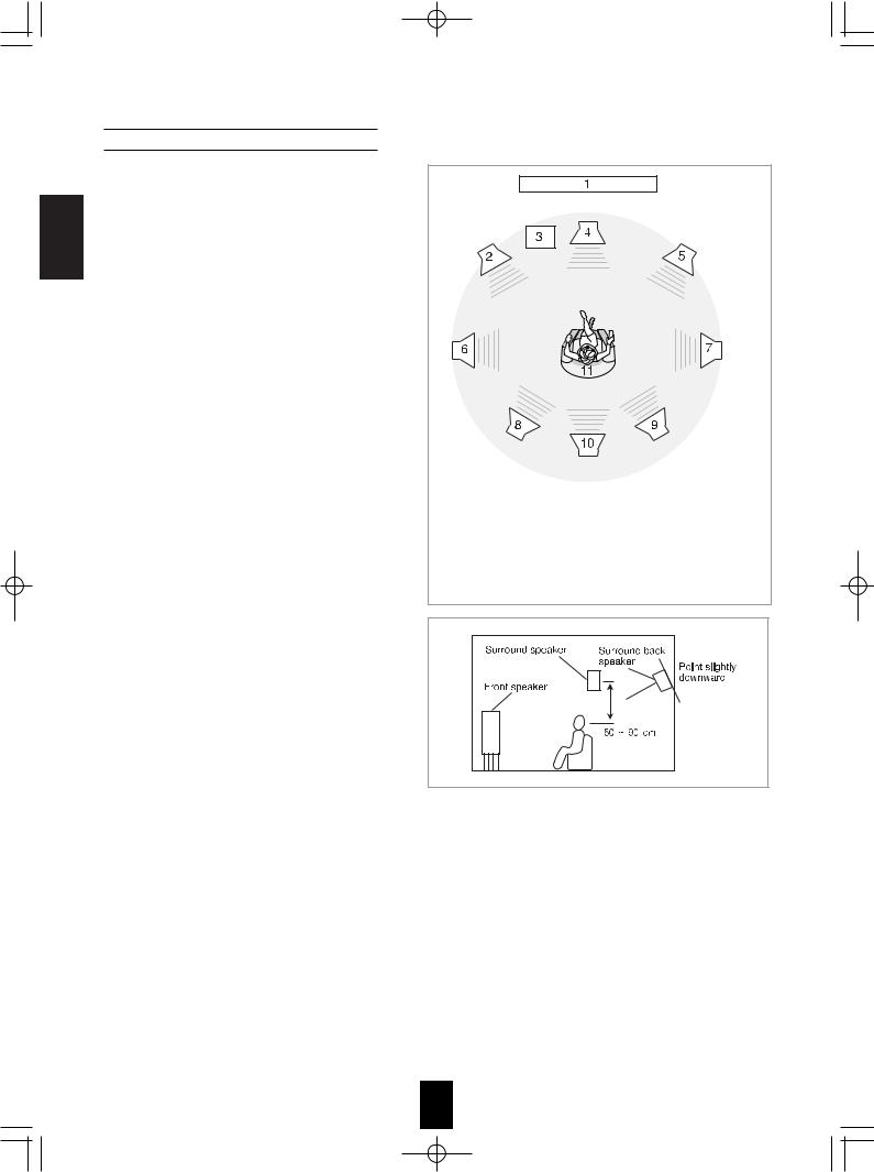
Speaker placement
Ideal speaker placement varies depending on the size of your room and the wall coverings, etc. The typical example of speaker placement and recommendations are as follows :
■Front left and right speakers and center speaker
•Place the front speakers with their front surfaces as flush with TV or monitor screen as possible.
•Place the center speaker between the front left and right speakers and no further from the listening position than the front speakers.
•Place each speaker so that sound is aimed at the location of the listener’s ears when at the main listening position.
■Surround left and right speakers
•Place the surround speakers approximately 1 meter (40 inches) above the ear level of a seated listener on the direct left and right of them or slightly behind.
■Surround back left and right speakers
•Place the surround back speakers at the back facing the front at a narrower distance than front speakers.
•When using a single surround back speaker, place it at the rear center facing the front at a slightly higher position (0 to 20 cm ) than the surround speakers.
•We recommend installing the surround back speaker(s) at a slightly downward facing angle. This effectively prevents the surround back channel signals from reflecting off the TV or screen at the front center, resulting in interference and making the sense of movement from the front to the back less sharp.
■Subwoofer
•The subwoofer reproduces powerful deep bass sounds.
Place a subwoofer anywhere in the front as desired.
1. |
TV or Screen |
7. |
Surround right speaker |
|
2. |
Front left speaker |
8. |
Surround back left speaker |
|
3. |
Subwoofer |
9. |
Surround back right speaker |
|
4. |
Center speaker |
10. |
Surround center speaker |
|
5. |
Front right speaker |
11. |
Listening position |
|
6. |
Surround left speaker |
|
|
|
■Notes :
When using a conventional TV, to avoid interference with the TV picture, use only magnetically shielded front left and right and center speakers.
To obtain the best surround effects, the speakers except the subwoofer should be full range speakers.
10
R-772(G)2007.9.174:43PM 11
9. CONNECTING ROOM 2 OUTS
• ROOM 2 playback feature allows you to play a different program source in another room as well as one source |
|
|
in the main room at the same time. |
|
|
• For ROOM 2 playback, connect the ROOM 2 OUT jacks to the amplifier, TV, etc. installed in another room, or |
ENGLISH |
|
connect the ROOM 2 speaker terminals to the speakers. |
||
|
||
• Because this receiver cannot drive the surround back speakers and the ROOM 2 speakers simultaneously, you |
|
|
should assign their power amplifier correctly depending on how to use them. (For details, refer to "When |
|
|
selecting the AMP ASSIGN" on page 40.) |
|
|
• When the ROOM 2 (AUDIO) OUT jacks are not connected to the ROOM 2 amplifier, you can connect these |
|
|
jacks to audio recording equipment such as a tape deck, an MD recorder, etc. for analog audio recording. (For |
|
|
details, refer to "CONNECTING AUDIO COMPONENTS" on page 7.) |
|
Notes :
•To minimize hum or noise, use high quality connection cords.
•You cannot use the digital audio signal for ROOM 2 playback.
10. CONNECTING PC FOR UPGRADES
•This receiver incorporates USB as well as RS-232C terminal that may be used in the future to update the operating software so that it will be able to support new digital audio formats, external control by using an external device and the like.
•Connect either USB or RS-232C terminal to your PC (you don't need to do both).
Notes:
•Programming for upgrades and external control requires specialized programming knowledge and for that reason we installers. For more information on future upgrades and external www.sherwoodamerica.com or contact your dealer.
•Do not disconnect the connection cable while updating the Should this happen, it may be result in malfunction or cause
11
ENGLISH
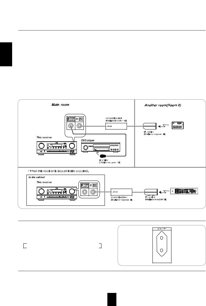
11. CONNECTING MULTI-ROOM SYSTEM KIT
• The multi-room system kit(sold separately ) is essential for operation from a remote location .
For information on the multi-room system kit, contact the Xantech corporation at 1-800-843-5465 or www.xantech.com.
•IR IN jack allows you to control this receiver from another room with the remote control unit.
•To control this receiver from another room with the remote control unit, connect the IR IN jack to the output of the connecting block.
•If this receiver is located inside a cabinet or other enclosure where the infrared beams from the remote control unit cannot enter, then operation with the remote control unit will not be possible. In such a case, connect the IR IN jack to the output of the connecting block.
•To control other compatible component from another room with the universal remote control unit, connect the IR OUT jack to the IR emitter.
Note:
•Remote operation may become unreliable if the IR receiver is exposed to strong light such as direct sunlight or inverted fluorescent.
12. SWITCHED AC OUTLET
• This outlet is switched on (power-on mode) and off (standby mode) according to power control as follows (Maximum total capacity is 100 W (0.43A)).
Standby mode - Switched AC outlet off
Power - on mode - Switched AC outlet on
13. AC INPUT CORD
• Plug this cord into a wall AC outlet.
12
R-772(G)2007.9.174:43PM 13
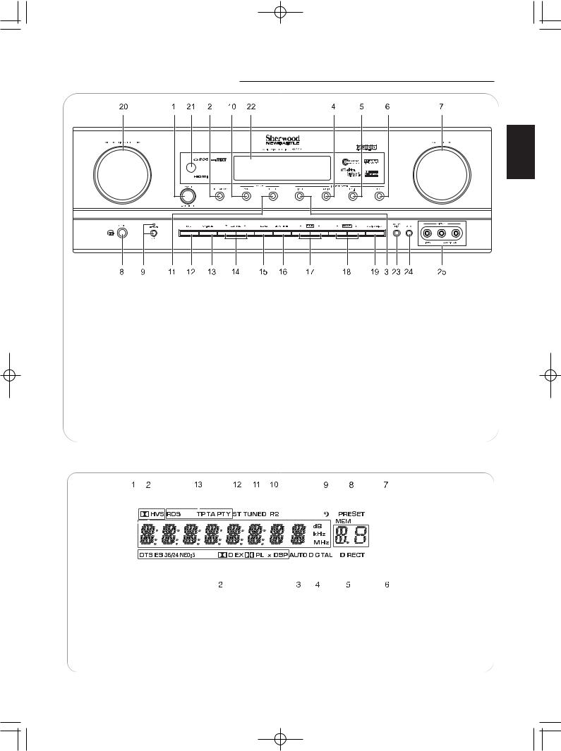
Front Panel Controls
ENGLISH
1. POWER switch |
16. MEMORY/ENTER button |
||
2. |
POWER ON/STANDBY button/indicator |
17. |
TUNING UP/DOWN(+/-) buttons |
3. VIDEO INPUT SELECTOR button |
18. PRESET UP/DOWN(+/-) buttons |
||
4. AUDIO INPUT SELECTOR button |
19. AUDIO ASSIGN button |
||
5. EXTERNAL IN button |
20. MULTI CONTROL knob |
||
6. TUNER button |
21. REMOTE SENSOR |
||
7. MASTER VOLUME CONTROL knob |
22. FLUORESCENT DISPLAY |
||
8. |
HEADPHONE jack |
|
For details, see below. |
9. |
SPEAKER button/indicator |
23. |
SETUP MIC jack |
10. |
SURROUND MODE button |
|
For details, see next page. |
11. |
STEREO button |
24. |
AUX IN jack |
12. |
SETUP button |
|
For details, see next page. |
13. |
CHANNEL LEVEL button |
25. |
VIDEO 4 IN jacks |
14. |
CONTROL UP/DOWN (▲/▼) buttons |
|
For details, see next page. |
15. ROOM 2 button
FLUORESCENT DISPLAY
|
|
|
|
|
|
|
|
|
|
|
|
|
|
|
|
|
|
|
|
|
|
|
|
|
|
|
|
|
|
|
|
|
|
|
|
|
|
|
|
|
|
|
|
|
|
|
|
|
|
|
|
|
|
|
|
|
|
|
|
|
|
|
|
|
|
|
|
|
|
|
|
|
|
|
|
|
|
|
|
|
|
|
|
|
|
|
|
|
|
|
|
|
|
|
|
|
|
|
|
|
|
|
|
|
|
|
|
|
|
|
|
|
|
|
|
|
|
|
|
|
|
|
|
|
|
|
|
|
|
|
|
|
|
|
|
|
|
|
|
|
|
|
|
|
|
|
|
|
|
|
|
|
|
|
|
|
|
|
|
|
|
|
|
|
|
|
|
|
|
|
|
|
|
|
|
|
|
|
|
|
|
|
|
|
|
|
|
|
|
|
|
|
|
|
|
|
|
|
|
|
|
|
|
|
|
|
|
|
|
|
|
|
|
|
|
|
|
|
|
|
|
|
|
|
|
|
|
|
|
|
|
|
|
|
|
|
|
|
|
|
|
|
|
|
|
|
|
|
|
|
|
|
|
|
|
|
|
|
|
|
|
|
|
|
|
|
|
|
|
1. |
Input, frequency, volume level, operating information, etc. |
8. |
PRESET indicator |
|||||||||||||||||||||||
2. |
Surround mode indicators |
9. |
SLEEP indicator |
|||||||||||||||||||||||
3. |
AUTO indicator |
10. |
ROOM 2 indicator |
|||||||||||||||||||||||
4. |
DIGITAL INPUT indicator |
11. |
TUNED indicator |
|||||||||||||||||||||||
5. |
DIRECT indicator |
12. |
STEREO indicator |
|||||||||||||||||||||||
6. |
Preset number, sleep time display |
13. |
RDS indicators |
|||||||||||||||||||||||
7. |
MEMORY indicator |
|
|
|
|
(Regional option for Europe, etc.) |
||||||||||||||||||||
|
|
|
|
|
|
|
|
|
|
|
|
|
|
|
|
|
|
|
|
|
|
|
|
|
|
|
|
|
|
|
|
|
|
|
|
|
|
|
|
|
|
|
|
|
|
|
|
|
|
|
|
|
|
R-772(G)2007.9.174:43PM 14
ENGLISH
SETUP MIC JACK
•To use Auto Setup function, connect the supplied microphone to the SETUP MIC jack.(For details, refer to "When selecting the AUTO SETUP" on page 48.)
Notes:
•Because the microphone for Auto Setup is designed for use with this receiver, do not use a microphone other than the one supplied with this receiver.
•After you have completed the auto setup procedure, disconnect the microphone.
AUX IN JACK
•The AUX IN jack can be connected to an additional audio component such as an MP3 player, etc.
Note :
•When connecting this jack to an MP3 player, etc., you should use the stereo mini cord, not a mono mini cord.
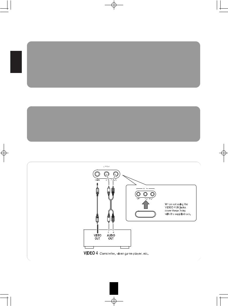
VIDEO 4 IN JACKS
•The VIDEO 4 IN jacks may be also connected to an additional video component such as a camcorder, a video game player, etc.
14
R-772(G)2007.9.174:43PM 15
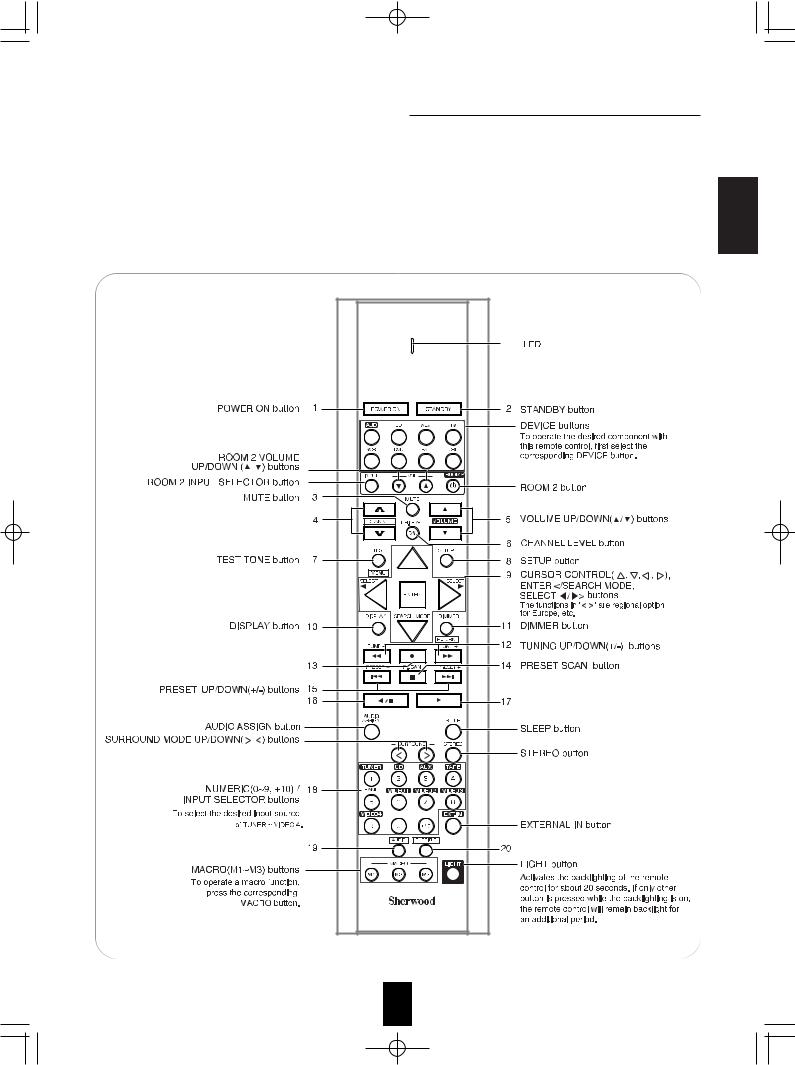
Universal Remote Controls
This universal remote control can operate not only this receiver but also most popular brands of audio and video components such as CD players, tape decks, TVs, cable boxes, VCRs, DVD players, satellite receivers, etc.
•To operate 7 components other than this receiver , you should enter the setup code for each component. (For details, refer to “USING FUNCTIONS OF REMOTE CONTROL” on page 18.)
•The numbered buttons on the remote control have different functions in different device modes. For details,
refer to "FUNCTION TABLE of the NUMBERED BUTTONS" on the next page.Note :
•In such a case that some components do not have the REMOTE SENSOR which receives the remote signals, this remote control cannot operate them.
15 |
ENGLISH

R-772(G)2007.9.174:43PM 16
FUNCTION TABLE of the NUMBERED BUTTONS. |
|
ENGLISH |
|
Notes : |
|
• Some functions for each component may not be available or may |
work differently. |
• Depending on other kinds of components that are available for each DEVICE button, some functions may not be |
|
available or may work differently, too. |
|
• For details about functions, refer to the operating instructions of each component. |
|
16 |
|
R-772(G)2007.9.174:43PM 17
OPERATING COMPONENTS WITH REMOTE CONTROL 
1. Enter the setup code for each component other
than this receiver. For detalis, refer to “Entering a setup code” on page 18.
2. Turn on the component you want to operate.
3. Press the DEVICE button on the remote control
corresponding to the component you wish to operate.
4. Aim the remote control at the REMOTE
SENSOR of the component you wish to control and press the button corresponding to the operation you want.
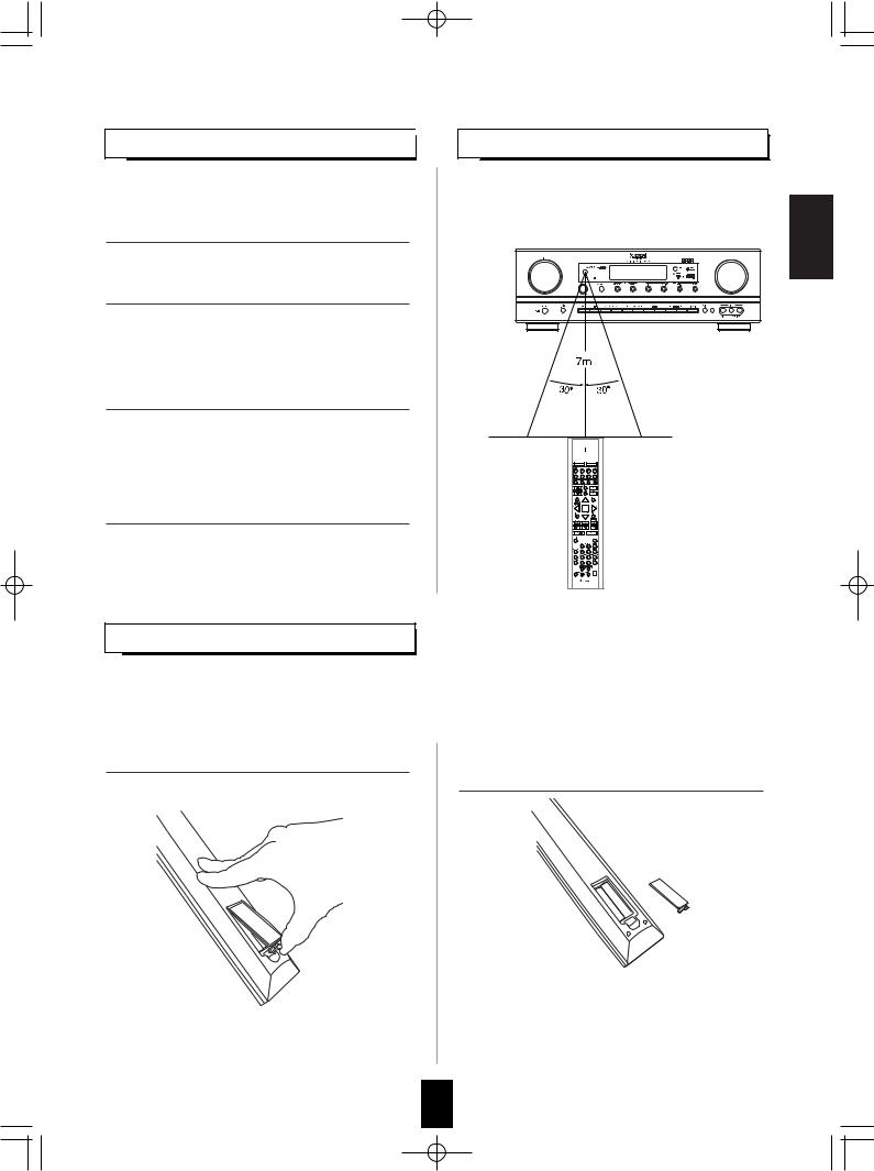
LOADING BATTERIES
REMOTE CONTROL OPERATION RANGE
•Use the remote control within a range of about 7 meters (23 feet) and angles of up to 30 degrees aiming at the remote sensor.
When the remote control does not operate, the old batteries should be replaced. In this case, load new batteries within several minutes after removing old batteries.
If the betteries are removed or have been exhausted for a longer period of time, memorized contents will be cleared. Should this happen, you should memorize them again.
1. Remove the cover.
+ 
2. Load two batteries (“AAA” size) matching the
polarity.
+
+
•Remove the batteries when they are not used for a long time.
•Do not use the rechargeable batteries (Ni-Cd type).
•Be sure to use alkaline batteries.
ENGLISH
17
R-772(G)2007.9.174:43PM 18
USING FUNCTIONS OF REMOTE CONTROL
|
|
• This remote control can control up to 8 different components. |
|
|
|
• Before operating audio and video components other than this receiver with using this remote control, the |
|
ENGLISH |
|
setup code for each component should be entered. |
|
|
• For system remote control operation, “000” was stored previously in the memory of the device button “CD” for |
||
|
|
||
|
|
Sherwood CD player, “DVD” for Sherwood DVD player, "AUX" for Sherwood tape deck and "TV" for Sherwood TV |
|
|
|
respectively as its factory setup code. So, you don’t need to enter its code for each Sherwood component except |
|
|
|
in such a case that its code does not work. |
|
|
|
|
|
Entering a setup code
1. |
Turn on the component you want to control. |
4. Enter a 3 digit code, aiming the remote control at |
|
|
the remote sensor on the component. |
|
|
Example) When entering "001". |
2. |
Find the setup codes according to the type and |
|
|
the brand name of your component, referring to |
|
|
“Setup Code Table” on page 64. |
|
3. Press and hold down both the "ENTER" button and the desired one of the DEVICE buttons for more than 1 second.
|
• If entering is performed successfully, the LED will |
|
|
flicker twice. |
|
|
• To be sure that the setup code is correct, press the |
|
|
POWER ON(or STANDBY) button. |
|
|
If your component is tuned off, the setup code is |
|
|
correct. |
|
|
• When your component is not turned off, repeat the |
|
|
above steps 2 to 4, trying each code for your |
|
|
component until you find one that works. |
|
|
Notes: |
|
|
• If the LED did not flicker twice, then repeat the |
|
• The LED will flicker once. |
above steps 3 to 4 and try entering the same |
|
code again. |
||
|
||
Note : |
• Manufacturers may use different setup codes for |
|
the same product category. For that reason, it is |
||
• The "AUD" button is unavailable for the audio |
||
important that you check to see if the code you |
||
components other than this receiver. |
||
have entered operates as many controls as |
||
|
||
|
possible. If only a few functions operate, check to |
|
|
see if another code will work with more buttons. |
|
|
5. Repeat the above steps 1 to 4 for each of your |
|
|
components. |
18
R-772(G)2007.9.174:43PM 19
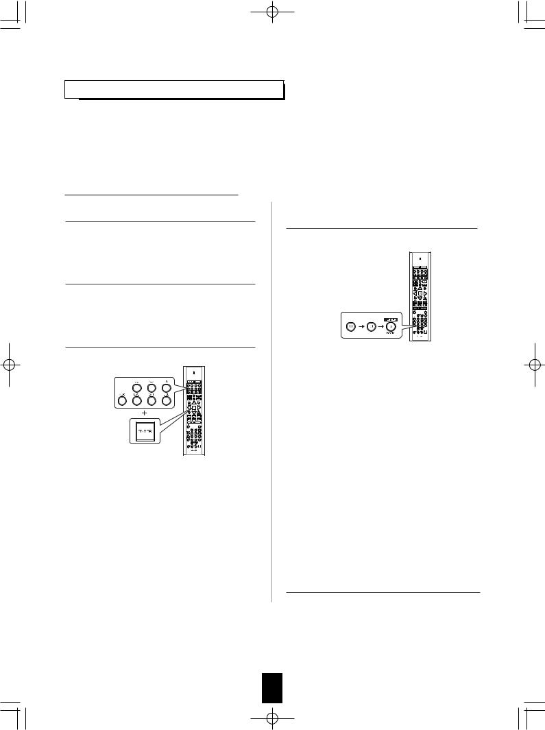
Using a punch-through function
This remote control may be programmed to operate either the AUDIO volume punch-through or the TV volume and/or TV channel punchthrough in conjunction with any of the eight components controlled by this remote control. For example, since this receiver will likely be used as the sound system while watching TV, you may want to adjust this receiver’s volume although this remote control is set to control the TV.
•When programming this remote control for the AUDIO volume punch-through, press and hold down both "AUD" button and "VOLUME ▲" button for more than 1 second.
•If programming is performed successfully, the LED will flicker twice.
•When you want either TV volume or TV channel punch-through, press and hold down both "TV" button and either "VOLUME ▲" or "CHANNEL ▲" button for more than 1 second.
Note:
•If you use one of AUDIO and TV volume punch-through functions, you cannot use the other.
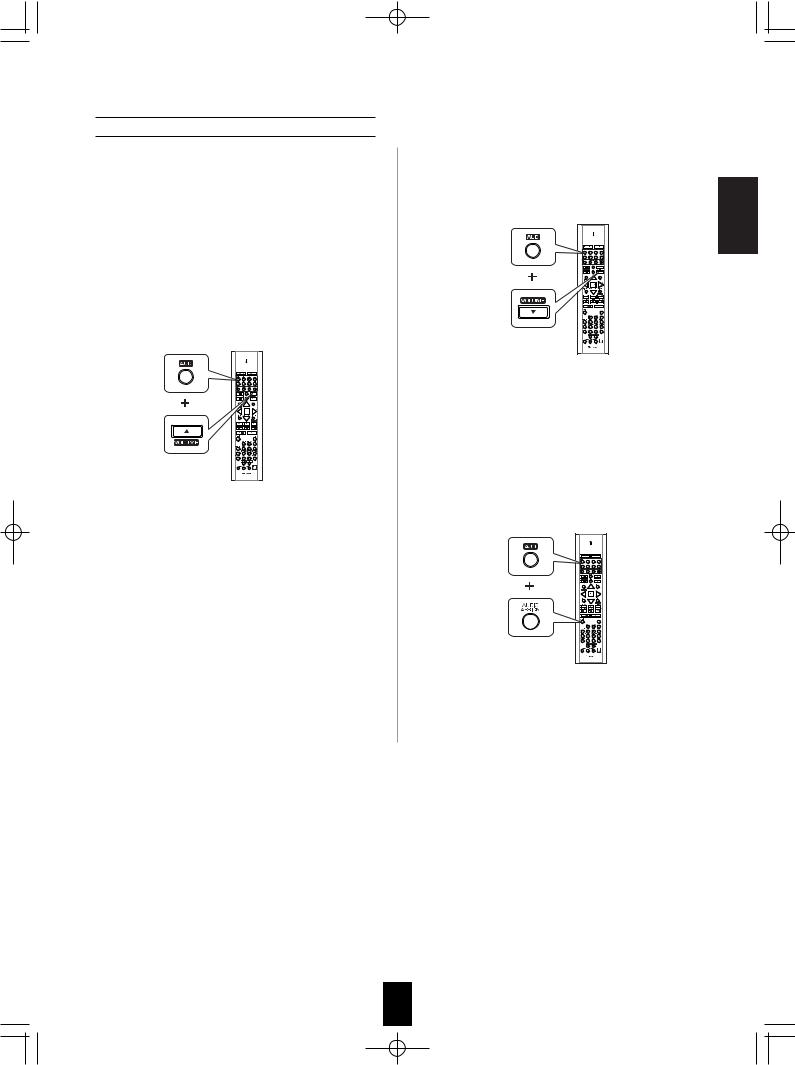
Removing a punch-through function
•When removing the AUDIO volume punch-through, press and hold down both "AUD" button and "VOLUME ▼" button for more than 1 second.
•If removing is performed successfully, the LED will flicker twice.
•When you want to remove either TV volume or TV channel punch-through, press and hold down both "TV" button and either "VOLUME ▼" or "CHANNEL ▼" button for more than 1 second.
Removing all punch-through functions
Press and hold down both "AUD" button and "AUDIO ASSIGN" button for more than 1 second.
•If removing all punch-through functions is performed successfully, the LED will flicker twice.
ENGLISH
19
R-772(G)2007.9.174:43PM 20
ENGLISH
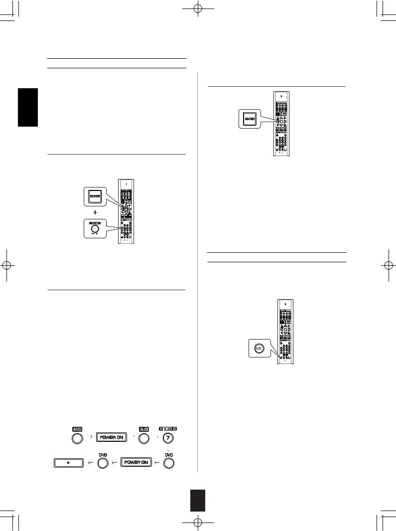
Programming a macro function
•The macro function enables you to program a series of button operations(up to 10) on this remote control into a single button.
•You can store up to three separate macro command sequences into “M1”, “M2” and “M3” buttons.
1. Press and hold down both "ENTER" button and one of three NUMERIC buttons ("1"~"3") corresponding to "M1"~"M3" buttons for more than 1 second.
Example) When programming a series of button operations into "M1" button.
•If the macro mode is entered, the LED will flicker once.
2. Press the operation buttons you want to program in order.
Note:
You should press the corresponding DEVICE buttons before pressing each operation button. Example) When playing a DVD on the DVD player
connected to VIDEO 2 jacks of this receiver.
. Press "AUD" button to control this receiver.. Press "POWER ON" button to turn this
receiver on.
. Press "AUD" button to control this receiver.. Press "VIDEO 2(7)" button to select the
desired input source.
. Press "DVD" button to control the DVD player.. Press "POWER ON" button to turn the DVD
player on.
. Press "DVD" button to control the DVD player.. Press " " button to start playback.
3. Press "ENTER" button.
•If the programming is performed successfully, the LED will flicker twice.
To remove a macro program
•When removing a macro program, perform the above steps 1 and 3, but ignore the step 2.
To change a macro program
•When a new macro program is stored into a MACRO button with performing the above steps 1 to 3, the previous macro program is cleared from the memory of the MACRO button.
Operating a macro function
•Aim the remote control at the REMOTE SENSORs of the components to be controlled and press the MACRO button you want. Example) When pressing “M1” button.
Notes:
•The codes programmed into a MACRO button will be transmitted at an interval of 0.5 seconds. However, some components may not be able to complete one operation in 0.5 seconds and may miss the next code.
In this case, the macro function cannot control the corresponding components correctly.
•Be sure to use the remote control within the remote control operation range of the components.
•Depending on the operation status of the components, etc., the macro function cannot control the corresponding components correctly.
20
R-772(G)2007.9.174:43PM 21
ROOM 2 Remote Controls
This remote control unit is an additional remote control unit for the ROOM 2 source playback only.
•You can use the ROOM 2 functions with this remote control unit more conveniently in another room than with the universal remote control unit.
•For details on ROOM 2 operation, refer to "ROOM 2 SOURCE PLAYBACK" on page 35.
REMOTE CONTROL OPERATION RANGE
• Aim the ROOM 2 remote control(or the universal remote control) at the IR receiver installed in another room.(For details, refer to “CONNECTING MULTI-ROOM SYSTEM KIT” on page 12.)
• When you operate the ROOM 2 function in the main room, aim the universal remote control (or the ROOM 2 remote control) at the remote sensor of this receiver.
LOADING BATTERY
1. Remove the cover. |
2. Load the battery(CR2025) matching the polarity. |
the battery when it is not used for a long
ENGLISH
21
 Loading...