


RD-7103
REMOTE
SENSOR
MASTER VOLUME
TONE
DIRECT
ON/STANDBY
MAIN POWER
STANDBY
ON/ OFF
TUNING/PRESETADJUST
PHONES
CHANNEL
SELECTOR
VIDEO L - AUDIO - R
VIDEO 3
BANDFM MODET/P MODETONE MODE
SPEAKER
MODE
DYNAMIC
RANGE
MEMO/ENTERCINEMA EQ
ON/OFF
SPEAKER
INPUT SELECTOR
AUDIO
VIDEO TAPE MON.
6CH DIRECT DSP MODEAUTO STEREO
DIGITAL
INPUTS
TONE
DIRECT
SURROUND MODE
TOTALLY DISCRETE AMPLIFIER STAGE
TDAS
ST TUNED TAPE M PRESET
Pro LogicDIGITAL
DTS
THEATER HALL SLEEP
dB
kHz
MHz
MEM
ms
RRDD--77110033
AUDIO/VIDEO RECEIVER
OPERATINGINSTRUCTIONS
2
IInnttrroodduuccttiioonn
Congratulations on Your Purchase!
Your new high fidelity receiver is designed to deliver
maximum enjoyment and years of trouble free service.
Please take a few moments to read this manual
thoroughly. It will explain the features and operation of
your unit and help ensure a trouble free installation.
Please unpack your unit carefully. We recommend that
you save the carton and packing material. They will be
helpful if you ever need to move your unit and may be
required if you ever need to return it for service. Your unit
is designed to be placed in a horizontal position and it is
important to allow at least two inches of space behind
your unit for adequate ventilation and cabling
convenience.
To avoid damage, never place the unit near radiators, in
front of heating vents, in direct sunlight, or in excessively
humid or dusty locations. Connect your complementary
components as illustrated in the following section.
CAUTION : TO REDUCE THE RISK OF
ELECTRIC SHOCK, DO NOT
REMOVE COVER (OR BACK).
NO USER-SERVICEABLE PARTS
INSIDE. REFER SERVICING TO
QUALIFIED SERVICE PERSONNEL.
CAUTION
RISK OF ELECTRIC SHOCK
DO NOT OPEN
This symbol is intended to alert the user to the
presence of uninsulated "dangerous voltage"
within the product's enclosure that may be of
sufficient magnitude to constitute a risk of
electric shock to persons.
This symbol is intended to alert the user to the
presence of important operating and
maintenance (servicing) instructions in the
literature accompanying the appliance.
To reduce the risk of fire or electric shock, do not expose
this appliance to rain or moisture.
Caution : Do not block ventilation openings or stack
other equipment on the top.
FOR U.S.A.
Note to CATV System Installer: This reminder is
provided to call the CATV system installer's attention
to Article 820-40 of the NEC that provides guidelines
for proper grounding and, in particular, specifies that
the cable ground shall be connected to the
grounding system of the building, as close to the
point of cable entry as practical.
FCC INFORMATION
This equipment has been tested and found to
comply with the limits for a Class B digital device,
pursuant to Part 15 of the FCC Rules. These limits
are designed to provide reasonable protection
against harmful interference in a residential
installation. This equipment generates, uses and can
radiate radio frequency energy and, if not installed
and used in accordance with the instructions, may
cause harmful interference to radio communications.
However, there is no guarantee that interference will
not occur in a particular installation. If this equipment
does cause harmful interference to radio or
television reception, which can be determined by
turning the equipment off and on, the user is
encouraged to try to correct the interference by one
or more of the following measures:
Reorient or relocate the receiving antenna.
Increase the separation between the equipment
and receiver.
Connect the equipment into an outlet on a circuit
different from that to which the receiver is
connected.
Consult the dealer or an experienced radio/TV
technician for help.
CAUTION: Any changes or modifications in
construction of this device which are not expressly
approved by the party responsible for compliance
could void the user's authority to operate the
equipment.
WARNING
UNPACKING AND INSTALLATION
Caution regarding placement
(Except for U.S.A. and Canada)
To maintain proper ventilation, be sure
to leave a space around the unit (from
the largest outer dimensions including projections)
equal to, or greater than, shown below.
Left and right panels: 5 cm
Rear panel: 10 cm
Top panel: 20 cm
EENNGGLLIISSHH
FOR U.S.A. AND CANADA ....................................120 V
Units shipped to the U.S.A. and Canada are designed
for operation on 120 volts AC only.
Observe all safety precautions for use of a polarized
AC plug. However, some products may be supplied
with a non polarized plug.
CAUTION : To prevent electric shock, match wide
blade of plug to wide slot, insert fully.
FOR YOUR SAFETY
FOR EUROPE AND AUSTRALIA .........230V/240V
Units shipped to Australia are designed for operation
on 240 V AC only.
To ensure safe operation, the three-pin plug supplied
must be inserted only into a standard three-pin
power point which is effectively earthed through the
normal household wiring. Extension cords used with
the equipment must be three-core and be correctly
wired to provide connection to earth.
Improper extension cords are a major cause of
fatalities. The fact that the equipment operates
satisfactorily does not imply that the power point is
earthed and that the installation is completely safe.
For your safety, if in any doubt about the effective
earthing of the power point, consult a qualified
electrician.
PAN-EUROPEAN UNIFIED VOLTAGE
All units are suitable for use on supplies 230-240 V
AC.
FOR YOUR SAFETY
3
READ THIS BEFORE OPERATING YOUR UNIT
FOR OTHER COUNTRIES ........................ 115 V/230 V
Units shipped to countries other than the above
countries are equipped with an AC voltage selector
switch on the rear panel. Refer to the following
paragraph for the proper setting of this switch.
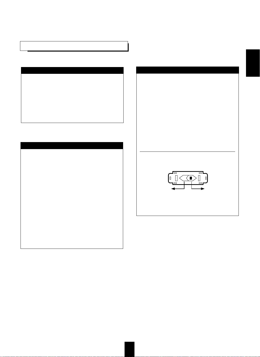
AC VOLTAGE SELECTION
This unit operates on 115/230 V AC. The AC voltage
selector switch on the rear panel is set to the voltage
that prevails in the area to which the unit is shipped.
Before connecting the power cord to your AC outlet,
make sure that the setting position of this switch
matches your line voltage. If not, it must be set to
your voltage in accordance with the following
direction.
AC voltage selector switch
Move switch lever to match your line voltage with a
small screwdriver or other pointed tool.
FOR YOUR SAFETY
AC 230 V AC 115 V
EENNGGLLIISSHH

4
CONTENTS
Introduction
UNPACKING AND INSTALLATION ....................................................................................................... 2
READ THIS BEFORE OPERATING YOUR UNIT................................................................................... 3
System Connections........................................................................................................................................ 5
Front Panel Controls...................................................................................................................................... 8
DIGI LINK IIISystem Remote Controls................................................................................................... 9
REMOTE CONTROL OPERATION RANGE.......................................................................................... 10
LOADING BATTERIES............................................................................................................................ 10
Operations
LISTENING TO A PROGRAM SOURCE................................................................................................ 11
SURROUND SOUND................................................................................................................................ 14
ENJOYING SURROUND SOUND........................................................................................................... 15
LISTENING TO RADIO BROADCASTS ................................................................................................ 19
RECORDING ............................................................................................................................................. 21
OTHER FUNCTIONS................................................................................................................................ 22
Troubleshooting Guide................................................................................................................................23
Specifications.................................................................................................................................................. 24
EENNGGLLIISSHH
5
SSyysstteemm CCoonnnneeccttiioonnss
Manufactured under license from Digital Theater Systems, Inc.
US Pat. No. 5,451,942 and other world-wide patents issues and pending.
“DTS” and “DTS Digital Surrou emarks of Digital Theater Systems, Inc.
©1996 Digital Theater Systems, Inc. All rights reserved.
Manufactured under license from Dolby Laboratories. “Dolby”, “Pro Logic”
and the double-D symbol are trademarks of Dolby Laboratories. Confidential
Unpublished Works. ©1992-1997 Dolby Laboratories, Inc. All rights reserved.
MODEL NO. RD
-
7103
AUDIO/VIDEO RECEIVER
MADE IN CHINA
DESIGNED IN USA
SWITCHED
120V~60Hz
100W 1A MAX
AC OUTLET
OPTICAL
COAX 1 COAX 2
AC INPUT
120V~60Hz
180W
SER. NO
This device complies with Part 15 of the FCC Rules.
Operation is subject to the following two conditions:
(1)This device may not cause harmful interference, and
(2)this device must accept any interference received,
including interference that may cause undesired operation.
CAUTION
RISK OF ELECTRIC SHOCK
DO NOT OPEN
WARNING:"SHOCK HAZARD-DO NOT OPEN"
AVIS;"RISQUE DE CHOC-ELECTRQUE-NE PAS OUVRIR"
AM
LOOP
FM
75
Ω
ANTENNA
AUX PLAY REC PLAY REC PLAY VIDEO 1
VIDEO 2
SUB
WOOFER
TAPE MON. VIDEO 1CDVIDEO 2
MONITOR
PRE OUT
VIDEO
OUT
DIGI
-LINK
VIDEO
IN
VIDEO 1
SUB
WOOFER
CENTER
FRONT REAR
L
R
6-CH DIRECT INPUT
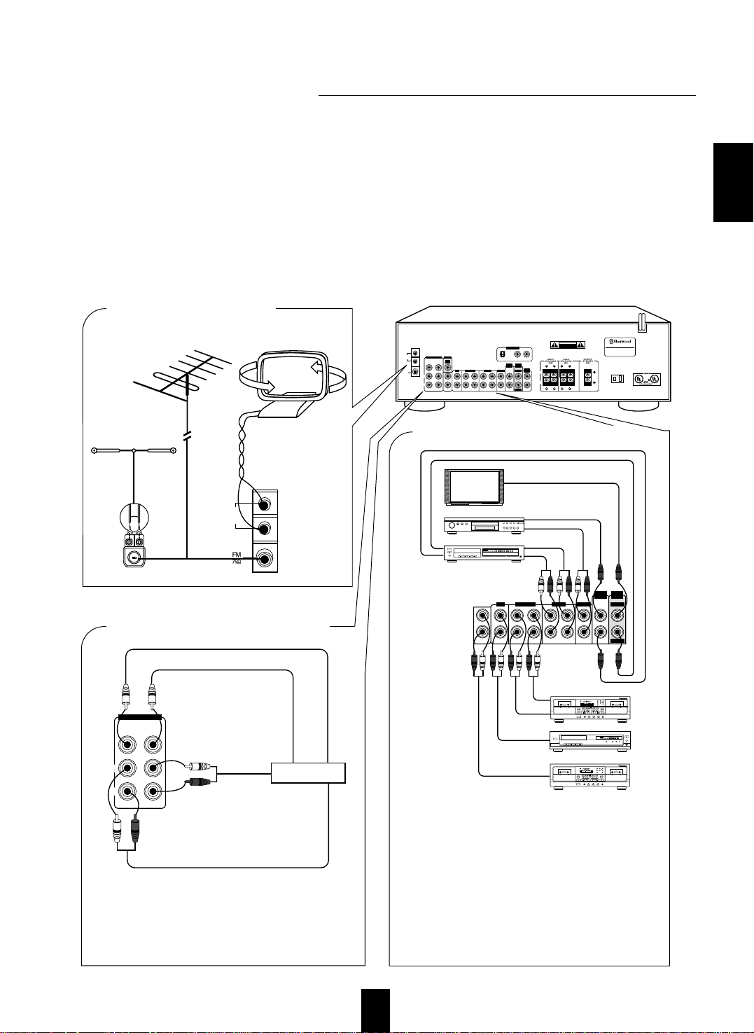
■ CONNECTING ANTENNAS
AM loop antenna
FM
FM
(INDOOR ANTENNA)
(OUTDOOR ANTENNA)
SUPPLIED ADAPTOR
300 ohm
feeder
AM
LOOP
Tape deck or additional audio component
BC
NORMHIGH
SYNMPX MIN SEC
RELAY
REC
P
CD
M
REC
L
R
dB-00-20 -10 -6 -3 0 +3 +6
DIGI-LINK STEREO DOUBLE CASSETTE DECK DD-5080C
AUTO REVERSE
PLAY/AUTO TAPE SELECTOR RECORD & PLAY/AUTO TAPE SELECTOR
HX-PRO
AUTO REVERSE
RESET A/B MODE
R PLAY
DUBBING O/O CD SUN REC
HIGHNORMAL
AMS AMS
EJECT
REC BALAMCEREC LEVELPHONESPOWER MIC MIX
MICSOURCELR0 10
MIC
REVERSE
T SIZEMEMORY B/C/OFF
COUNTER
BA
CD player
POWER
REMOTE SENSOR
PROGRAM/REVIEW
RANDOM REPEAT
OPEN/CLOSE
PHONES LEVEL
PHONES
MIN MAX
ON/OFF
MULTIPLE COMPACT DISC PLAYER CDC-5080R
12 3 4 5
GRAPHICSPEAKDELETE EDIT
SCENETRACK
INDEXSTEP
AB
V-CDPBCREVERT PROGAUTO RANDOMREPEATALL 1DISCS
123
456
789
101112
131415
MPXINTROA< >B
■
CONNECTING AUDIO/VIDEO COMPONENTS
POWER
OPEN/CLOSE
PHONES LEVEL
PHONES
MIN MAX
ON/OFF
MULTIPLE COMPACT DISC PLAYER CDC-5080R
12 3 4 5
GRAPHICSPEAKDELETE EDIT
SCENETRACK
INDEXSTEP
AB
V-CDPBCREVERT PROGAUTO RANDOMREPEAT ALL1DISCS
123
456
789
101112
131415
MPXINTROA< >B
Video deck 1
POWER
ON/OFF
MULTIPLE COMPACT DISC PLAYER CDC-5080R
DVD player or additional video component
Monitor TV
VIDEO OUT
VIDEO OUT
REC(LINE IN)
PLAY(LINE OUT)
PLAY(LINE OUT)
AUDIO OUT
AUDIO OUT
AUDIO IN
VIDEO IN
VIDEO IN
• The VIDEO 2 jacks may also be connected to an additional
video component such as a cable TV tuner, an LD player or
satellite system.
• The TAPE MONITOR PLAY/REC jacks may also be
connected to the LINE OUT/IN jacks of an optional
graphic equalizer.
■Note : When Sherwood DVD player such as V-756, etc. is
connected to the DIGI LINK jack for system
control, you should connect the DVD player to the
"VID 2" jacks of this unit. Then, when the "PLAY"
function of the DVD player is engaged, the receiver
will automatically select "VIDEO 2" as the input
source and playback will start.
BC
NORMHIGH
SYNMPX MIN SEC
RELAY
REC
P
CD
M
REC
L
R
dB-00-20 -10 -6 -3 0 +3 +6
DIGI-LINK STEREO DOUBLE CASSETTE DECK DD-5080C
AUTO REVERSE
PLAY/AUTO TAPE SELECTOR RECORD & PLAY/AUTO TAPE SELECTOR
HX-PRO
AUTO REVERSE
RESET A/B MODE
R PLAY
DUBBING O/O CD SUN REC
HIGHNORMAL
AMS AMS
EJECT
REC BALANCEREC LEVELPHONESPOWER MIC MIX
MICSOURCELR0 10
MIC
REVERSE
T SIZEMEMORY B/C/OFF
COUNTER
BA
*Tape deck or graphic equalizer
AUX PLAY REC PLAY REC PLAY VIDEO 1
VIDEO 2
TAPE MON. VIDEO 1CDVIDEO 2
MONITOR
VIDEO 1
VIDEO
OUT
VIDEO
IN
■ CONNECTING 6 CH DIRECT INPUTS
• Use these jacks to connect the corresponding analog
outputs of 6 CH decoder or DVD player with 6 CH
output for Dolby Digital or DTS, etc.
(For details, see the operator's manual of the component
to be connected.)
6 CH decoder
REAR
CH OUT
CENTER CH OUT
SUBWOOFER CH OUT
FRONT CH OUT
SUB
WOOFER
CENTER
FRONT REAR
L
R
6-CH DIRECT INPUT
L
R
DIGITAL IN
When making system connections, please be certain the AC cord is not plugged into an AC outlet.
When making connections between components, please be sure to connect the white RCA plugs to the L(left) and the red
RCA plugs to the R(right) jacks respectively.
Change the position of the FM indoor antenna until you get the best reception of your favorite FM stations.
A 75 Ω outdoor FM antenna may be used to further improve the reception.
Disconnect the indoor antenna before replacing it with the outdoor one.
Place the AM loop antenna as far as possible from the receiver, TV set, speaker cords and the AC input cord and set it to a
direction for the best reception.
If the reception is poor with the AM loop antenna, an AM outdoor antenna can be used in place of the AM loop antenna.
Make connections firmly and correctly. If not, it can cause loss of sound, noise or damage to the receiver.
If the electricity fails or the AC input cord is left unplugged for more than 2 weeks, the memorized contents will be cleared.
Should this happen, memorize them again.
EENNGGLLIISSHH

6
Manufactured under license from Digital Theater Systems, Inc.
US Pat. No. 5,451,942 and other world-wide patents issues and pending.
“DTS” and “DTS Digital Surrou of Digital Theater Systems, Inc.
©1996 Digital Theater Systems, Inc. All rights reserved.
Manufactured under license from Dolby Laboratories. “Dolby”, “Pro Logic”
and the double-D symbol are trademarks of Dolby Laboratories. Confidential
Unpublished Works. ©1992-1997 Dolby Laboratories, Inc. All rights reserved.
AUDIO/VIDEO RECEIVER
MADE IN CHINA
DESIGNED IN USA
SWITCHED
120V~60Hz
100W 1A MAX
AC OUTLET
OPTICAL
COAX 1 COAX 2
AC INPUT
120V~60Hz
180W
SER. NO
This device complies with Part 15 of the FCC Rules.
Operation is subject to the following two conditions:
(1)This device may not cause harmful interference, and
(2)this device must accept any interference received,
including interference that may cause undesired operation.
CAUTION
RISK OF ELECTRIC SHOCK
DO NOT OPEN
WARNING:"SHOCK HAZARD-DO NOT OPEN"
AVIS;"RISQUE DE CHOC-ELECTRQUE-NE PAS OUVRIR"
AM
LOOP
FM
75
Ω
ANTENNA
AUX PLAY REC PLAY REC PLAY VIDEO 1
VIDEO 2
SUB
WOOFER
TAPE MON. VIDEO 1CDVIDEO 2
MONITOR
PRE OUT
VIDEO
OUT
DIGI
-LINK
VIDEO
IN
VIDEO 1
SUB
WOOFER
CENTER
FRONT REAR
L
R
6-CH DIRECT INPUT
L
R
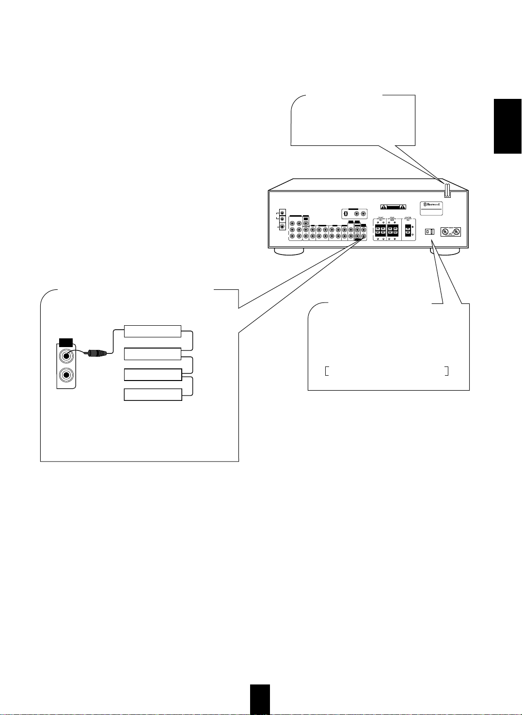
■ CONNECTING DIGITAL INPUTS
• The COAXIAL or the OPTICAL DIGITAL Out's of
the components that are connected to CD, VIDEO 2
and VIDEO 3 of this unit can be connected to these
DIGITAL INPUTS.
• A digital input should be connected to the components
such as a CD player, LD player, DVD player, etc. that
are capable of outputting a signal in the DTS, Dolby
Digital or PCM digital formats.
• For details, please refer to the operating instructions of
the component to be connected.
• When making COAXIAL DIGITAL connections use
75 Ohm Cable. Do not use standard audio patch cords.
• Not all of the commercially available Fiber Optic
cables are suitable for use with this receiver. If you
have a question as to the suitability of any cable,
please check with your dealer or a qualified service
organization.
• Remove the protective cap before making nay
OPTICAL connections. Reinsert the protective cap
when not using the OPTICAL Jacks.
• The speaker terminals are designed to accept either bare wire or
banana plugs.
• If using bare wire, take care to not allow the + and - wires to touch
or short.
• Connect the speaker wires firmly and correctly according to the
channel and position. Observe the proper polarity (+ and -).
• This receiver is designed for use with speakers rated at 6 ohms
impedance or above.
■ CONNECTING SPEAKERS
Front right
Front left
Rear left
Powered subwoofer
■
SUBWOOFER PRE OUT connection
• To emphasize the deep bass sound, connect a powered
subwoofer.
L
R
Rear right
Center
SUB
WOOFER
PRE OUT
OPTICAL
COAX 1 COAX 2
DIGITAL IN
Component with
COAXIAL DIGITAL OUT
Component with
COAXIAL DIGITAL OUT
Component with
OPTICAL DIGITAL OUT
MODEL NO. RD
-
7103
DIGITAL IN
EENNGGLLIISSHH
7
EENNGGLLIISSHHEENNGGLLIISSHH
Manufactured under license from Digital Theater Systems, Inc.
US Pat. No. 5,451,942 and other world-wide patents issues and pending.
“DTS” and “DTS Digital Surrou of Digital Theater Systems, Inc.
©1996 Digital Theater Systems, Inc. All rights reserved.
Manufactured under license from Dolby Laboratories. “Dolby”, “Pro Logic”
and the double-D symbol are trademarks of Dolby Laboratories. Confidential
Unpublished Works. ©1992-1997 Dolby Laboratories, Inc. All rights reserved.
AUDIO/VIDEO RECEIVER
MADE IN CHINA
DESIGNED IN USA
SWITCHED
120V~60Hz
100W 1A MAX
AC OUTLET
OPTICAL
COAX 1 COAX 2
AC INPUT
120V~60Hz
180W
SER. NO
This device complies with Part 15 of the FCC Rules.
Operation is subject to the following two conditions:
(1)This device may not cause harmful interference, and
(2)this device must accept any interference received,
including interference that may cause undesired operation.
CAUTION
RISK OF ELECTRIC SHOCK
DO NOT OPEN
WARNING:"SHOCK HAZARD-DO NOT OPEN"
AVIS;"RISQUE DE CHOC-ELECTRQUE-NE PAS OUVRIR"
AM
LOOP
FM
75
Ω
ANTENNA
AUX PLAY REC PLAY REC PLAY VIDEO 1
VIDEO 2
SUB
WOOFER
TAPE MON. VIDEO 1CDVIDEO 2
MONITOR
PRE OUT
VIDEO
OUT
DIGI
-LINK
VIDEO
IN
VIDEO 1
SUB
WOOFER
CENTER
FRONT REAR
L
R
6-CH DIRECT INPUT
L
R
■
AC INPUT CORD
Plug this cord into an AC
outlet.
CD player
Tape deck
Graphic equalizer
■ CONNECTING SYSTEM CONTROL
• Interconnect the GREEN system control jacks on
compatible Sherwood components that use the DIGI
LINK II or III system using standard RCA to RCA
cables.
DVD player
System
control
cord
Sherwood component
with DIGI LINK II or III
■
SWITCHED AC OUTLET
• This outlet is switched on(power-on mode)
and off(standby mode) according to power
controls as follows(Maximum total capacity
is 1A, 100W):
Standby mode – switched AC outlet off
Power-on mode – switched AC outlet on
DIGI
-LINK
MODEL NO. RD
-
7103
DIGITAL IN
EENNGGLLIISSHH
8
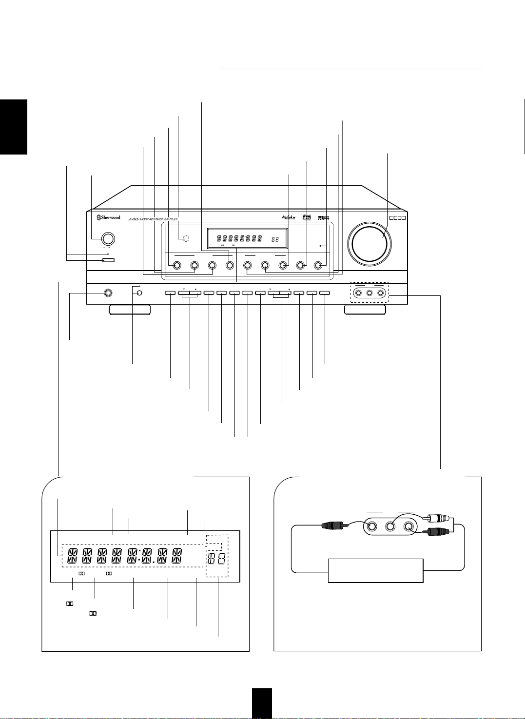
FFrroonntt PPaanneell CCoonnttrroollss
REMOTE
SENSOR
MASTER VOLUME
TONE
DIRECT
ON/STANDBY
MAIN POWER
STANDBY
ON/ OFF
TUNING/PRESETADJUST
PHONES
CHANNEL
SELECTOR
VIDEO L - AUDIO - R
VIDEO 3
BANDFM MODET/P MODETONE MODE
SPEAKER
MODE
DYNAMIC
RANGE
MEMO/ENTERCINEMA EQ
ON/OFF
SPEAKER
INPUT SELECTOR
AUDIO
VIDEO TAPE MON.
6CH DIRECT DSP MODEAUTO STEREO
DIGITAL
INPUTS
TONE
DIRECT
SURROUND MODE
TOTALLY DISCRETE AMPLIFIER STAGE
TDAS
ST TUNED TAPE M PRESET
Pro LogicDIGITAL
DTS
THEATER HALL SLEEP
dB
kHz
MHz
MEM
ms
INPUT, FREQUENCY, VOLUME LEVEL, OPERATING INFORMATION, etc.
STEREO INDICATOR
TUNED INDICATOR
DOLBY( ) PRO LOGIC INDICATOR
PRESET NUMBER, SLEEP TIME, DELAY TIME DISPLAY
TAPE MONITOR INDICATOR
MEMORY INDICATOR
DOLBY( ) DIGITAL INDICATOR
DTS INDICATOR
■ FLUORESCENT DISPLAY ■
VIDEO 3 VIDEO/AUDIO INPUT JACKS
THEATER INDICATOR
HALL INDICATOR
OUT
OUT
Additional video component
The VIDEO 3 jacks may be also connected to an additional
video component such as a camcorder, an LD plyaer or a
video game player, etc.
●
SPEAKER BUTTON/INDICATOR
CHANNEL SLECTOR BUTTON
ADJUST UP/DOWN
( / ) BUTTONS
TONE MODE BUTTON
SPEAKER MODE BUTTON
DYNAMIC RANGE BUTTON
HEADPHONE
JACK
STANDBY BUTTON/
INDICATOR
POWER SWITCH
VIDEO INPUT SELECTOR BUTTON
AUDIO INPUT SELECTOR BUTTON
TAPE MONITOR BUTTON
DIGITAL INPUT BUTTON
TONE DIRECT BUTTON/INDICATOR
MASTER VOLUME
CONTROL KNOB
CINEMA EQ BUTTON
MEMORY/ENTER BUTTON
TUNING/PRESET UP/DOWN
( / ) BUTTONS
REMOTE SENSOR
6 CH DIRECT BUTTON
STEREO BUTTON
AUTO BUTTON
DSP MODE BUTTON
▲ ▼
ST TUNED TAPE M PRESET
Pro LogicDIGITAL
DTS
THEATER HALL SLEEP
dB
kHz
MHz
MEM
ms
BAND BUTTON
TUNING/PRESET MODE BUTTON
FM MODE BUTTON
▲ ▼
VIDEO L - AUDIO - R
VIDEO 3
 Loading...