


® REGULATORS
|
|
® |
® |
(SRB3300) |
® |
|
Includes
®
(SRB3200)
Assembly & Maintenance Guide
FIRST STAGE - MAGNUM®II SRB3300, BLIZZARD® SRB3200, OASIS® SRB3400
NOTE: The Oasis®+ SRB3500 uses the SRB3601 externally adjustable first stage. The parts breakdown and servicing of the SRB3601 is covered in the Oasis2/Blizzard Assembly & Maintenance Guide. Oasis®+ regulators manufactured in 1990 have the SRB3801 first stage with the DSS feature. The servicing of the SRB3801 first stage is covered in the
Ultima SRB3800 Assembly & Maintenance Guide. To determine the first stage of a particular regulator, compare the regulator with the pictures and diagrams in this guide as well as the other guides referenced above. For further information, contact your authorized Sherwood Distributor.
ITEM # |
CATALOG # |
DESCRIPTION |
|
SRB3305 ........ |
First Stage Complete |
1 .................... |
3701-70 ...... |
Handwheel |
2 ...................... |
3504-6 ........ |
Star Washer Retainer |
3 ...................... |
1390-7 ........ |
Filter |
4................. |
29-3106-13A .... |
Moving Orifice |
|
|
(bare, no o-rings etc.) |
5 .................... |
3601-20 ...... |
Moving Orifice Assembly |
|
|
(with o-rings & washers) |
6................. |
19-8010-8 ........ |
Belleville Spring Washers (5 needed) |
7 .................... |
G007A .......... |
O-ring (2 needed) |
8 ............. |
MS28774-007 .... |
White Backup Washer |
9..................... |
5705-20 ...... |
Dust Cap |
10.................. |
1-1665-17 ...... |
Yoke Nut |
11 ................. |
2-3801-4.......... |
Yoke |
12 ................. |
2-3305-1 ........ |
Body |
13 ................... |
G904A ........ |
O-ring (for H. P. port plug) |
14 ................. |
1-3405-4 ........ |
H. P. Port Plug |
15 .................... |
3106-6 ........ |
One Way Bleed Valve |
16................... |
1-3105-6 ........ |
L. P. Port Plug |
17 .................... |
G011B ........ |
O-ring (for L. P. port plugs) |
18 .................... |
G122A ........ |
O-ring (seals cap to main body) |
19 ..................... |
3801-12B .... |
Main Spring |
20 .................. |
19-6526 .......... |
Shim (to raise hose pressure) |
21 .................... |
G007A ........ |
O-ring (for small end of piston) |
22 .................... |
3801-5 ........ |
Piston Seat |
23 .................... |
3107-10 ...... |
Piston Assembly |
|
|
(includes seat & O-rings) |
24 .................... |
G022A ........ |
O-ring (for large end of piston) |
25.................. |
2-3305-2 ........ |
Cap |
ORIFICE ASSEMBLY PARTS FOR BLIZZARD FIRST STAGE SRB3205
The following parts are the only parts that differentiate the Blizzard SRB3205 first stage from the standard Magnum II type SRB3305 first stage:
ITEM # |
CATALOG # |
DESCRIPTION |
B1 ...................... |
3504-6 ........ |
Larger Star Washer (holds orifice in body) |
B2 ............... |
J26005-43B ...... |
Smaller Star Washer (holds filter in orifice) |
B3 .................. |
18-3106-14 .... |
Filter |
B4 .................... |
G011B ........ |
O-ring (seals filter to orifice) |
B5 ............... |
29-3106-13 ...... |
Moving Orifice (bare, no O-rings etc.) |
B6 .................... |
3106-9 ........ |
Moving Orifice Assembly (with O-rings & |
B7 .............. |
64-8010-8 ........ |
Belleville Spring Washers (4 needed) |
TABLE OF CONTENTS
Page
1.0 Introduction . . . . . . . . . . . . . . . . . . . . . . . . . . . . . . . . . . . . .1
2.0 Specifications . . . . . . . . . . . . . . . . . . . . . . . . . . . . . . . . . . .3
2.1SRB3300 (Magnum II, SRB3400 (Oasis)
and SRB3500 (Oasis+) . . . . . . . . . . . . . . . . . . . . . . . . . . . . .3
3.0 O-ring Reference Chart . . . . . . . . . . . . . . . . . . . . . . . . . . . .4
4.0 First Stage Procedures . . . . . . . . . . . . . . . . . . . . . . . . . . . .5
4.1 Tools Required for First Stage Servicing . . . . . . . . . . . . . . . .5 4.2 Disassembly of First Stage . . . . . . . . . . . . . . . . . . . . . . . . . .5 4.3 Assembly of First Stage . . . . . . . . . . . . . . . . . . . . . . . . . . . .9 4.4 Testing of First Stage . . . . . . . . . . . . . . . . . . . . . . . . . . . . . . .10
5.0 Second Stage Procedures . . . . . . . . . . . . . . . . . . . . . . . . .12
5.1 Tools Required for Second Stage Servicing . . . . . . . . . . . . . .12 5.2 Disassembly of Second Stage . . . . . . . . . . . . . . . . . . . . . . . .12 5.3 Assembly of Second Stage . . . . . . . . . . . . . . . . . . . . . . . . . .14 5.4 Set-Up of Second Stage . . . . . . . . . . . . . . . . . . . . . . . . . . . .15 5.5 Testing of Second Stage . . . . . . . . . . . . . . . . . . . . . . . . . . . .17
6.0 Helpful Hints . . . . . . . . . . . . . . . . . . . . . . . . . . . . . . . . . . . .19
6.1 Troubleshooting Regulators . . . . . . . . . . . . . . . . . . . . . . . . . .19
6.2 Parts Cleaning Recommendations . . . . . . . . . . . . . . . . . . . . .21
6.3 Commonly Used Cleaning Solutions . . . . . . . . . . . . . . . . . . .21
6.4 Handling Tips . . . . . . . . . . . . . . . . . . . . . . . . . . . . . . . . . . . .22
7.0 Two Year Warranty and Maintenance Information . . . . . . .23
7.1 Proper Procedure for Warranty Paperwork . . . . . . . . . . . . . .23 7.2 Scheduled Maintenance . . . . . . . . . . . . . . . . . . . . . . . . . . . .23
BEFORE YOU BEGIN.....
READ THESE INSTRUCTIONS COMPLETELY BEFORE YOU BEGIN SERVICING THE REGULATOR.
THESE INSTRUCTIONS ARE INTENDED FOR PEOPLE WHO HAVE BEEN AUTHORIZED BY SHERWOOD TO REPAIR SHERWOOD SCUBA EQUIPMENT. IF YOU ARE NOT SO AUTHORIZED - STOP.
1.0 INTRODUCTION
1.The procedures in this manual apply to the Sherwood Scuba MAGNUM II (SRB3300),
OASIS (SRB3400), and OASIS+ (SRB3500).
The most current part numbers can be obtained by calling your Sherwood Sales Representative or Sherwood Scuba Customer Service.
WARNING
NEVER tighten the hose fitting to the first stage with more than 40 in. lbs. (4.5 Joules) of torque. The inlet hose fitting can be weakened by overtightening.
All current Sherwood Scuba Regulators have service kits available which contain the parts which must be changed at every annual service no matter what their condition. The standard annual service kit for the Oasis, Oasis+, and Magnum is 4000-15. All other parts not contained in this kit must be inspected by the technician and changed under warranty only if they have failed due to problems with material or workmanship.
NOTE: Oxygen Enriched Air conversion kits are available for all current Sherwood regulators and valves. The part number for the models covered in this manual is 4000-15N. These kits are to be installed into properly cleaned and prepared regulators only by technicians trained by one of the major oxygen enriched air training agencies.
2.This manual gives breakdowns of regulator parts, equipment specifications, servicing instructions, troubleshooting recommendations, and guidelines for proper care of these regulators. This manual is intended for use only by persons specially trained and authorized to service Sherwood Scuba equipment.
3.Anyone attempting to service or repair Sherwood Scuba regulators must have a thorough understanding of the principles of operation of scuba regulators and valves, as well as the appropriate mechanical ability. The technician must be properly trained in the safe use of compressed air and the various tools and cleaning solutions involved in the procedures outlined in this manual.
4.The best source for current part numbers for any of the parts listed in this manual is your current parts and price list from Sherwood.
5.Because of the many unique features found in Sherwood regulators, Sherwood conducts seminars on a regular basis throughout North America to train technicians in proper service and repair procedures for all current Sherwood regulators. In addition, all Sherwood dealers and their staff members are encouraged to attend the seminars to gain an in-depth understanding of the construction, special features and operation of Sherwood regulators. For information on the dates and locations of upcoming Sherwood service seminars near you, contact your Sherwood Sales Representative.
NOTE: You must be authorized by Sherwood to work on Sherwood Scuba equipment. You can obtain proper authorization by attending all appropriate seminars given in your area. This is the only way you can become an authorized Sherwood technician.
1

6.Companion instructional VHS videotapes to this and other Sherwood Scuba repair manuals are available from Sherwood Scuba at a nominal cost. Ask your Sherwood Scuba Sales Representative for details.
7.If you have any questions, or need more information, contact your Sherwood Scuba Sales Representative or Sherwood Distributor.
2

2.0SPECIFICATIONS
2.1SPECIFICATIONS FOR THE SRB3300 MAGNUM® II, SRB3400 & SRB3500 OASIS®
|
REGULATOR MODELS: |
Sherwood Magnum II SRB3300, |
|
|
Oasis SRB3400 & SRB3500 |
|
AIR FLOW: |
28-29 cu. ft. (793-821liters)/min. @ 1 atmosphere |
|
INHALATION RESISTANCE: |
1.1” (2.8 cm) w.c. @ 1 atmosphere |
|
EXHALATION RESISTANCE: |
0.8” (2 cm) w.c. max. @ 1 atm. |
|
RECOMMENDED LUBRICANT: |
LTI Christo-Lube® |
A. |
First Stage Regulator: |
|
|
TYPE: |
Flow-by piston with Moving Orifice Balancing and |
|
|
Dry Air Bleed - U.S. Pat. # 4,226,257 |
|
WEIGHT: |
1 lb. 3 oz. (.54kg) |
|
INTERSTAGE PRESSURE: |
135 -150 psi (9-10 bar) |
|
MAXIMUM INLET PRESSURE: |
232 Bar for SRB3300CE, SRB3900CE, |
|
|
SRB3400CE & SRB3500CE Models |
|
POSITIVE AIR PURGE |
|
|
FLOW RATE: |
13-27 cc/minute |
|
# LOW PRESSURE PORTS: |
4 (3/8”-24 UNF) |
|
# HIGH PRESSURE PORTS: |
2 (7/16”-20 UN) |
|
MATERIALS: |
Body - CDA-360 Brass |
|
|
O-rings - Buna-N |
|
|
Bleed Valve - Ethylene Propylene |
|
|
Piston Seat - Teflon® |
B. |
Second Stage Regulator: |
|
|
TYPE: |
Downstream valve, diaphragm, Variable Fulcrum |
|
|
- U.S. Pat. #3,991,785 |
|
WEIGHT: |
7.6 oz. (.22 kg) ( w/o hose) |
|
HOSE LENGTH: |
31 in. (.79 m) |
|
MATERIALS: |
Cover - Thermoplastic Vinyl |
|
|
Case - Thermoplastic Triax® |
|
|
Poppet Seat - Buna-N |
|
|
Poppet Seat - Buna-N |
|
|
O-Rings - Buna-N |
|
|
Diaphragm - Tufel® (black) |
|
|
Exhaust Valve - Thermoplastic Elastomer (blue) |
|
|
Mouthpiece - Liquid Silicone Rubber |
|
Maximum certified depth is 50m |
|
3

3.0 O-RINGS REFERENCE CHART
G907A
Seals second stage orifice
to case
G022A
Large End of piston
G122A
Seals cap to body
G007A
Moving orifice, small end of piston
G0101A
Outlet end of hose
G011B
L.P. port plug, inlet end of hose
G904A
Under filter in first stage H.P. port plug
1.Before you begin disassembly of the regulator, test the first and second stages for output pressures and leakage. Pre-testing in this way will help the technician to pinpoint any specific problems requiring repair.
2.The work area must be clean and well lighted, with clean compressed air available to blow sand and dirt from parts.
4
4.0FIRST STAGE PROCEDURES
4.1TOOLS REQUIRED FOR FIRST STAGE SERVICING
–Bench vise
–3/32" Allen wrench
–5/32" Allen wrench
–6" or 8" adjustable wrenches
–15" adjustable wrench
–Phillips screwdriver
–#10 Torx screwdriver
–Sherwood 50 cc Graduated Cylinder (p/n TL110)
–Sherwood Piston Seat Removal Tool (p/n TL112)
–Sherwood Plastic Probe (p/n TL111) to push out orifice
–Sherwood Regulator Support Handle (p/n TL113)
–Sherwood Intermediate Pressure Gauge (p/n TL119)
–Sherwood Inlet Filter Installation Tool (p/n TL115)
–Sherwood O-ring Installation Cones:
Brass-colored - p/n TL106 ( for installing small O-ring on piston tip )
Green-colored - p/n 38-TL107 ( for installing 1st O-ring onto moving orifice )
Black-colored - p/n 29-TL108 ( for installing 2nd O-ring onto moving orifice )
– Sherwood Oxygen Compatable Lubricant (Crystolube LTI) p/n SW-MS150
NOTE: For more information on Sherwood tools and their uses, see Sherwood’s Tools, Repair Kits and Accessories - Assembly & Maintenance Guide, available from Sherwood.
4.2DISASSEMBLY OF FIRST STAGE
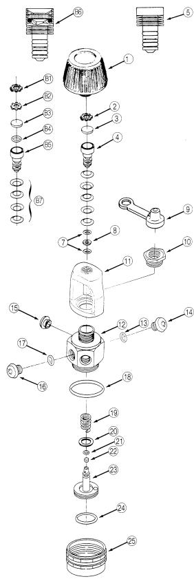
To view all the parts used in the first stage, fold out the front cover of this manual. The circled numbers below refer to the corresponding numbers on the drawing.
1.Use 6” or 8” adjustable wrenches to disconnect all hoses from the first stage. Pull back the hose protector from the inlet end of the hose. Inspect the hoses for wear. Pay particular attention to the area where the metal ferrules meet the rubber hose material. Replace hoses if necessary.
2.Unscrew and remove the handwheel 1 .
3.Remove the dust cap 9 .
5
4. |
Use a 5/32” Allen wrench, and a small adjustable wrench to remove all port plugs 14 16 and |
|
hoses from the body. |
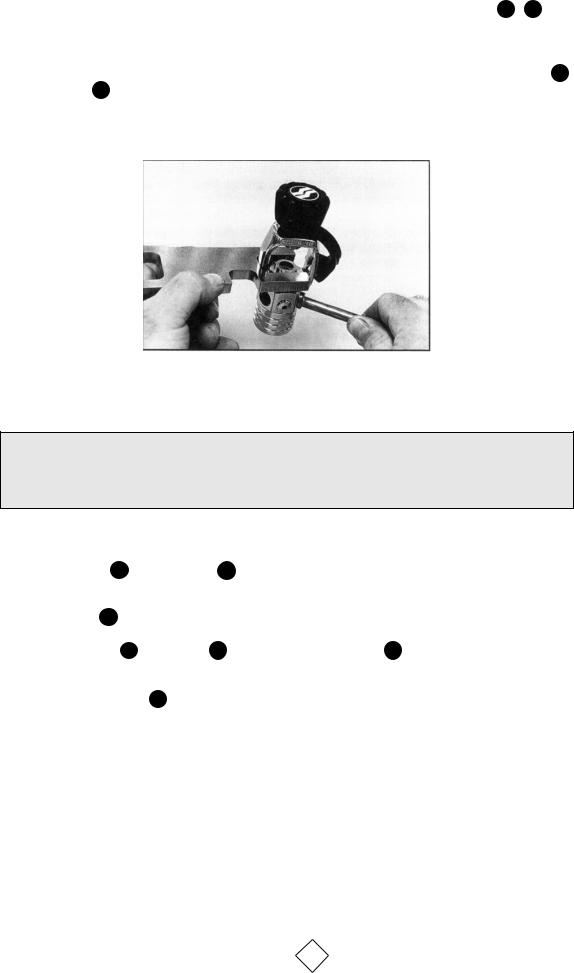
5.Install a Sherwood regulator support handle (p/n TL113) into one of the low-pressure ports. Use the support handle and a 15” adjustable wrench or bench vise to loosen the yoke nut 10 from the body 12 . See Photo #1.
Photo #1
NOTE: If a Sherwood DIN adapter (p/n SAA5200, or SAA5300) is installed in place of the more common yoke assembly, remove it at this time. See Sherwood Technical Bulletin #104 for servicing procedures for the DIN adapter.
6.Remove the yoke 11 and yoke nut 10 from the body.
7.Use the Sherwood regulator support handle and a 15” adjustable wrench or a bench vise to remove the cap 25 from the main body.
8.Remove the spring 19 any shims 20 and the piston assembly 23 from the cap. Remove both piston O-rings and discard them.
9.Remove the piston seat 22 by pushing through the stem with the Sherwood piston seat removal tool (p/n TL112) from the large end. The seat will then pop out. Discard the old seat.
6
 Loading...