


O P E R A T I N G I N S T R U C T I O N S
|
AUDIO/VIDEO RECEIVER R-956 |
|
|
|
|
|
|
|
|
|
|
T D A S |
||
|
|
|
|
|
|
|
|
|
|
MASTER VOLUME |
||||
MULTI CONTROL |
|
|
|
|
|
|
|
|
|
|
|
|
||
|
|
|
|
|
|
|
|
|
|
|
|
|
|
|
|
BAND AUTO/MANUAL |
|
|
|
|
|
|
|
CHECK |
CINEMA EQ |
|
|
||
|
|
MULT I ROOM |
|
|
|
|
|
|
|
|
|
|
|
|
|
|
REMOTE |
SENSOR |
|
|
|
|
|
|
|
|
|
|
|
|
TUNING/PRESET |
|
|
|
|
|
|
|
|
|
DYNAMIC |
|
|
|
|
MODE |
FM MODE |
|
|
|
|
|
|
|
ROOM2 FEED |
RANGE |
|
|
|
|
MAIN POWER |
|
|
INPUT SELECTOR |
|
|
SURROUND MODE |
|
|
|
|
|
||
|
|
STANDBY |
AUDIO |
VIDEO |
TAPE MON. |
6.1CH DIRECT |
AUTO |
DSP MODE |
STEREO |
DIGITAL/ANALOG |
|
|
||
|
|
|
|
|
|
|
|
|
|
|
|
|
||
|
|
ON/STANDBY |
|
|
|
|
|
|
|
|
|
|
|
|
|
ON / |
OFF |
|
|
|
|
|
|
|
|
|
|
|
|
PHONES |
CHANNEL |
|
SPEAKER |
|
|
|
|
|
|
|
|
|
VIDEO 5 |
|
SPEAKER |
|
|
|
|
|
|
|
|
|
|
|
|
||
SELECTOR |
TONE MODE |
MODE |
VIDEO LABEL |
MEMO/ENTER |
|
|
|
|
|
|
|
|
|
|
ON/OFF |
|
|
|
|
|
|
|
|
|
|
|
|
|
|
|
|
|
|
|
|
|
|
|
|
|
|
S-VIDEO |
VIDEO |
L - AUDIO - R |
R-956
AUDIO/VIDEO RECEIVER

ENGLISH
Introduction
U N P A C K I N G A N D

Congratulations on Your Purchase!
Your new high fidelity receiver is designed to deliver maximum enjoyment and years of trouble free service. Please take a few moments to read this manual thoroughly. It will explain the features and operation of your unit and help ensure a trouble free installation. Please unpack your unit carefully. We recommend that you save the carton and packing material. They will be helpful if you ever need to move your unit and may be required if you ever need to return it for service. Your unit is designed to be placed in a horizontal position and it is important to allow at least two inches of space behind your unit for adequate ventilation and cabling convenience.
To avoid damage, never place the unit near radiators, in front of heating vents, in direct sunlight, or in excessively humid or dusty locations. Connect your complementary components as illustrated in the following section.
CAUTION
RISK OF ELECTRIC SHOCK
DO NOT OPEN
CAUTION : TO REDUCE THE RISK OF
ELECTRIC SHOCK, DO NOT
REMOVE COVER (OR BACK).
NO USER-SERVICEABLE PARTS
INSIDE. REFER SERVICING TO
QUALIFIED SERVICE PERSONNEL.
This symbol is intended to alert the user to the presence of uninsulated "dangerous voltage" within the product's enclosure that may be of sufficient magnitude to constitute a risk of electric shock to persons.
This symbol is intended to alert the user to the presence of important operating and maintenance (servicing) instructions in the literature accompanying the appliance.
WARNING
To reduce the risk of fire or electric shock, do not expose this appliance to rain or moisture.
Caution : Do not block ventilation openings or stack other equipment on the top.
FOR U.S.A.
 Note to CATV System Installer: This reminder is provided to call the CATV system installer's attention to Article 820-40 of the NEC that provides guidelines for proper grounding and, in particular, specifies that the cable ground shall be connected to the grounding system of the building, as close to the point of cable entry as practical.
 FCC INFORMATION
This equipment has been tested and found to comply with the limits for a Class B digital device, pursuant to Part 15 of the FCC Rules. These limits are designed to provide reasonable protection against harmful interference in a residential installation. This equipment generates, uses and can radiate radio frequency energy and, if not installed and used in accordance with the instructions, may cause harmful interference to radio communications. However, there is no guarantee that interference will not occur in a particular installation. If this equipment does cause harmful interference to radio or television reception, which can be determined by turning the equipment off and on, the user is encouraged to try to correct the interference by one or more of the following measures:
 Reorient or relocate the receiving antenna.
 Increase the separation between the equipment and receiver.
 Connect the equipment into an outlet on a circuit different from that to which the receiver is connected.
 Consult the dealer or an experienced radio/TV technician for help.
CAUTION : Any changes or modifications in construction of this device which are not expressly approved by the party responsible for compliance could void the user's authority to operate the equipment.
Caution regarding placement (Except for U.S.A. and Canada)
To maintain proper ventilation, be sure to leave a space around the unit (from
the largest outer dimensions including projections) equal to, or greater than, shown below.
Left and right panels: 5 cm
Rear panel: 10 cm
Top panel: 20 cm
2
READ THIS BEFORE OPERATING 
FOR U.S.A. AND CANADA ...................................... |
120 V |
FOR YOUR SAFETY
Units shipped to the U.S.A. and Canada are designed for operation on 120 Volts AC only.
Observe all safety precautions for use of a polarized AC plug. However, some products may be supplied with a non polarized plug.
CAUTION: To prevent electric shock, match wide blade of plug to wide slot, insert fully.
FOR EUROPE AND AUSTRALIA .......... |
230 V/240 V |
FOR YOUR SAFETY
Units shipped to Australia are designed for operation on 240 V AC only.
To ensure safe operation, the three-pin plug supplied must be inserted only into a standard three-pin power point which is effectively earthed through the normal household wiring. Extension cords used with the equipment must be three-core and be correctly wired to provide connection to earth.
Improper extension cords are a major cause of fatalities. The fact that the equipment operates satisfactorily does not imply that the power point is earthed and that the installation is completely safe. For your safety, if in any doubt about the effective earthing of the power point, consult a qualified electrician.
PAN-EUROPEAN UNIFIED VOLTAGE
All units are suitable for use on supplies 230-240 V AC.
FOR OTHER COUNTRIES ........................... |
115 V/230 V |
FOR YOUR SAFETY
Units shipped to countries other than the above countries are equipped with an AC voltage selector switch on the rear panel. Refer to the following paragraph for the proper setting of this switch.
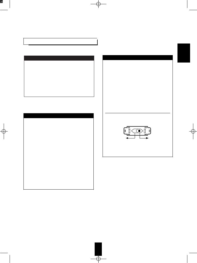
AC VOLTAGE SELECTION
This unit operates on 115/230 V AC. The AC voltage selector switch on the rear panel is set to the voltage that prevails in the area to which the unit is shipped. Before connecting the power cord to your AC outlet, make sure that the setting position of this switch matches your line voltage. If not, it must be set to your voltage in accordance with the following direction.
AC voltage selector switch
AC 230 V |
AC 115 V |
Move switch lever to match your line voltage with a
ENGLISH
3

ENGLISH
CONTENTS |
|
Introduction |
|
UNPACKING AND INSTALLATION....................................................................................................... |
2 |
READ THIS BEFORE OPERATING YOUR UNIT................................................................................... |
3 |
System Connections........................................................................................................................................ |
5 |
Front Panel Controls...................................................................................................................................... |
9 |
Universal Remote Control |
|
DIGI LINK SYSTEM REMOTE CONTROLS......................................................................................... |
10 |
OPERATING COMPONENTS WITH REMOTE CONTROL................................................................. |
12 |
REMOTE CONTROL OPERATION RANGE.......................................................................................... |
12 |
LOADING BATTERIES............................................................................................................................ |
12 |
ENTERING A SETUP CODE ................................................................................................................... |
13 |
Operations |
|
LISTENING TO A PROGRAM SOURCE................................................................................................ |
14 |
SURROUND SOUND................................................................................................................................ |
17 |
ENJOYING SURROUND SOUND........................................................................................................... |
19 |
LISTENING TO RADIO BROADCASTS................................................................................................ |
23 |
RECORDING............................................................................................................................................. |
26 |
DIGITAL AUDIO RECORDING WITH MD RECORDER..................................................................... |
27 |
MULTI SOURCE PLAYBACK ................................................................................................................ |
28 |
OTHER FUNCTIONS................................................................................................................................ |
29 |
Using the OSD |
|
CURRENT STATUS DISPLAY................................................................................................................ |
31 |
MENU SCREEN ........................................................................................................................................ |
31 |
Troubleshooting Guide ................................................................................................................................ |
33 |
Specifications.................................................................................................................................................. |
34 |
4
System Connections
 When making system connections, please be certain the AC cord is not plugged into an AC outlet.
 When making connections between components, please be sure to connect the white RCA plugs to the L (left) and the red RCA plugs to the R (right) jacks respectively.
 Change the position of the FM indoor antenna until you get the best possible reception of your favorite FM stations.
 A 75 Ohm outdoor FM antenna may be used to further improve the reception. Disconnect the indoor antenna before connecting the outdoor antenna.
 Place the AM loop antenna as far as possible from the receiver, TV set, speaker cords and the AC input cord and set it to a direction for the best reception.
 If the reception is poor with the AM loop antenna, an AM outdoor antenna can be used in place of the AM loop antenna.
 Make all connections firmly and correctly. Failure to do so can cause loss of sound, noise or damage to the receiver.
 If the electricity fails or the AC cord is left unplugged for about two weeks, all operating parameters in the unit’s memory will be lost. Should this happen, you must enter them again.
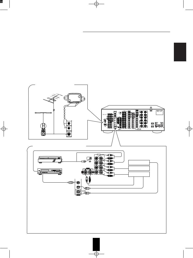
■ CONNECTING ANTENNAS
FM
(OUTDOOR ANTENNA)
FM
(INDOOR ANTENNA) |
AM loop antenna |
IN |
VIDEO |
Y |
|
|
|
|
DIGITAL |
GND |
OUT |
|
|
|
|
|
IN |
|
|
|
AC INPUT |
MODEL NO. R-956 |
|
|
|
PHONO |
S-VIDEO |
CB |
|
||
|
L R |
|
OUT |
|
FRONT |
4A |
AUDIO/VIDEO RECEIVER |
|
|
VIDEO 3 |
|
|
(8Ω) |
|
MADE IN KOREA |
|
“ |
|
|
|
|
|
DESIGNED IN USA |
|
CD |
|
CR |
|
|
SER. NO |
|
|
is a trademark |
|
|
|
|
|
of SRS Labs, |
|
|
VIDEO 4 |
|
|
|
MONITOR |
R |
L |
|
Inc.” |
REAR |
COXIAL |
|
AUX |
|
|
Y |
|
|
|
|
|
|
|
OUT |
|
|
|
|
Manufactured under license from Dolby Laboratories.“Dolby”,“Pro Logic” |
|
|
|
VIDEO 1 |
L |
R |
|
|
|
|
and the double-D symbol are trademarks of Dolby Laboratories. |
|
|
|
|
|
TAPE |
6.1 CH |
6.1 CH |
CB |
REAR |
Confidential Unpublished Works. ©1992-1997 Dolby Laboratories, Inc. |
|
|
|
|
|
MON. |
SPEAKERS |
All rights reserved. |
|
|||
|
|
VIDEO 2 |
|
|
|
|
|
(8Ω) |
Manufactured under license from Digital Theater Systems, Inc. |
|
AM |
|
|
|
|
|
|
|
|
US Pat. No. 5,451,942 and other world-wide patents issues and pending. |
|
LOOP |
|
|
|
VIDEO 1 |
VIDEO 1 |
VIDEO 1 |
CR |
|
“DTS” and “DTS Digital Surrou emarks of Digital Theater |
|
|
|
|
|
|
Systems, Inc. ©1996 Digital Theater Systems, Inc. All rights reserved. |
|||||
|
|
CD |
|
|
|
|
VIDEO 2 |
R |
L |
|
300 ohm |
|
|
|
|
|
|
AC OUTLETS |
E 8 5 6 4 9 |
||
|
|
|
VIDEO 2 |
VIDEO 2 |
VIDEO 2 |
Y |
|
|
29Z3 |
|
|
|
|
|
|
LISTED |
|||||
feeder |
|
|
|
|
|
|
|
CENTER |
CENTER |
C |
|
|
TAPE/MD |
|
|
|
|
|
REAR |
FRONT |
|
AM |
|
|
|
VIDEO 3 |
VIDEO 3 |
VIDEO 3 |
CB |
SPEAKER |
SPEAKER |
|
|
|
|
|
|
|
|
(8Ω) |
(8Ω) |
|
|
LOOP |
|
|
OPTICAL |
|
|
|
|
|
|
|
|
|
|
|
VIDEO 4 |
VIDEO 4 |
VIDEO 4 |
CR |
|
|
|
ANTENNA |
|
|
|
|
|
|
|
|
SWITCHED |
|
■ CONNECTING AUDIO COMPONENTS
Tumtable with MM type cartridge |
|
|
|
IN |
|
|
|
|
GND |
|
|
|
|
|
|
|
|
PHONO |
|
|
|
|
|
|
CD |
|
Additional MD recorder |
|
|
|
|
|
for digital recording |
|
|
|
|
|
|
|
|
CD player |
|
OUT |
|
AUX |
|
Additional |
|
|
|
|
|
audio component |
|
|
L |
R |
|
|
|
|
|
TAPE |
|
REC |
TAPE |
PLAY(LINE OUT) |
Tape deck or |
|
MON. |
|
MON. |
|||
|
|
|
|
|
||
|
|
|
|
|
|
MD recorder |
OPTICAL OUT |
CD |
|
|
|
|
|
|
|
|
|
|
REC(LINE IN) |
|
|
TAPE/MD |
|
|
|
|
|
|
|
|
|
|
OPTICAL OUT |
|
|
OPTICAL |
|
|
|
OPTICAL IN |
|
|
|
|
|
|
|
|
|
OUT |
|
|
|
|
|
•The AUX jacks may be connected to an additional audio component such as a CD player, a tape deck, etc.
•Connect the TAPE MONITOR IN/OUT jacks to the PLAY(LINE OUT)/REC(LINE IN) jacks of a tape deck or MD recorder.
•The TAPE MONITOR IN/OUT jacks may also be connected to the LINE OUT/IN jacks of an optional graphic equalizer.
•If a digital recorder or other component with OPTICAL DIGITAL IN/OUT jacks is connected to the corresponding jacks of this unit,
you can playback and/or record the high quality sound of CD’s, etc. without analog conversion or degradation. ■Notes:
•The phono input of your receiver is not suitable for the direct connection of a turntable with a Moving Coil (MC) cartridge. If you have a MC cartridge, use a separate head amplifier of step-up transformer between the turntable and the receiver.
•Not all of the commercially available Fiber Optic cables are suitable for use with this receiver. If you have a question as to the suitability of any cable, please check with your dealer or a qualified service organization.
•Remove the protective cap before making any OPTICAL connections. Re-insert the protective cap when not using the OPTICAL jacks.
ENGLISH
5
ENGLISH
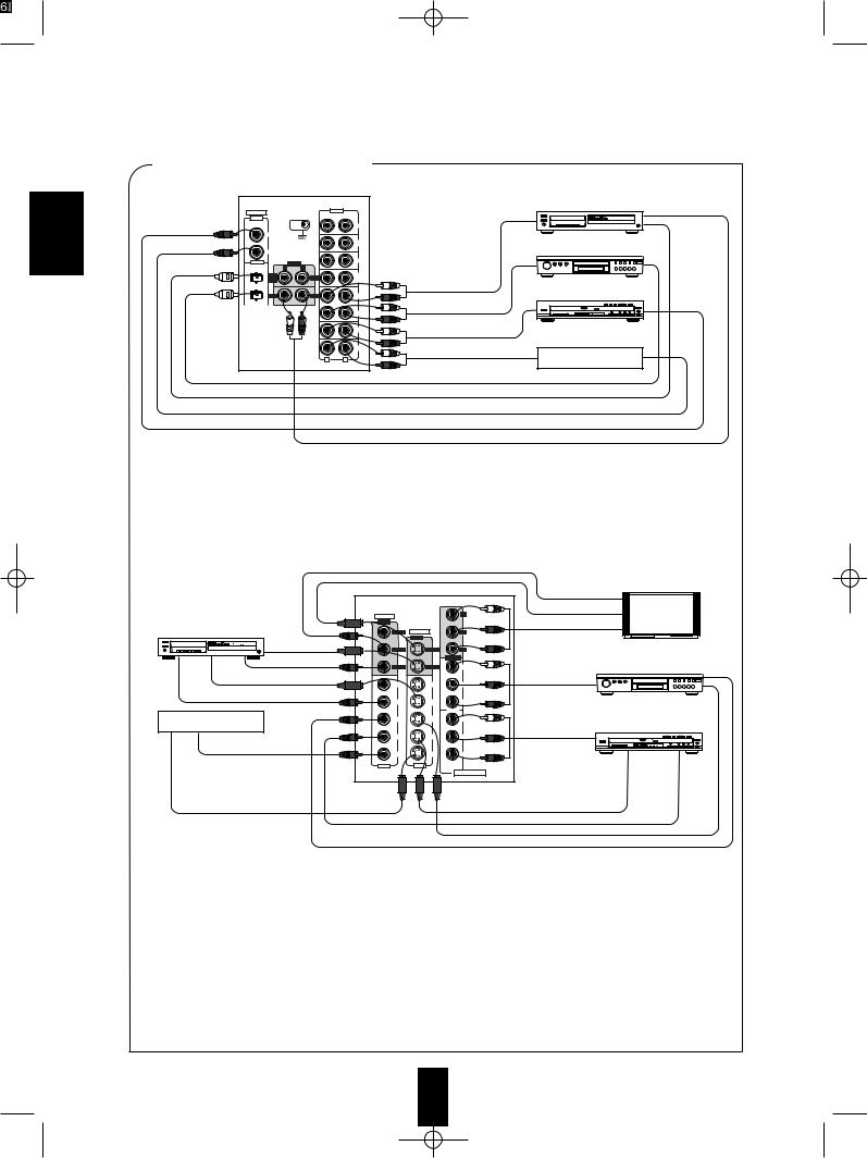
■ CONNECTING VIDEO COMPONENTS |
|||
This unit |
|
|
|
|
|
|
Video deck |
DIGITAL |
|
|
IN |
IN |
|
|
|
|
|
|
PHONO |
VIDEO 3 |
|
|
|
|
|
|
CD |
VIDEO 4 |
|
|
DVD player |
COXIAL |
|
OUT |
AUX |
|
|
|
|
VIDEO 1 |
L |
R |
|
TAPE |
|
REC |
TAPE |
MON. |
|
MON. |
|
|
|
||
VIDEO 2 |
AUDIO PLAY(OUT) |
VIDEO 1 |
REC |
VIDEO 1 |
LD player |
|
VIDEO 2 |
AUDIO OUT |
5 DISC |
|
|
|
|
||
|
VIDEO 3 |
AUDIO OUT |
|
|
|
VIDEO 4 |
AUDIO OUT |
TV or additional |
|
L |
R |
|||
|
video component |
|||
|
|
|
||
|
|
|
OPTICAL OUT |
|
|
|
|
OPTICAL OUT |
|
|
|
|
COXIAL OUT |
|
|
|
|
COXIAL OUT |
|
|
|
|
AUDIO REC (IN) |
• This receiver has two kinds of digital jacks (OPTICAL, COAXIAL), three kinds of video jacks (COMPONENT, S-VIDEO, and COMPOSITE) as well as analog audio jacks for making connections with your video equipment. Depending on the capabilities of your video components, hook them up to the corresponding input/output jacks for VIDEO 1 to 4 respectively.
■Notes:
•When making COAXIAL DIGITAL connections use 75 Ohm Cable. Do not use standard audio patch cords.
•Not all of the commercially available Fiber Optic cables are suitable for use with this receiver. If you have a question as to the suitability of any cable, please check with your dealer or a qualified service organization.
•Remove the protective cap before making any OPTICAL connections. Re-insert the protective cap when not using the OPTICAL Jacks.
This unit |
|
COMPOSITE VIDEO IN |
Monitor TV |
|
|
|
|
|
Green |
S-VIDEO IN |
|
|
Y |
|
|
VIDEO |
|
|
|
OUT |
Blue |
COMPONENT VIDEO IN |
|
|
|
|
Video deck |
ROOM 2 S-VIDEO |
CB |
|
|
OUT |
|
Red |
|
S-VIDEO IN |
|
|
|
|
|
MONITOR |
MONITOR |
CR |
Green |
|
|
COMPOSITE VIDEO IN |
|
MONITOR |
|
|
|
VIDEO 1 |
VIDEO 1 |
Y |
|
DVD player |
|
|
|
||||
S-VIDEO OUT |
|
|
|
Blue |
COMPONENT |
6.1 CH |
6.1 CH |
CB |
|
||
|
|
VIDEO OUT |
|||
|
|
|
|
|
COMPOSITE VIDEO OUT |
VIDEO 1 |
VIDEO 1 |
|
Red |
|
|
|
|
CR |
|
|
||
|
|
|
VIDEO 2 |
|
|
|
TV or additional |
VIDEO 2 |
VIDEO 2 |
|
Y |
|
LD player |
video component |
|
|
|
Green |
COMPONENT |
|
|
VIDEO 3 |
VIDEO 3 |
|
CB |
|
|
|
|
VIDEO OUT |
|
|||
|
|
|
|
Blue |
5 DISC |
|
COMPOSITE VIDEO OUT |
|
|
|
|
|
|
VIDEO 4 |
VIDEO 4 |
|
CR |
|
|
|
|
|
|
|
|||
|
IN |
IN |
VIDEO 3 |
Red |
|
|
|
|
|
|
|||
|
|
|
COMPONENT |
|
|
|
S-VIDEO OUT |
|
|
|
|
S-VIDEO OUT |
|
|
|
|
|
|
COMPOSITE VIDEO OUT |
|
S-VIDEO OUT
COMPOSITE VIDEO OUT
•This unit incorporates COMPONENT as well as S and composite(normal) VIDEO jacks.
•For your reference, the excellence in picture quality is as follows: “COMPONENT” > “S” > “COMPOSITE”.
•When making COMPONENT VIDEO connections, connect “Y” to “Y”, “CB” to “CB” (or “B-Y”, “PB”) and “CR” to “CR”(or “R-Y”, “PR”).
•Signals inputted into the COMPONENT VIDEO IN jacks will be outputted in only the MONITOR COMPONENT VIDEO OUT jacks.
•A signal inputted into the composite(normal) VIDEO IN jack will be outputted in the composite(normal) VIDEO OUT jacks. However, in case of S-VIDEO signal, a signal inputted into the S-VIDEO IN jack will be outputted in the S-VIDEO OUT jacks and the
MONITOR composite(normal) VIDEO OUT jack besides. ■Notes
•The on-screen display function and recording the component video signals are not available when using the COMPONENT VIDEO connections.
•When Sherwood DVD player such as V-756, etc. is connected to the DIGI LINK jack for system control, you should connect the DVD player to the "VIDEO 2" jacks of this unit.
Because, if the PLAY button, etc. is pressed on the DVD player, the VIDEO 2 is automatically selected as an input source on this unit and the playback, etc. starts.
6
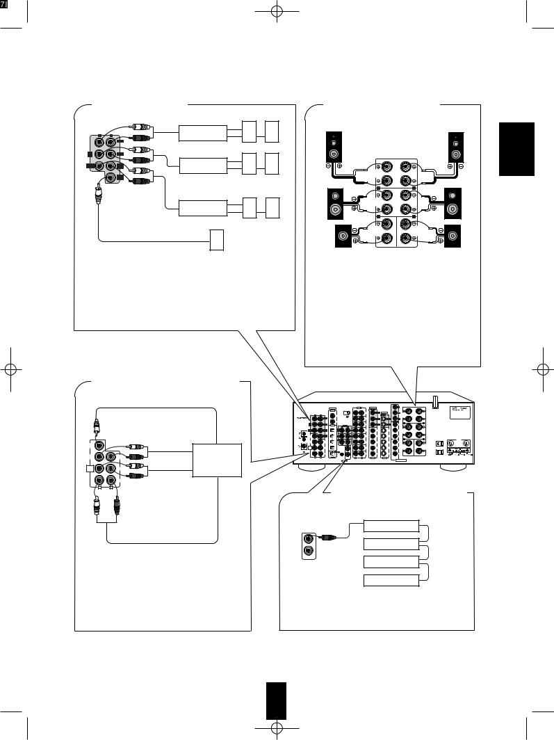
■ PRE OUT connections |
■ CONNECTING SPEAKERS |
L |
R |
Power amplifier |
|
|
FRONT |
|
|
|
|
Front speakers |
|
PRE |
REAR |
|
|
OUT |
|
|
|
CENTER |
CENTER |
Power amplifier |
|
FRONT |
REAR |
|
|
|
SUB |
Rear speakers |
|
|
WOOFER |
||
|
|
Power amplifier |
|
|
|
Front center |
Rear center |
|
|
speaker |
speaker |
Powered subwoofer
•Use these jacks when adding additional amplifiers.
•Connect the PRE OUT jacks to the powered speakers or the power amplifiers connected to speakers respectively.
•To emphasize the deep bass sounds, connect a powered subwoofer.
•Only in case of enjoying 6.1 channels of digital audio, make the rear center connections between the audio equipment.
■ CONNECTING 6.1 CH DIRECT INPUTS
|
Front right |
|
Front left |
|
FRONT |
|
|
|
SPEAKERS |
|
|
|
(8Ω) |
|
|
|
R |
L |
|
Rear |
REAR |
|
|
SPEAKERS |
|
|
|
right |
(8Ω) |
|
Rear |
|
|
||
|
R |
L |
left |
|
|
||
|
REAR |
FRONT |
|
Rear |
CENTER |
CENTER |
Front |
SPEAKER |
SPEAKER |
||
(8Ω) |
(8Ω) |
||
center |
|
|
center |
•The speaker terminals are designed to accept either bare wire or banana plugs.
•If using bare wire, take care to not allow the + and - wires to touch or short.
•Connect the speaker wires firmly and correctly according to the channel and position. Observe the proper polarity (+ and -).
•To reproduce the center rear signal in 6.1 channel material, connect a rear center speaker. Otherwise the center rear speaker is not necessary.
•This receiver is designed for use with speakers rated at 8 ohms impedance or above.
SUBWOOFER CH OUT
SUB |
|
|
WOOFER |
|
CENTER CH OUT |
|
|
|
FRONT |
REAR |
6.1 CH decoder |
CENTER |
CENTER |
|
DIRECT |
REAR |
REAR CH OUT |
6.1-CH |
|
|
INPUT |
|
|
|
FRONT |
|
L |
R |
|
FRONT CH OUT
•Use these jacks to connect the corresponding analog outputs of an external 6.1(or 5.1) channel decoder or to a DVD player with 6.1(or 5.1) channel outputs.
•In the case of a 5.1 channel decoder or DVD player, do not make a connection to the rear center input. (For more details, please see the operator's manual of the component to be connected.)
|
|
IN |
VIDEO |
Y |
|
|
|
|
DIGITAL |
GND |
OUT |
|
|
|
|
|
IN |
|
|
|
AC INPUT |
MODEL NO. R-956 |
|
|
|
PHONO |
S-VIDEO |
CB |
FRONT |
120V~60Hz |
|
L |
R |
VIDEO 3 |
OUT |
|
SPEAKERS |
|
|
|
|
|
|
(8Ω) |
|
MADE IN KOREA |
|
|
|
|
|
|
|
|
DESIGNED IN USA |
|
|
CD |
|
CR |
|
|
SER. NO |
|
|
VIDEO 4 |
|
|
|
MONITOR |
R |
L |
REAR |
COXIAL |
|
AUX |
|
|
Y |
|
|
|
|
|
OUT |
|
|
|
|
Manufactured under license from Dolby Laboratories.“Dolby”,“Pro Logic” |
|
VIDEO 1 |
L |
R |
|
|
|
|
and the double-D symbol are trademarks of Dolby Laboratories. |
|
|
|
TAPE |
6.1 CH |
6.1 CH |
CB |
REAR |
Confidential Unpublished Works. ©1992-1997 Dolby Laboratories, Inc. |
|
|
|
MON. |
SPEAKERS |
All rights reserved. |
|||
|
VIDEO 2 |
|
|
|
|
|
(8Ω) |
Manufactured under license from Digital Theater Systems, Inc. |
|
|
|
|
|
|
|
|
US Pat. No. 5,451,942 and other world-wide patents issues and pending. |
|
|
|
VIDEO 1 |
VIDEO 1 |
VIDEO 1 |
CR |
|
“DTS” and “DTS Digital Surrou emarks of Digital Theater |
|
|
|
|
Systems, Inc. ©1996 Digital Theater Systems, Inc. All rights reserved. |
CD |
|
|
VIDEO 2 |
R |
L |
|
|
|
|
AC OUTLETS |
E 8 5 6 4 9 |
||
VIDEO 2 |
VIDEO 2 |
VIDEO 2 |
Y |
|
|
29Z3 |
|
|
LISTED |
||||
|
|
|
|
|
|
AUDIO EQUIPMENT |
TAPE/MD |
|
|
|
REAR |
FRONT |
C |
|
|
|
|
CENTER |
CENTER |
|
VIDEO 3 |
VIDEO 3 |
VIDEO 3 |
CB |
SPEAKER |
SPEAKER |
|
(8Ω) |
(8Ω) |
|
|
|
|
OPTICAL |
|
|
|
|
|
|
|
|
|
|
|
VIDEO 4 |
VIDEO 4 |
VIDEO 4 |
|
CR |
L |
R |
|
|
|
|
|
|
VIDEO 3 |
SWITCHED |
OUT |
DIGI-LINK |
L |
R |
IN |
IN |
120V~60Hz |
|||
|
|
|
TOTAL 100W 1A MAX |
■ CONNECTING SYSTEM CONTROL
Sherwood component with DIGI LINK II or III
CD player
System
Tape deck control cord
DIGI-LINK
Graphic equalizer
DVD player
•Connect this jack to the DIGI LINK jack of the external Sherwood component that uses the DIGI LINK II or III remote control system.
ENGLISH
7
ENGLISH
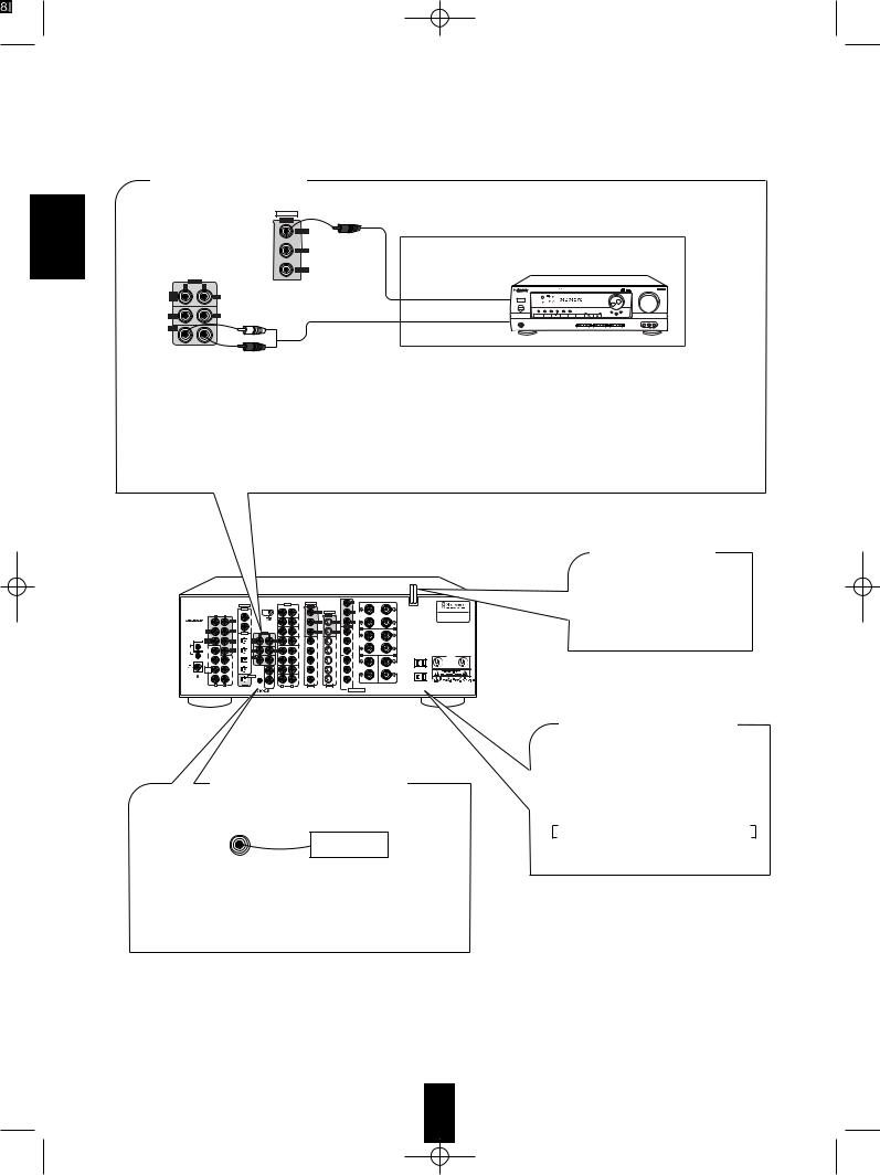
■ ROOM 2 connections
VIDEO
|
OUT |
Another room |
|
|
ROOM 2 |
|
|
|
MONITOR |
|
|
|
VIDEO 1 |
|
A/V receiver or integrated amplifier |
|
OUT |
|
|
L |
R |
COMPOSITE VIDEO IN |
|
|
|
T D A S |
|
TAPE |
REC |
|
|
MON. |
|
|
|
|
|
|
|
VIDEO 1 |
REC |
AUDIO IN |
|
ROOM2 |
|
|
|
•If another A/V receiver or integrated amplifier, etc. is connected to these jacks, you can play a different program source in another room as well as one source in the main room at the same time.(For details, refer to “MULTI SOURCE PLAYBACK” on page 28).
•When the multiroom adaptor is connected, the ROOM 2 functions is more convenient.
■Note:
• Use high quality connection cords in such a way that there is no humming or noise.
|
|
COXIAL |
|
OUT |
|
|
|
|
|
Manufactured under |
|
|
|
|
|
|
|
|
|
|
|
||
|
|
VIDEO 1 |
L |
R |
|
|
|
|
|
and the double-D |
|
FRONT |
|
|
|
|
TAPE |
6.1 CH |
6.1 CH |
CB |
REAR |
Confidential Unpublished |
|
CENTER |
|
|
|
REC |
MON. |
SPEAKERS |
All rights reserved. |
|
|||
|
|
VIDEO 2 |
|
|
|
|
|
|
(8Ω) |
Manufactured under |
|
AM |
|
|
|
|
|
|
|
|
|
US Pat. No. 5,451,942 |
|
LOOP |
|
|
|
REC |
VIDEO 1 |
VIDEO 1 |
VIDEO 1 |
CR |
|
“DTS” and “DTS Digital |
|
W |
|
|
|
|
|
|
|
|
|
Systems, Inc. ©1996 Digital Theater Systems, Inc. All rights reserved. |
|
|
|
CD |
|
|
|
|
VIDEO 2 |
|
R |
L |
|
|
|
|
|
|
|
|
|
AC OUTLETS |
E 8 5 649 |
||
FRONT |
|
REAR |
|
|
VIDEO 2 |
VIDEO 2 |
VIDEO 2 |
Y |
|
|
29Z3 |
CENTER |
|
CENTER |
|
|
|
|
LISTED |
||||
|
|
|
|
|
|
|
|
|
AUDIO EQUIPMENT |
||
|
|
TAPE/MD |
|
|
|
|
|
|
REAR |
FRONT |
C |
6.1-CH |
|
|
|
|
|
|
|
|
CENTER |
CENTER |
|
DIRECT |
|
REAR |
|
|
VIDEO 3 |
VIDEO 3 |
VIDEO 3 |
CB |
SPEAKER |
SPEAKER |
|
INPUT |
|
|
|
|
(8Ω) |
(8Ω) |
|
||||
|
|
|
OPTICAL |
|
|
|
|
|
|
|
|
|
|
FRONT |
|
|
VIDEO 4 |
VIDEO 4 |
VIDEO 4 |
CR |
|
|
|
ANTENNA |
|
|
|
|
|
|
|
|
|
SWITCHED |
|
L |
R |
|
|
L |
R |
IN |
VIDEO 3 |
|
|
|
|
OUT |
|
IN |
|
|
120V~60Hz |
|
|||||
■ AC INPUT CORD
Plug this cord into a wall AC outlet.
■CONNECTING MULTIROOM ADAPTOR
Adaptor
OUT
MULTIROOM
•To control this component from a remote location, connect this jack to the output of the multi-room adaptor.
For information on the multi-room adaptor, contact the Xantech corporation at 1-800-843-5465.
■SWITCHED AC OUTLETS
•These outlets are switched on(power-on mode) and off(standby mode) according to power control as follows(Maximum total capacity is 1A, 100W):
Standby mode – switched AC outlet off Power-on mode – switched AC outlet on
8

Front Panel Controls
AUTO/MANUAL BUTTON MULTI ROOM |
CHECK BUTTON |
CINEMA EQ BUTTON |
|
BAND BUTTON |
REMOTE SENSOR |
||
|
|
|
|
TUNING/PRESET MODE BUTTON |
ROOM 2 FEED BUTTON |
DYNAMIC RANGE BUTTON |
|
|
|
|
|
FM MODE BUTTON |
|
|
MASTER VOLUME |
|
|
CONTROL KNOB |
|
|
|
|
|
MULTI CONTROL KNOB
AUDIO/VIDEO RECEIVER R-956 |
|
T D A S |
|
|
MASTER VOLUME |
||
MULTI CONTROL |
|
|
|
|
|
|
|
BAND |
AUTO/MANUAL |
CHECK |
CINEMA EQ |
|
MULT I ROOM |
|
|
|
REMOTE SENSOR |
|
|
TUNING/PRESET |
ROOM2 FEED |
DYNAMIC |
|
MODE |
FM MODE |
RANGE |
|
|
MAIN POWER |
|
|
INPUT SELECTOR |
|
SURROUND MODE |
|
|
|
||
|
|
STANDBY |
|
AUDIO |
VIDEO |
TAPE MON. 6.1CH DIRECT |
AUTO |
DSP MODE |
STEREO DIGITAL/ANALOG |
|
|
|
|
|
|
|
|
|
|
|
|
|
|
|
|
ON/STANDBY |
|
|
|
|
|
|
|
|
|
|
ON / |
OFF |
|
|
|
|
|
|
|
|
|
PHONES |
CHANNEL |
|
SPEAKER |
|
|
|
|
|
|
VIDEO 5 |
|
SPEAKER |
TONE MODE |
VIDEO LABEL |
MEMO/ENTER |
|
|
|
|
|
|
||
SELECTOR |
MODE |
|
|
|
|
|
|
||||
ON/OFF |
|
|
|
|
|
|
|
|
|
|
|
|
|
|
|
|
|
|
|
|
S-VIDEO |
VIDEO |
L - AUDIO - R |
|
DIGITAL/ANALOG BUTTON |
|
HEADPHONE JACK |
STEREO BUTTON |
|
SPEAKER BUTTON |
DSP MODE BUTTON |
|
|
||
POWER SWITCH |
AUTO BUTTON |
|
6.1 CHANNEL DIRECT BUTTON |
||
|
||
CHANNEL SELECTOR BUTTON |
TAPE MONITOR BUTTON |
|
|
||
TONE MODE BUTTON |
MEMORY/ENTER BUTTON |
|
STANDBY BUTTON/INDICATOR |
VIDEO SELECTOR BUTTON |
|
|
||
SPEAKER MODE BUTTON |
VIDEO LABEL BUTTON |
|
AUDIO SELECTOR BUTTON |
||
|
■ FLUORESCENT DISPLAY
|
|
|
|
|
|
|
TUNED INDICATOR |
|||||||||||||||
|
|
|
|
|
|
|
|
STEREO INDICATOR |
||||||||||||||
VIDEO INPUT INDICATORS |
|
|
|
TONE DIRECT INDICATOR |
||||||||||||||||||
|
|
|
|
|
|
|
|
|
|
|||||||||||||
|
|
SURROUND MODE |
|
|
|
|
AUTO INDICATOR |
|||||||||||||||
|
|
INDICATORS |
|
|
|
|
|
MEMORY INDICATOR |
||||||||||||||
|
|
|
|
|
|
|||||||||||||||||
|
|
|
|
|
TAPE MONITOR |
|
|
|
|
|
||||||||||||
|
|
|
|
|
|
|
|
|
|
|
PRESET INDICATOR |
|||||||||||
|
|
|
|
|
INDICATOR |
|
|
|
|
|
|
|||||||||||
|
|
|
|
|
|
|
|
|
|
|
|
|
CHANNEL |
|||||||||
|
|
|
|
|
|
|
|
|
|
|
|
|
|
|
||||||||
|
|
|
|
|
|
|
|
|
|
|
|
|
|
|
INDICATORS |
|||||||
|
|
|
|
|
|
|
|
|
|
|
|
|
|
|
|
|
|
|
|
|
|
|
|
|
|
|
|
|
|
|
|
|
|
|
|
|
|
|
|
|
|
|
|
|
|
|
|
|
|
|
|
|
|
|
|
|
|
|
|
|
|
|
|
|
|
|
|
|
|
|
|
|
|
|
|
|
|
|
|
|
|
|
|
|
|
|
|
|
|
|
|
|
|
|
|
|
|
|
|
|
|
|
|
|
|
|
|
|
|
|
|
|
|
|
|
|
|
|
|
|
|
|
|
|
|
|
|
|
|
|
|
|
|
|
|
|
|
|
|
|
|
|
|
|
|
|
|
|
|
|
|
|
|
|
|
|
|
|
|
|
|
|
|
|
|
|
|
|
|
|
|
|
|
|
|
|
|
|
|
|
|
|
|
|
|
|
|
|
|
|
|
|
|
|
|
|
|
|
|
|
|
|
|
|
|
|
|
|
|
|
|
|
|
|
|
|
|
|
|
|
|
|
|
|
|
|
|
|
|
DIGITAL/ANALOG INDICATORS |
SPEAKER INDICATOR |
SLEEP INDICATOR MUTE INDICATOR
INPUT, FREQUENCY, VOLUME LEVEL, OPERATING INFORMATIONS, etc.
■ VIDEO 5 INPUT JACKS
Additional video component
S-VIDEO OUT
AUDIO OUT
VIDEO OUT
•The front VIDEO 5 input jacks may be also connected to an additional video component such as a camcorder, a video deck or a video game player, etc.
Use the S-VIDEO jack to make connection to video component with the S-VIDEO OUT jack.
•A signal inputted into the composite(normal) VIDEO jack will be outputted in the composite(normal) VIDEO OUT jacks.
However, in case of S-VIDEO signal, a signal inputted into the S-VIDEO jack will be outputted in the S-VIDEO OUT jacks and the MONITOR composite(normal) VIDEO OUT jack besides.
ENGLISH
9
ENGLISH
Universal Remote Control
Note: For additional Universal Remote Control programming instructions and manufacturer’s codes, please refer to the operating manual enclosed with this Universal Remote Control.
This remote control has 3 operating modes as follows;
• OSD (On-Screen Display) Mode: Allows you to see information about basic operation of this unit on your TV or monitor and to operate this unit by moving an arow(cursor) that appears on the TV screen.
• Sherwood Mode: Allows you to operate this unit and other Sherwood components like cassettte decks, CD players, etc. via the remote control. (To operate other Sherwood components, please make the Digi Link connections between the components.)
•Non-Sherwood Mode: Allows you to operate other brands of audio and video components that are remote compatible. Notes:
•The setup code for each component must be entered before the remote will operate the component.
•For setup codes (manufacturer’s codes), please refer to the “MANUFACTURER’S CODES” in the operator’s manual that came with the remote control.
•The buttons may have different functions depending upon the chosen component and the operating mode.
•Please be sure to set the remote control to the correct component mode before trying to operate any component.
DIGI LINK SYSTEM REMOTE

•This section explains the basic functions for the Sherwood and the OSD modes. For the non-Sherwood mode, please refer to the operating manual that came with the remote control.
•All Sherwood components bearing the DIGI LINK (II or III) logo can be used with this remote control.
•To control associated Sherwood Digi LInk components, you must first make the DIGI LINK connections between the components.
•With the Sherwood Digi Link III system, pressing a transport control button such as PLAY, on a Sherwood CD player or tape deck will automatically engage that input on the receiver and then PLAY will start.
•The numbered buttons on the remote control have different functions in different modes. For details, please refer to the “FUNCTION TABLE for the NUMBERED BUTTONS” on the following page.
•Each time a button on the remote control is pressed, the buttons will illuminate for approximately 5 seconds.
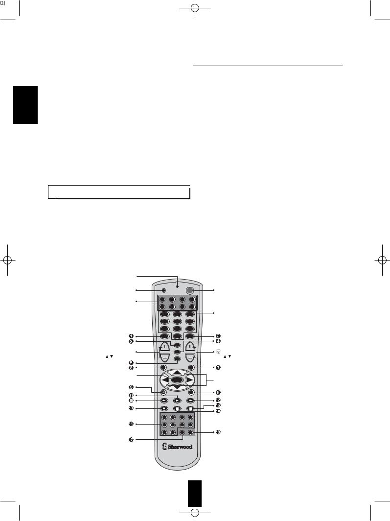
LED LAMP 
|
T |
|
|
|
|
SETUP BUTTON |
SE UP |
|
|
PWR |
POWER BUTTON |
|
|
|
|||
COMPONENT BUTTONS |
AUD |
CD |
DVD |
AUX |
|
|
|
|
|
|
|
• To operate the desired component |
SAT |
TV |
VCR |
CBL |
|
with this remotecontrol, first select the |
|
|
|
|
NUMERIC(1~0) BUTTONS |
corresponding COMPONENT button. |
1 |
|
2 |
3 |
|
|
|
|
|
|
• For selecting preset stations in tuner mode. |
|
4 |
|
5 |
6 |
• For selecting a track or a disc in CD mode, etc. |
|
7 |
|
8 |
9 |
• When selecting a disc, select disc No. (1~5) |
|
|
within 2 sec. after pressing DISC(marked "P.SCAN") button. |
|||
|
MUTE |
0 |
CH SEL |
|
|
|
|
|
P.SCAN |
|
|
VOLUME UP/DOWN |
|
|
SLEEP |
|
CHANNEL LEVEL UP/DOWN |
VOL |
|
|
CH LEVEL |
||
( / ) BUTTONS |
|
|
T.TONE |
|
( / ) BUTTONS |
|
|
D.TIME |
D.ADJ |
|
|
ENTER BUTTON 

ENTER
|
|
OSD |
|
AUTO |
STEREO |
|
|
DSP MODE |
6.1CH IN |
|
|
PHONO |
CD |
TUNER |
TAPE MON |
T2 MON |
VID SEL |
VID 2 |
VID 3 |
VID 4 |
AUX |
ROOM 2 |
SYS DISP |

 CURSOR CONTROL(
 ,
, ,
, ,
,  ) BUTTONS
•For moving an arrow with the CURSOR CONTROL buttons in the OSD mode.
HOME THEATER MASTER
RNC-30
1 0

FUNCTION TABLE of the NUMBERED BUTTONS. |
|
|
|
|
|||||
|
Component |
|
|
|
|
DVD (for DVD player) |
|
ENGLISH |
|
|
buttons to |
|
AUD |
CD |
AUX |
AUX |
|||
Button |
|
|
|
||||||
control |
(for receiver) |
(for CD player) |
(for tape deck) |
V-756, etc.("0633") |
VD-4106, etc.("0591") |
(for MD recorder) |
|
||
symbol |
|
|
|||||||
|
|
|
|
|
|
|
|
|
|
|
MUTE |
|
MUTE |
- |
- |
CLEAR |
- |
+10 |
|
|
CH SEL |
CHANNEL SELECTOR |
- |
- |
SEARCH |
- |
+100 |
|
|
|
P.SCAN |
PRESET SCAN |
DISC |
- |
OPEN/CLOSE |
RETURN |
EJECT |
|
|
|
|
|
|||||||
|
SLEEP |
|
SLEEP |
- |
- |
DISPLAY |
- |
AUTO SPACE |
|
|
|
|
|
||||||
|
T.TONE |
|
TEST TONE |
- |
- |
SET UP |
REPEAT A<->B |
DISPLAY |
|
|
|
|
|
||||||
|
D.TIME |
DELAY TIME |
REPEAT A<->B |
DECK SELECTOR A |
TITLE |
SETUP |
REPEAT |
|
|
|
D.ADJ |
DELAY ADJUST |
INTRO SCAN |
DECK SELECTOR B |
MENU |
CLEAR |
RANDOM |
|
|
|
|
|
- |
- |
REVERSE PLAY |
REVERSE SKIP |
DISPLAY |
REVERSE SKIP |
|
|
OSD |
ON-SCREEN DISPLAY |
- |
- |
FORWARD SKIP |
MENU |
FORWARD SKIP |
|
|
|
AUTO |
|
AUTO |
REVERSE SKIP |
REWIND |
REVERSE SEARCH |
REVERSE SCAN |
REVERSE SEARCH |
|
|
|
|
|
||||||
|
STEREO |
|
STEREO |
PLAY |
FORWARD PLAY |
PLAY |
PLAY |
PLAY |
|
|
|
|
|
||||||
|
|
|
- |
FORWARD SKIP |
FAST FORWARD |
FORWARD SEARCH |
FORWARD SCAN |
FORWARD SEARCH |
|
|
DSP MODE |
|
DSP MODE |
- |
RECORD |
RETURN |
- |
RECORD |
|
|
|
|
|
||||||
|
6.1CH IN |
6.1 CH DIRECT |
STOP |
STOP |
STOP |
STOP |
STOP |
|
|
|
|
|
|||||||
|
|
|
- |
PAUSE |
PAUSE |
PAUSE |
PAUSE |
PAUSE |
|
|
CD |
|
CD |
- |
- |
AUDIO |
- |
EDIT CANCEL |
|
|
|
I |
|
||||||
|
TUNER |
N |
TUNER |
- |
- |
ANGLE |
ANGLE |
DELETE/CLEAR |
|
|
|
P |
|
||||||
|
|
|
|
|
|
|
|
|
|
|
TAPE MON |
U |
TAPE |
- |
- |
ZOOM |
- |
CHARACTER/PROGRAM |
|
|
|
|
|||||||
|
|
T |
MONITOR |
|
|||||
|
VID SEL |
|
|
|
|
|
|
||
|
|
VIDEO |
- |
- |
REPEAT A<->B |
- |
RECORD INPUT |
|
|
|
|
|
|
||||||
|
|
S |
SELECTOR |
|
|||||
|
VID 2 |
|
|
|
|
|
|
||
|
E |
- |
- |
- |
RANDOM |
- |
AUTO/MANUAL |
|
|
|
|
|
|||||||
|
|
L |
|
||||||
|
VID 3 |
|
|
|
|
||||
|
E |
- |
- |
- |
INTRO SCAN |
- |
SPACE/CHECK |
|
|
|
|
|
|||||||
|
VID 4 |
C |
|
|
|
|
|
|
|
|
T |
- |
- |
- |
MARKER |
- |
TITLE INPUT |
|
|
|
|
|
|||||||
|
AUX |
O |
|
|
|
|
|
|
|
|
R |
AUX |
- |
- |
SUBTITLE |
- |
TITLE SEARCH |
|
|
|
|
|
|||||||
|
PHONO |
|
PHONO |
- |
- |
SUBTITLE ON/OFF |
SUBTITLE |
EDIT |
|
|
|
|
|
||||||
|
T2 MON |
|
- |
- |
- |
REPEAT MODE |
- |
RECORD MODE |
|
|
|
|
|
||||||
|
ROOM 2 |
ROOM 2 FEED |
- |
- |
PROGRAM |
- |
SET |
|
|
|
|
|
|||||||
|
SYS DISP |
SYSTEM DISPLAY |
- |
- |
TIME |
- |
ENTER |
|
|
|
|
|
|||||||
|
|
CURSOR UP( ) |
- |
- |
- |
(PAUSE) |
- |
|
|
|
|
CURSOR DOWN( ) |
- |
- |
- |
SLOW FORWARD |
- |
|
|
|
|
CURSOR RIGHT( ) |
- |
- |
- |
(FORWARD SCAN) |
- |
|
|
|
|
CURSOR LEFT( ) |
- |
- |
- |
(REVERSE SCAN) |
- |
|
|
|
ENTER |
|
ENTER |
- |
- |
- |
ENTER |
- |
|
|
CH LEVEL |
CH LEVEL UP( ) |
- |
- |
- |
FORWARD SKIP |
- |
|
|
|
|
|
|
|
|
|
|
|
|
|
CH LEVEL |
CH LEVEL DOWN( ) |
|
|
- |
REVERSE SKIP |
- |
|
|
|
|
- |
- |
|
|||||
Notes:
•Some functions for CD player, tape deck, etc. may not be available.
•For details about functions, refer to the operating instructions of each component.
1 1
 Loading...