


OPERATING INSTRUCTIONS
RD-5503
SURROUND RECEIVER
Introduction
READ THIS BEFORE OPERATING YOUR UNIT
CAUTION : TO REDUCE THE RISK OF ELECTRIC SHOCK, DO
NOT REMOVE COVER (OR BACK).
NO USER-SERVICEABLE PARTS INSIDE. REFER SERVICING TO QUALIFIED SERVICE PERSONNEL.
This symbol is intended to alert the user to the presence of uninsulated "dangerous voltage" within the product's enclosure that may be of sufficient magnitude to constitute a risk of electric shock to persons.
This symbol is intended to alert the user to the presence of important operating and maintenance (servicing) instructions in the literature accompanying the appliance.
WARNING : TO REDUCE THE RISK OF FIRE OR ELECTRIC SHOCK, DO NOT EXPOSE THIS APPLIANCE TO RAIN OR MOISTURE.
Caution regarding installation
Note : For heat dispersal, do not install this unit in a confined space such as a bookcase or similar enclosure.
Do not block ventilation openings or stack other equipment on the top.
FOR YOUR SAFETY
220 V
EUROPE
-
AUSTRALIA
240 V
Units shipped to Australia are designed for operation on 230 V AC only.
To ensure safe operation, the three-pin plug supplied must be inserted only into a standard three-pin power point which is effectively earthed through the normal household wiring. Extension cords used with the equipment must be three-core and be correctly wired to provide connection to earth.
Improper extension cords are a major cause of fatalities. The fact that the equipment operates satisfactorily does not imply that the power point is earthed and that the installation is completely safe. For your safety, if in any doubt about the effective earthing of the power point, consult a qualified electrician.
PAN-EUROPEAN UNIFIED VOLTAGE
All units are suitable for use on supplies 220-240 V AC.
CAUTION
•Leave a space around the unit for sufficient ventilation.
•Avoid installation in extremely hot or cold locations, or in an area that is exposed to direct sunlight or heating equipment.
•Keep the unit free from moisture, water, and dust.
•Do not let foreign objects in the unit.
•The ventilation should not be impeded by covering the ventilation openings with items, such as newspapers, table-cloths, curtains, etc.
•No naked flame sources, such as lighted candles, should be placed on the unit.
•Please be care the environmental aspects of battery disposal.
•The unit shall not be exposed to dripping or splashing for use.
•No objects filled with liquids, such as vases, shall be placed on the unit.
•Do not let insecticides, benzene, and thinner come in contact with the set.
•Never disassemble or modify the unit in any way.
Notes on the AC power cord and the wall outlet.
•The unit is not disconnected from the AC power source(mains) as long as it is connected to the wall outlet, even if the unit has been turned off.
•To completely disconnect this product from the mains, disconnect the plug from the wall socket outlet.
•When setting up this product, make sure that the AC outlet you are using is easily acceptable.
•Disconnect the plug from the wall outlet when not using the unit for long periods of time.
Note on recycling
This product’s packaging materials are recyclable and can be reused. Please dispose of any materials in accordance with the local recycling regulations.
When discarding the unit, comply with local rules or regulations.
Batteries should never be thrown away or incinerated but disposed of in accordance with the local regulations concerning chemical waste.
This product and the accessories packed together constitute the applicable product according to the WEEE directive except batteries.
ENGLISH
2

ENGLISH
CONTENTS |
|
Introduction |
|
• READ THIS BEFORE OPERATING YOUR UNIT ................................................................................................................. |
2 |
System Connections ......................................................................................................................................................... |
4 |
Front Panel Controls ......................................................................................................................................................... |
8 |
Remote Controls ................................................................................................................................................................. |
9 |
• REMOTE CONTROL OPERATION RANGE ....................................................................................................................... |
10 |
• LOADING BATTERIES ....................................................................................................................................................... |
10 |
Operations |
|
• LISTENING TO A PROGRAM SOURCE ............................................................................................................................ |
11 |
• SURROUND SOUND .......................................................................................................................................................... |
14 |
• ENJOYING SURROUND SOUND ...................................................................................................................................... |
15 |
• LISTENING TO RADIO BROADCASTS ............................................................................................................................. |
20 |
• LISTENING TO RDS BROADCASTS (FM ONLY) .............................................................................................................. |
22 |
( RDS Tuner (Regional Option for some countries in Europe, etc)) |
|
• RECORDING ....................................................................................................................................................................... |
24 |
• OTHER FUNCTIONS .......................................................................................................................................................... |
25 |
• USING DIFFERENT FUNCTIONS ON THE FRONT PANEL ............................................................................................. |
26 |
System Setup .................................................................................................................................................................... |
27 |
• SETTING THE SYSTEM .................................................................................................................................................... |
29 |
• SETTING THE INPUT ......................................................................................................................................................... |
31 |
• SETTING THE SPEAKER SETUP ...................................................................................................................................... |
32 |
• SETTING THE CH LEVEL .................................................................................................................................................. |
36 |
• SETTING THE PARAMETER ............................................................................................................................................. |
38 |
Troubleshooting Guide ................................................................................................................................................... |
40 |
Specifications .................................................................................................................................................................... |
41 |
3

System Connections
•Please be certain that this unit is unplugged from the AC outlet before making any connections.
•Be sure to observe the color coding when connecting audio, video and speaker cords.
•Make connections firmly and correctly. If not, it can cause loss of sound, noise or damage to the receiver.
3 |
|
|
6 |
ENGLISH |
|
|
|
||
2 |
4 |
1 |
5 |
|
1. CONNECTING ANTENNAS
•Change the position of the FM indoor antenna until you get the best reception of your favorite FM stations.
•A 75Ω outdoor FM antenna may be used to further improve the reception. Disconnect the indoor antenna before replacing it with the outdoor one.
•Place the AM loop antenna as far as possible from the receiver, TV set, speaker cords and the AC input cord and set it to a direction for the best reception.
•If the reception is poor with the AM loop antenna, an AM outdoor antenna can be used in place of the AM loop antenna.
4
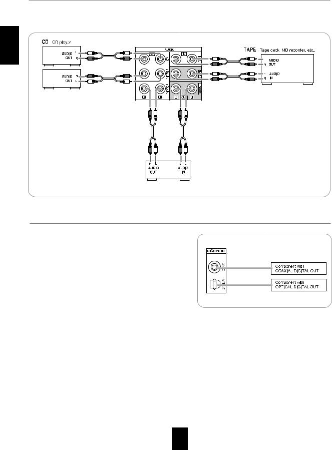
2. CONNECTING AUDIO/VIDEO COMPONENTS
•The VIDEO 1/VIDEO 2 jacks may be connected to AUDIO jacks of video components such as DVD player, TV, etc..
•The TAPE IN/OUT jacks and the VIDEO 1 IN/OUT jacks can be connected to audio recording equipment such as a tape deck, an MD recorder, etc..
ENGLISH
VIDEO 2 DVD player, TV, etc.
VIDEO 1 DVD player, tape deck, MD recorder, etc.
3. CONNECTING DIGITAL INs
•The OPTICAL and the COAXIAL DIGITAL OUTs of the components that are connected to CD and VIDEO 1 of this unit can be connected to these DIGITAL INs.
•A digital input should be connected to the components such as a CD player, LD player, DVD player, etc. capable of outputting
Dolby Digital or PCM format digital signals, etc.
•For details, refer to the operating instructions of the component connected.
•When making the COAXIAL DIGITAL connection, be sure to use a 75Ω COAXIAL cord, not a conventional AUDIO cord.
•All of the commercially available optical fiber cords cannot be used for the equipment. If there is an optical fiber cord which cannot be connected to your equipment, consult your dealer or nearest service organization.
Note : Be sure to make either a OPTICAL or a COAXIAL DIGITAL connection on each component. (You don’t need to do both.)
5
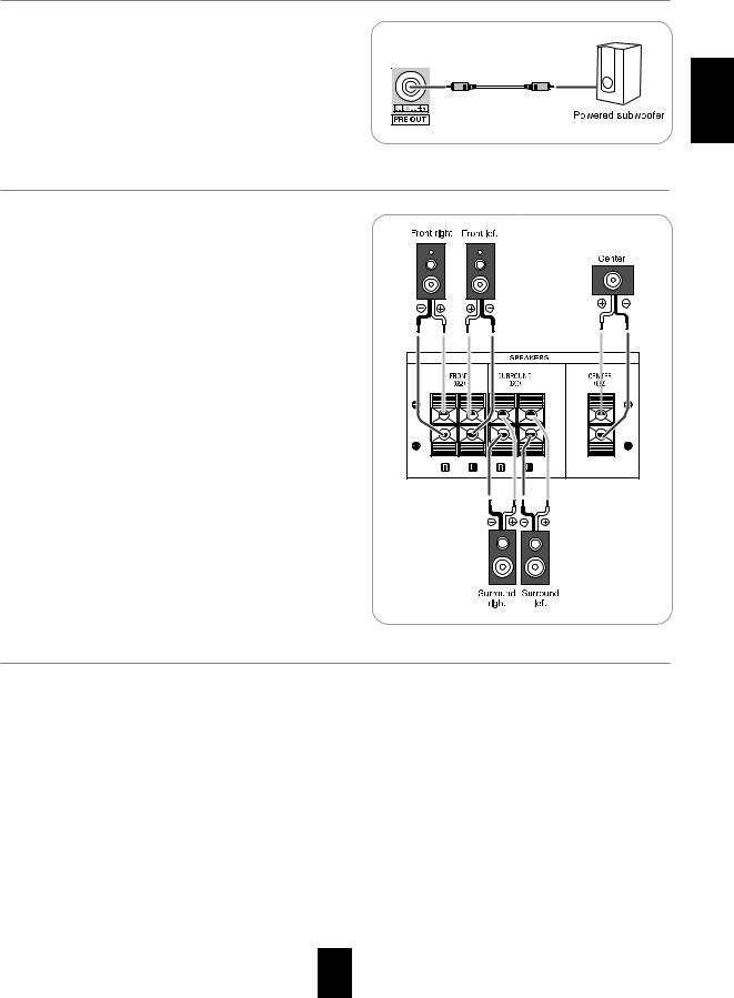
4. CONNECTING SUBWOOFER PRE OUT
•To emphasize the deep bass sounds, connect a powered subwoofer.
ENGLISH
5. CONNECTING SPEAKERS
•Be sure to connect speakers firmly and correctly according to the channel(left and right) and the polarity(+ and -). If the connections are faulty, no sound will be heard from the speakers, and if the polarity of the speaker connection is incorrect, the sound will be unnatural and lack bass.
•For installing the speakers, refer to "Speaker placement" on page 7.
•After installing the speakers, first adjust the speaker settings according to your environment and speaker layout.
(For details, refer to "SETTING THE SPEAKER SETUP" on page 32.)
Caution :
•Be sure to use the speakers with the impedance of 6 ohms or above.
•Do not let the bare speaker wires touch each other or any metal part of this unit. This could damage this unit and/or the speakers.
6. AC INPUT CORD
• Plug the cord into a wall AC outlet.
6
ENGLISH
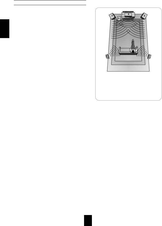
Speaker placement
Ideal speaker placement varies depending on the size of your room and the wall coverings, etc. The typical example of speaker placement and recommendations are as follows :
Front left and right speakers and center speaker
•Place the front speakers with their front surfaces as flush with
TV or monitor screen as possible.
•Place the center speaker between the front left and right speakers and no further from the listening position than the front speakers.
•Place each speaker so that sound is aimed at the location of the listener’s ears when at the main listening position.
Surround left and right speakers
•Place the surround speakers approximately 1 meter (40 inches) above the ear level of a seated listener on the direct left and right of them or slightly behind.
Subwoofer
•The subwoofer reproduces powerful deep bass sounds. Place a subwoofer anywhere in the front as
desired.
Notes :
•When using a conventional TV, to avoid interference with the
TV picture, use only magnetically shielded front left and right and center speakers.
•To obtain the best surround effects, the speakers except the subwoofer should be full range speakers.
1.TV or screen
2.Front left speaker
3.Front right speaker
4.Center speaker
5.Subwoofer
6.Surround left speaker
7.Surround right speaker
7
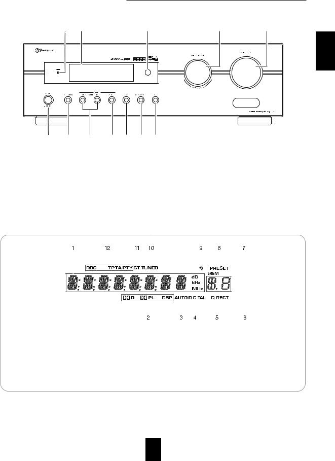
Front Panel Controls |
|
|
|
|
|||
|
3 |
4 |
|
|
5 |
6 |
7 |
|
|
|
|
|
|
|
ENGLISH |
1 |
2 |
8 |
9 |
10 |
11 |
12 |
|
1. POWER switch |
7. MASTER VOLUME CONTROL knob |
|
2. POWER ON/STANDBY button |
8. SURROUND MODE UP/DOWN ( |
) buttons |
3. STANDBY indicator |
9. STEREO button |
|
4. FLUORESCENT DISPLAY |
10. BAND button |
For details, see below. |
11. MEMORY/ENTER button |
5. REMOTE SENSOR |
12. MODE button |
6. INPUT SELECTOR/MULTI CONTROL knob |
|
FLUORESCENT DISPLAY
|
|
|
|
|
|
|
|
|
|
|
|
|
|
|
|
|
|
|
|
|
|
|
|
|
|
|
|
|
|
|
|
|
|
|
|
|
|
|
|
|
|
|
|
|
|
|
|
|
|
|
|
|
|
|
|
|
|
|
|
|
|
|
|
|
|
|
|
|
|
|
|
|
|
|
|
|
|
|
|
|
|
|
|
|
|
|
|
|
|
|
|
|
|
|
|
|
|
|
|
|
|
|
|
|
|
|
|
|
|
|
|
|
|
|
|
|
|
|
|
|
|
|
|
|
|
|
|
|
|
|
|
|
|
|
|
|
|
|
|
|
|
|
|
|
|
|
|
|
|
|
|
|
|
|
|
|
|
|
|
|
|
|
|
|
|
|
|
|
|
|
|
|
|
|
|
|
|
|
|
|
|
|
|
|
|
|
|
|
|
|
|
|
|
|
|
|
|
1. |
Input, frequency, volume level, |
7. |
MEMORY indicator |
||||||||||||||||||
|
operating information, etc. |
8. |
PRESET indicator |
||||||||||||||||||
2. |
Surround mode indicators |
9. |
SLEEP indicator |
||||||||||||||||||
3. |
AUTO indicator |
10. |
TUNED indicator |
||||||||||||||||||
4. |
DIGITAL INPUT indicator |
11. |
STEREO indicator |
||||||||||||||||||
5. |
DIRECT indicator |
12. |
RDS indicators |
||||||||||||||||||
6. |
Preset number, sleep time display |
|
|
(Regional option for Europe, etc.) |
|||||||||||||||||
8
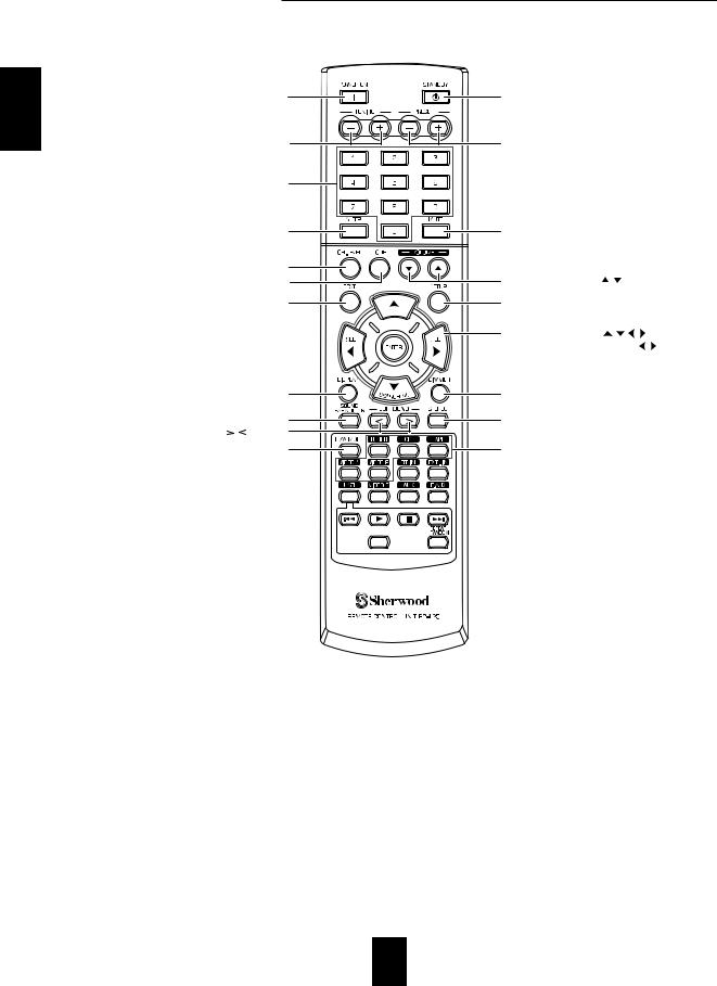
Remote Controls
ENGLISH
POWER ON button |
STANDBY button |
|
|
|
TUNING UP/DOWN(+/-) buttons |
PRESET UP/DOWN(+/-) buttons |
|||
NUMERIC(0~9) buttons |
|
|
|
|
SLEEP button |
MUTE button |
|
|
|
CHANNEL LEVEL button |
|
|
|
|
TONE MODE button |
VOLUME UP/DOWN( |
/ |
) buttons |
|
TEST TONE button |
SETUP button |
|
|
|
|
CURSOR CONTROL( |
, |
, |
, ), ENTER |
|
</SEARCH MODE, SELECT |
/ > buttons |
||
|
• The functions in "< >" are regional option |
|||
|
for Europe, etc. |
|
|
|
DISPLAY button |
DIMMER button |
|
|
|
SOUND PARAMETER button |
STEREO button |
|
|
|
SURROUND MODE UP/DOWN( / ) buttons |
|
|
|
|
DIGITAL/ANALOG MODE button |
INPUT SELECTOR buttons |
|
||
|
|
|
|
|
|
|
|
|
|
Note: Some input selector buttons(BT IN, EXT. IN, USB, VIDEO 3, AUX, F.AUX) and USB transport buttons( |
, |
|||
, REPEAT/RANDOM) are not available for this unit. |
|
|||
9
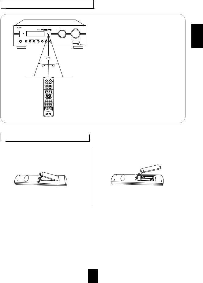
REMOTE CONTROL OPERATION RANGE
ENGLISH
•Use the remote control unit within a range of about 7 meters (23 feet) and angles of up to 30 degrees aiming at the remote sensor.
LOADING BATTERIES
1. Remove the cover. |
2. Load two batteries ("AAA" size, 1.5 V) matching the |
|
|
|
polarity. |
|
||
|
|
|
• Remove the batteries when they are not used for a long time.
• Do not use the rechargeable batteries (Ni-Cd type).
10
ENGLISH
Operations
Note : Before operating this receiver, first set this unit as desired for optimum performance, doing the system setup procedures. (For details, refer to "System Setup" on page 27.)
LISTENING TO A PROGRAM SOURCE
Before operation
•Enter the standby mode.
•The STANDBY indicator lights up.
This means that the receiver is not
disconnected from the AC mains and a small amount of current is retained to support the operation readiness.
•To switch the power off, push the POWER switch again.
•Then the power is cut off and the STANDBY indicator goes off.
1.In the standby mode, turn the power on.
or
•Each time the POWER ON/STANDBY button on the front panel is pressed, the receiver is turned on to enter the operating mode or off to enter the standby mode.
•On the remote control, press the POWER ON button to enter the operating mode or press the STANDBY button to enter the standby mode.
•In the standby mode, if the INPUT SELECTOR button is pressed or the INPUT SELECTOR/MULTI CONTROL knob is rotated, the receiver is turned on automatically and the desired input is selected.
2. Select the desired input source.
or
or
•Each time the INPUT SELECTOR/MULTI CONTROL knob is rotated , the input source changes as follows:
TUNER |
CD TAPE VIDEO 1 VIDEO 2 |
(Frequency display)
•Each time the BAND button on the front panel or the TUNER button on the remote control is pressed, the band changes as follows:
|
FM ST |
FM MONO AM |
|
|
|
||
|
|
|
|
11
When CD, VIDEO 1 is selected as an input source
3. Select the digital or the analog input connected as desired.
•Each time this button is pressed, the corresponding input is selected as follows:
o(ptical) c(oaxial) A(nalog)
Notes :
•When TUNER, TAPE or VIDEO 2 is selected as an input source, the digital input cannot be selected.
•When the selected digital input is not connected, the
"DIGITAL" indicator flickers and the analog input is automatically selected.
•The selected digital or analog input is automatically assigned to the corresponding input source on the INPUT setup menu. (For details, refer to "SETTING THE INPUT " on page 31.)
•The sound from the component connected to the selected digital input can be heard regardless of the selected input source.
4.Operate the selected component for playback.
•When playing back the program sources with surround sound, refer to “ENJOYING SURROUND SOUND” on page 15.
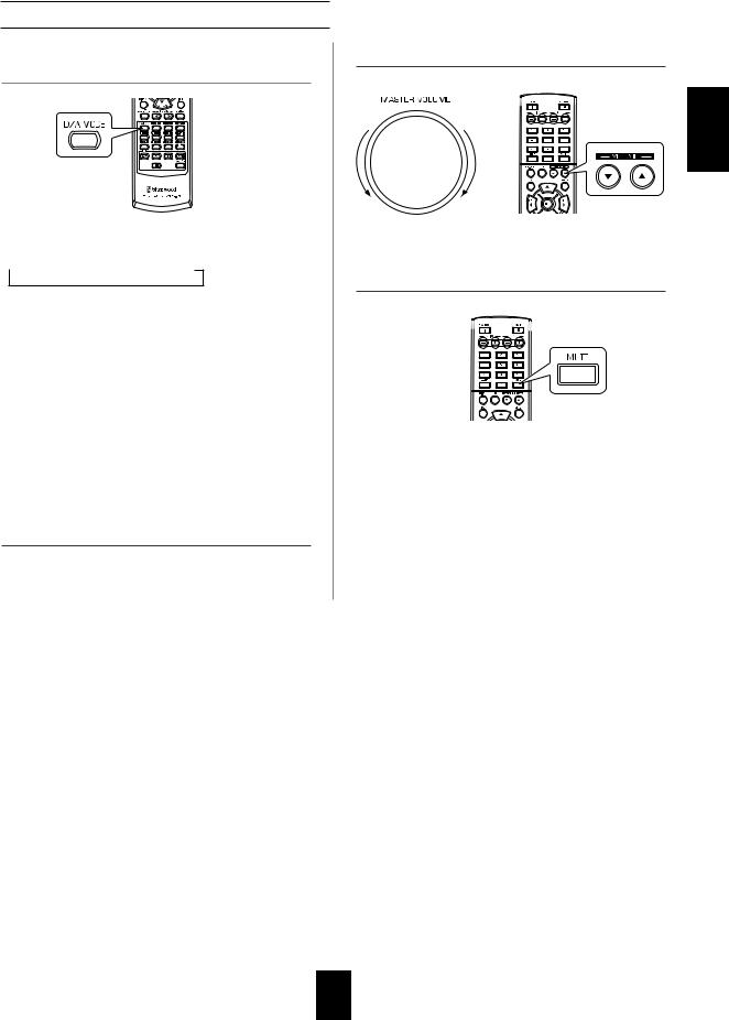
5. Adjust the (overall) volume.
or
DOWN |
UP |
6. To mute the sound.
•“MUTE” will flicker.
•To resume the previous sound level, press it again.
ENGLISH
12
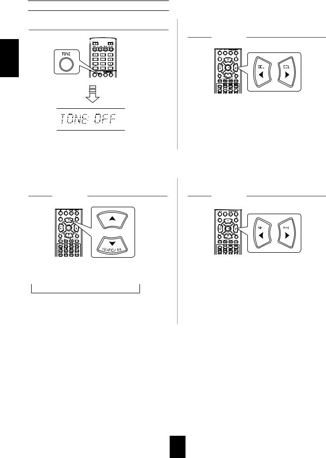
Adjusting the tone (bass and treble)
7. Enter the tone mode.
ENGLISH
• The tone mode is displayed for several seconds.
8. Press the CURSOR LEFT( )/RIGHT( ) buttons to select the desired tone mode.
•Each time these buttons are pressed, the tone mode is selected as follows :
OFF : To listen to a program source without the tone effect.
("DIRECT" indicator lights up.)
ON : To adjust the tone for your taste. ("DIRECT" indicator goes off.)
When the TONE is set to ON to adjust the tone (bass and treble).
9. Press the CURSOR UP( )/DOWN( ) buttons to select the desired tone.
•Each time these buttons are pressed, the tone is selected as follows :
BASS |
TRBL (treble) |
TONE ON |
10. Press the CURSOR LEFT( )/RIGHT( ) buttons to adjust the selected tone as desired.
•The tone level can be adjusted within the range of -10 ~ +10 dB.
•In general, we recommend the bass and treble to be adjusted to 0 dB (flat level).
•Extreme settings at high volume may damage your speakers.
•To complete tone adjustment, repeat the above steps 9 and 10.
•If the tone display disappears, start from the step 7 again.
13
 Loading...