


RD-7502
RD-7502
ENGLISH
2
1. Read Instructions - All the safety and operating instructions should
be read before the product is operated.
2. Retain instructions - The safety and operating instructions should
be retained for future reference.
3. Heed Warnings - All warnings on the product and in the operating
instructions should be adhered to.
4. Follow Instructions - All operating and use instructions should be
followed.
5. Cleaning - Unplug this product from the wall outlet before cleaning.
Do not use liquid cleaners or aerosol cleaners. Use a damp cloth for
cleaning.
6. Attachments - Do not use attachments not recommended by the
product manufacturer as they may cause hazards.
7. Water and Moisture - Do not use this product near water - for
example, near a bath tub, wash bowl, kitchen sink, or laundry tub; in
a wet basement, or near a swimming pool; and the like.
8. Accessories - Do not place this product on an unstable cart, stand,
tripod, bracket, or table. The product may fall, causing serious injury
to a child or adult, and serious damage to the product. Use only with
a cart, stand, tripod, bracket, or table recommended by the
manufacturer, or sold with the product. Any mounting of the product
should follow the manufacturer’s instructions, and should use a
mounting accessory recommended by the
manufacturer.
9. A product and cart combination should be
moved with care. Quick stops, excessive
force, and uneven surfaces may cause the
product and cart combination to overturn.
10. Ventilation - Slots and openings in the
cabinet are provided for ventilation and to
ensure reliable operation of the product
and to protect it from overheating, and
these openings must not be blocked or covered. The openings
should never be blocked by placing the product on a bed, sofa, rug,
or other similar surface. This product should not be placed in a
built-in installation such as a bookcase or rack unless proper
ventilation is provided or the manufacturer’s instructions have been
adhered to.
11. Power Sources - This product should be operated only from the
type of power source indicated on the marking label. If you are not
sure of the type of power supply to your home, consult your product
dealer or local power company. For products intended to operate
from battery power, or other sources, refer to the operating
instructions.
12. Grounding or Polarization - This product may be equipped with a
polarized alternating-current line plug (a plug having one blade
wider than the other). This plug will fit into the power outlet only one
way. This is a safety feature. If you are unable to insert the plug
fully into the outlet, try reversing the plug. If the plug should still fail
to fit, contact your electrician to replae your obsolete outlet. Do not
defeat the safety purpose of the polarized plug.
Alternate Warnings - This product is equipped with a three-wire
grounding-type plug, a plug having a third(grounding) pin. This plug
will only fit into a grounding-type power outlet. this is a safety
feature. If you are unable to insert the plug into the outlet, contact
your electrician to replace your obsolete outlet. Do not defeat the
safety purpose of the grounding-type plug.
13. Power-Cord Protection - Power-supply cords should be routed so
that they are not likely to be walked on or pinched by items placed
upon or against them, paying particular attention to cords at plugs,
convenience receptacles, and the point where they exit from the
product.
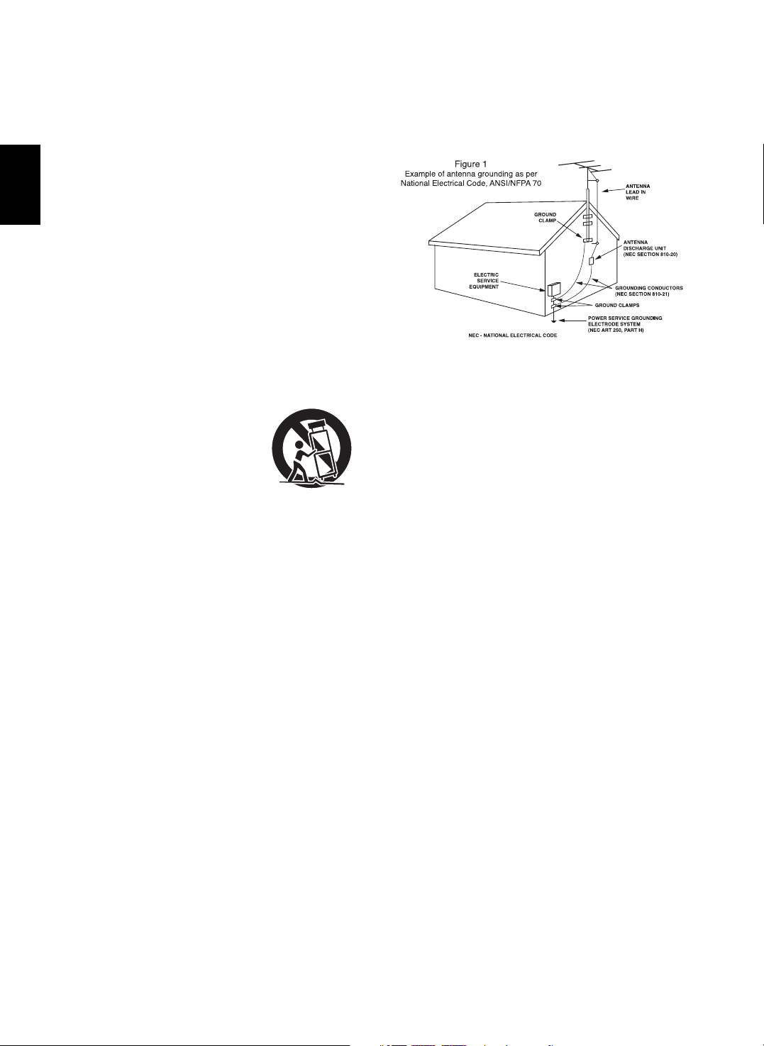
14. Outdoor Antenna Grounding - If an outside antenna or cable
system is connected to the product, be sure the antenna or cable
system is grounded so as to provide some protection against
voltage surges and built-up static charges. Article 810 of the
National Electrical Code, ANSI/NFPA 70, provides information with
regard to proper grounding of the mast and supporting structure,
grounding of the lead-in wire to an antenna discharge unit, size of
grounding conductors, location of antenna-discharge unit,
connection to grounding electrodes, and requirements for the
grounding electrode. See Figure 1.
15. Lightning - For added protection for this product during a lightning
storm, or when it is left unattended and unused for long periods of
time, unplug it from the wall outlet and disconnect the antenna or
cable system. This will prevent damage to the product due to
lightning and power-line surges.
16. Power Lines - An outside antenna system should not be located in
the vicinity of overhead power lines or other electric light or power
circuits, or where it can fall into such power lines or circuits. When
installing an outside antenna system, extreme care should be taken
to keep from touching such power lines or circuits as contact with
them might be fatal.
17. Overloading - Do not overload wall outlets, extension cords, or
integral convenience receptacles as this can result in a risk of fire
or electric shock.
18. Object and Liquid Entry - Never push objects of any kind into this
product through openings as they may touch dangerous voltage
points or short-out parts that could result in a fire or electric shock.
Never spill liquid of any kind on the product.
19. Servicing - Do not attempt to service this product yourself as
opening or removing covers may expose you to dangerous voltage
or other hazards. Refer all servicing to qualified service personnel.
20. Damage Requiring Service - Unplug this product form the wall
outlet and refer servicing to qualified service personnel under the
following conditions:
a) When the power-supply cord or plug is damaged,
b) If liquid has been spilled, or objects have fallen into the
product,
c) If the product has been exposed to rain or water,
d) If the product does not operate normally by following the
operating instructions. Adjust only those controls that are
covered by the operating instructions as an improper
adjustment of other controls may result in damage and will
often require extensive work by a qualified technician to
restore the product to its normal operation.
e) If the product has been dropped or damaged in any way, and
f) When the product exhibits a distinct change in performance -
this indicates a need for service.
21. Replacement Parts - When replacement parts are required, be
sure the service technician has used replacement parts specified
by the manufacturer or have the same characteristics as the
original part. Unauthorized substitutions may result in fire, electric
shock, or other hazards.
22. Safety Check - Upon completion of any service or repairs to this
product, ask the service technician to perform safety checks to
determine that the product is in proper operating condition.
23. Wall or Ceiling Mounting - The product should be mounted to a
wall or ceiling only as recommended by the manufacturer.
24. Heat - The product should be situated away from heat sources
such as radiators, heat registers, stoves, or other products
(including amplifiers) that produce heat.
PORTABLE CART WARNING
SAFETY INSTRUCTIONS
CAUTION
FOR YOUR SAFETY
3
ENGLISH
: TO REDUCE THE RISK OF FIRE OR ELECTRIC SHOCK,
DO NOT EXPOSE THIS APPLIANCE TO RAIN OR MOISTURE.
Introduction
READ THIS BEFORE OPERATING YOUR UNIT
This symbol is intended to alert the user to the presence of
uninsulated "dangerous voltage" within the product's
enclosure that may be of sufficient magnitude to constitute a
risk of electric shock to persons.
This symbol is intended to alert the user to the presence of
important operating and maintenance (servicing) instructions
in the literature accompanying the appliance.
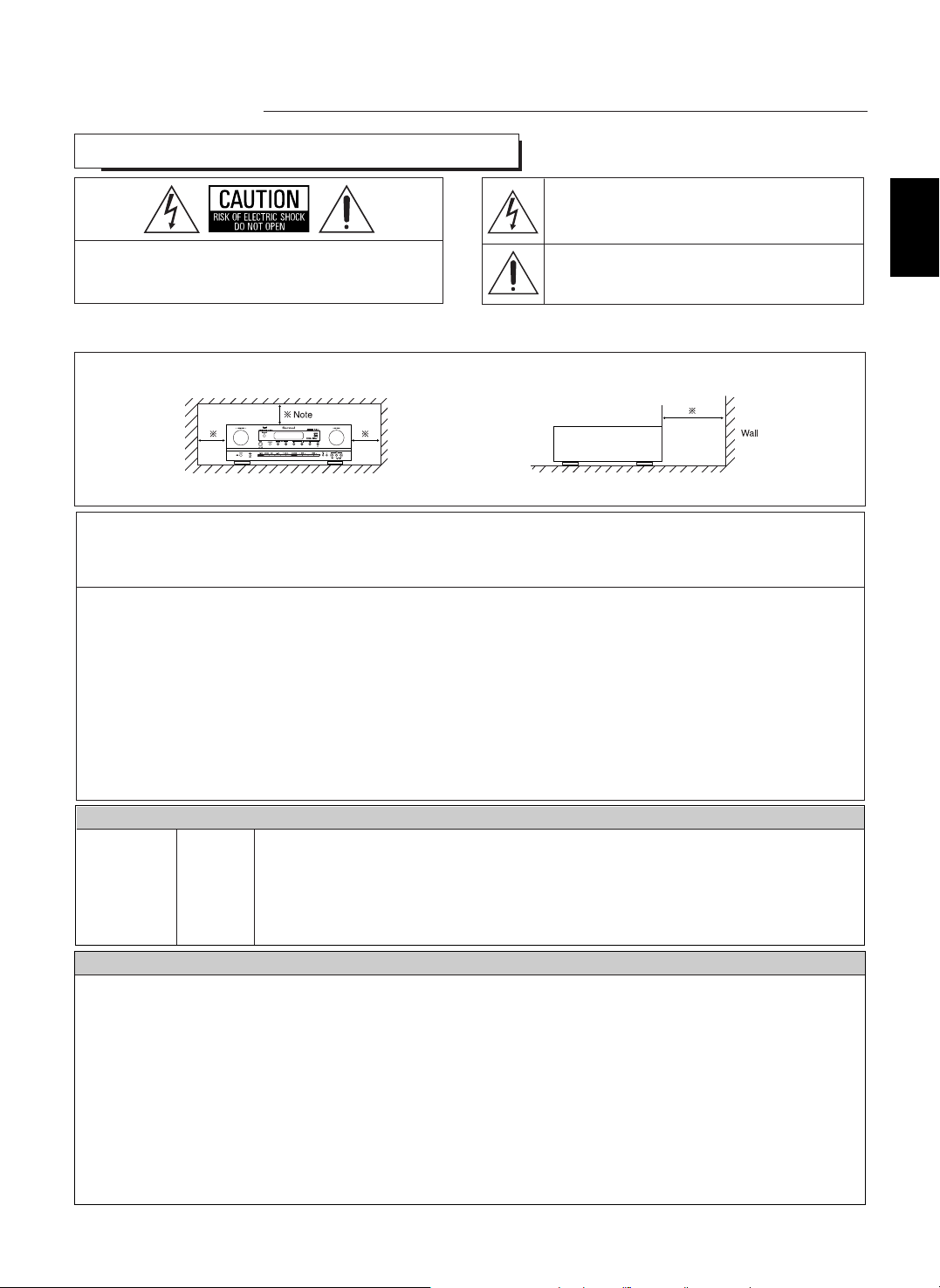
Caution regarding installation
Note : For heat dispersal, do not install this unit in a confined space such as a bookcase or similar enclosure.
: TO REDUCE THE RISK OF ELECTRIC SHOCK, DO
NOT REMOVE COVER (OR BACK). NO USERSERVICEABLE PARTS INSIDE. REFER SERVICING
TO QUALIFIED SERVICE PERSONNEL.
CAUTION
WARNING
Units shipped to the U.S.A and CANADA are designed for operation on 120 V AC only.
Safety precaution with use of a polarized AC plug.
However, some products may be supplied with a nonpolarized plug.
U.S.A
CANADA
120 V
•
Leave a space around the unit for sufficient ventilation.
•
Avoid installation in extremely hot or cold locations, or in an area that is exposed to direct sunlight or heating equipment.
•
Keep the unit free from moisture, water, and dust.
•
Do not let foreign objects in the unit.
•
The ventilation should not be impeded by covering the ventilation openings with items, such as newspapers, table-cloths, curtains, etc.
•
No naked flame sources, such as lighted candles, should be placed on the unit.
•
Please be care the environmental aspects of battery disposal.
•
The unit shall not be exposed to dripping or splashing for use.
•
No objects filled with liquids, such as vases, shall be placed on the unit.
• Do not let insecticides, benzene, and thinner come in contact with the set
.
•
Never disassemble or modify the unit in any way.
■Notes on the AC power cord and the wall outlet.
•
The unit is not disconnected from the AC power source(mains) as long as it is connected to the wall outlet, even if the unit has been turned off.
•
When disconnecting the power cord from the wall outlet, always pull the plug, not the power cord.
•
Disconnect the plug from the wall outlet when not using the unit for long periods of time.
•
The wall outlet shall be installed near the unit and shall be easily accessible.
Do not block ventilation openings or stack other equipment on the top.
: To prevent electric shock, match wide blade of plug to wide slot, fully insert.
: Pour éviter chocs électriques, introduire la lame la plus large de la fiche dans la borne
correspondante de la prise et pousser jusqu’ au fond.
CAUTION
ATTENTION
Note to CATV System Installer :
This reminder is provided to call the CATV system installer’s attention to Article 820-40 of the NEC that provides guidelines for proper
grounding and, in particular, specifies that the cable ground shall be connected to the grounding system of the building, as close to the point
of cable entry as practical.
FCC INFORMATION
This equipment has been tested and found to comply with the limits for a Class B digital device, pursuant to Part 15 of the FCC Rules. These
limits are designed to provide reasonable protection against harmful interference in a residential installation. This equipment generates, uses and
can radiate radio frequency energy and, if not installed and used in accordance with the instructions, may cause harmful interference to radio
communications. However, there is no guarantee that interference will not occur in a particular installation. If this equipment does cause harmful
interference to radio or television reception, which can be determined by turning the equipment off and on, the user is encouraged to try to correct
the interference by one or more of the following measures:
• Reorient or relocate the receiving antenna.
• Increase the separation between the equipment and receiver.
• Connect the equipment into an outlet on a circuit different from that to which the receiver is connected.
• Consult the dealer or an experienced radio/TV technician for help.
Caution : Any changes or modifications in construction of this device which are not expressly approved by the party responsible for compliance
could void the user’s authority to operate the equipment.

ENGLISH
4
CONTENTS
SAFETY INSTRUCTIONS | 2
Introduction
• READ THIS BEFORE OPERATING YOUR UNIT | 3
System Connections | 5
Front Panel Controls | 11
Remote Controls | 13
• REMOTE CONTROL OPERATION RANGE | 14
• LOADING BATTERIES | 14
Operations
• LISTENING TO A PROGRAM SOURCE | 15
• SURROUND SOUND | 18
• ENJOYING SURROUND SOUND | 20
• LISTENING TO RADIO BROADCASTS | 26
• LISTENING TO XM SATELLITE RADIO
(XM Satellite Radio (only for North America)) | 28
• RECORDING | 31
• DIGITAL AUDIO RECORDING WITH MD RECORDER | 32
• OTHER FUNCTIONS | 33
System Setup | 34
• SETTING THE SYSTEM | 37
• SETTING THE INPUT | 39
• SETTING THE SPEAKER SETUP | 41
• SETTING THE CH LEVEL | 48
• SETTING THE SOUND PARAMETER | 50
Troubleshooting Guide | 54
Specifications | 55
5
System Connections
• Do not plug the AC input cord into the wall AC outlet until all connections are completed.
• Be sure to observe the color coding when connecting audio, video and speaker cords.
• Make connections firmly and correctly. If not, it can cause loss of sound, noise or damage to the receiver.
RLR
L
R
L
FRONT
(6 )
SURROUND
(6 )
CENTER
(6 )
SURROUND BACK
(6 )
SPEAKERS
AC INPUT
120V~60Hz
3.8A
SN.
MADE IN CHINA
DESIGNED IN USA
MODEL NO.
RD-7502
AUDIO/VIDEO RECEIVER
This device complies with Part 15 of the FCC rules.
Operation is subject to the following two conditions:
(1)This device may not cause harmful interference,and
(2)This device must accept any interference received,
including interference that may cause undesired operation.
AC OUTLET
120V~60Hz
SWITCHED
TOTAL 120W(1A) MAX.
Manufactured under license from Digital
Theater Systems, Inc. U.S. Pat. No's.
5,451,942; 5,956,674; 5,974,380; 5,978,762; 6,487,535 and other
U.S. and world-wide patents issued and pending.
"DTS", "DTS-ES", "DTS 96/24" and "Neo:6" are trademarks of
Digital Theater Systems, Inc. Copyright 1996, 2003-2005 Digital
Theater Systems, Inc. All Rights Reserved.
Manufactured under license from Dolby Laboratories.
"Dolby", "Pro Logic", and the double-D symbol are
trademarks of Dolby Laboratories.
CD
TAPE
SURROUND
CENTER
FRONT
DIGI-LINKPRE OUT
VIDEO
COAX 1OPT 1 OPT 2
VIDEO 1 VIDEO 2
VIDEO 1 VIDEO 2
COAX 2
FM
75
R
L
R
L
AUDIO S-VIDEO COMPONENT VIDEODIGITAL
EXTERNAL IN
Y
PR/CR PB/CB
XM
ANTENNA
MONITOR OUT
OPT OUT
VIDEO 1 OUT
SUBWOOFER
PB/CB
Y
PR/CR
PB/CB
Y
PR/CR
VIDEO 1 VIDEO 2
VIDEO 1 OUT
MONITOR OUT
SUBWOOFER SUR.BACK
TAPE OUT
AM
LOOP
GND
MONITOR OUT
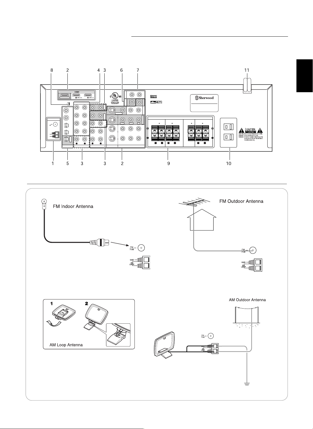
1. CONNECTING ANTENNAS
• Change the position of the FM indoor antenna until you
get the best reception of your favorite FM stations.
• Place the AM loop antenna as far as possible from
the receiver, TV set, speaker cords and the AC
input cord and set it to a direction for the best
reception.
• If the reception is poor with the AM loop antenna,
an AM outdoor antenna can be used in place of
the AM loop antenna.
• A 75Ω outdoor FM antenna may be used to further
improve the reception. Disconnect the indoor
antenna before replacing it with the outdoor one.
ENGLISH
ENGLISH
6
TAPE
VIDEO
VIDEO 1 VIDEO 2
VIDEO 1 VIDEO 2
R
L
AUDIO S-VIDEO COMPONENT VIDEO
Y
PR/CR PB/CB
MONITOR OUT
VIDEO 1 OUT
PB/CB
Y
PR/CR
PB/CB
Y
PR/CR
VIDEO 1 VIDEO 2
VIDEO 1 OUT
VIDEO
VIDEO 2
VIDEO 2
Y
PR/CR PB/CB
MONITOR OUT
PB/CB
Y
PR/CR
VIDEO 1 VIDEO 2
VIDEO
MONITOR OUT
PB/CB
Y
PR/CR
VIDEO 2
MONITOR OUT
MONITOR OUT
COMPONENT
OUT
Y C
B CR
AUDIO
OUT
R L
AUDIO
IN
S-VIDEO
OUT IN
(COMPOSITE)
VIDEO
HDMI
OUT
IN
OUT
COMPONENT
IN
Y C
B CR
S-VIDEO
IN
(COMPOSITE)
VIDEO
HDMI
IN
IN
COMPONENT
OUT
Y C
B CR
AUDIO
OUT
L R
S-VIDEO
OUT
(COMPOSITE)
VIDEO
HDMI
OUT
OUT
R L
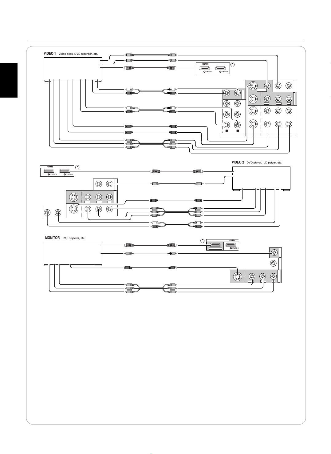
• The jacks of VIDEO 1 may also be connected to a DVD recorder or other digital video recording component.
For details, refer to the operating instructions of the component to be connected.
• The jacks of VIDEO 2 can also be connected to an additional video component such as a cable TV tuner, an LD
player or satellite system.
Note :
• When Sherwood DVD player such as V-768, etc. is connected to the DIGI-LINK jack for system control, you should
connect the DVD player to the " VIDEO 2" jacks of this unit.
Because, if the PLAY button, etc. is pressed on the DVD player, the VIDEO 2 is automatically selected as an input
source on this unit. Then playback, etc. starts.
HDMI(High Definition Multimedia Interface) connection : (*)
• You can connect the source component (DVD player, etc.) to the display component (TV, projector, etc.) through this
receiver with using a commercially available HDMI cord.
• The HDMI connection can carry uncompressed digital video signals and digital audio signals.
• This receiver can output digital video and digital audio signals from the MONITOR HDMI OUT of this receiver without
passing through any circuits as they were input into the HDMI IN.
• HDMI, the HDMI logo and High-Definition Multimedia Interface are trademarks or registered trademarks of HDMI
licensing LLC.
Note: Depending on the connected component, unreliable signal transfer may happen.
(For details, refer to the operating instruction of your component.)
2. CONNECTING VIDEO COMPONENTS
7
Relationship between the video input signal and the video output signal
*1 : Component video signal can be output from the MONITOR COMPONENT OUT jacks only.
*2 : The video signal set in the VIDEO MODE menu can be output from all the types of MONITOR OUT jacks.
Video input signals Video Mode MONITOR OUTs
COMPONENT S-VIDEO (composite) VIDEO Setting COMPONENT S-VIDEO (composite) VIDEO
“AT”(Auto) Component S-Video Composite video
“CPN”(Component)
*1
Component ××
“SVD”(S-Video)
*2
S-Video S-Video S-Video
“CPS”(Composite)*2Composite video Composite video Composite video
× “AT”(Auto) Component S-Video S-Video
× “AT”(Auto) Component Composite video Composite video
× × “AT”(Auto) Component ××
× “AT”(Auto) S-Video S-Video Composite video
× × “AT”(Auto) S-Video S-Video S-Video
×× “AT”(Auto) Composite video Composite video Composite video
• There are three types of video jacks(COMPONENT, S-VIDEO, (composite) VIDEO) for connecting video components.
Connect them to the corresponding video jacks according to their capability.
• For your reference, the excellence in picture quality is as follows : "COMPONENT” > "S-VIDEO” > "(composite) VIDEO”.
• When making COMPONENT VIDEO connections, connect "Y" to "Y", "PB/CB" to "CB" (or "B-Y", "PB") and "PR/CR" to "CR" (or
"R-Y", "PR" ).
• When recording video program sources through VIDEO 1 OUT jacks, you must use the same type of video jacks that you did
connect to video playback components such as DVD player, LD player, etc.
• This unit is equipped with a function that up-converts composite video or S-Video signals to component video signals or
down-converts S-Video signals to composite video signals and outputs them from the MONITOR OUTs. Because of this, you
need not connect all the types of MONITOR OUT jacks to the MONITOR TV.
• After connecting the video components, you should set the video mode correctly, referring to the following table.
(For details, refer to "When selecting the VIDEO MODE" on page 40.)
Continued
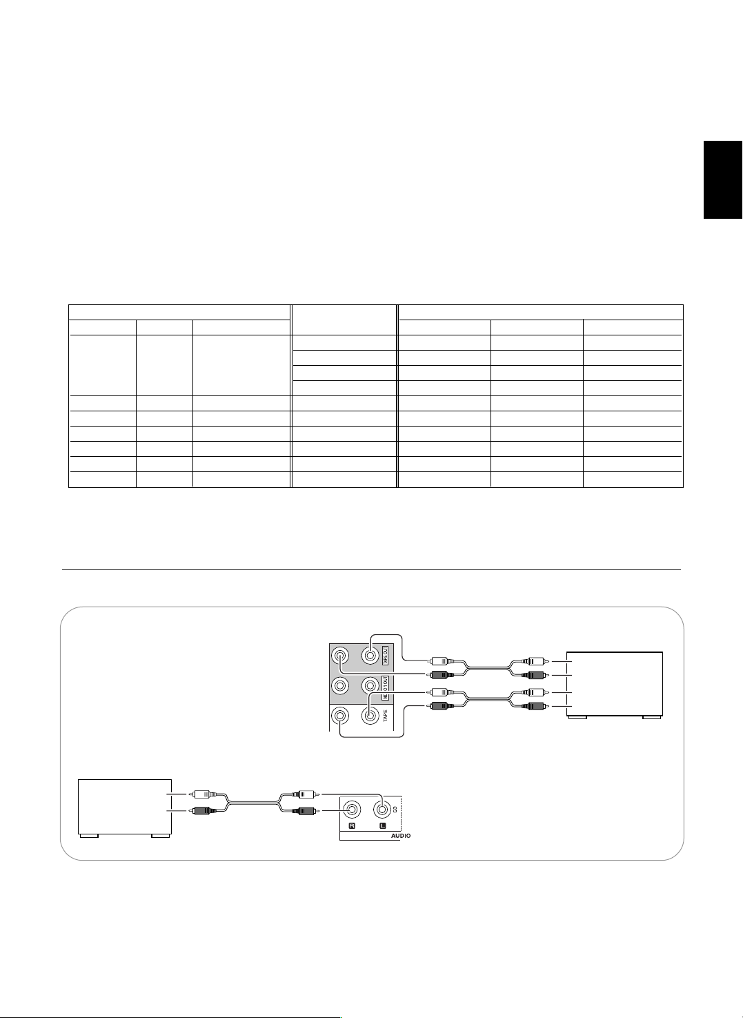
• The TAPE IN/OUT jacks can be connected to audio recording equipment such as a tape deck, an MD recorder, etc.
AUDIO
OUT
L
R
CD
CD player
AUDIO
IN
L
R
AUDIO
OUT
L
R
TAPE
Tape deck,
MD recorder, etc.
3.
CONNECTING AUDIO COMPONENTS
ENGLISH
ENGLISH
8
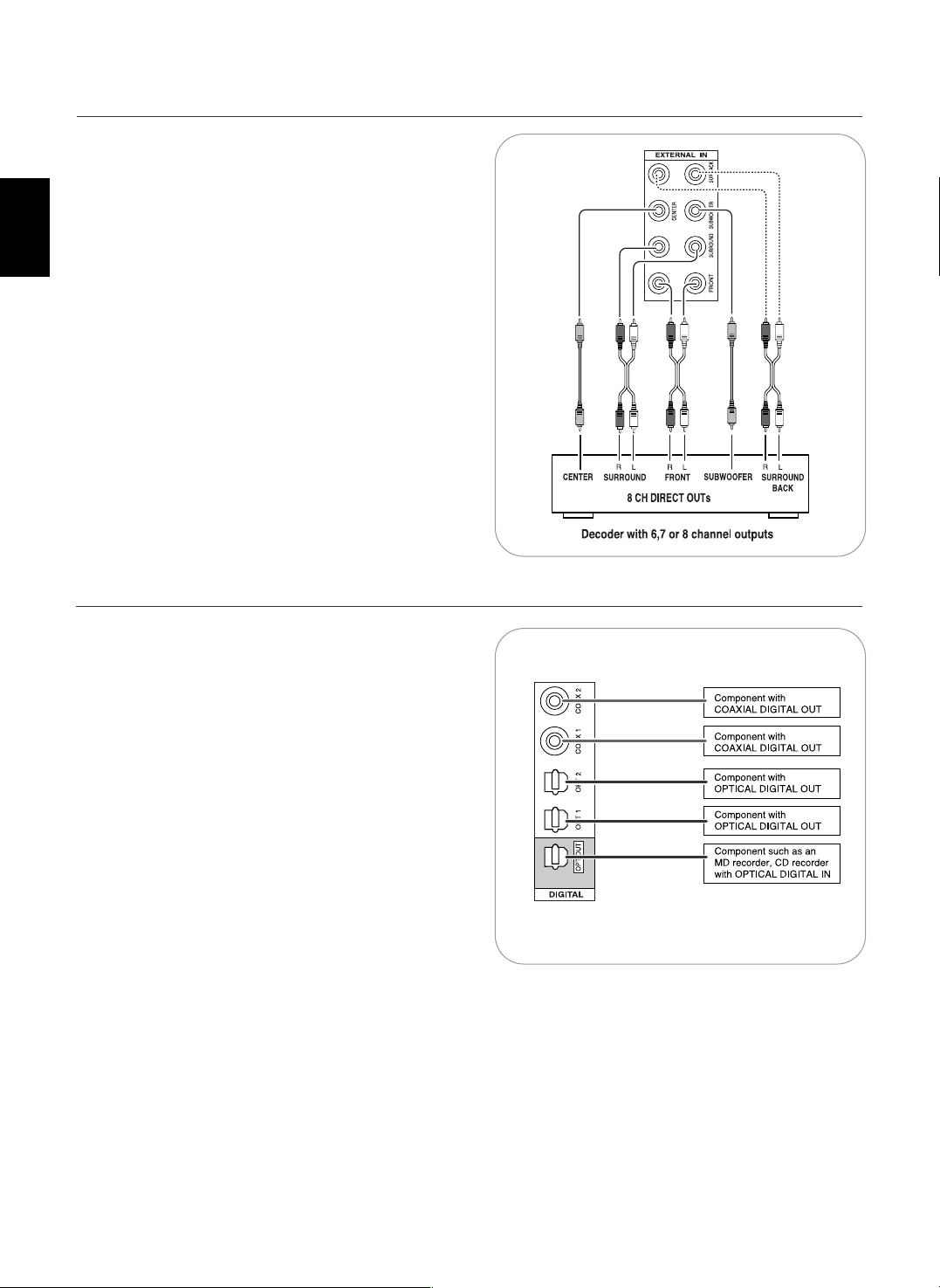
• Use these jacks to connect the corresponding outputs of a
DVD player or external decoder, etc. that has 6, 7 or 8
channel analog audio outputs
• In case of 6 or 7 channel outputs, do not connect both of the
SURROUND BACK L and R inputs or the SURROUND BACK
R input of this unit. (For details, refer to the operating
instructions of the component to be connected.)
4. CONNECTING EXTERNAL INS
• The OPTICAL and the COAXIAL DIGITAL OUTs of the
components that are connected to this unit can be connected
to these DIGITAL INs.
• A digital input should be connected to the components such
as a CD player, LD player, DVD player, etc. capable of
outputting DTS Digital Surround, Dolby Digital or PCM format
digital signals, etc.
• If the component with OPTICAL IN jack is connected to the
OPTICAL OUT jack of this unit, you can record the high
quality sound of CDs, etc. without degradation.
• For details, refer to the operating instructions of the
component connected.
• When making the COAXIAL DIGITAL connection, be sure to
use a 75 Ω COAXIAL cord, not a conventional AUDIO cord.
• All of the commercially available optical fiber cords cannot be
used for the equipment. If there is an optical fiber cord which
cannot be connected to your equipment, consult your dealer
or nearest service organization.
Note :
• Be sure to make either a OPTICAL or a COAXIAL DIGITAL
connection on each component. (You don’t need to do both.)
Digital input default settings
• If you connect the DIGITAL INs to your components, it is easier to do so following the default settings.
• If your DIGITAL connections are different from default settings, your should assign the DIGITAL INs you used with the "When
selecting the DIGITAL IN" procedure on page 39.
• The default settings are as follows :
OPTICAL IN 1 : VIDEO 1, OPTICAL IN 2 : VIDEO 2, COAXIAL IN 1 : CD, COAXIAL IN 2 : AUX.
5. CONNECTING DIGITAL INS AND OUT
9
XM Mini-Tuner system
R
L
R
L
R
L
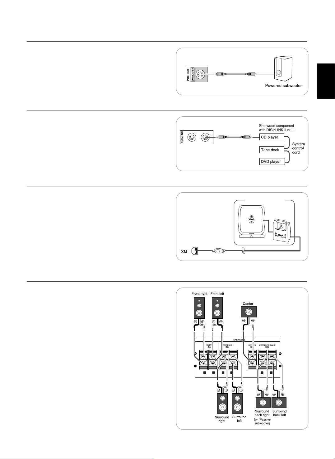
• To emphasize the deep bass sounds, connect a powered
subwoofer.
6. CONNECTING SUBWOOFER PRE OUT
• Connect this jack to the DIGI LINK jack of the external
Sherwood component that uses the DIGI LINK II or III remote
control system.
Note :
• The DIGI LINK operation may not work on some Sherwood
components.
7. CONNECTING DIGI-LINK
• Connect the XM terminal to the XM Mini-Tuner system (sold
separately).
• Position the XM Mini-Tuner system near a south-facing
window to receive the best signal.
When making connections, also refer to the operating
instructions of the XM Mini-Tuner system.
• For the best reception, check the signal strength of the XM radio
signal with using signal strength display mode, then adjust the
position of the XM Mini-Tuner system until “GOOD” is displayed.
(For details, refer to “Displaying XM information” on page 30.)
• To listen to XM Satellite Radio, refer to “XM Satellite Radio
(only for North America)” on page 28.
8. CONNECTING XM (only for North America)
• Be sure to connect speakers firmly and correctly according to
the channel (left and right) and the polarity (+ and -). If the
connections are faulty, no sound will be heard from the
speakers, and if the polarity of the speaker connection is
incorrect, the sound will be unnatural and lack bass.
• For installing the speakers, refer to "Speaker placement" on
page 10.
• After installing the speakers, first adjust the speaker settings
according to your environment and speaker layout. (For details,
refer to "SETTING THE SPEAKER SETUP" on page 41.)
Surround back speakers
• When using only one surround back speaker, you should
connect it to SURROUND BACK LEFT channel.
In this case, you can connect a subwoofer without built-in
amplifier to the SURROUND BACK RIGHT channel. (For details,
refer to “When selecting the AMP ASSIGN” on page 37.)
Caution :
• Be sure to use the speakers with the impedance of 6 ohms or
above.
• Do not let the bare speaker wires touch each other or any
metal part of this unit. This could damage this unit and/or the
speakers.
9.
CONNECTING SPEAKERS
ENGLISH
ENGLISH
10
• These outlets are switched on(power-on mode) and
off(standby mode) according to power control as
follows(Maximum total capacity is 120 W (1 A)).
Standby mode - Switched AC outlet off
Power-on mode - Switched AC outlet on
10. SWITCHED AC OUTLETS
• Plug this cord into a wall AC outlet.
11.
AC INPUT CORD
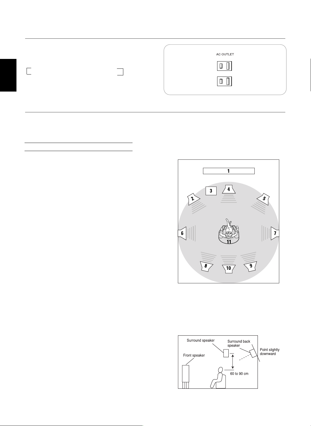
Ideal speaker placement varies depending on the size of your
room and the wall coverings, etc. The typical example of
speaker placement and recommendations are as follows :
■■
Front left and right speakers and center speaker
• Place the front speakers with their front surfaces as flush with
TV or monitor screen as possible.
• Place the center speaker between the front left and right
speakers and no further from the listening position than the
front speakers.
• Place each speaker so that sound is aimed at the location of
the listener’s ears when at the main listening position.
■■
Surround left and right speakers
• Place the surround speakers approximately 1 meter (40
inches) above the ear level of a seated listener on the direct
left and right of them or slightly behind.
■■
Surround back left and right speakers
• Place the surround back speakers at the back facing the front
at a narrower distance than front speakers.
• When using a single surround back speaker, place it at the
rear center facing the front at a slightly higher position (0 to
20 cm) than the surround speakers.
• We recommend installing the surround back speaker(s) at a
slightly downward facing angle. This effectively prevents the
surround back channel signals from reflecting off the TV or
screen at the front center, resulting in interference and
making the sense of movement from the front to the back
less sharp.
■■
Subwoofer
• The subwoofer reproduces powerful deep bass sounds.
Place a subwoofer anywhere in the front as desired.
Notes :
• When using a conventional TV, to avoid interference with the
TV picture, use only magnetically shielded front left and right
and center speakers.
• To obtain the best surround effects, the speakers except the
subwoofer should be full range speakers.
Speaker placement
1. TV or screen
2. Front left speaker
3. Subwoofer
4. Center speaker
5. Front right speaker
6. Surround left speaker
7. Surround right speaker
8. Surround back left speaker
9. Surround back right speaker
10. Surround center speaker
11. Listening position
11
FLUORESCENT DISPLAY
Front Panel Controls
MEMO/ENTER PRESETTUNE
VIDEO 3
XM
D/A MODEDISPLAY SETUP CH. LEVEL CONTROL
AUDIO/VIDEO RECEIVER
RD-7502
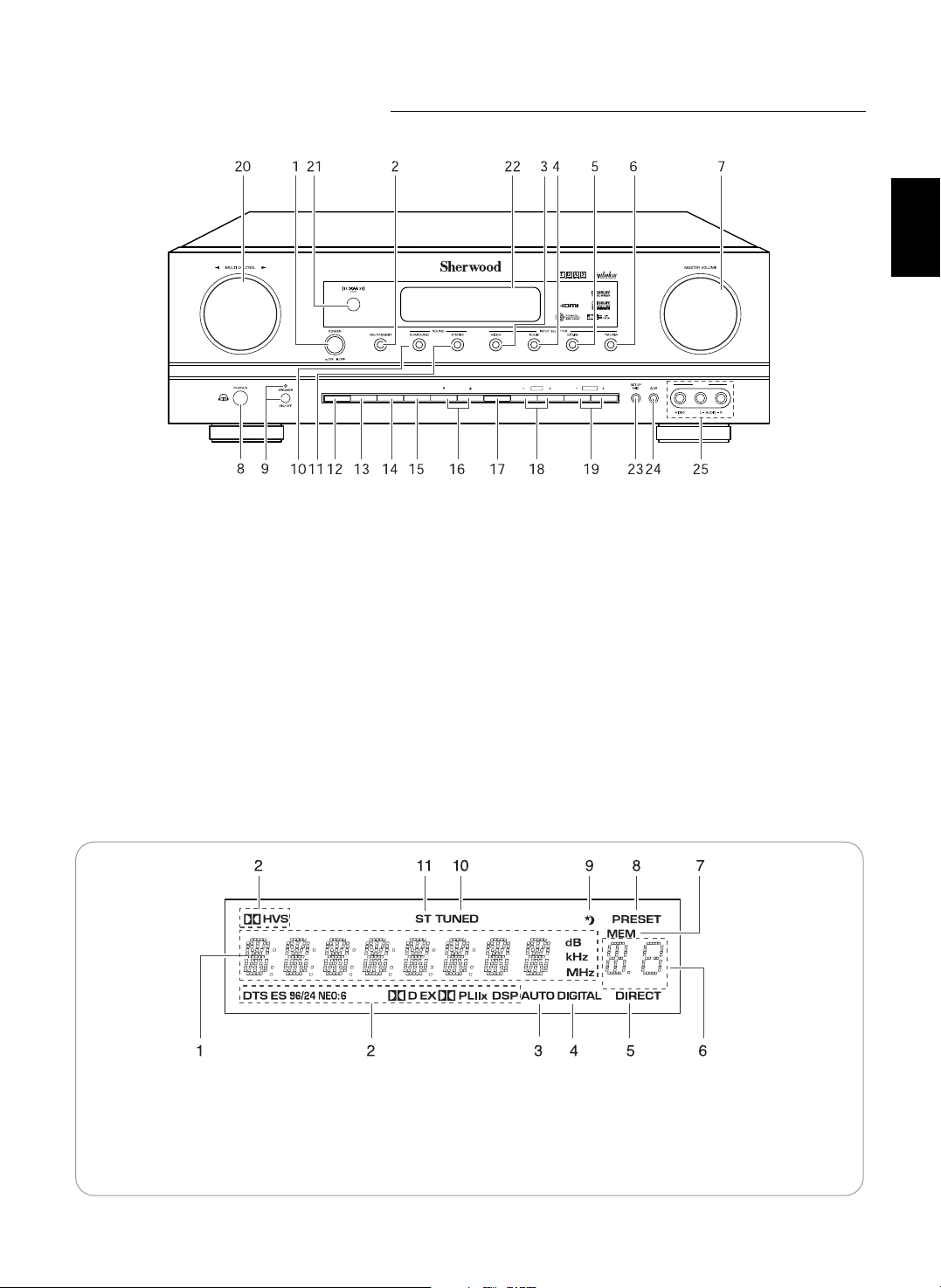
1. POWER switch
2. POWER ON/STANDBY button/indicator
3. VIDEO INPUT SELECTOR button
4. AUDIO INPUT SELECTOR button
5. EXTERNAL IN button
6. BAND button
7. MASTER VOLUME CONTROL knob
8. HEADPHONE jack
9. SPEAKER button/indicator
10. SURROUND MODE button
11. STEREO button
12. DISPLAY button
13. DIGITAL / ANALOG MODE button
14. SETUP button
15. CHANNEL LEVEL button
16. CONTROL UP/DOWN(▲/▼) buttons
17. MEMORY/ENTER button
18. TUNING UP/DOWN(+/-) buttons
19. PRESET UP/DOWN(+/-) buttons
20. MULTI CONTROL knob
21. REMOTE SENSOR
22. FLUORESCENT DISPLAY
For details, see below.
23. SETUP MIC jack
For details, see next page.
24. AUX IN jack
For details, see next page.
25. VIDEO 3 IN jacks
For details, see next page.
1. Input, frequency, volume level, operating information, etc.
2. Surround mode indicators
3. AUTO indicator
4. DIGITAL INPUT indicator
5. DIRECT indicator
6. Preset number, sleep time display
7. MEMORY indicator
8. PRESET indicator
9. SLEEP indicator
10. TUNED indicator
11. STEREO indicator
ENGLISH
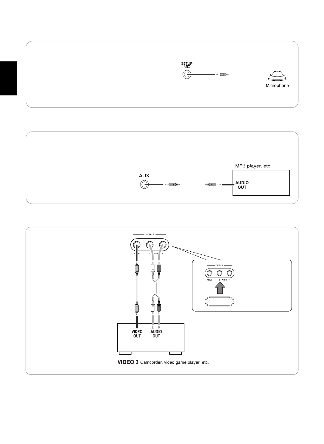
VIDEO 3 IN JACKS
When not using the
VIDEO 3 IN jacks,
cover these jacks
with the supplied cap.
• The VIDEO 3 IN jacks may be also
connected to an additional video
component such as a camcorder,
video game player, etc.
• To use Auto Setup function, connect the supplied microphone
to the SETUP MIC jack.(For details, refer to "When selecting
the AUTO SETUP" on page 41.)
Notes:
• Because the microphone for Auto Setup is designed for use
with this receiver, do not use a microphone other than the one
supplied with this receiver.
• After you have completed the auto setup procedure,
disconnect the microphone.
SETUP MIC JACK
• The AUX IN jack can be connected to an additional audio
component such as an MP3 player, etc.
Note:
• When connecting this jack to an MP3 player, etc., you should
use the stereo mini cord, not a mono mini cord.
AUX IN JACK
ENGLISH
12
13
ENGLISH
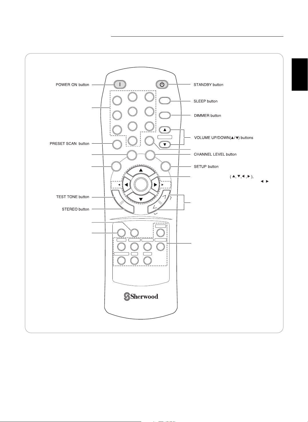
Remote Controls
POWER ON
STANDBY
SLEEP
1
2
3
4
5
6
7
8
0
9
DIMMER
DISPLAY
SEL SEL
P.SCAN
CH.LEVEL
MUTE
D/A MODE
SETUP
TONE
SOUND
PARAMETER
REMOTE CONTROL RC-110
ENTER
VOLUME
VIDEO 1TAPE VIDEO 2 VIDEO 3
EXT.IN
CD
FM/AM/XM
AUX
T
E
S
T
S
T
E
R
E
O
S
U
R
R
O
U
N
D
S
E
A
R
C
H
M
O
D
E
DISPLAY button
DIGITAL/ANALOG MODE
button
CUSOR CONTROL
ENTER</SEARCH MODE, SELECT / >
buttons
• The functions in "< >" are regional option
for North America.
SURROUND MODE UP/DOWN(>/<)
buttons
MUTE button
INPUT SELECTOR buttons
SOUND PARAMETER button
TONE MODE button
NUMERIC (1~0) buttons
ENGLISH
14
LOADING BATTERIES
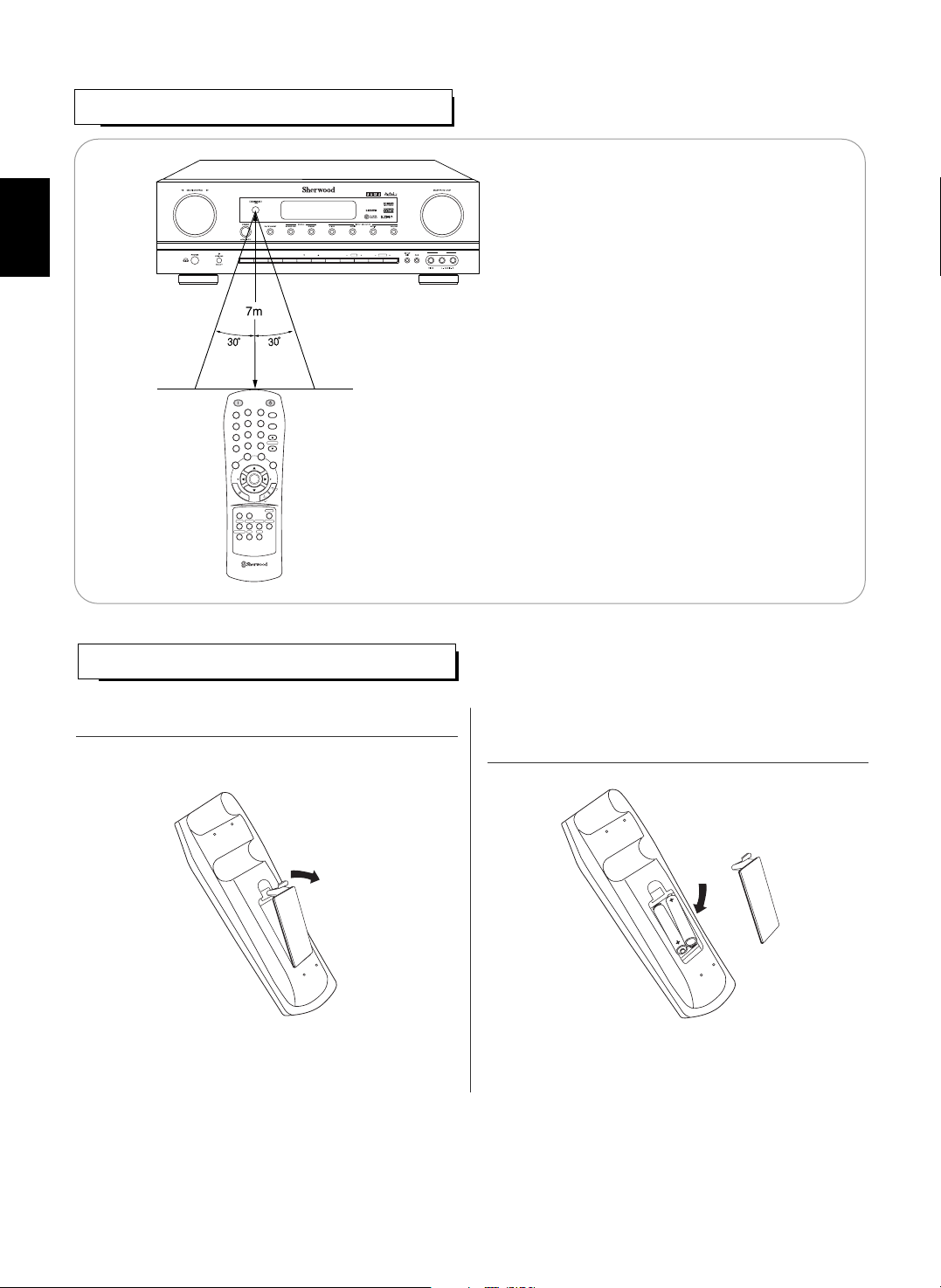
REMOTE CONTROL OPERATION RANGE
• Use the remote control unit within a range of
about 7 meters (23 feet) and angles of up to 30
degrees aiming at the remote sensor.
• Remove the batteries when they are not used for a long
time.
• Do not use the rechargeable batteries(Ni-Cd type).
MEMO/ENTER PRESETTUNE
VIDEO 3
XM
D/A MODEDISPLAY SETUP CH. LEVEL CONTROL
AUDIO/VIDEO RECEIVER
RD-7502
POWER ON
STANDBY
SLEEP
1
2
3
4
5
6
7
8
0
9
DIMMER
DISPLAY
SEL SEL
P.SCAN
CH.LEVEL
MUTE
D/A MODE
SETUP
TONE
SOUND
PARAMETER
REMOTE CONTROL RC-110
ENTER
VOLUME
VIDEO 1TAPE VIDEO 2VIDEO 3
EXT.IN
CD
FM/AM/XM
AUX
T
E
S
T
S
T
E
R
E
O
S
U
R
R
O
U
N
D
S
E
A
R
C
H
M
O
D
E
1. Remove the cover. 2. Load two batteries("AAA" size, 1.5V) matching the
polarity.
15
LISTENING TO A PROGRAM SOURCE
Operations
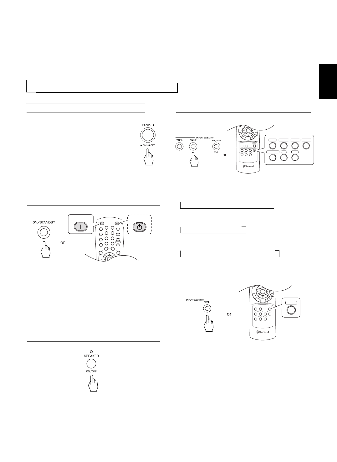
Before operation
• Enter the standby mode.
• The POWER ON/STANDBY button lights up .
This means that the receiver is not
disconnected from the AC mains and a small
amount of current is retained to support the
operation readiness.
• To switch the power off, push the POWER
switch again.
• Then the power is cut off and the POWER ON
/ STANDBY button goes off.
• Each time the "VIDEO" button on the front panel is
pressed, the input source changes as follows:
→ VIDEO 1 → VIDEO 2 → VIDEO 3
• Each time the "AUDIO" button on the front panel is
pressed, the input source changes as follows:
→ CD → AUX → TAPE
• Each time the BAND button is pressed, the band
changes as follows;
→ FM ST → FM MONO → AM → XM
When selecting the EXTERNAL IN as desired,
• Depending on the surround back speaker setting, "EXT
IN" is displayed and 8(/7/6) separate analog signals
from the component connected to this input pass
through the tone and volume circuits only and can be
heard from your speakers.
• Press the EXTERNAL IN button or select the desired
input source to cancel the external in function.
• These analog signals can be heard only, not
recorded.
SEL SEL
TONE
SOUND
PARAMETER
REMOTE CONTROL RC-110
ENTER
VIDEO 1TAPE VIDEO 2 VIDEO 3
EXT.IN
CD
FM/AM/XM
AUX
T
E
S
T
S
T
E
R
E
O
S
U
R
R
O
U
N
D
S
E
A
R
C
H
M
O
D
E
EXT.IN
DISPLAY
SEL SEL
CH.LEVELD/A MODE
SETUP
TONE
SOUND
PARAMETER
REMOTE CONTROL RC-110
ENTER
VIDEO 1TAPE VIDEO 2 VIDEO 3
EXT.IN
CD
FM/AM/XM
AUX
T
E
S
T
S
T
E
R
E
O
S
U
R
R
O
U
N
D
S
E
A
R
C
H
M
O
D
E
VIDEO 1TAPE VIDEO 2 VIDEO 3
CD
FM/AM/XM
AUX
Notes:
• Before operating this receiver, first set this unit as desired for optimum performance, doing the system setup procedures. (For
details, refer to “System Setup” on page 34)
POWER ON
STANDBY
SLEEP
1
2
3
4
5
6
7
8
0
9
DIMMER
DISPLAY
SEL SEL
P.SCAN
CH.LEVEL
MUTE
D/A MODE
SETUP
ENTER
VOLUME
T
E
S
POWER ON
STANDBY
• Each time the POWER ON/STANDBY button on the
front panel is pressed, the receiver is turned on to enter
the operating mode or off to enter the standby mode.
• On the remote control, press the POWER ON button to
enter the operating mode or press the STANDBY button
to enter the standby mode.
• In the standby mode, if the INPUT SELECTOR button is
pressed, the receiver is turned on automatically and the
desired input is selected.
1. In the standby mode, turn the power on.
2. Switch the speakers on.
3. Select the desired input source.
• Then the SPEAKER indicator lights up and the sound
can be heard from the speakers connected to the
speaker terminals.
• When using the headphone for private listening, press
the SPEAKER button again to switch the speakers off.
ENGLISH
ENGLISH
16
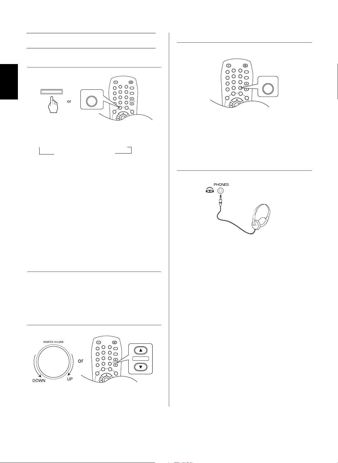
When CD, AUX, VIDEO 1~2 is selected as an
input source
• "MUTE" will flicker.
• To resume the previous sound level, press it again.
• Each time this button is pressed, the corresponding
input is selected as follows:
→ A(nalog) → o(ptical) 1 → o(ptical) 2
c(oaxial) 2 ← c(oaxial) 1 ←
Notes :
• When TUNER, TAPE, EXTERNAL IN or VIDEO 3 is
selected as an input source, the analog input is selected
automatically.
• When the selected digital input is not connected, the
"DIGITAL" indicator flickers and the analog input is
automatically selected.
• The selected digital or analog input is automatically
assigned to the corresponding input source on the
INPUT setup menu. (For details, refer to "SETTING
THE INPUT" on page 39.)
• The sound from the component connected to the
selected digital input can be heard regardless of the
selected input source.
4. Select the digital or analog input connected as desired.
5. Operate the selected component for playback.
6. Adjust the (overall) volume.
7. To mute the sound.
• Ensure that the SPEAKER button is set to off.
• Depending on the signal format which is being input, you
can listen in different Dolby Headphone modes, stereo
mode, etc. (For details, refer to "Listening in a Dolby
Headphone mode" on page 21).
• When the EXTERNAL IN is selected as an input source,
only front left and front right channel signals can be
reproduced through the headphones.
8. To listen with the headphones.
• When playing back the program sources with surround
sound, refer to "ENJOYING SURROUND SOUND" on
page 20.
POWER ON
STANDBY
SLEEP
1
2
3
4
5
6
7
8
0
9
DIMMER
DISPLAY
SEL SEL
P.SCAN
CH.LEVEL
MUTE
D/A MODE
SETUP
ENTER
VOLUME
T
E
S
T
S
T
E
R
E
O
R
O
U
N
D
S
E
A
R
C
H
M
O
D
E
D/A MODE
D/A MODE
POWER ON
STANDBY
SLEEP
1
2
3
4
5
6
7
8
0
9
DIMMER
DISPLAY
SEL SEL
P.SCAN
CH.LEVEL
MUTE
D/A MODE
SETUP
ENTER
VOLUME
T
E
S
T
S
T
E
R
O
U
N
D
S
E
A
R
C
H
M
O
D
E
VOLUME
POWER ON
STANDBY
SLEEP
1
2
3
4
5
6
7
8
0
9
DIMMER
DISPLAY
SEL SEL
P.SCAN
CH.LEVEL
MUTE
D/A MODE
SETUP
ENTER
VOLUME
T
E
S
T
MUTE
17
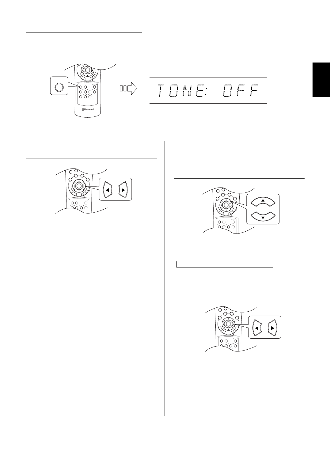
Adjusting the tone (bass and treble)
• The tone mode is displayed for several seconds.
Note : When the digital signals from DTS, Dolby Digital program
sources are input or the EXTERNAL IN is selected can
listen to a program source without the tone effect.
When the “TONE” is set to ON to adjust the
tone (bass and treble).
• The tone level can be adjusted within the range of -10 ~
+10 dB.
• In general, we recommend the bass and treble to be
adjusted to 0 dB (flat level).
• Extreme settings at high volume may damage your
speakers.
• To complete tone adjustment, repeat the above steps 11
and 12.
• If the tone display disappears, start from the step 9
again.
7
8
0
9
DISPLAY
SEL SEL
P.SCAN
CH.LEVEL
MUTE
D/A MODE
SETUP
TONE
SOUND
PARAMETER
ENTER
VOLUME
VIDEO 1TAPE VIDEO 2 VIDEO 3
EXT.IN
CD
FM/AM/XM
AUX
T
E
S
T
S
T
E
R
E
O
S
U
R
R
O
U
N
D
S
E
A
R
C
H
M
O
D
E
7
8
0
9
DISPLAY
SEL SEL
P.SCAN
CH.LEVEL
MUTE
D/A MODE
SETUP
TONE
SOUND
PARAMETER
ENTER
VOLUME
VIDEO 1TAPE VIDEO 2 VIDEO 3
EXT.IN
CD
FM/AM/XM
AUX
T
E
S
T
S
T
E
R
E
O
S
U
R
R
O
U
N
D
S
E
A
R
C
H
M
O
D
E
7
8
0
9
DISPLAY
SEL SEL
P.SCAN
CH.LEVEL
MUTE
D/A MODE
SETUP
TONE
SOUND
PARAMETER
ENTER
VOLUME
VIDEO 1TAPE VIDEO 2 VIDEO 3
EXT.IN
CD
FM/AM/XM
AUX
T
E
S
T
S
T
E
R
E
O
S
U
R
R
O
U
N
D
S
E
A
R
C
H
M
O
D
E
• Each time these buttons are pressed, the tone mode is
selected as follows:
OFF : To listen to a program source without the tone
effect. (“DIRECT” indicator lights up.)
ON : To adjust the tone for your taste.
(“DIRECT” indicator goes off.)
• Each time these buttons are pressed, the tone is
selected as follows:
BASS TRBL(treble) TONE ON
9. Enter the tone mode.
10. Press the CURSOR LEFT(◀)/RIGHT(▶) buttons to
select the desired tone mode.
11. Press the CURSOR UP(▲)/DOWN(▼) buttons to
select the desired tone.
12. Press the CURSOR LEFT(◀)/RIGHT(▶) buttons to
adjust the selected tone as desired.
DISPLAY
SEL SEL
SETUP
TONE
SOUND
PARAMETER
REMOTE CONTROL RC-110
ENTER
VIDEO 1TAPE VIDEO 2 VIDEO 3
EXT.IN
CD
FM/AM/XM
AUX
T
E
S
T
S
T
E
R
E
O
S
U
R
R
O
U
N
D
S
E
A
R
C
H
M
O
D
E
TONE
ENGLISH
 Loading...