


ENGLISH
U N P A C K I N G A N D

Congratulations on Your Purchase!
Your new high fidelity pre amplifier is designed to deliver maximum enjoyment and years of trouble free service. Please take a few moments to read this manual thoroughly. It will explain the features and operation of your unit and help ensure a trouble free installation. Please unpack your unit carefully. We recommend that you save the carton and packing material. They will be helpful if you ever need to move your unit and may be required if you ever need to return it for service. Your unit is designed to be placed in a horizontal position and it is important to allow at least two inches of space behind your unit for adequate ventilation and cabling convenience.
To avoid damage, never place the unit near radiators, in front of heating vents, in direct sunlight, or in excessively humid or dusty locations. Connect your complementary components as illustrated in the following section.
CAUTION |
RISK OF ELECTRIC SHOCK |
DO NOT OPEN |
CAUTION : TO REDUCE THE RISK OF |
ELECTRIC SHOCK, DO NOT |
REMOVE COVER (OR BACK). |
NO USER-SERVICEABLE PARTS |
INSIDE. REFER SERVICING TO |
QUALIFIED SERVICE PERSONNEL. |
This symbol is intended to alert the user to the presence of uninsulated "dangerous voltage" within the product's enclosure that may be of sufficient magnitude to constitute a risk of electric shock to persons.
This symbol is intended to alert the user to the presence of important operating and maintenance (servicing) instructions in the literature accompanying the appliance.
WARNING
To reduce the risk of fire or electric shock, do not expose this appliance to rain or moisture.
Caution : Do not block ventilation openings or stack other equipment on the top.
FOR U.S.A.
 Note to CATV System Installer: This reminder is provided to call the CATV system installer's attention to Article 820-40 of the NEC that provides guidelines for proper grounding and, in particular, specifies that the cable ground shall be connected to the grounding system of the building, as close to the point of cable entry as practical.
 FCC INFORMATION
This equipment has been tested and found to comply with the limits for a Class B digital device, pursuant to Part 15 of the FCC Rules. These limits are designed to provide reasonable protection against harmful interference in a residential installation. This equipment generates, uses and can radiate radio frequency energy and, if not installed and used in accordance with the instructions, may cause harmful interference to radio communications. However, there is no guarantee that interference will not occur in a particular installation. If this equipment does cause harmful interference to radio or television reception, which can be determined by turning the equipment off and on, the user is encouraged to try to correct the interference by one or more of the following measures:
 Reorient or relocate the receiving antenna.
 Increase the separation between the equipment and receiver.
 Connect the equipment into an outlet on a circuit different from that to which the receiver is connected.
 Consult the dealer or an experienced radio/TV technician for help.
CAUTION: Any changes or modifications in
construction of this device which are not expressly approved by the party responsible for compliance could void the user's authority to operate the equipment.
2

READ THIS BEFORE OPERATING 

FOR YOUR SAFETY
Units shipped to the U.S.A. and Canada are designed for operation on 120 V AC only.
Safety precaution with use of a polarized AC plug. However, some products may be supplied with a nonpolarized plug.
CAUTION : To prevent electric shock, match wide
blade of plug to wide slot, fully insert.
ATTENTION : Pour eviter les choc electriques,
introduire la lame la plug large de la borne
FOR YOUR SAFETY
Units shipped to Australia are designed for operation on 240 V AC only.
To ensure safe operation, the three-pin plug supplied must be inserted only into a standard threepin power point which is effectively earthed through the normal household wiring. Extension cords used with the equipment must be three-core and be correctly wired to provide connection to earth. Improper extension cords are a major cause of fatalities. The fact that the equipment operates satisfactorily does not imply that the power point is earthed and that the installation is completely safe. For your safety, if in any doubt about the effective earthing of the power point, consult a qualified electrician.
PAN-EUROPEAN UNIFIED VOLTAGE
All units are suitable for use on supplies 230-240 V AC.
FOR YOUR SAFETY
Units shipped to countries other than the above countries are equipped with an AC voltage selector
switch on the rear panel. Refer to the following paragraph for the proper setting of this switch.
AC VOLTAGE SELECTION
This unit operates on 110-220V AC. The AC voltage selector switch on the rear panel is set to the voltage that prevails in the area to which the unit is shipped. Before connecting the power cord to your AC outlet, make sure that the setting position of this switch matches your line voltage. If not, it must be set to your voltage in accordance with the following direction.
AC voltage selector switch
AC110V220 V |
ACAC110220V |
Move switch lever to match your line voltage with a small screwdriver or other pointed tool.
ENGLISH
3

ENGLISH
CONTENTS
Introduction |
|
UNPACKING AND INSTALLATION |
2 |
READ THIS BEFORE OPERATING YOUR UNIT |
3 |
System Connections |
5 |
Front Panel Controls |
8 |
Universal Remote Control |
|
DIGI LINK SYSTEM REMOTE CONTROLS |
9 |
OPERATING COMPONENTS WITH REMOTE CONTROL |
11 |
REMOTE CONTROL OPERATION RANGE |
11 |
LOADING BATTERIES |
11 |
ENTERING A SET-UP CODE |
12 |
Operations |
|
LISTENING TO A PROGRAM SOURCE |
13 |
SURROUND SOUND |
16 |
ENJOYING SURROUND SOUND |
17 |
LISTENING TO RADIO BROADCASTS |
22 |
LISTENING TO RDS BROADCASTS (FM only) |
|
(Additional Function for AVP-9080 RDS Tuner Only) |
24 |
AUDIO RECORDING |
26 |
OTHER FUNCTIONS |
27 |
Using the OSD |
|
CURRENT STATUS DISPLAY |
29 |
MENU SCREEN |
30 |
RECORDING WITH VIDEO 1 OR VIDEO 2 USING MENU SCREEN |
33 |
Troubleshooting Guide |
35 |
Specifications |
36 |
4
 Do not plug the AC input cord into the wall AC outlet until all connections are completed.
 Be sure to connect the white RCA cord to the L (left) and the red RCA cord to the R (right) jacks when making audio connections.
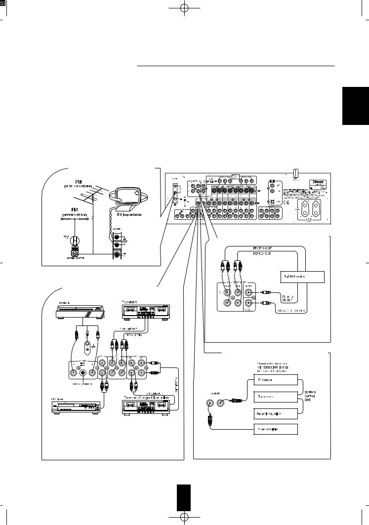
 Change the position of the FM indoor antenna until you get the best reception of your favorite FM stations.
 A 75 Ω outdoor FM antenna may be used to further improve the reception. Disconnect the indoor antenna before replacing it with the outdoor one.
 Place the AM loop antenna as far as possible from the receiver, TV set, speaker wires and the AC input cord. Point it in the direction that offers the best reception.
 If the reception is poor with the AM loop antenna, an AM outdoor antenna can be used in place of the AM loop antenna.
 Make connections firmly and correctly. If not, it can cause loss of sound, noise or damage to the pre amplifier.
 If the electricity fails or the AC input cord is left unplugged for about 2 weeks, the memorized contents will be cleared. Should this happen, memorize them again.
 CONNECTING ANTENNAS
 CONNECTING 6-CH DIRECT INPUTS
 CONNECTING AUDIO COMPONENTS
HX-PRO
B A
 Use these jacks to connect the corresponding analog outputs of a separate 6-CH decoder or DVD player with 6-CH output. (For details, see the operator’s manual of the other component.)
HX-PRO
B A
 To select the gain and the input impedance of the phono input circuitry according to the phono cartridge type of the turntable connected, set the MM/MC switch to either
  for MC(moving coil) or
 for MM(moving magnet).
 The TAPE 2 MONITOR IN/OUT jacks may also be connected to the LINE OUT/IN jacks of an optional graphic equalizer.
ENGLISH
5
ENGLISH
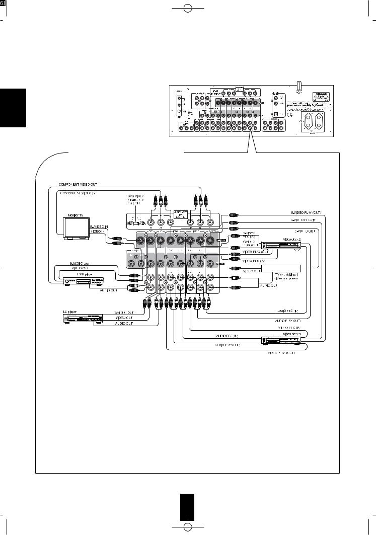
 CONNECTING VIDEO COMPONENTS
 Some video components such as DVD player or TV set, etc. have the COMPONENT VIDEO IN/OUT jacks as well as the S-VIDEO REC/PLAY or the normal VIDEO REC/PLAY jacks.
 When connecting the COMPONENT VIDEO IN jacks of this unit to the corresponding COMPONENT VIDEO OUT jacks of a DVD player respectively, be sure that the DVD VIDEO SELECTOR switch is set to “COMPONENT”. When the COPONENT VIDEO connections are not made, be sure that the DVD VIDEO SELECTOR switch is set to “S-VIDEO/VIDEO”.
Note : When the DVD VIDEO SELECTOR switch is set to “COMPONENT”, a signal input into the S-VIDEO PLAY jack or the normal VIDEO PLAY jack of DVD will not be output in the MONITOR S-VIDEO jack or the MONITOR normal VIDEO jack.
 A signal input into the S-VIDEO PLAY jack will be output in only the S-VIDEO REC jack and a signal input into the normal VIDEO PLAY(or the COMPONENT VIDEO IN) jack will be also output in only its own VIDEO REC (or OUT) jack.
 However, the video signal will be output in the MONITOR VIDEO jack according to the video signal priority (“COMPONENT”
  “S”
“S”
 “normal”) as follows:
 For better picture quality, use the S-VIDEO jacks to connect video components with the S-VIDEO REC(IN)/PLAY(OUT) jacks. When using a video component with the COMPONENT VIDEO IN/OUT jacks, use the COMPONENT VIDEO jacks.
 A signal input into the S-VIDEO PLAY jack will be output in both the MONITOR S-VIDEO jack and the MONITOR normal VIDEO jack and a signal input into the normal VIDEO PLAY jack will be output in only the MONITOR normal VIDEO jack.


 DVD player, a signal input into the COMPONENT VIDEO IN jack will be output in the COMPONENT VIDEO OUT jack as well as the MONITOR S-VIDEO jack and the MONITOR normal VIDEO jack.
Note : The On Screen Display function is not available when using the COMPONENT VIDEO connections.
6
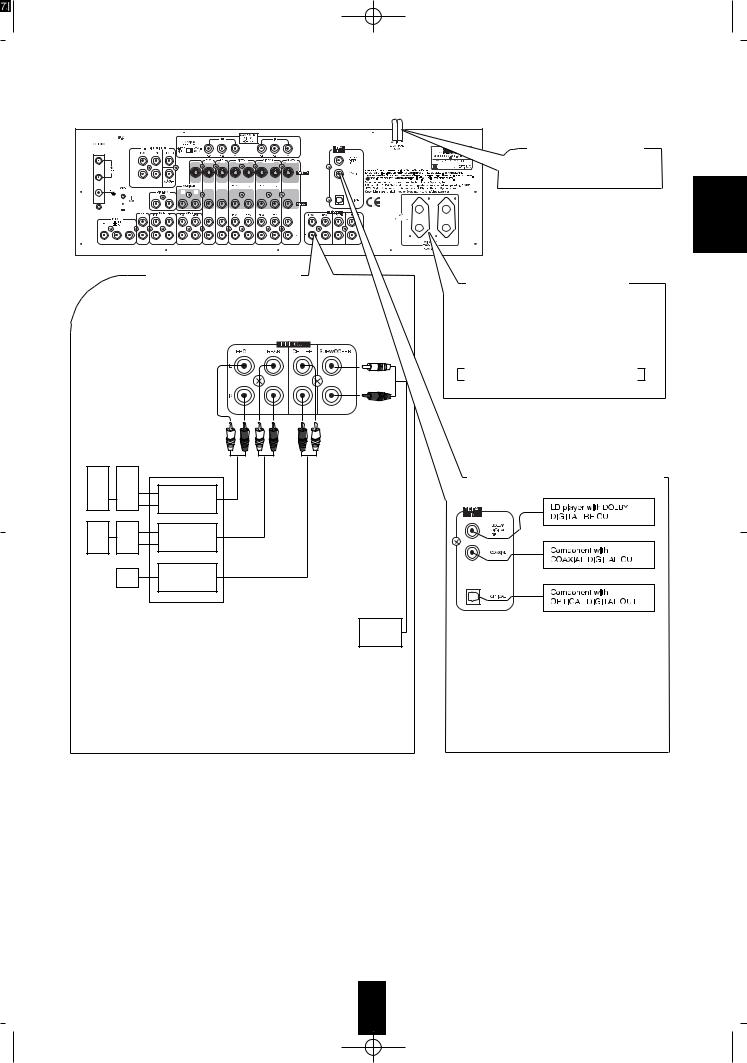
 PRE OUT connections
 Connect the PRE OUT jacks to the power amplifers connected to speakers or to powered speaker respectively.
 We recommand that you use Sherwood power amplifer AM-9080 for 5 channels (front L/R, rear L/R, center) for easy operation and installation.
 Although left and right outputs are offered for CENTER and SUBWOOFER, both channels produce the same signal.
Connect one or both channels as required by the power amplifier or powered subwoofer used.
 AC INPUT CORD
Plug this cord into a wall AC outlet
ENGLISH
 These outlets are switched on (power on mode) and off (standby mode) according to power control as follows: (Maximum total capacity is 100 W)
Standby mode - switched AC outlet off
Power on mode - switched AC outlet on
 CONNECTING DIGITAL INPUTS
 Components such as CD, LD or DVD capable of digital output of DTS Digital Surround, Dolby Digital, PCM or digital RF should be connected to these inputs.
 For details, refer to the operating instructions of the component connected.
 When making the COAXIAL DIGITAL connection, be sure to use a 75Ω COAXIAL cord, not a conventional AUDIO cord.
7
ENGLISH
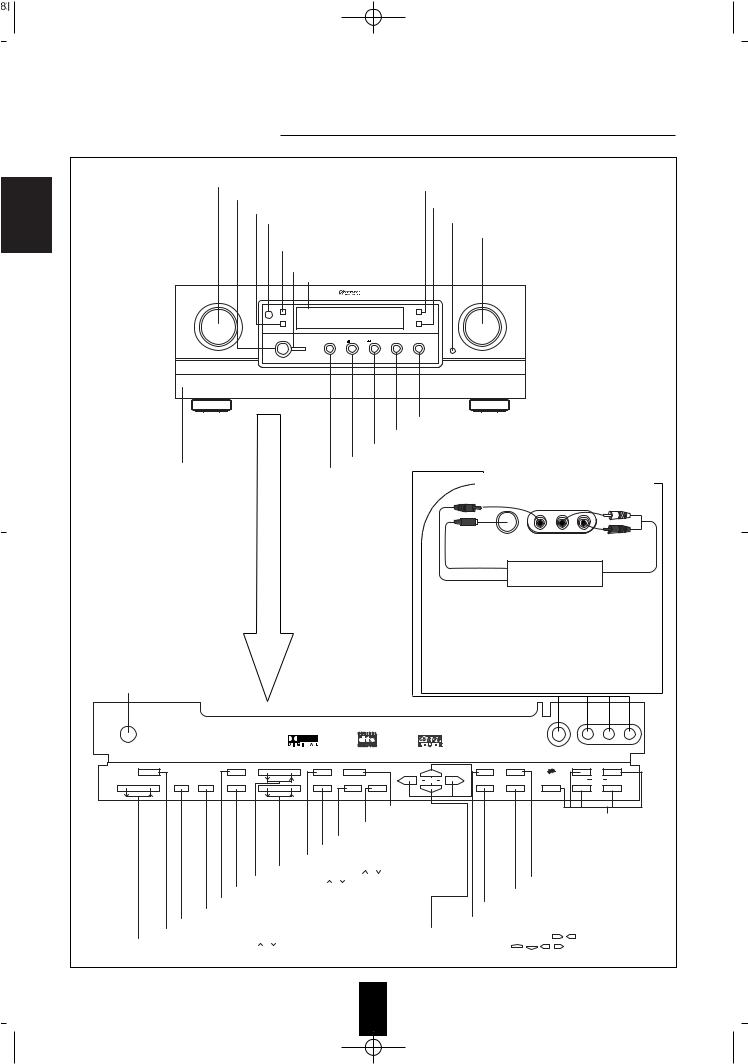
INPUT SELECTOR KNOB
TONE DIRECT BUTTON/INDICATOR
POWER SWITCH
DIGITAL INPUT BUTTON/INDICATOR |
DYNAMIC RANGE BUTTON/INDICATOR |
||
DOOR OPEN BUTTON |
|||
REMOTE SENSOR |
|
||
|
|
||
TAPE 2 MONITOR |
MASTER VOLUME KNOB |
||
BUTTON/INDICATOR |
|
||
STANDBY |
|
|
|
BUTTON/INDICATOR |
|
||
FLUORESCENT DISPLAY |
|
||
INPUT SELECTOR |
|
MASTER VOLUME |
|
TAPE 2 MONITOR |
|
TONE DIRECT |
|
DIGITAL INPUT |
|
DYNAMIC RANGE |
|
POWER |
|
|
|
ON/OFF |
|
|
|
DTS |
DIGITAL PRO-LOGIC DSP MODE |
STEREO |
|
STANDBY |
|
DOOR OPEN |
|
A/V TUNER PRE AMPLIFIER AVP-9080RDS |
STEREO (SURROUND OFF) BUTTON
DSP MODE BUTTON
DOLBY PRO LOGIC BUTTON
DOLBY DIGITAL BUTTON
PANEL DOOR
DTS BUTTON
VIDEO3/CAMCORDER INPUT JACKS
|
S.VIDEO VIDEO3/CAMCORDER INPUT |
||
hen |
VIDEO |
L - AUDIO - R |
|
Additional video component |
|||
open |
|||
S_VIDEO OUT |
AUDIO OUT |
||
button |
|
||
VIDEO OUT
 The VIDEO 3/CAMCORDER INPUT jacks may be also connected to an additional video component such as a camcorder, a video deck or a video game player, etc.
 Use the S-VIDEO jack to make connection to video component with the S-VIDEO OUT jack.
A signal input into the S-VIDEO jack will be output in both the MONITOR S-VIDEO jack and the MONITOR normal VIDEO jack and a signal input into the normal VIDEO jack
will be output in only the MONITOR normal VIDEO jack.
HEADPHONE JACK
PHONES |
|
|
|
|
|
|
|
|
S.VIDEO |
VIDEO3/CAMCORDER INPUT |
||
|
|
|
|
|
|
|
|
|
|
|
VIDEO |
L - AUDIO - R |
|
|
|
|
|
PRESET/TUNING |
PRESET/TUNING |
|
|
|
|
|
|
CH SELECTOR |
TEST TONE |
BASS |
TONE MODE |
6-CH DIRECT |
|
|
T/P MODE |
BAND |
R D S/E O N |
|
PTY EON |
TA |
|
OSD |
|
|
|||||||||
LEVEL |
DELAY TIME ADJUST SPEAKER MODE |
TREBLE |
FLAT |
VIDEO LABELS |
MEMORY/ENTER |
|
ON SCREEN |
FM MODE |
SEARCH |
|
DISPLAY |
PTY SEL |
|
|
|
|
|
6 CH DIRECT BUTTON |
|
|
|
|
RDS BUTTONS |
||
|
|
|
|
MEMORY / ENTER BUTTON |
|
|
|
|
||||
|
|
|
|
|
|
|
|
(AVP-9080RDS ONLY) |
||||
|
|
|
|
VIDEO LABELS BUTTON |
|
|
|
|
Refer to "Additional function |
|||
|
|
|
TONE FLAT BUTTON |
|
|
|
|
|
for AVP-9080RDS |
|||
|
|
|
|
|
|
|
|
Tuner Only" on page 24. |
||||
|
|
|
TONE MODE BUTTON |
|
|
|
|
|
||||
|
|
|
|
|
|
|
|
|
|
|||
|
|
TREBLE UP / DOWN ( |
/ ) BUTTONS |
|
|
|
|
|
|
|||
|
BASS UP / DOWN ( |
/ ) BUTTONS |
|
|
|
BAND BUTTON |
|
|||||
|
SPEAKER MODE BUTTON |
|
|
|
FM MODE BUTTON |
|
||||||
|
TEST TONE BUTTON |
|
|
|
|
|
|
|||||
|
|
|
|
|
ON SCREEN BUTTON |
|
||||||
|
DELAY ADJUST BUTTON |
|
|
|
|
|
||||||
|
|
|
|
|
TUNING / PRESET MODE BUTTON |
|
||||||
|
DELAY TIME BUTTON |
|
|
|
|
|
|
|||||
|
CHANNEL SELECTOR BUTTON |
|
|
|
PRESET / TUNING UP / DOWN ( |
/ |
), |
|
||||
CHANNEL LEVEL UP / DOWN ( |
/ ) BUTTONS |
|
|
|
||||||||
|
|
CURSOR CONTROL( , |
, , |
) BUTTONS |
||||||||
8

Notes:For additional Universal Remote Programming instructions and product identification codes, please refer to the operating manual inclosed with this Universal Remote Control.
This remote control has 3 operating modes as follows;
 OSD (On Screen Display) mode: Allows you to look at information about basic operation of this unit on your monitor TV and to operate this unit by moving an arrow that appears on the screen of your monitor TV.
 Sherwood mode: Allows you to operate this unit and other Sherwood components like cassette decks, CD players and equalizers, etc. (To operate other Sherwood components, you should make the DIGI LINK connections between them)
 Non-Sherwood mode: Allows you to operate non-Sherwood audio and video components that are remote compatible.
Notes:
 The set-up code for each component must be entered before operation.
 For set-up codes (product identification codes), please refer to “Set-Up Code Tables” in the operating manual of this remote control.
 Operation buttons may have different functions according to each operation mode.
 Be sure to set the remote control to the correct mode before trying to operate any component.
 This section explains the basic functions for Sherwood or OSD mode. For the non-Sherwood mode, refer to the operating manual of this remote control.

 Sherwood components bearing the DIGI LINK (II or III) logo can be used with this remote control.
 For system remote control operation, first make the DIGI LINK connections between Sherwood components.
  The numbered buttons on the remote control have different functions in different modes. For details, refer to the “FUNCTION TABLE of the NUMBERED BUTTONS” on following page.
ENGLISH
9
ENGLISH
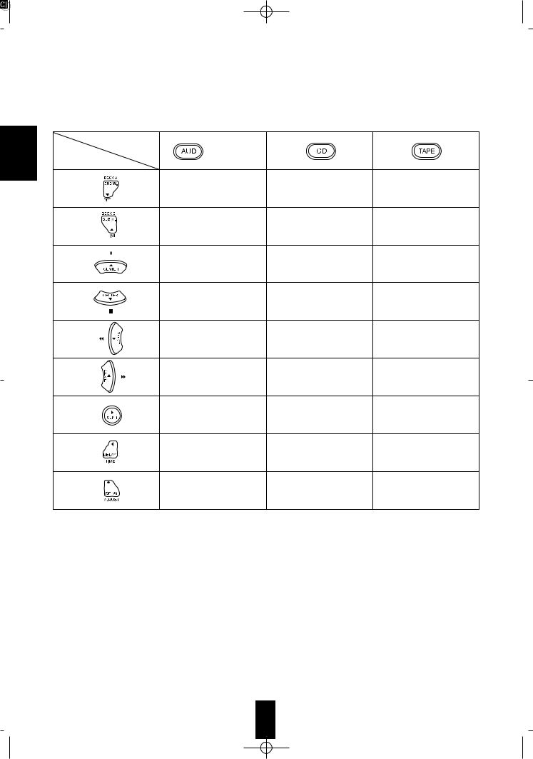
 FUNCTION TABLE of the NUMBERED BUTTONS.
Component control |
|
|
selection buttons |
|
|
(for pre amp.) |
|
|
Button symbols |
|
|
|
REPEAT A B |
DECK SELECTOR A |
|
INTRO SCAN |
DECK SELECTOR B |
CHANNEL LEVEL UP |
PAUSE |
PAUSE |
CHANNEL LEVEL DOWN |
STOP |
STOP |
|
BACKWARD SKIP |
REWIND |
|
FORWARD SKIP |
FAST-FORWARD |
SURROUND MODE |
PLAY |
FORWARD PLAY |
DELAY TIME |
|
REVERSE PLAY |
DELAY ADJUST |
|
RECORD |


 pressing PLAY, etc. on CD player or tape deck, CD or TAPE 2 MONITOR is selected automatically without selecting the input source and then PLAY, etc. starts.
In this case, to listen to TAPE 1, switch off the TAPE 2 MONITOR and select the TAPE 1.
Notes:
 Some functions for CD player, tape deck or equalizer may not be available.
 For details about functions, refer to the operating instructions of each component.
|
the components |
1 |
“ENTERING A |
|
|
|
the components you want to |
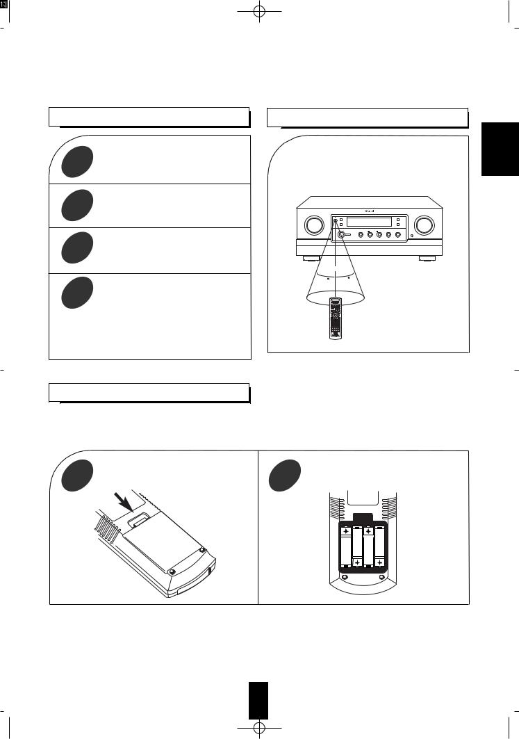
 Use the remote control within a range of about 7 meters (23 feet) and angles of up to 30 degrees aiming at the remote sensor.
2
3
button on the remote to the component
A/V TUNER PRE AMPLIFIER AVP-9080RDS |
7m
corresponding to the |
30 |
30 |
|
|
4 |
while aiming the |
|
|
|
the REMOTE SENSOR |
|
on the component. |
operating a Sherwood CD player or tape deck system remote control, aim the remote
at the REMOTE SENSOR on this unit.
When “L-BAT” flickers on the LCD, the old batteries should be replaced.
When changing the batteries, load the new batteries within 10 sec. to maintain existing programming.
If the batteries are removed for a longer period of time, the remote control might lose its memory and require re-programming.
1 |
Remove the cover. |
2 |
Load 4 AAA 1.5V batteries matching the |
|
polarity. |
ENGLISH
ENGLISH
ENTERING A SET-UP CODE
 Before operating audio and video components using the remote control supplied with this unit, the set-up code for each component must be entered.
 For system remote control operation, the set-up code for each Sherwood component such as CD player and tape deck is “001”respectively. Enter each set-up code for CD player and tape deck doing steps 3,4 and 5 as follows.
 The code for the AVP-9080R (or AVP-9080RDS) is Audio “002”.
component you want to control.
1 |
components, including this |
2 |
should be turned off and in the |
||
|
stanby mode before entering a set-up |
Example) The 3 digit set-up codes for the Sherwood |
|
code. |
|
|
“Audio” are 001,002, ...(Hint:The correct set- |
|
|
|
|
|
|
up code for this unit is “002”.) |
|
|
|
|
and the |
control |
3 |
|
4 |
|
|
Your component will be turned off when the correct |
||
|
|
set-up code is entered.(Example) In case of this unit, |
||
Then “SET” appears on the LCD of the remote |
this will be turned on,(refer to the above step1)) |
|
||
control for 20 seconds. |
Continue to enter the corresponding codes until your |
|||
|
|
component is turned off. |
|
|
|
|
If “SET” disappears, start from the step 3 again. |
|
|
|
Press the corresponding DEVICE button to |
|
using the |
|
5 |
store the set -up code. |
6 |
buttons on the remote |
|
|
OFF, CH |
and |
||
|
|
|
||
|
|
If any of the buttons do not perform as they should, start from |
||
|
|
step 1 again and enter the next set-up code. |
|
|
|
|
Notes:Some audio and video components have separate buttons |
||
|
|
for POWER ON/OFF. |
|
|
|
|
In this case, press the corresponding DEVICE(or POWER |
||
|
|
for this unit only) button to turn the component ON and |
||
|
|
press the POWER(or OFF for this unit only) button to turn |
||
|
|
the component OFF. |
|
|
|
|
If there is no correct set-up code or if the Manufacturer/Brand |
||
|
|
for your component is not listed in “Set-Up Code Tables” in |
||
|
|
the operating manual of this remote control, please use the |
||
|
|
“Auto Search Method” on page 10 in the operating manual of |
||
|
|
this remote control. |
|
|
Then PASS will flicker on the LCD. |
Although each set-up code is designed to work with many |
|||
|
|
different modes, certain codes may not work with some models. |
||
|
|
(Also, certain codes may only operate some of the functions |
||
|
|
available on a given model.) |
|
|
12
 Loading...