


ENGLISH
U N P A C K I N G A N D

Congratulations on Your Purchase!
Your new DVD receiver is designed to deliver maximum enjoyment and years of trouble free service.
Please take a few moments to read this manual thoroughly. It will explain the features and operation of your unit and help ensure a trouble free installation.
Please unpack your unit carefully. We recommend that you save the carton and packing material. They will be helpful if you ever need to move your unit and may be required if you ever need to return it for service. Your unit is designed to be placed in a horizontal position and it is important to allow at least two inches of space behind your unit for adequate ventilation and cabling convenience.
To avoid damage, never place the unit near radiators, in front of heating vents, in direct sunlight, in excessively humid, dusty locations or near sources of strong magnetic fields. Connect your complementary components as illustrated in the following section.
CAUTION
RISK OF ELECTRIC SHOCK
DO NOT OPEN
CAUTION : TO REDUCE THE RISK OF
ELECTRIC SHOCK, DO NOT
REMOVE COVER (OR BACK).
NO USER-SERVICEABLE PARTS
INSIDE. REFER SERVICING TO
QUALIFIED SERVICE PERSONNEL.
This symbol is intended to alert the user to the presence of uninsulated "dangerous voltage" within the product's enclosure that may be of sufficient magnitude to constitute a risk of electric shock to persons.
This symbol is intended to alert the user to the presence of important operating and maintenance
(servicing) instructions in the literature accompanying the appliance.
WARNING
To reduce the risk of fire or electric shock, do not expose this appliance to rain or moisture.
Caution : Do not block ventilation openings or stack other equipment on the top.
CLASS 1
LASER PRODUCT
CAUTION
Invisible laser radiation when the unit is open. Do not stare into beam.
CAUTION : USE OF ANY CONTROLS, ADJUSTMENTS, OR PROCEDURES OTHER THAN THOSE SPECIFIED HEREIN MAY RESULT IN HAZARDOUS RADIATION EXPOSURE.
FOR U.S.A
 Note to CATV System Installer: This reminder is provided to call the CATV system installer's attention to Article 820-40 of the NEC that provides guidelines for proper grounding and, in particular, specifies that the cable ground shall be connected to the grounding system of the building, as close to the point of cable entry as practical.
 FCC INFORMATION
This equipment has been tested and found to comply with the limits for a Class B digital device, pursuant to Part 15 of the FCC Rules. These limits are designed to provide reasonable protection against harmful interference in a residential installation. This equipment generates, uses and can radiate radio frequency energy and, if not installed and used in accordance with the instructions, may cause harmful interference to radio communications. However, there is no guarantee that interference will not occur in a particular installation. If this equipment does cause harmful interference to radio or television reception, which can be determined by turning the equipment off and on, the user is encouraged to try to correct the interference by one or more of the following measures:
•Reorient or relocate the receiving antenna.
•Increase the separation between the equipment and receiver.
•Connect the equipment into an outlet on a circuit different from that to which the receiver is connected.
•Consult the dealer or an experienced radio/TV technician for help.
CAUTION: Any changes or modifications in construction of this
device which are not expressly approved by the party responsible for compliance could void the user's authority to operate the equipment.
Caution regarding placement(Except for U.S.A and Canada)
To maintain proper ventilation, be sure to leave a space around the unit (from the largest outer dimensions including projections) equal to, or greater than, shown below.
Left and right panels: 5 cm
Rear panel: 10 cm
Top panel: 20 cm
PRECAUTIONS
 Moisture condensation
Moisture may form on the lens in the following conditions.
•Immediately after a heater has been turned on.
•In a steamy or very humid room.
•When this unit is moved from a cold place to a warm one.
If moisture forms inside this unit, it may not operate properly.
In this case, turn on the power and wait about one hour for the moisture to evaporate.
 If there is noise interference on the TV while a broadcast is being received.
Depending on the reception condition of the TV, interference may appear on the TV screen while you are watching a TV broadcast and this unit is left on. This is not a malfunction of this unit or the TV. To watch a TV broadcast, turn off this unit.
 Do not transport this unit with discs left in it.
2

READ THIS BEFORE OPERATING 

FOR U.S.A AND CANADA............................... |
120 V |
FOR YOUR SAFETY
Units shipped to the U.S.A and Canada are designed for operation on 120 V AC only.
Safety precaution with use of a polarized AC plug. However, some products may be supplied with a nonpolarized plug.
CAUTION : To prevent electric shock, match wide blade of plug to wide slot, fully insert.
ATTENTION : Pour eviter les choc electriques, introduire la lame la plug large de la borne correspondante de la prise et poussre jusqu'au fond.
FOR CHINA, EUROPE AND AUSTRALIA
..................................................... 220 V/230 V/240 V
FOR YOUR SAFETY
Units shipped to China are designed for operation on 220 V AC only.
Units shipped to Australia are designed for operation on 240 V AC only.
To ensure safe operation, the three-pin plug supplied must be inserted only into a standard three-pin power point which is effectively earthed through the normal household wiring. Extension cords used with the equipment must be three-core and be correctly wired to provide connection to earth.
Improper extension cords are a major cause of fatalities. The fact that the equipment operates satisfactorily does not imply that the power point is earthed and that the installation is completely safe. For your safety, if in any doubt about the effective earthing of the power point, consult a qualified electrician.
PAN-EUROPEAN UNIFIED VOLTAGE
All units are suitable for use on supplies 230-240 V AC.
ENGLISH
3

ENGLISH
CONTENTS |
|
Introduction |
|
UNPACKING AND INSTALLATION ........................................................................................................................................ |
2 |
READ THIS BEFORE OPERATING YOUR UNIT .................................................................................................................... |
3 |
System Connections ............................................................................................................................................................ |
5 |
Front Panel Controls ............................................................................................................................................................ |
9 |
Universal Remote Controls .............................................................................................................................................. |
10 |
ENTERING A SETUP CODE ................................................................................................................................................ |
11 |
OPERATING COMPONENTS WITH REMOTE CONTROL ................................................................................................. |
12 |
REMOTE CONTROL OPERATION RANGE ........................................................................................................................ |
12 |
LOADING BATTERIES ......................................................................................................................................................... |
12 |
Basic Operations |
|
LISTENING TO A PROGRAM SOURCE .............................................................................................................................. |
13 |
SURROUND SOUND ........................................................................................................................................................... |
16 |
ENJOYING SURROUND SOUND ........................................................................................................................................ |
20 |
Operation of DVD player |
|
PRELIMINARY KNOWLEDGE ABOUT DISCS .................................................................................................................... |
23 |
SYMBOL ABOUT INVALID OPERATION ............................................................................................................................ |
24 |
CARE AND HANDLING OF DISCS ...................................................................................................................................... |
24 |
DEFINITION OF TERMS ...................................................................................................................................................... |
25 |
BASIC PLAYBACK ................................................................................................................................................................ |
26 |
DISPLAYING DISC INFORMATION DURING PLAYBACK .................................................................................................. |
31 |
PLAYING THE DESIRED SECTION OF DISC (TITLE/CHAPTER/TIME SEARCH : DVD Video/CD only) ......................... |
32 |
PLAYING A SPECIFIC ITEM [DVD Video only] .................................................................................................................... |
33 |
REPEAT PLAYBACK ............................................................................................................................................................. |
34 |
PLAYING TRACKS IN DESIRED ORDER [CD only] ............................................................................................................ |
35 |
PLAYING TRACKS IN RANDOM ORDER [CD only] ............................................................................................................ |
36 |
CHANGING THE AUDIO LANGUAGE [DVD Video only] ...................................................................................................... |
37 |
CHANGING THE SUBTITLE LANGUAGE [DVD Video only] ................................................................................................ |
37 |
CHANGING THE CAMERA ANGLE [DVD Video only] ......................................................................................................... |
38 |
PLAYING A SCENE CLOSE-UP [DVD Video only] ............................................................................................................... |
38 |
CHANGING THE VIDEO SIGNAL FORMAT.......................................................................................................................... |
39 |
CHANGING THE COMPONENT VIDEO OUTPUT SIGNAL ................................................................................................. |
39 |
INITIAL SETTINGS ................................................................................................................................................................ |
40 |
Operation of Tuner |
|
LISTENING TO RADIO BROADCASTS ................................................................................................................................ |
52 |
LISTENING TO RDS BROADCASTS(FM only: VR-758R RDS TUNER only) ...................................................................... |
54 |
Operation of Other Functions |
|
RECORDING ......................................................................................................................................................................... |
56 |
DIGITAL AUDIO RECORDING WITH MD RECORDER ....................................................................................................... |
57 |
OTHER FUNCTIONS ............................................................................................................................................................ |
58 |
Troubleshooting Guide ..................................................................................................................................................... |
59 |
Specifications ...................................................................................................................................................................... |
61 |
DVD Language Code List ................................................................................................................................................. |
63 |
Setup Code Table ............................................................................................................................................................... |
64 |
4
• Please be certain that this unit is unplugged from the AC outlet before making any connections. |
|
|
• Since different components often have different terminal names, carefully read the operating instructions of the component |
|
|
connected. |
ENGLISH |
|
• Be sure to observe the color coding when connecting audio and video cords. |
||
|
||
• Make connections firmly and correctly. If not, poor connections can cause loss of sound, noise or damage to the unit. |
|
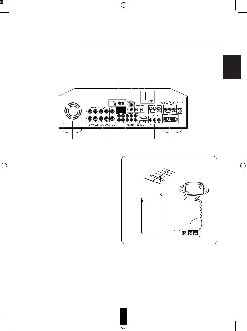
1 5 3 6
CAUTION: TO PREVENT ELECTRIC SHOCK, DO NOT
REMOVE COVER. NO USER-SERVICEABLE PARTS INSIDE.
REFER-SERVICING TO QUALIFIED SERVICE PERSONNEL.
7 |
4 |
2 |
2 |
8 |
1. Connecting antennas
•Change the position of the FM indoor antenna until you get the best possible reception of your favorite FM stations.
•A 75Ω outdoor FM antenna may be used to further improve the reception.
Disconnect the indoor antenna before connecting the outdoor one.
•Place the AM loop antenna as far as possible from this unit, TV set, speaker cords and the AC input cord and set it to a direction for the best reception.
•If the reception is poor with the AM loop antenna, an AM outdoor antenna can be used in place of the AM loop antenna.
FM
(OUTDOOR ANTENNA)
FM
(INDOOR ANTENNA)
AM loop antenna
5

ENGLISH
2. Connecting audio/video components
COMPOSITE VIDEO IN
COMPOSITE VIDEO OUT
S-VIDEO IN
S-VIDEO OUT
Video deck
Green |
Blue |
Red |
|
AUDIO PLAY(OUT) |
|
|
AUDIO REC(IN) |
|
Additional TV or |
AUDIO OUT |
|
audio component |
|
|
Tape deck or |
PLAY (OUT) |
|
REC (IN) |
||
MD recorder |
||
|
Monitor TV
COMPOSITE VIDEO IN
S-VIDEO IN
COMPONENT VIDEO IN
•The AUX/TV jacks may be connected to an additional TV or audio component such as a CD player, tape deck, etc..
•Only during playback of DVD Videos on this unit, the MONITOR COMPONENT VIDEO OUTs of this unit can be capable of outputting either conventional interlacing video signal or progressively scanned video signal (that can reproduce high-density pictures with less flicker).
•According to the types of video signals, the excellence in picture quality is as follows : “Progressive COMPONENT” > “Interlaced COMPONENT” > “S-VIDEO” > “COMPOSITE”
•When making COMPONENT VIDEO connections, connect “Y/PY” to “Y”(or PY), “Cb/Pb” to “Cb”(or “B-Y, “Pb”) and “Cr/Pr” to “Cr”(or “R-Y”, “Pr”).
•Depending on the type of the COMPONENT VIDEO INs of Monitor TV, be sure to set the COMPONENT VIDEO OUTPUT SIGNAL to the corresponding setting.
(Refer to “CHANGING THE COMPONENT VIDEO OUTPUT SIGNAL” on page 39.)
•A signal input into S-VIDEO IN jack will be output in the MONITOR S-VIDEO OUT jack only.
•In case of COMPOSITE VIDEO signal, a signal input into VIDEO 1 COMPOSITE VIDEO IN jack will be output in the MONITOR COMPOSITE VIDEO OUT jack only and a signal input into VIDEO 2 COMPOSITE VIDEO IN jack will be output in the VIDEO 1 and MONITOR COMPOSITE VIDEO OUT jacks.
Notes :
•When the COMPONENT VIDEO OUTPUT SIGNAL is set to PROGRESSIVE TV, the S-VIDEO and COMPOSITE VIDEO OUTs of this unit cannot output the video signals, meaning the picture will not be shown.
•When the progressive video signals are input into the non-progressive COMPONENT VIDEO INs of monitor TV, the picture may not be shown normally.
Therefore, when the progressive COMPONENT VIDEO INs of monitor TV are not connected to, you should set the COMPONENT VIDEO OUTPUT SIGNAL to INTERLACE TV.
•Do not connect the unit to the TV through a VCR. Otherwise the picture may be disturbed due to the copy protection function.
6
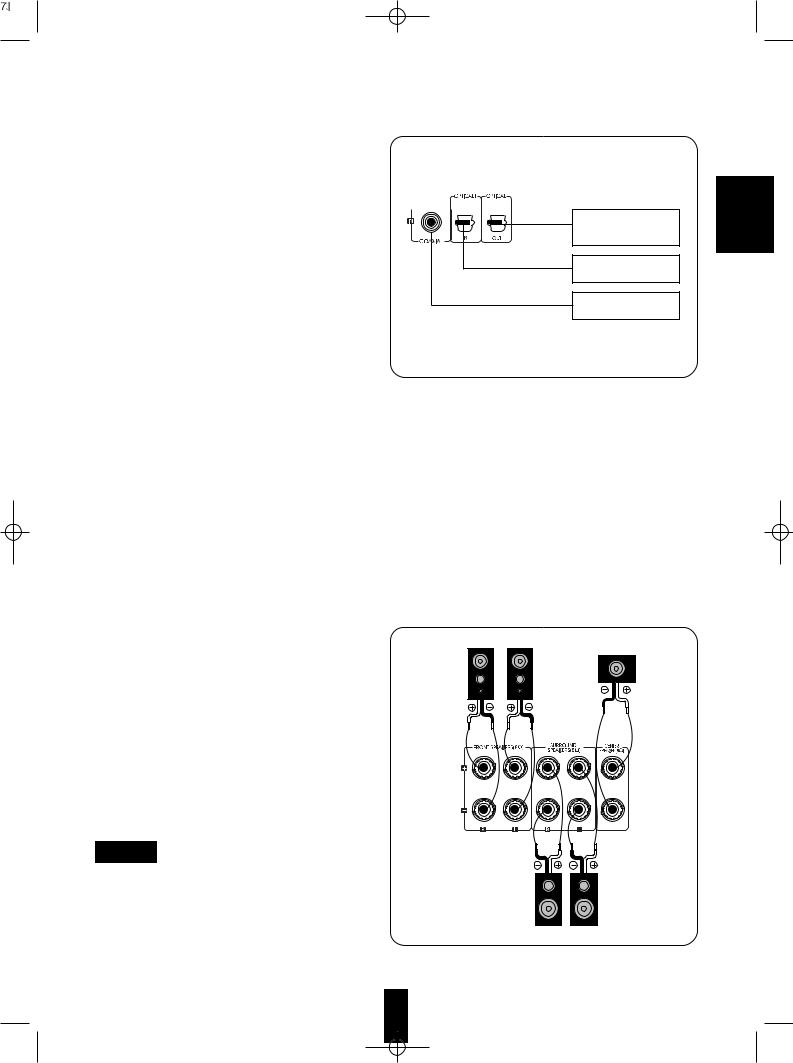
3. Connecting DIGITAL INs and
OUT
•The OPTICAL and COAXIAL DIGITAL OUTs of the components that are connected to AUX/TV, TAPE/MD, VIDEO 1 and VIDEO 2 of this unit can be connected to these DIGITAL INs.
•A digital input should be connected to the components such as LD player, CD player or DVD player, etc. capable of outputting DTS, Dolby Digital or PCM format digital signals, etc.
•If the MD recorder or CD recorder with OPTICAL IN jack is connected to the OPTICAL OUT jack of this unit, you can record the high quality sound of CDs, etc. without degradation. For details, refer to the operating instructions of the connected component.
•You can connect the OPTICAL OUT jack to the OPTICAL IN jack of an additional MPEG decoder, etc.
Notes :
•The OPTICAL DIGITAL OUT outputs the digital signal as it is being input into the OPTICAL or COAXIAL DIGITAL IN jack of this unit or it is being reproduced on the DVD player of this unit.
•When making the COAXIAL DIGITAL connection, be sure to use a 75Ω COAXIAL cord , not a conventional AUDIO cord.
•All of the commercially-available optical fiber cords cannot be used for audio equipments. If there is an optical fiber cord which cannot be connected to your audio equipments, consult your dealer or nearest service organization.
4. Connecting speakers
•Be sure to connect speakers firmly and correctly according to the channel (left and right) and the polarity (+ and -). If the connections are faulty, no sound will be heard from the speakers, and if the polarity of the speaker connections is incorrect, the sound will be unnatural and lack bass.
•For installing the speakers, refer to “Speaker placement” on page 17.
•After installing the speakers, first adjust the speaker settings according to your environment and speaker layout.(For details, refer to “Adjusting the speaker settings” on page 18.)
Caution
•Be sure to use the speakers with the impedance of 8 ohms or above.
•Do not let the bare speaker wires touch each other or any metal part of this unit.
This could damage this unit and / or the speakers.
Component(such as MD recorder, CD recorder, etc.) with OPTICAL DIGITAL IN
Component with
OPTICAL DIGITAL OUT
Component with
COAXIAL DIGITAL OUT
Front right |
Front left |
|
Center |
Surround right |
Surround left |
ENGLISH
7
ENGLISH
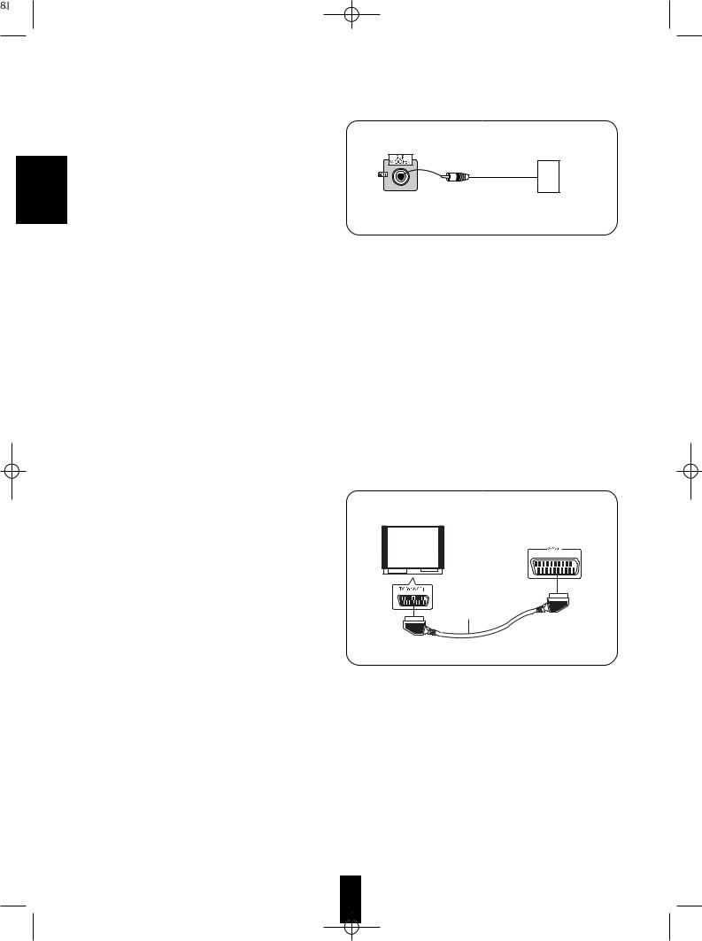
5. Connecting subwoofer
•To emphasize the deep bass sounds, connect a powered subwoofer.
6. AC INPUT CORD
• Plug this cord into a wall AC outlet.
7. COOLING FAN
•Cooling fan operates to prevent the temperature inside this unit from rising. The fan is sensitive to temperature and volume level. To allow for proper ventilation, maintain a certain space behind this unit.
Note :
•While the fan is operating, the faint fan noise is generated.
8.Connecting to TV with 21-pin SCART connector
•For some countries like Europe, this DVD player incorporates the A/V SCART connector.
•You can connect the unit to TV easily using the SCART connections without other cumbersome audio and video connections.
•During operation of the DVD player, this connector can deliver either the COMPOSITE(regular) VIDEO or the S-VIDEO(Y and C) signals as well as the audio L and R signals for easy connection.
•To obtain the highest picture quality, you can make the COMPONENT VIDEO connections between the unit and TV.
•Depending on the video signal(s) to be used, adjust SCART VIDEO settings to your preference and set your TV to the corresponding one to match the selected settings of the DVD player.(Refer to “When selecting the SCART VIDEO” on page 45 and the operating instructions of the TV connected.)
Note :
•In this connection, do not connect the unit to the TV through a VCR. Otherwise the image may be disturbed due to the copy protection function.
Powered subwoofer
Monitor TV
21-pin SCART cable(not supplied)
8

3 |
12 |
2 |
11 |
4 |
5 |
6 |
7 |
8 |
923 |
|
10 |
DVD RECEIVER VR-758R |
|
|
|
|
|
|
|
|
|
MASTER VOLUME |
ENGLISH |
|
|
|
|
|
|
RDS |
DISPLAY |
FM/AM MODE |
T/P MODE |
|
|
POWER |
|
|
|
|
|
|
|
|
|
|
|
1 |
PROGRESSIVE |
|
|
|
|
|
|
|
|
|
|
SCAN |
STANDBY |
|
|
|
|
|
|
|
|
||
ON/OFF |
|
|
|
|
|
|
|
|
|
|
|
|
|
|
|
|
|
|
|
VIDEO 2 INPUT |
PHONES |
DIGITAL |
INPUT |
DSP |
TONE |
CH. |
|
|
|
13 |
SPEAKER INPUTS |
SELECTOR |
MODE |
MODE |
SELECTOR |
ADJUST |
MEMO/ENTER |
|
ON/OFF MODE |
|
|
|
|
|
|
L-AUDIO-R OPTICAL 2 |
|
|
|
|
|
|
|
|
VIDEO |
|
|
14 15 16 17 |
18 19 20 |
21 |
22 |
24 |
|||
1.POWER SWITCH
2.STANDBY INDICATOR
3.DISC TRAY
4.OPEN / CLOSE( ) BUTTON
5.PLAY( ) BUTTON
6.STOP( )/ [RDS] BUTTON
7.STEP/PAUSE(
 ) / [DISPLAY] BUTTON
8.BACKWARD SKIP( 
 ) / [FM / AM MODE] BUTTON
9.FORWARD SKIP(
 ) / [T/P MODE] BUTTON
10.MASTER VOLUME CONTROL KNOB
11.REMOTE SENSOR
12.PROGRESSIVE SCAN INDICATOR
13.HEADPHONES JACK
14.SPEAKER ON/OFF BUTTON
15.SPEAKER MODE BUTTON
16.DIGITAL INPUT BUTTON
17.INPUT SELECTOR BUTTON
18.DSP MODE BUTTON
19.TONE MODE BUTTON
20.CHANNEL SELECTOR BUTTON
21.ADJUST UP / DOWN ( /
/ ) BUTTONS
22.MEMORY / ENTER BUTTON
 The functions in [ ] are available for tuner and RDS and DISPLAY of these are available for VR-758R RDS tuner only.
23. FLUORESCENT DISPLAY
24. VIDEO 2 INPUT JACKS
VIDEO 2 INPUT
VIDEO L-AUDIO-R OPTICAL 2
|
|
OPTICAL DIGITAL OUT |
COMPOSITE VIDEO OUT |
Additional video |
AUDIO OUT |
|
component |
•The VIDEO 2 INPUT jacks may be also connected to an additional video component such as a camcorder, a video deck or a video game player, etc.
•The OPTICAL DIGITAL OUTs of the components that are connected to AUX/TV, TAPE/MD, VIDEO 1 and VIDEO 2 of this unit can be connected to this OPTICAL 2 IN.
•This OPTICAL 2 IN should be connected to the component capable of outputting DTS, Dolby Digital or PCM format digital signals, etc.
•A signal input into VIDEO 2 COMPOSITE VIDEO IN jack will be output in the VIDEO 1 and MONITOR COMPOSITE
VIDEO OUT jacks.
•For details, refer to “Connecting audio / video components” on page 6 and “Connecting DIGITAL INs and OUT” on page 7.
 When not using the VIDEO 2 INPUT jacks
• Cover these jacks with the supplied cap.
REPEAT INDICATORS |
SURROUND MODE INDICATORS |
STEREO INDICATOR |
RDS INDICATORS |
ANGLE INDICATOR |
MEMORY INDICATOR |
DSP SURROUND INDICATOR |
PRESET CHANNEL |
PROGRAM INDICATOR |
INDICATOR |
TUNED INDICATOR |
CHANNEL |
|
INDICATORS |
MULTI-INFORMATION DISPLAY |
SPEAKER INDICATOR |
PAUSE INDICATOR |
|
PLAY INDICATOR |
|
9

ENGLISH
This universal remote control can operate not only this unit but also most popular brands of video components such as TVs, VCRs, cable boxes, satellite receivers, etc.
•To operate 4 components other than this unit, you should enter the setup code for each component. (For details, refer to “ENTERING A SETUP CODE” on page 11.)
•The numbered buttons on the remote control have different functions in other device modes.
For details, refer to “FUNCTION TABLE of the NUMBERED BUTTONS” on the next page.
POWER BUTTON 1
ADJUST(/CH LEVEL) UP/DOWN ( / ) BUTTONS
PL II MUSIC PARAMETER
BUTTON
DYNAMIC RANGE BUTTON
CLEAR BUTTON
REPEAT BUTTON 2
ANGLE BUTTON
PROGRAM BUTTON
TIME SEARCH BUTTON
NTSC/PAL BUTTON
SUBTITLE BUTTON
TITLE BUTTON
AUDIO BUTTON
SETUP BUTTON
DISPLAY BUTTON
BACKWARD/FORWARD( /
/
 ) SKIP,
PRESET DOWN/UP(-/+) BUTTONS
BACKWARD/FORWARD(  /
/ ) SEARCH, 7 TUNING DOWN/UP(-/+) BUTTONS
NUMERIC(0~9, +10) BUTTONS 8
POWER ON |
|
|
|
AUDIO |
|
|
|
|
|
DVD |
|
TV |
VCR |
|
CBL |
SAT |
|
ADJUST/CH LEVEL |
|
VOLUME |
|||
PARAMETER D. RANGE |
|
CH SEL. |
MUTE |
||
|
|
|
|
||
PL |
|
|
|
|
|
CLEAR |
REPEAT |
|
A< >B |
DSP MODE |
|
|
|
|
|
||
ANGLE |
PROGRAM RANDOM |
STEREO |
|||
|
|
|
|
||
T.SEARCH |
NTSC/PAL |
PBC |
PROGRESSIVE |
||
SCAN |
|||||
|
|
|
|
||
|
SUBTITLE |
|
AUDIO |
|
|
TITLE |
|
|
|
ZOOM |
|
SETUP |
|
MENU |
|||
|
ENTER |
|
|||
DISPLAY |
|
RETURN |
|||
PRESET |
|
|
|
||
TUNING |
|
STEP/ |
INPUT |
||
|
PAUSE |
||||
|
|
|
|
SEL. |
|
|
DIMMER |
SLEEP |
T.TONE |
||
+10 |
|
|
|
|
|
1 |
2 |
3 |
4 |
5 |
|
LED
DEVICE BUTTONS
To operate the desired component with this remote control, first select the corresponding DEVICE button.
4 VOLUME UP/DOWN( / ) BUTTONS
5 MUTE BUTTON
6 CHANNEL SELECTOR BUTTON DSP MODE BUTTON
3REPEAT A< >B BUTTON STEREO BUTTON
PROGRESSIVE SCAN BUTTON RANDOM PLAY BUTTON
ZOOM BUTTON
MENU BUTTON
CURSOR CONTROL( ,
, ,
, ,
,  ), ENTER BUTTONS
RETURN BUTTON
10 STOP(  ) BUTTON
9 PLAY( ) BUTTON
INPUT SELECTOR BUTTON
11STEP/PAUSE( 
 ) BUTTON TEST TONE BUTTON
SLEEP BUTTON DIMMER BUTTON
6 |
7 |
8 |
9 |
0 |
REMOTE CONTROL RM-108
Note :
• On the remote control, the PBC button is not available for this unit.
10

 FUNCTION TABLE of the NUMBERED BUTTONS
Device to be |
|
|
|
|
controlled |
TV (for TV) |
VCR (for VCR) |
CBL (for cable box) |
SAT (for satellite receiver) |
Button symbol
POWER ON
1
REPEAT
2
A<>B
3
VOLUME
4
MUTE
5
CH SEL.
6
TUNING
7
8 0  9
9  +10
+10
9
10
11 |
STEP/ |
PAUSE |
|
|
Notes:
•Some functions for each component may not be available or may work differently.
•Depending on other kinds of components that are available for each DEVICE button, some functions may not be available or may work differently, too.
•For details about functions, refer to the operating instructions of each component.
ENTERING A SETUP CODE
•This remote control can control up to 4 different components.
•Before operating video components other than this unit with using this remote control, the setup code for each component should be entered.
|
|
|
|
the type and |
|
1 |
|
2 |
|
referring to |
|
|
|
|
|||
|
both the ENTER |
|
|
remote |
|
3 |
button you want for |
4 |
|
the |
|
|
|
|
|||
TV |
: For TV |
|
|
|
|
VCR |
: For VCR |
|
|
|
|
CBL : For cable box |
0 |
0 |
1 |
||
|
|
|
|||
ENTER |
: For satellite receiver |
|
|
|
|
SAT |
|
|
|
||
|
|
• If entering is performed successfully, the LED will flicker |
|||
|
|
twice. |
|
|
|
|
|
• To be sure that the setup code is correct, press the |
|||
|
|
POWER button. If your component is turned off, the setup |
|||
• The LED will flicker once. |
|
code is correct. |
|
|
|
|
• When your component is not turned off, repeat the above |
||||
|
|
||||
Note: |
|
steps 2 to 4, trying each code for your component until |
|||
|
you find one that works. |
|
|
||
• The AUDIO/DVD button is unavailable for the |
|
|
|||
Notes: |
|
|
|||
components other than this unit. |
|
|
|||
• If the LED did not flicker twice, then repeat the above |
|||||
|
|
||||
|
|
steps 3 to 4 and try entering the same code again. |
|||
|
|
• Manufacturers may use different setup codes for the |
|||
|
steps 1 to 4 for each of |
same product category. For that reason, it is important |
|||
5 |
|
that you check to see if the code you have entered |
|||
|
operates as many controls as possible. If only a few |
||||
|
functions operate, check to see if another code will work |
||||
|
|
with more buttons. |
|
|
|
ENGLISH
11
ENGLISH
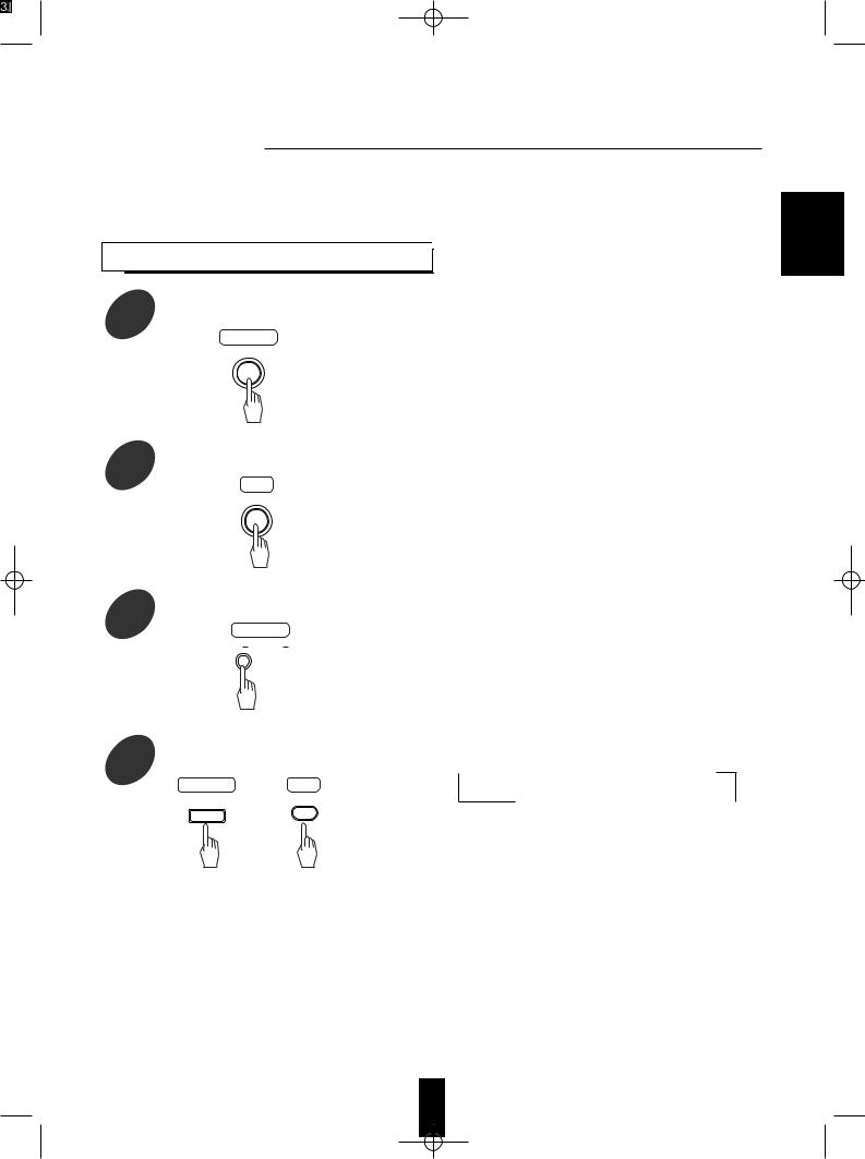
Enter the setup code for each component 1 other than this unit you wish to control.
For details, refer to “ENTERING A SETUP CODE” on page 11.
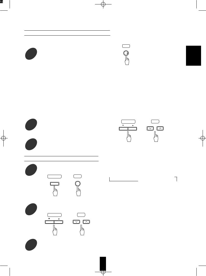
Turn on the component you want to operate.
Press the DEVICE button on the remote 3 control corresponding to the component
you wish to operate.
Example) When selecting “AUDIO/DVD” to operate this unit.
AUDIO
DVD
DVD RECEIVER VR-758R |
7m
30 |
30 |
Aim the remote control at the REMOTE 4 SENSOR of the component you wish to
control and press the button corresponding to the operation you want.
LOADING BATTERIES
•When the remote control does not operate, the old batteries should be replaced. In this case, load new batteries within several minutes after removing old batteries.
•If the batteries are removed or have been exhausted for a longer period of time, memorized contents will be cleared. Should this happen, you should memorize them again.
Remove the cover.
1
Load two batteries matching the polarity.
2 1.5V (“AAA” size)
•Remove the batteries when they are not used for a long time.
•Do not use the rechargeable batteries(Ni-Cd type).
•Be sure to use alkaline batteries.
12
 Before operation
•Before operating this unit with the supplied remote control, refer to “Universal Remote Controls” on page 10 for details about operation.
LISTENING TO A PROGRAM

Before operation, enter the standby mode.
Main unit
POWER
•The STANDBY indicator lights up.
This means that the unit is not disconnected from the AC mains and a small amount of current is retained to support the operation readiness.
•To switch the power off, push the POWER switch again. Then the power is cut off and the STANDBY indicator goes off.
In the standby mode, turn the power on.
RC
POWER ON
Switch the speakers on.
Main unit
SPEAKER
Select the desired input source.
4 Main unit RC
INPUT |
INPUT |
|
SELECTOR |
||
|
||
|
SEL. |
or
•Each time the POWER button on the remote control is pressed, the unit is turned on to enter the operating mode or off to enter the standby mode.
•In the standby mode, if the OPEN/CLOSE button is pressed or an input source is selected, the unit can be also turned on.
•The SPEAKER indicator lights up on the display and the sound can be heard from the speakers connected to the speaker terminals.
•When using the headphones for private listening, press the SPEAKER button again to switch the speakers off.
•Each time the INPUT SELECTOR button is pressed, the input source changes as follows :
 TUNER
TUNER  DVD
DVD  VIDEO 1
  VIDEO 2
(frequency display)
AUX / TV  TAPE / MD
ENGLISH
13

ENGLISH
Continued
When VIDEO 1, VIDEO 2, TAPE / MD or AUX / TV is selected
|
Select the digital or the analog input |
|
this button is pressed, the corresponding |
||||
5 |
desired. |
|
selected as follows : |
||||
Main unit |
|
OP (tical)2 CO (axial) AN (alog) |
|
|
|||
|
|
|
|||||
DIGITAL |
|
|
|
|
|||
|
INPUTS |
|
|
|
|
||
|
|
|
|
• To listen to DTS or Dolby Digital program sources in |
|||
|
|
|
|
the 2-CH downmix mode, the digital input must be |
|||
|
|
|
|
selected.(For details, refer to “2 CH downmix mode” |
|||
|
|
|
|
||||
|
|
|
|
on page 20.) |
|||
Notes :
•When DVD is selected as input source, the digital signals are reproduced automatically without selecting the signal input.
•When the selected digital input is not connected, no sound will be heard(Refer to “ENJOYING SURROUND SOUND” on page 20.)
•The sound from the component connected to the selected digital input can be heard regardless of the selected input source.
•When playing back the program sources with surround sound, refer to “ENJOYING SURROUND SOUND” on page 20.
Operate the selected component for play back.
Adjust the (overall) volume.
7
Main unit RC
VOLUME
MASTER VOLUME
or
Down
 Up
Up
Adjusting the tone (bass and treble)
Select the tone mode as desired
8
Main unit
TONE
MODE
•Each time this button is pressed, the corresponding tone mode is selected and shown for several seconds as follows :
 BASS
BASS  TREBLE
  TONE CONTROL
or TONE DEFEAT
•If the tone display disappears, press the TONE MODE button again.
•When the tone defeat mode is selected (“TONE DEFEAT”), bass and treble modes cannot be selected.
14

Continued
At the desired tone mode, adjust as 9 desired.
Main unit |
RC |
ADJUST |
ADJUST/CH LEVEL |
or
tone control or tone defeat mode, each ADJUST(/CH LEVEL) UP(
 ) or
) or

 ) button is pressed, the tone mode as follows:
DEFEAT : When listening to a program source without the tone effect.
CONTROL : When adjusting the tone for your taste.
To mute the sound.
RC
MUTE
To listen with the headphones.
Main unit
PHONES
 At the desired tone (bass or treble), each time the ADJUST(/CH LEVEL) UP(
 ) or DOWN(
 ) button is pressed, the tone level can be adjusted within the range of -10~ +10dB
•In general, we recommend the bass and treble to be adjusted to 0(flat) level.
•To complete tone adjustment, repeat the above steps 8 and 9.
 Notes :
•Extreme settings at high volume may damage your speakers.
•When the digital signals from DTS, Dolby Digital program sources, etc. are played back, the tone control cannot be adjusted and the tone defeat mode is automatically selected.
•The STANDBY indicator will flicker.
•To resume the previous sound level, press the button again.
•Ensure that the SPEAKER button is set to off.
•When listening to a DTS or Dolby Digital program source, if the headphones are plugged in and the SPEAKER button is set to off, it enters the 2-CH downmix mode automatically.(For details, refer to “2 CH downmix mode” on page 20.)
ENGLISH
15

ENGLISH
SURROUND SOUND
•This receiver incorporates a sophisticated Digital Signal Processor that allows you to create optimum sound quality and sound atmosphere in your personal Home Theater.
Surround modes
 DTS Digital Surround
DTS Digital Surround(also called simply DTS) is a multi-channel digital signal format which can handle higher data rates than Dolby Digital. Although both Dolby Digital and DTS are 5.1 channel formats, discs bearing the “  ” are generally thought to
provide better sound quality due to the lower audio compression required.
It also provides wide dynamic range and separation, resulting in magnificent sound.
“DTS” and “DTS Digital Surround” are registered trademarks of Digital Theater Systems, Inc
 Dolby Digital
Dolby Digital is the multichannel digital signal format developed by Dolby Laboratories. Discs bearing the “ ” includes the recording of up
to 5.1 channels of digital signals, which can reproduce much better sound quality, spatial expansion and dynamic range characteristics than the previous Dolby Surround effect.
•Some sources marked Dolby Digital may be recorded in Dolby Surround, a 2 channel system.
 Dolby Pro Logic II surround
This mode applies conventional 2- channel signals such as digital PCM or analog stereo signals as well as Dolby Surround signals from sources bearing the “ ” , etc. to surround processing to offer improvements over conventional Dolby Pro Logic circuits. Dolby Pro Logic II surround includes two modes as follows:
Dolby Pro Logic II MOVIE
When enjoying movies, this mode allows you to further enhance the cinematic quality by adding processing that emphasizes the sounds of the action special effects.
Dolby Pro Logic II MUSIC
When listening to music, this mode allows you to further enhance the sound quality by adding processing that emphasizes the musical effects.
Manufactured under license from Dolby Laboratories. “Dolby”, “Pro Logic”, and the double-D symbol are trademarks of Dolby Laboratories.
•The following modes apply conventional 2-channel signals such as digital PCM or analog stereo signals to high performance Digital Signal Processor to recreate sound fields artificially.
Select one of the four provided surround modes according to the program source you want to play.
 Theater
This mode provides the effect of being in a movie theater when watching a movie.
 Hall
Hall
This mode provides the ambience of a concert hall for classical music sources such as orchestral, chamber music or an instrumental solo.
 Stadium
This mode provides the expansive sound field to achieve the true stadium effect when watching baseball or soccer games.
 5 CH stereo
This mode provides a wider, deeper and more natural sound stage from 2-channel source material. This is done by feeding the left channel signal to both front and surround left speakers and the right channel signal to both front and surround right speakers.
Additionally, the center channel reproduces a mix of the right and left channels.
16
For your reference, the sound from each channel can be reproduced according to the surround modes as follows:
|
Modes |
Dolby Digital |
Dolby Pro Logic II |
Other Surround |
Stereo |
Channels |
DTS |
||||
|
|
|
|
|
Front L/R
Center
Surround L/R
Subwoofer
•Depending on the speaker settings and the number of the encoded channels, the sound from the corresponding channels cannot be reproduced.(For details, refer to “Adjusting the speaker settings” on next page)
(*) : Depending on the speaker settings, the sound from the subwoofer channel may be reproduced.
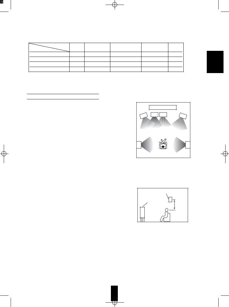
Speaker placement
Ideal speaker placement varies depending on the size of your room and the wall coverings, etc. The typical example of speaker placement and recommendations are as follows :
 Front left and right speakers and center speaker
 Place the front speakers with their front surfaces as flush with TV or monitor screen as possible.
 Place the center speaker between the front left and right speakers and no further from the listening position than the front speakers.
 Place each speaker so that sound is aimed at the location of the listener’s ears when at the main listening position.
 Surround left and right speakers
 Place the surround speakers approximately 1 meter (40 inches) above the ear level of a seated listener on the direct left and right of them or slightly behind.
 Subwoofer
 The subwoofer reproduces powerful deep bass sounds. Place a powered subwoofer anywhere in the front as desired.
 Notes :
 When using a conventional TV, to avoid interference with the TV picture, use only magnetically shielded front left and right and center speakers.
 To obtain the best surround effects, the speakers except the subwoofer should be full range speakers.
|
|
1 |
|
2 |
3 |
4 |
5 |
|
|
||
6 |
|
|
7 |
|
|
8 |
|
1. |
TV or screen |
6. |
Surround left speaker |
2. |
Front left speaker |
7. |
Surround right speaker |
3. |
Subwoofer |
8. |
Listening position |
4.Center speaker
5.Front right speaker
Surround speaker
Front speaker
60 to 90 cm
ENGLISH
17

ENGLISH
Adjusting the speaker settings
•After you have installed this unit and connected all the components, you should adjust the speaker settings for the optimum sound acoustics according to your environment and speaker layout.
•There are two kinds of speaker settings for speaker size and speaker distance.
 Speaker size settings
Select the corresponding settings depending on the sizes of the connected speakers and whether the speakers are connected or not.
•Depending on your speaker type, you can select one of these following settings.
Large : Select this when connecting speakers that can fully reproduce sounds below 120 Hz.
Small : Select this when connecting speakers that cannot fully reproduce sounds below 120 Hz.
When this is selected, sounds below 120 Hz are sent to the subwoofer or the front speakers depending on whether the subwoofer setting is
Yes or No.
None : Select this when no speakers are connected.
When this is selected, sounds are sent to the front speakers.
Yes / No : Select the desired depending on whether a subwoofer is connected or not.
•Depending on relationship between speakers, settings possible for speakers are as follows:
Front L/R |
Center |
Surround L/R |
Subwoofer |
||
|
|
Large |
|
|
|
|
|
|
|
|
|
|
Large |
Small |
|
|
|
|
|
|
|
|
|
|
|
None |
|
|
|
|
|
|
|
||
Large |
|
Large |
Yes |
||
|
|
|
|
||
|
Small |
Small |
or |
||
|
|
|
|
||
|
|
None |
No |
||
|
|
Large |
|
|
|
|
|
|
|
|
|
|
None |
Small |
|
|
|
|
|
|
|
|
|
|
|
None |
|
|
|
|
Small |
Small |
Yes |
|
|
|
|
||||
|
None |
||||
|
|
or |
|||
|
|
|
|||
Small |
None |
Small |
|||
No |
|||||
|
|
||||
|
None |
||||
|
|
|
|
||
|
|
|
|
|
|
 Speaker distance settings
When enjoying 5.1 channel surround playback with Dolby Digital and DTS sources, etc., it is ideal that the center and surround speakers should be the same distance from the main listening position as the front speakers.
By entering the distance between the listening position and each speaker, the delay times of center and surround speakers are automatically adjusted to create an ideal listening environment virtually (as if the center and surround speakers were at their ideal locations respectively as below.)
Ideal location of a center speaker
FL SW C |
FR |
|
Dc |
|
Df |
|
Ds |
SL |
SR |
All speakers should be located within a circle with a radius of Df
Ideal location of a surround speaker
Df : Distance between front speakers and listening position Dc : Distance between center speakers and listening position
Ds : Distance between surround speakers and listening position
18

Continued
Refer to the previous page and adjust the speaker settings.
Note: When the SPEAKER button is set to off, the speaker setting function cannot be available.
1
2
Select the desired speaker setting mode.
Main unit
SPEAKER
At the desired setting mode, select the desired setting.
Main unit |
RC |
ADJUST |
ADJUST/CH LEVEL |
or
• Each time this button is pressed, the speaker setting mode changes in succession and its current setting flickers for several seconds as follows :
FRONT L 3.3 M |
3.3 M |
CNTR L 3.3 M |
3.3 M |
SUBWOOFER-Y |
1.8 M |
SURR L 1.8 M |
|
•L: Large, S: Small, N: No or None, Y: Yes,
M:Meters, CNTR: Center, SURR: Surround
•When the speaker size is set to “N”, “--” is displayed instead of the distance and its distance setting mode cannot be selected.
•When the speaker setting mode disappears, press the SPEAKER MODE button repeatedly to select the desired mode.
on the speaker setting modes, each time these buttons are pressed, the setting changes as follows :
 When the speaker size setting mode is selected
• In case of front, center and surround speaker size setting mode
 (L
(L  )S(
)S( N)
N)  • At the front speaker size setting mode, “N” cannot be selected.
• When the front speaker size is set to “S”, the center and surround speaker sizes cannot be set to “L”.
• In case of subwoofer setting mode Y N
N
When the speaker distance setting mode is selected |
|
|||
|
0.3 0.6 ....... 8.7 9.0 |
|
|
• You can adjust the distance within the range of |
|
|
|
||
|
|
|
|
0.3~9meters in 0.3 meter intervals |
|
|
|
|
|
Repeat the above steps 1 and 2 until the speaker setting are all adjusted.
Memorize the speaker settings you adjust.
4 |
Main unit |
RC |
you adjust are stored in the |
MEMO/ENTER |
|
||
|
|
memory. |
|
|
|
ENTER |
or
ENGLISH
19

ENGLISH
ENJOYING SURROUND SOUND

1 |
Main unit |
RC |
|
DSP |
DSP MODE |
|
MODE |
|
or
•Depending on the signal format which is being reproduced, each time this button is pressed, the surround mode changes as follows :
*When the digital signals from the DTS sources are reproduced.
 DTS 5.1 CH(DTS)
  (2 CH DOWNMIX)
*When the digital signals from the Dolby Digital sources are reproduced
 DD 5.1 CH(Dolby Digital)
  (2 CH DOWNMIX)
*When the 2 channel digital signals from the Dolby Digital or Dolby Surround sources are reproduced.
 PL 2(Dolby Pro Logic II) MOVIE
  PL 2 (Dolby Pro Logic II) MUSIC
  (STEREO)
* When the digital signals recorded in 2 channel PCM or the 2 channel analog signals are reproduced.
 PL 2(Dolby Pro Logic II) MOVIE
  PL 2(Dolby Pro Logic II) MUSIC
  THEATER
  HALL
HALL  STADIUM
  5 CH STEREO
  (STEREO)
• ( ): When selecting the 2 CH downmix mode or the stereo mode on the remote control, press the STEREO button.
Note :
• Noise may be generated at the beginning of playback and while searching during DTS playback.
 When canceling the surround mode for normal stereo operation
• Depending on the signal format which is being
RC
reproduced, either the stereo mode or the 2 CH
STEREO
downmix mode is selected.
• You can select either the stereo mode or the 2 CH downmix mode with using the DSP MODE button on the main unit.
• To cancel either the stereo mode or the 2 CH downmix mode, select the desired surround mode with using the DSP MODE button.
 2 CH downmix mode
•This mode allows the multi-channel DTS or Dolby Digital signals to be mixed down into 2 front channels and to be reproduced through only two front speakers or through headphones.
•If the headphones are plugged and the SPEAKER button is set to off while the digital signals from the DTS or Dolby Digital sources are being reproduced, it will enter the 2-CH downmix mode automatically and if the headphones are unplugged and the SPEAKER button is set to on in the 2-CH downmix mode, it will return to the previous mode.
20
Adjusting the Dolby Pro Logic II Music parameters
•When selecting the Dolby Pro Logic II Music mode, you can adjust the various surround parameters for optimum sound effect.
mode, |
RC |
PARAMETER |
2 |
PL |
•Each time this button is pressed, the parameter changes and is displayed for several seconds as follows :
*Panorama mode (“PANORAMA”, initial setting : OFF)
This mode extends the front stereo image to include the surround speakers for an exciting “wraparound” effect with side wall imaging. Select “OFF” or “ON”.
* Center width control (“C-WIDTH”, initial setting : 3)
This adjusts the center image so it may be heard only from the center speaker, only from the left/right speakers as a phantom image, or from all three front speaker to varying degrees.
The control can be set in 8 steps from 0 to 7.
* Dimension control (“DIMENSION”, initial setting : 0)
This gradually adjusts the soundfield either towards the front or towards the rear. The control can be set in 7 steps from -4 to +2.
• If the parameter display disappears, press the PL II MUSIC PARAMETER button again.
desired parameter, adjust it as |
RC |
Main unit |
3 |
ADJUST |
ADJUST/CH LEVEL |
or
steps 2 and 3 to adjust
4
Adjust each channel level
5
Main unit |
RC |
CH. |
CH SEL. |
SELECTOR |
|
or
the level of the selected channel as
•Each time this button is pressed, the corresponding channel is selected and displayed for several seconds as follows :
 FRONT-L
  CENTER
  FRONT-R
  SURR-R SUBWOOFER
  SURR-L
•When it is in the stereo or 2 CH downmix mode or the speaker setting is “N”, center, surround or subwoofer channel will not be selected.
•When the SPEAKER button is set to off, only the front channels can be selected.
6 |
Main unit |
RC |
• If the channel display disappears, start from the |
|
ADJUST |
ADJUST/CH LEVEL |
above step 5 again.
or
adjust each channel level until the sound level of each
7
ENGLISH
21
ENGLISH
Adjusting each channel level with test tone
• The volume level of each channel can be adjusted easily with the test tone function.
8
9
RC
T.TONE
the level as desired each speaker is
Main unit |
RC |
ADJUST |
ADJUST/CH LEVEL |
or
•The test tone will be heard from the speaker of each channel for 2 seconds as follows :
 FRONT-L
  CENTER
  FRONT-R
  SURR R
SUBWoofer  SURR L
•When the speaker setting is “N”, the test tone of the corresponding channel is not available.
•When the SPEAKER button is set to off, the test tone function cannot work.
•You can select the desired channel and adjust its level with repeating the steps 5 and 6 in “Adjusting each channel level” procedure.
RC
T.TONE
Adjusting the LFE level
•You can adjust the LFE (Low Frequency Effect) levels included in Dolby Digital and DTS program sources.
•LFE channel is an additional channel exclusively reserved for additional deep bass sound effects of “5.1” channels, also called the “.1” channel.
CHANNEL SELECTOR button 2 seconds to enter the LFE
Main unit |
RC |
CH. |
CH SEL. |
SELECTOR |
|
or
the level of the selected LFE as
Main unit |
RC |
ADJUST |
ADJUST/CH LEVEL |
or
•Each time this button is pressed in the LFE level mode, the LFE level changes and is displayed for several seconds as follows :
 Dolby Digital LFE
  DTS LFE
•Each time these buttons are pressed, the LFE level can be adjusted within the range of either -10~0 dB for Dolby Digital program sources or -10~+10 dB for DTS program sources.
•In general, we recommend the LFE level to be adjusted to 0dB.(However, the recommended LFE level for some early DTS software is -10 dB.) If the recommended levels seem too high, lower the setting as necessary.
•If the LFE level display disappears, start from the step 11 again.
22
 Loading...