

Page 1

TAC I/A Series MicroNet BACnet
Wiring, Networking, and
Best Practices Guide
Page 2

Page 3

TAC I/A Series MicroNet BACnet
Wiring, Networking, and
Best Practices Guide
Printed in U.S.A. 06-14 F-27360-11
Page 4

Distributed, manufactured, and sold by Schneider Electric.
I/A Series trademarks are owned by Invensys Systems, Inc. and are
used on this product under master license from Invensys. Invensys does
not manufacture this product or provide any product warran ty or support.
For service, support, and warranty information, contact
Schneider Electric.
All brand names, trademarks and registered trademarks are the property of th eir respective owners. Information contained within this document is subj ect to change
without notice.
Schneider Electric
F-27360-11 June 2014 tl
© 2014 Schneider Electric. All rights reserved.
Page 5

Table of Contents
Preface
Purpose of this Manual . . . . . . . . . . . . . . . . . . . . . . . . . . . . . . . . . . . . ix
Applicable Documentation . . . . . . . . . . . . . . . . . . . . . . . . . . . . . . . . . x
Related Documentation . . . . . . . . . . . . . . . . . . . . . . . . . . . . . . . . . . . xi
Conventions Used in this Manual . . . . . . . . . . . . . . . . . . . . . . . . . . . .xii
Acrobat (PDF) Conventions . . . . . . . . . . . . . . . . . . . . . . . . . . . . . .xii
Abbreviations and Terms Used in this Manual . . . . . . . . . . . . . . .xii
Manual Summary . . . . . . . . . . . . . . . . . . . . . . . . . . . . . . . . . . . . . . . .xii
Chapter 1 I/A Series BACnet Hardware
MicroNet BACnet Controllers . . . . . . . . . . . . . . . . . . . . . . . . . . . . . . . . . 2
Common Controller Features . . . . . . . . . . . . . . . . . . . . . . . . . . . . . . . 2
BACnet Compliance . . . . . . . . . . . . . . . . . . . . . . . . . . . . . . . . . . . . . . 2
MNB-300 Unitary Controller . . . . . . . . . . . . . . . . . . . . . . . . . . . . . . . . 3
MNB-V1, MNB-V2 VAV Controllers . . . . . . . . . . . . . . . . . . . . . . . . . . 5
MNB-70 Zone Controllers . . . . . . . . . . . . . . . . . . . . . . . . . . . . . . . . . . 7
MNB-1000 Plant Controller . . . . . . . . . . . . . . . . . . . . . . . . . . . . . . . . 9
MNB-1000-15 Remote I/O Module . . . . . . . . . . . . . . . . . . . . . . . . . . 13
Input and Output Specifications . . . . . . . . . . . . . . . . . . . . . . . . . . . . 15
Universal Inputs . . . . . . . . . . . . . . . . . . . . . . . . . . . . . . . . . . . . . . 15
Universal Outputs . . . . . . . . . . . . . . . . . . . . . . . . . . . . . . . . . . . . 16
Digital Inputs . . . . . . . . . . . . . . . . . . . . . . . . . . . . . . . . . . . . . . . . 16
Digital Outputs, Triac . . . . . . . . . . . . . . . . . . . . . . . . . . . . . . . . . . 17
20 Vdc Output . . . . . . . . . . . . . . . . . . . . . . . . . . . . . . . . . . . . . . . 18
Inputs from MN-Sx MicroNet Sensor . . . . . . . . . . . . . . . . . . . . . . 19
Velocity Pressure Input . . . . . . . . . . . . . . . . . . . . . . . . . . . . . . . . 20
MicroNet Digital Wall Sensors . . . . . . . . . . . . . . . . . . . . . . . . . . . . . . . 21
Common Sensor Features . . . . . . . . . . . . . . . . . . . . . . . . . . . . . . . . 22
Keypad Icons . . . . . . . . . . . . . . . . . . . . . . . . . . . . . . . . . . . . . . . . . . 22
LCD Icons . . . . . . . . . . . . . . . . . . . . . . . . . . . . . . . . . . . . . . . . . . . . 23
Diagnostic Functions . . . . . . . . . . . . . . . . . . . . . . . . . . . . . . . . . . . . 23
Communications Wiring . . . . . . . . . . . . . . . . . . . . . . . . . . . . . . . . . . . . 25
Intermixing of Cables . . . . . . . . . . . . . . . . . . . . . . . . . . . . . . . . . . . . 25
F-27360-11 MicroNet BACnet Wiring, Networking, and Best Practices Guide iii
Page 6

Table of Contents
Chapter 2 Networking Practices
Sensor Link (S-Link) Wiring . . . . . . . . . . . . . . . . . . . . . . . . . . . . . 26
MicroNet MS/TP Network Wiring . . . . . . . . . . . . . . . . . . . . . . . . . 26
ADI and Remote I/O Network Wiring . . . . . . . . . . . . . . . . . . . . . . 27
I/O Wiring . . . . . . . . . . . . . . . . . . . . . . . . . . . . . . . . . . . . . . . . . . . 27
Power Supply Wiring . . . . . . . . . . . . . . . . . . . . . . . . . . . . . . . . . . 28
Sensor Link (S-Link) Wiring . . . . . . . . . . . . . . . . . . . . . . . . . . . . . . . 28
MicroNet MS/TP Network Wiring . . . . . . . . . . . . . . . . . . . . . . . . . . . 29
Cable Specifications . . . . . . . . . . . . . . . . . . . . . . . . . . . . . . . . . . . 29
Approved Cable Types . . . . . . . . . . . . . . . . . . . . . . . . . . . . . . . . . 30
ADI and Remote I/O Module Network Wiring . . . . . . . . . . . . . . . . . . 31
Wiring Specifications for ADI or Remote I/O . . . . . . . . . . . . . . . . 31
I/O Wiring . . . . . . . . . . . . . . . . . . . . . . . . . . . . . . . . . . . . . . . . . . . . . 32
Power Supply Wiring . . . . . . . . . . . . . . . . . . . . . . . . . . . . . . . . . . . . . . . 34
Introduction to BACnet . . . . . . . . . . . . . . . . . . . . . . . . . . . . . . . . . . . . . 39
Architecture Overview . . . . . . . . . . . . . . . . . . . . . . . . . . . . . . . . . . . . . . 40
Introduction . . . . . . . . . . . . . . . . . . . . . . . . . . . . . . . . . . . . . . . . . . . . 40
MS/TP Network Configuration . . . . . . . . . . . . . . . . . . . . . . . . . . . . . . . . 42
Physical Limits . . . . . . . . . . . . . . . . . . . . . . . . . . . . . . . . . . . . . . . . . 42
Number of Connected Devices . . . . . . . . . . . . . . . . . . . . . . . . . . 42
Logical Limits . . . . . . . . . . . . . . . . . . . . . . . . . . . . . . . . . . . . . . . . . . 42
Addressing Limit . . . . . . . . . . . . . . . . . . . . . . . . . . . . . . . . . . . . . . 42
Limits to Number of Polled Points . . . . . . . . . . . . . . . . . . . . . . . . 43
Limits to Resources . . . . . . . . . . . . . . . . . . . . . . . . . . . . . . . . . . . 43
Connection to an MS/TP Network . . . . . . . . . . . . . . . . . . . . . . . . . . 44
Remote I/O Network Configuration . . . . . . . . . . . . . . . . . . . . . . . . . . . . 44
Connections . . . . . . . . . . . . . . . . . . . . . . . . . . . . . . . . . . . . . . . . . . . 44
Physical Limits . . . . . . . . . . . . . . . . . . . . . . . . . . . . . . . . . . . . . . . . . 45
Number of Connected Devices . . . . . . . . . . . . . . . . . . . . . . . . . . 45
Logical Limits . . . . . . . . . . . . . . . . . . . . . . . . . . . . . . . . . . . . . . . . . . 45
Addressing Limit . . . . . . . . . . . . . . . . . . . . . . . . . . . . . . . . . . . . . . 45
Increased I/O Count . . . . . . . . . . . . . . . . . . . . . . . . . . . . . . . . . . . 46
MS/TP Network Considerations . . . . . . . . . . . . . . . . . . . . . . . . . . . . . . 46
Master and Slave Devices . . . . . . . . . . . . . . . . . . . . . . . . . . . . . . . . 46
Physical Addressing . . . . . . . . . . . . . . . . . . . . . . . . . . . . . . . . . . . . . 46
Required Configuration . . . . . . . . . . . . . . . . . . . . . . . . . . . . . . . . 46
Optimization . . . . . . . . . . . . . . . . . . . . . . . . . . . . . . . . . . . . . . . . . 47
MS/TP Address for BACnet Tools . . . . . . . . . . . . . . . . . . . . . . . . 47
Other Network Setup Considerations . . . . . . . . . . . . . . . . . . . . . . . . . . 48
Port Bridging . . . . . . . . . . . . . . . . . . . . . . . . . . . . . . . . . . . . . . . . . . . 49
Single Path to Device . . . . . . . . . . . . . . . . . . . . . . . . . . . . . . . . . . . . 50
Routers and Network Numbers . . . . . . . . . . . . . . . . . . . . . . . . . . 50
Network Setup Procedures . . . . . . . . . . . . . . . . . . . . . . . . . . . . . . . . . . 51
Overview . . . . . . . . . . . . . . . . . . . . . . . . . . . . . . . . . . . . . . . . . . . . . . 51
Physical Installation . . . . . . . . . . . . . . . . . . . . . . . . . . . . . . . . . . . . . 51
Set the DIP Switches on the Controllers . . . . . . . . . . . . . . . . . . . . . . 52
iv MicroNet BACnet Wiring, Networking, and Best Practices Guide F-27360-11
Page 7

MS/TP Network . . . . . . . . . . . . . . . . . . . . . . . . . . . . . . . . . . . . . . 52
Remote I/O Network . . . . . . . . . . . . . . . . . . . . . . . . . . . . . . . . . . 52
Power on the MNB-xxxx Devices . . . . . . . . . . . . . . . . . . . . . . . . . . . 52
Commission UNCs and ENCs . . . . . . . . . . . . . . . . . . . . . . . . . . . . . 52
Commission the Controllers . . . . . . . . . . . . . . . . . . . . . . . . . . . . . . . 52
Chapter 3 Checkout and Troubleshooting
Mechanical Hardware Checkout . . . . . . . . . . . . . . . . . . . . . . . . . . . . . . 53
Communications Hardware Checkout . . . . . . . . . . . . . . . . . . . . . . . . . 55
Service . . . . . . . . . . . . . . . . . . . . . . . . . . . . . . . . . . . . . . . . . . . . . . . 62
Field-replaceable Units . . . . . . . . . . . . . . . . . . . . . . . . . . . . . . . . . . . 62
BACnet Best Practices
I/A Series MicroNet BACnet System Architecture Overview . . . . . . . . 64
MS/TP Network Overview . . . . . . . . . . . . . . . . . . . . . . . . . . . . . . . . . . 67
Master-Slave Token Passing . . . . . . . . . . . . . . . . . . . . . . . . . . . . . . 67
Device Addressing . . . . . . . . . . . . . . . . . . . . . . . . . . . . . . . . . . . . . . 69
BACnet Rules that Must be Followed . . . . . . . . . . . . . . . . . . . . . . . . . . 69
General BACnet Rules . . . . . . . . . . . . . . . . . . . . . . . . . . . . . . . . . . . 69
No Duplicate Device Instances . . . . . . . . . . . . . . . . . . . . . . . . . . 69
No Duplicate Object Identifiers within a Device . . . . . . . . . . . . . . 69
No Duplicate Network Numbers . . . . . . . . . . . . . . . . . . . . . . . . . . 69
Devices on a Network Must Share a Single Network Number . . . 69
One Communication Path Only . . . . . . . . . . . . . . . . . . . . . . . . . . 69
MS/TP Network Rules . . . . . . . . . . . . . . . . . . . . . . . . . . . . . . . . . . . 70
No Duplicate Addresses . . . . . . . . . . . . . . . . . . . . . . . . . . . . . . . 70
Install Terminators . . . . . . . . . . . . . . . . . . . . . . . . . . . . . . . . . . . . 71
Set Bias Resistors . . . . . . . . . . . . . . . . . . . . . . . . . . . . . . . . . . . . 71
Use Proper Communication Cable . . . . . . . . . . . . . . . . . . . . . . . 72
Bond the Shield to a Proper Ground . . . . . . . . . . . . . . . . . . . . . . 72
BACnet Best Practice Guidelines . . . . . . . . . . . . . . . . . . . . . . . . . . . . . 73
Selection of WP Tech Object Type for BACnet . . . . . . . . . . . . . . . . 73
MS/TP Network Guidelines . . . . . . . . . . . . . . . . . . . . . . . . . . . . . . . 73
Keep Exposed Communication Conductors Short . . . . . . . . . . . . 73
Do Not Nick the Insulation When Removing the Cable Sheath . . 74
Make Low Resistance Terminations . . . . . . . . . . . . . . . . . . . . . . 74
Address Devices Consecutively . . . . . . . . . . . . . . . . . . . . . . . . . . 74
A Router’s Address Should Be 0 (Zero) . . . . . . . . . . . . . . . . . . . . 74
Few Controllers Per Network . . . . . . . . . . . . . . . . . . . . . . . . . . . . 74
Use BACnet/IP for the MNB-1000 . . . . . . . . . . . . . . . . . . . . . . . . 74
Use Higher Baud Rates . . . . . . . . . . . . . . . . . . . . . . . . . . . . . . . . 75
Use Auto-baud to Change Baud Rate . . . . . . . . . . . . . . . . . . . . . 75
Add a Controller as MS/TP Slave After a Failed Upgrade . . . . . . 75
Power the Controllers Properly . . . . . . . . . . . . . . . . . . . . . . . . . . 75
Repeaters . . . . . . . . . . . . . . . . . . . . . . . . . . . . . . . . . . . . . . . . . . 76
Set MaxInfoFrames to Value Greater Than 1 . . . . . . . . . . . . . . . 76
Set the MaxMaster Value . . . . . . . . . . . . . . . . . . . . . . . . . . . . . . . 77
Tuning the MaxMaster Property . . . . . . . . . . . . . . . . . . . . . . . . . . 77
Discussion of Joining Token Passing . . . . . . . . . . . . . . . . . . . . . 78
Table of Contents
F-27360-11 MicroNet BACnet Wiring, Networking, and Best Practices Guide v
Page 8

Table of Contents
Understanding the Transmit and Receive Data LEDs on MS/TP Net-
works . . . . . . . . . . . . . . . . . . . . . . . . . . . . . . . . . . . . . . . . . . . . . . 78
BACnet/IP Network Guidelines . . . . . . . . . . . . . . . . . . . . . . . . . . . . . 80
Set the gateway address . . . . . . . . . . . . . . . . . . . . . . . . . . . . . . . 80
Use BBMDs When Needed . . . . . . . . . . . . . . . . . . . . . . . . . . . . . 80
BACnet/IP Through a NAT Router . . . . . . . . . . . . . . . . . . . . . . . . 81
BACnet Ethernet Network Guidelines . . . . . . . . . . . . . . . . . . . . . . . . 81
BACnet/Ethernet is Not Routed . . . . . . . . . . . . . . . . . . . . . . . . . . 81
Do Not Leave BACnet/Ethernet Enabled if Not Used . . . . . . . . . 81
BACnet Guidelines for UNCs and ENCs . . . . . . . . . . . . . . . . . . . . . 81
Fewer Points Equals Better Performance . . . . . . . . . . . . . . . . . . 81
Use Poll On Demand for Schedules, Alarms, and Trends . . . . . . 82
Delete Unused Points . . . . . . . . . . . . . . . . . . . . . . . . . . . . . . . . . . 82
Keep the UNC or ENC Routing . . . . . . . . . . . . . . . . . . . . . . . . . . 83
Keep the Processor Idle Time Above 20% . . . . . . . . . . . . . . . . . . 83
UNC and ENC Bias Resistors . . . . . . . . . . . . . . . . . . . . . . . . . . . 83
Use COV Subscription for Slowly Changing Points . . . . . . . . . . . 83
Do Not Use COV for Priority Type Points . . . . . . . . . . . . . . . . . . . 84
Tuning Policy for ENC . . . . . . . . . . . . . . . . . . . . . . . . . . . . . . . . . 84
General BACnet Guidelines . . . . . . . . . . . . . . . . . . . . . . . . . . . . . . . 84
Consider Network Design Carefully . . . . . . . . . . . . . . . . . . . . . . . 84
Remote Connectivity . . . . . . . . . . . . . . . . . . . . . . . . . . . . . . . . . . . . . . . 84
BBMDs–
Connecting BACnet/IP Devices on Different Subnets . . . . . . . . . . . 85
Setup of BBMD in the MNB-1000 . . . . . . . . . . . . . . . . . . . . . . . . . . . 87
Use of VPN for Off-site Access . . . . . . . . . . . . . . . . . . . . . . . . . . . . . 89
Using a BBMD with an NAT Router . . . . . . . . . . . . . . . . . . . . . . . . . 90
WP Tech/WPCT BACnet/IP Remote Connection Setup . . . . . . . . . 91
Performance Improvements for MS/TP . . . . . . . . . . . . . . . . . . . . . . . . . 94
Implementing Performance Im pr ov em e nts . . . . . . . . . . . . . . . . . . . . 94
COV Subscription in a UNC . . . . . . . . . . . . . . . . . . . . . . . . . . . . . 95
COV Subscription in an ENC . . . . . . . . . . . . . . . . . . . . . . . . . . . . 97
Using AdminTool Object to Change useCOV Value . . . . . . . . . . . . . 98
Preparation for Use . . . . . . . . . . . . . . . . . . . . . . . . . . . . . . . . . . . 98
Performing a Search and Replace . . . . . . . . . . . . . . . . . . . . . . . 100
Optimizing the covIncrement Value . . . . . . . . . . . . . . . . . . . . . . . . 101
COV Subscription Process . . . . . . . . . . . . . . . . . . . . . . . . . . . . . 101
covIncrement Value too Small . . . . . . . . . . . . . . . . . . . . . . . . . . 101
covIncrement Value too Large . . . . . . . . . . . . . . . . . . . . . . . . . . 101
Choose the Right covIncrement Value . . . . . . . . . . . . . . . . . . . . 102
The Type of Point Affects COV Efficiency . . . . . . . . . . . . . . . . . . . 103
Summary . . . . . . . . . . . . . . . . . . . . . . . . . . . . . . . . . . . . . . . . . . . . 103
Setting Up a Remote I/O Network . . . . . . . . . . . . . . . . . . . . . . . . . . . . 105
Overview . . . . . . . . . . . . . . . . . . . . . . . . . . . . . . . . . . . . . . . . . . . . . 105
Installing Remote I/O Modules . . . . . . . . . . . . . . . . . . . . . . . . . . 105
Configuring Remote I/O Modules . . . . . . . . . . . . . . . . . . . . . . . . 105
The Remote I/O Network . . . . . . . . . . . . . . . . . . . . . . . . . . . . . . 105
Understanding the Transmit and Receive Data LEDs on Remote I/O
Networks . . . . . . . . . . . . . . . . . . . . . . . . . . . . . . . . . . . . . . . . . . 106
vi MicroNet BACnet Wiring, Networking, and Best Practices Guide F-27360-11
Page 9

Table of Contents
Remote I/O Best Practices . . . . . . . . . . . . . . . . . . . . . . . . . . . . . . . 107
EOL Resistors . . . . . . . . . . . . . . . . . . . . . . . . . . . . . . . . . . . . . . 107
Bias Resistors . . . . . . . . . . . . . . . . . . . . . . . . . . . . . . . . . . . . . . 107
Fallback Function . . . . . . . . . . . . . . . . . . . . . . . . . . . . . . . . . . . . 107
Glossary . . . . . . . . . . . . . . . . . . . . . . . . . . . . . . . . . . . . . . . . . . . . . . 109
F-27360-11 MicroNet BACnet Wiring, Networking, and Best Practices Guide vii
Page 10

Table of Contents
viii MicroNet BACnet Wiring, Networking, and Best Practices Guide F-27360-11
Page 11

Preface
Purpose of this Manual
This TAC I/A Series MicroNet™ BACnet™ Wiring, Networking, and Best
Practices Guide is a reference for creating a network of TAC I/A Series
MicroNet BACnet controllers. This guide provides the following discussions
and instructions for the TAC I/A Series MicroNet BACnet series:
• Best practices related to the configuration and maintenance of a T AC I/A
Se
ries MicroNet BACnet system
• TAC I/A Series MicroNet BACnet Controllers and Remote I/O Modules,
an
d their features
• Controller and module wiring terminals and wiring recommendations
• Controller and module input and output specifications
• TAC I/A Series MicroNet Digital Wall Sensors and their features
• Diagnostic functions of the TAC I/A Series MicroNet Digital Wall Sensors
• BACnet overview
• TAC I/A Series MicroNet BACnet system architecture overview
• MS/TP and Remote I/O Network configuration, including physical and
l
ogical restrictions
• How to network into an IP over an Ethernet backbone
Other literature related to the implementation of a TAC I/A Series MicroNet
BACnet system are referenced througho ut this gu ide an d ar e lis te d in
"Applicable Documentation,” on page x.
It is assumed that readers of this manual already understand basic HVAC
concepts. An understanding of BACnet networking and communications, as
well as a general understanding of Ethernet networks, is also helpful. This
manual is written for:
• Applicatio n en gin eer s.
• Users who change hardware or control logic.
• Schneider Electric technicians and field engineers.
F-27360-11 MicroNet BACnet Wiring, Networking, and Best Practices Guide ix
Page 12

Applicable Documentation
F-Number Description Audience Purpose
Provides a programming reference for
F-27254
F-27255
F-27356
TAC I/A Series WorkPlace Tech
Tool Engineering Guide.
TAC I/A Series WorkPlace Tech
Tool User’s Guide
TAC I/A Series WorkPlace Tech
Tool BACnet Engineering Guide
Supplement
– Application Engineers
– Service Personnel
– Application Engineers
– Installers
– Start-up Technicians
– Service Personnel
– Application Engineers
– Service Personnel
MicroNet controllers. Gives detailed
descriptions for each of the Control Objects
used with MicroNet controllers.
Provides step-by-step instructions for using
the WorkPlace Tech Tool, version 4.0.
Provides supplemental information for
programming MicroNet BACnet controllers.
Gives detailed descriptions for each of the
unique BACnet Control Objects used with
these controllers.
F-27419
F-27358
F-27365
F-27461
F-27462
F-27463
F-27485
T AC I/A Series MicroNet BACnet
Smoke Control Systems Manual
T AC I/A Series MicroNet BACnet
WorkPlace Commissioning Tool
and Flow Balance T ool User’s
Guide
T AC I/A Series MicroNet BACnet
MNB-70, MNB-300, MNB-V1,
and MNB-V2 Controllers BACnet
PIC Statement
T AC I/A Series MicroNet BACnet
MNB-1000 Controller BACnet
PIC Statement
TAC I/A Series UNC-520
Universal Network Controller
BACnet PIC Statement
TAC I/A Series ENC-520
Enterprise Network Controller
BACnet PIC Statement
T AC I/A Series ENS-1 Enterprise
Network Server BACnet PIC
Statement
– Application Engineers
– Installers
– Start-up Technicians
– Service Personnel
– Application Engineers
– Installers
– Start-up Technicians
– Service Personnel
– Application Engineers
– Application Engineers
– Application Engineers
– Application Engineers
– Application Engineers
Provides information for creating smoke
control systems that meet a UL 864
UUKL/UUKL7 project specification, using
MicroNet BACnet controllers.
Provides step-by-step instructions for using
the WorkPlace Commissioning Tool and
Flow Balance Tool.
Provides BACnet compliance information
on MicroNet BACnet MNB-70, MNB-300,
MNB-V1, and MNB-V2 controllers.
Provides BACnet compliance information
on the MicroNet BACnet MNB-1000
controller.
Provides BACnet compliance information
on the UNC-520 controller.
Provides BACnet compliance information
on the ENC-520 controller.
Provides BACnet compliance information
on the ENS-1 enterprise network server.
– Application Engineers
– Installers
– Service Personnel
– Start-up Technicians
– Application Engineers
– Installers
– Service Personnel
– Start-up Technicians
Provides step-by-step mounting and
installation instructions for the MicroNet
MNB-70 Controller.
Provides step-by-step mounting and
installation instructions for the MicroNet
MNB-300 Controller.
F-27456
F-27345
TAC I/A Series MicroNet BACnet
MNB-70 Zone Controller
Installation Instructions
TAC I/A Series MicroNet BACnet
MNB-300 Unitary Controller
Installation Instructions
x MicroNet BACnet Wiring, Networking, and Best Practices Guide F-27360-11
Page 13

F-Number Description Audience Purpose
Preface
TAC I/A Series MicroNet BACnet
F-27346
F-27347
F-27486
F-26277
MNB-V1, MNB-V2 VAV
Controllers Installation
Instructions
TAC I/A Series MicroNet BACnet
MNB-1000 Plant Controller
Installation Instructions
TAC I/A Series MicroNet BACnet
MNB-1000-15 Remote I/O
Module Installation Instructions
TAC I/A Series MicroNet
MN-SX Series Sensors
General Instructions
Related Documentation
Applies To Description Source
– Application Engineers
– Installers
– Service Personnel
– Start-up Technicians
– Application Engineers
– Installers
– Service Personnel
– Start-up Technicians
– Application Engineers
– Installers
– Service Personnel
– Start-up Technicians
– Application Engineers
– Installers
– Service Personnel
– Start-up Technicians
Provides step-by-step mounting and
installation instructions for the MicroNet
MNB-V1 and MNB-V2 Controllers.
Provides step-by-step mounting and
installation instructions for the MicroNet
MNB-1000 Controller.
Provides step-by-step mounting and
installation instructions for the MicroNet
MNB-1000-15 Remote I/O Module.
Provides step-by-step installation and
checkout procedures for TAC I/A Series
T AC I/A Series MicroNet MN-SX Series
Sensors. Also contains instructions for
sensor operation.
For more information, consult the following documentation:
UNC and ENC Network
Controllers
BACnet Networks
Niagara Release 2.3.4 Installation and Upgrade
Instructions
Niagara System and Power Monitoring, Engineering
Notes
Niagara Networking & Connectivity Guide
Niagara Standard Programming Reference Manual,
Release 2.3.4
BACnet Integration Reference
NiagaraAX BACnet Guide
NiagaraAX Networking and IT Guide
ANSI/ASHRAE Standard 135-2001
BACnet—A Data Communication Protocol for
Building Automation and Control Networks.
• TAC I/A Series Enterprise Server
CD
• Tech Zone at The Source
(http://source.tac.com/)
• TAC I/A Series Enterprise Network
Server CD
• ANSI/ASHRAE
F-27360-11 MicroNet BACnet Wiring, Networking, and Best Practices Guide xi
Page 14

Conventions Used in this Manual
The following conventions apply to this printed manual:
• Menu commands appear in bold.
Example — On the Special menu, point to Security, then click Log On.
• Italics is used for emphasis in a statement, such as:
If maximum closed switch voltage is not more than 1.0 V and minimum
open switch voltage is at least 4.5 V, then solid state switches may be
used for a UI or a DI.
It is also used when referring to a document, such as:
Refer to the WorkPlace Tech Tool BACnet Engineering Guide Supple-
ment, F-27356.
Acrobat (PDF) Conventions
If you are reading this manual online in Adobe® Acrobat® (.PDF file format),
numerous hypertext links exist, both in normal black text and in blue text.
• Hypertext links in this document include all entries in the Table of
Contents, as well as cross-references within the body text. For ease of recognition, cross-reference links within the body text appear in blue type, for example Manual Summary. A link is indicated whenever the mouse pointer changes to a hand with a pointing finger.
• When viewing this guide with Adobe Acrobat, you can display various
“bookmark” links on the left side of your screen by choosing “Bookmarks
and Page” from the “View” menu. As with the links described above,
these “bookmark” links will also cause the mouse pointer to change to a
hand with a pointing finger.
Abbreviations and Terms Used in this Manual
Refer to Glossary for definitions, abbre viations, and acron yms that may be
used in this document:
Manual Summary The MicroNet BACnet Wiring, Networking, and Best Practices Guide
contains three chapters.
Chapter 1, I/A Series BACnet Hardware, provides a brief overview of the
various I/A Series
sensors.
Chapter 2, Networking Practices, provides an overview of the BACnet
protocol and, more specifically, its implementation in the TAC I/A Series
MicroNet BACnet system. This chapter then explains how TAC I/A Series
MicroNet BACnet controllers and sensors are configured for an MS/TP
network. It also explains how remote I/O networks are constructed by
connecting one to eight remote I/O modules to an MNB-1000 controller.
Chapter 3, Checkout and T roubleshooting , provides steps for determini ng
the proper operation of the TAC I/A Series MicroNet BACnet system and
suggests corrective actions for any discovered faults.
Appendix A, BACnet Best Practices, provides best practices information
for creating and maintaining a network of TAC I/A Series MicroNet BACnet
controllers, remote I/O modules, and sensors, a nd pr ovides ad ditional d etail
for information contained elsewhere in this document.
®
MicroNet BACnet controllers, remote I/O modules, and
xii MicroNet BACnet Wiring, Networking, and Best Practices Guide F-27360-11
Page 15

Chapter 1
I/A Series BACnet Hardware
This chapter provides a brief overview of the various I/A Series MicroNet
BACnet controllers and sensors, including:
• Common Controller Features
• BACnet Compliance
• MNB-300 Unitary Controller
• MNB-V1, MNB-V2 VAV Controllers
• MNB-70 Zone Controllers
• MNB-1000 Plant Controller
• MNB-1000-15 Remote I/O Module
• MicroNet Digital Wall Sensors (MN-Sx Series)
MicroNet BACnet hardware products include controllers and compa tible
sensors.
• MicroNet BACnet controllers provide direct-digital control for packaged
rooftop, heat pump, fan coil, unit ventilator , and VAV, as well as complex
mechanical equipment such as central station air handlers, VAV air
handlers, and cooling towers. Five basic controller platforms are
available, each with a number of I/O points and supp ort for a digital roo m
temperature or humidity sensor (MicroNet sensor).
• MicroNet sensors are digital wall temperature and humidity sensors
designed specifically for use with MicroNet controllers. 12 different
models offer varying levels of sensor push-buttons and LCD screens.
F-27360-11 MicroNet BACnet Wiring, Networking, and Best Practices Guide 1
Page 16

Chapter 1
MicroNet BACnet Controllers
There are five hardware platforms for MicroNet BACnet controllers: the
MNB-70, the MNB-300, the MNB-V1, the MNB-V2, and the MNB-1000. In
addition, the MicroNet BACnet family includes the MNB-1000-15 remote I/O
module. Each of these platforms is described in the following sections.
Common Controller Features
BACnet Compliance
While all controller platforms differ by their physical characteristics and
numbers and types of I/O points, all controller plat forms provide the following
common features:
Note: See"MNB-1000-15 Remote I/O Module" on page 13 for features of
the remote I/O module.
• 24 V ac powered.
• Capability to function in standalone mode or as part of an I/A Series
building automation network.
• Support for a digital MicroNet sensor via a Sensor Link (S-Link) bus.
• Sequence of operation and BACnet image are fully programmable using
WorkPlace Tech Tool (WP Tech) 5.0 or greater.
• Extensive BACnet object and services support.
• DIP switch for setting the physical address.
• LED indication of MS/TP communication link and activity, and controller
status.
• Isolated EIA-485 (formerly RS-485) transceiver for MS/TP
communications.
• Firmware upgradeable over the network or directly to the controller.
Each MicroNet BACnet controller conforms to the requirement s of a BACnet
Application Specific Device (B-ASD). For a list of objects suppor ted by these
controllers, and the services provided, refer to the BACnet PIC Statements,
available on the BACnet Testing Laboratories website
(http://www.bacnetinternational.net/btl/).
2 MicroNet BACnet Wiring, Networking, and Best Practices Guide F-27360-11
Page 17
I/A Series BACnet Hardware
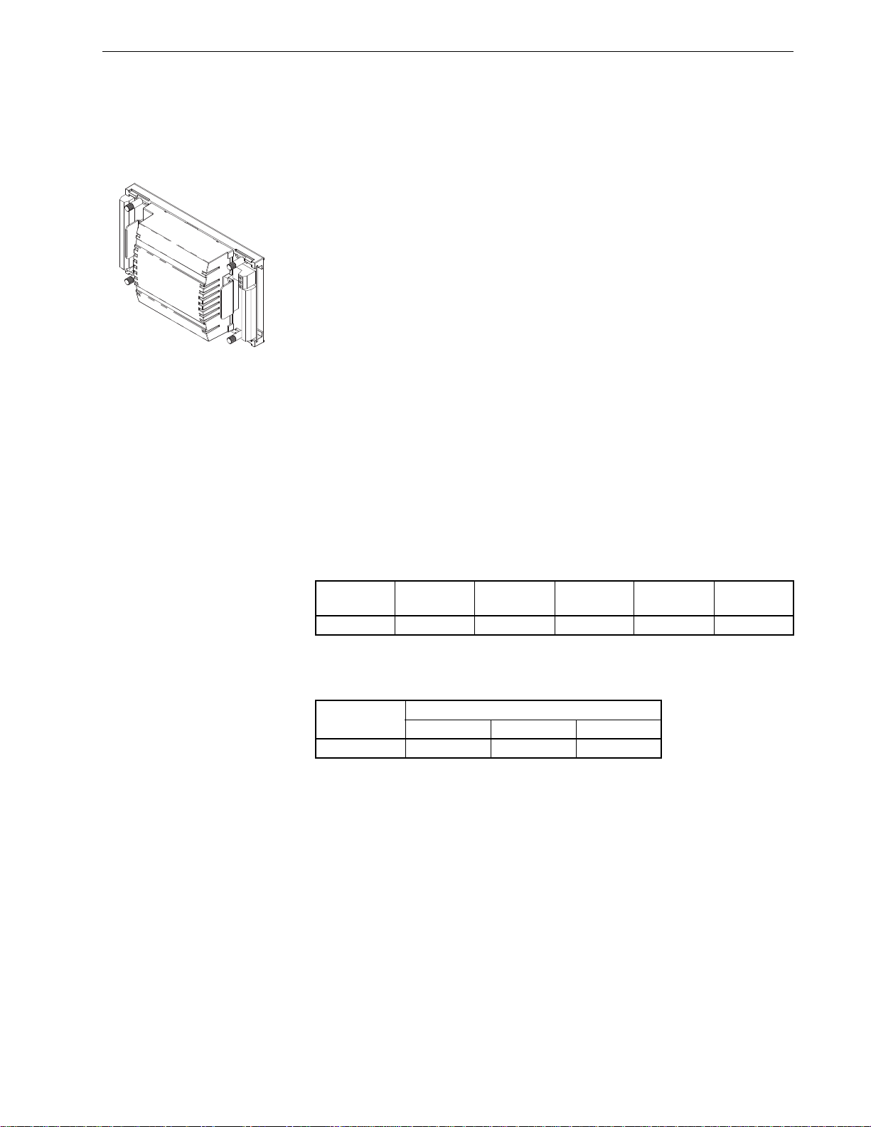
MNB-300 Unitary Controller
The I/A Series MicroNet BACnet Unitary Controller, MNB-300, is an
interoperable controller with native BACnet MS/TP communications support.
The controller features Sensor Link (S-Link) support, LED status and output
indication, screw terminal blocks, as well as a panel-mou nt su b- base w ith
removable electronics module. The MNB-300 also includes one end-of-line
(EOL) termination and two bias resistors, both of which are
jumper-selectable.
When programmed using WP Tech, the MNB-300 provides a wide range of
control strategies for packaged rooftop, heat pump, fan coil, unit ventilator,
and similar applications.
Unique Features
In addition to common MicroNet BACnet controller features ("Common
Controller Features" on page 2), the MNB-300 offers the following:
• Removable electronics module that mates with panel-mounted subbase.
• Optional NEMA 1 enclosure.
• IAM button for BACnet “I am” message broadcast.
• Integral MS/TP jack for direct connection of a PC with the WP Tech.
• Removable terminals for power and communications, to facilitate
commissioning.
• LED indication of UO and TO state.
Memory Available
T able–1.1 MNB-300 Available Memory.
Model
Number
MNB-300 256 KB 8 KB n/a 4 KB 8 KB
Physical I/O Points
T able–1.2 MNB-300 Inputs and Output s.
Model
Number
MNB-300 636
Refer to "Input and Output Spe cifications" on page 15 for a detailed
discussion of each input or output type.
Time Clock
The
MNB-300 controller uses a software clock. This software clock defaults to
a predefined Date/Time following a reset.
Flash SRAM SDRAM EEPROM FRAM
Inputs and Outputs
UI UO DO (Triac)
F-27360-11 MicroNet BACnet Wiring, Networking, and Best Practices Guide 3
Page 18
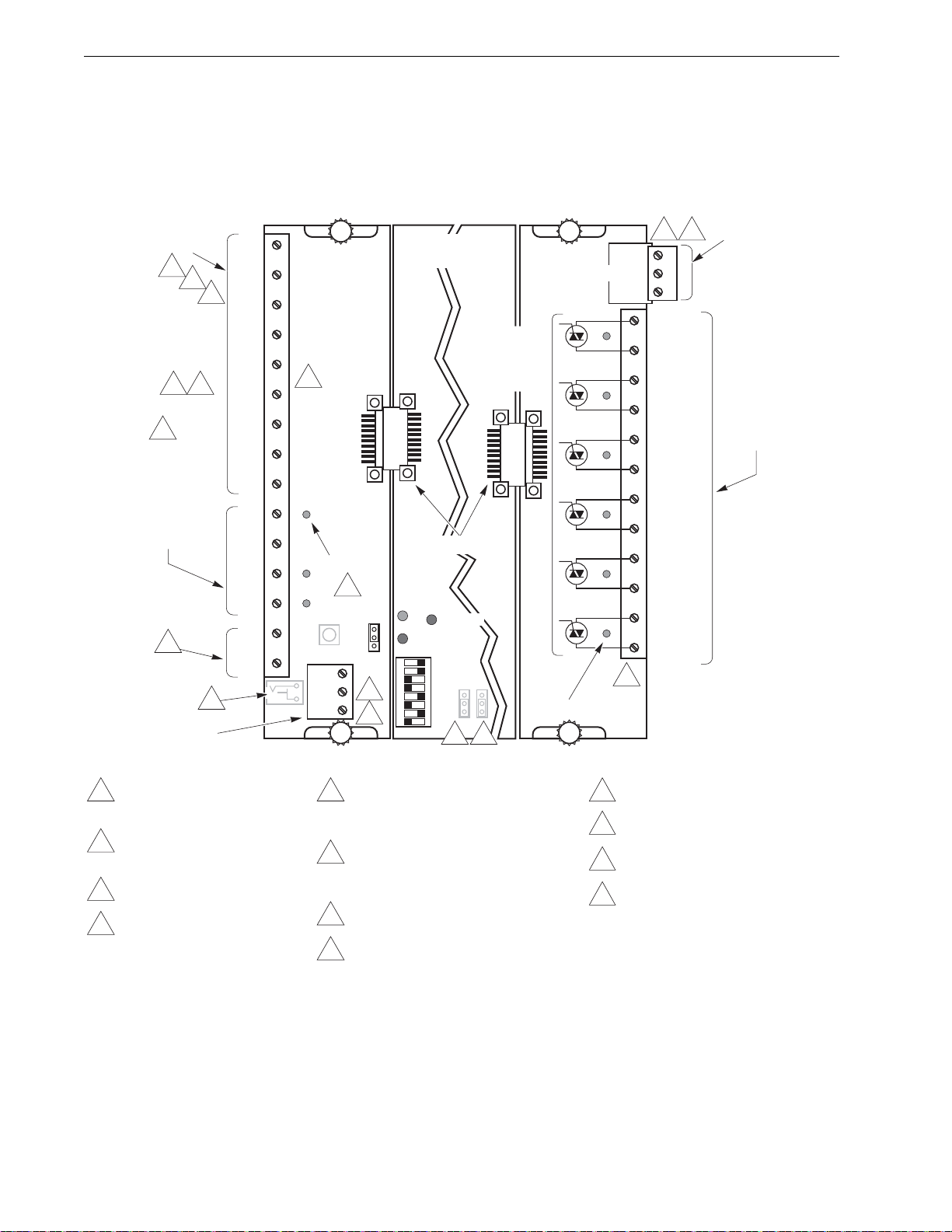
Chapter 1
MS/TP Jack
EOL
Enable
Disable
TO1 (DO1)
C1
TO2 (DO2)
C2
TO3 (DO3)
C3
TO4 (DO4)
C4
TO5 (DO5)
C5
TO6 (DO6)
C6
UI1
COM
UI2
UI3
COM
UI4
UI5
COM
UI6
UO1
COM
UO2
UO3
COM
S-LK
IAM
MS+
MS-
SLD
MSB
LSB
MNB-300
Unitary Controller
24H
24G COM
GND
XMT
RCV
STATUS
Physical
Address
EN DIS
MS BIAS
Note: Components are
shown in their
approximate locations.
Universal Inputs
0 to 5 Vdc
0 to 20 mA
10K Thermistor
1K Balco
1K Platinum
1K Resistive
10K Resistive
Digital (dry switched
contact)
Standard Pulse
Fast Pulse (UI1)
Universal Outputs
0 to 20 mA into an
80 to 550
ohm load
S-LK
Supports one
TAC I/A Series
MN-Sxxx Sensor
BACnet Network
MS/TP Communications
AC Power
20.4 to 30 Vac
50/60 Hz
Class 2 (EN 60742)
16 VA per controller
Digital Outputs
(Triac)
12 VA at 24 Vac,
50/60 Hz. Each Triac
output individually
isolated from AC
input and other I/O.
Class 2
2
5
6
4
7 8
10
12
13
1
11
3
9
2 3
2
1 Do not exceed two AWG #24
(0.205 mm
2
) wires per MS/TP
wiring terminal.
2 Power and I/O point wiring
terminals accept up to two AWG
#14 (2.08 mm
2
) or smaller wires.
3 Power and MS/TP connectors
have removable screw terminals
.
4 Input signals of 1 to 11 Vdc must
be converted to 0.45 to 5 Vdc with
a voltage divider, part number
AD-8961-220.
5 In applications requiring universal
inputs with ranges of 0 to 20 mA,
a 250 ohm
shunt resistor kit, part
number AD-8969-202, is needed.
6 An 11 kilohm shunt resistor kit, part
number AD-8969-206, is required for a
10 kilohm Thermistor Sensor (non-850
series) universal inputs.
7 To detect a closed switch, resistance must
be less than 300
ohm
.
8 To detect an open switch, resistance must
be greater than 2.5
kilohm
.
9 External load is not required to illuminate
UO LEDs.
10 Minimum rate of 1 pulse per 4 minutes.
Maximum rate of 1 pulse per second.
11 MS/TP network bias resistors are shipped
in the disabled setting, and are located
under the controller’s cover.
12 Minimum rate of 1 pulse per 4 minutes.
Maximum rate of 10 pulses per second.
13 When making an MS/TP cable, use a
1.3 x 3.5 mm Vdc power plug with strain
relief (Vimex part number
SCP-2009A-T, TAC part number
E24-1442, or equivalent). The cable
should be no longer than 6 ft. Connect
MS+ to the center contact and MS– to
the outside contact:
Note: The MS/TP cable
described above is
available from
Schneider-Electric as
MNB-CT-CBL. Contact
Schneider-Electric for
more information.
TO (DO) LEDs (6)
UO LEDs (3)
Internal
Triac
Switches
(Isolated)
Connectors (2)
+
_
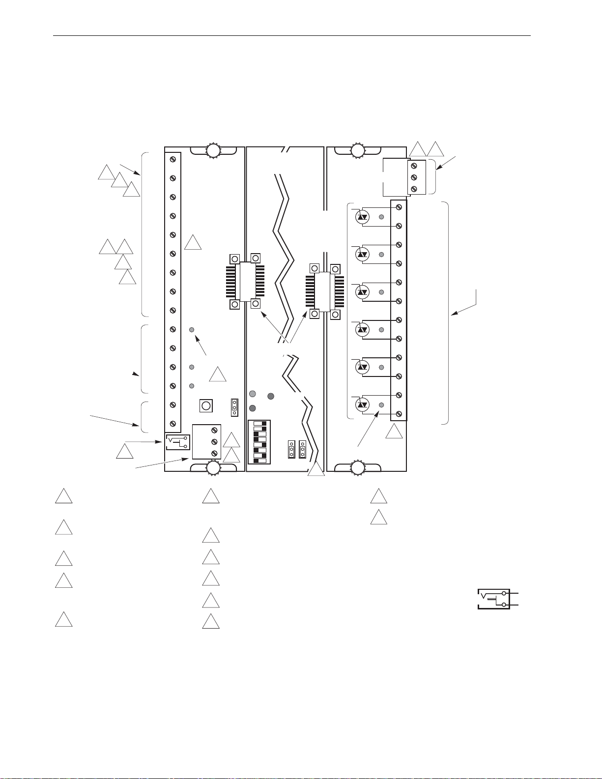
Figure–1.1 MNB-300 Terminal Connections.
Wiring Terminals
Refer to Figure-1.1 for the power and network communications wiring connections
available on the MNB-300 controller.
4 MicroNet BACnet Wiring, Networking, and Best Practices Guide F-27360-11
Page 19
I/A Series BACnet Hardware
SW24H1
SW24H2
SW24H3
24H
24G(COM)
GND
STATUS
MSTP RCV
MSTP XMT
UO 1
COM
UI 1
COM
UI 2
UI 3
S-LK/COM
MSTP +
SHLD
MSTP -
MNB-V1, MNB-V2 VAV Controllers
The I/A Series MicroNet BACnet VAV (Variable Air Volume) Controllers,
MNB-V1 and MNB-V2, are interoperable controllers with native BACnet
MS/TP communications support. Both models incor p or at e: an inte gr a l
actuator with manual override; an integral, patented, pressure transducer;
three universal inputs; Sensor Link (S-Link) support; LED st atus indication;
and over-the-shaft damper mounting. The MNB-V1 controller is designed
specifically for cooling applications, while the MNB-V2 controller adds digital
and universal outputs that make it suitable for additional VAV applications.
When programmed using WP Tech, these controllers provide a wide range
of control strategies for pressure-dependent and pressure-independent
terminal boxes, with or without reheat capabilities.
Unique Features
In addition to common MicroNet BACnet controller features ("Common
Controller Features" on page 2), the MNB-V1 and MNB-V2 offer the
following:
• Air balancing performed using WorkPlace Flow Balance Tool (WPFBT).
• Integrated packaging with actuator, pressure transducer, and controller.
• Integral actuator features manual override and travel limit stops for easy
set up and adjustment.
• Enclosure approved for use in air plenums.
• Damper position feedback to the BACnet Building Automation System
(BAS) via integral hall effect sensor.
• Stable flow control down to 0.004 in. W.C. (0.996 Pa) differential
pressure.
Memory Available
Table–1.3 MNB-Vx Available Memory.
Model
Number
MNB-V1
MNB-V2
Flash SRAM SDRAM EEPROM FRAM
256 KB 8 KB n/a 4 KB n/a
Physical I/O Points
Table–1.4 MNB-Vx Inputs and Outputs.
Model
Number
Inputs and Outputs
UI UO DO (Triac)
MNB-V1 300
MNB-V2 313
Refer to the "Input and Output Specifications" on page 15 for a detailed
discussion of each input or output type.
Time Clock
The
MNB-V1 and MNB-V2 controllers use a software clock. This software clock
defaults to a predefined Date/Time following a reset.
F-27360-11 MicroNet BACnet Wiring, Networking, and Best Practices Guide 5
Page 20
Chapter 1
UO1*
COM*
UI1
COM
UI2
UI3
S-LK/COM
S-LK
MSTP +
MSTP –
SHLD
SW24H1* (DO1)
SW24H2* (DO2)
SW24H3* (DO3)
24H
24G (COM)
GND
MSTP RCV
MSTP XMT
STATUS
Physical
Address
MSB
LSB
MNB-V1 / -V2
Controllers
MS/TP Jack
6 To detect an open switch, minimum resistance must be
greater than 2.5 kilohm.
7 Minimum rate of 1 pulse per 4 minutes. Maximum rate of
1 pulse per second.
8 When making an MS/TP cable, use a 1.3 x 3.5 mm Vdc
power plug with strain relief (Vimex part number
SCP-2009A-T, Schneider-Electric part number E24-1442,
or equivalent). The cable should be no longer than 6 ft.
Connect MS+ to the center contact and MS– to the
outside contact:
Note: The MS/TP cable described above
is available from Schneider-Electric as
MNB-CT-CBL. Contact
Schneider-Electric for more information.
1 Fixed screw terminals that accept a single AWG #14
(2.08 mm
2
) wire or up to two AWG #18 (0.823 mm2) or
smaller wires. Do not exceed two AWG #24 (0.205 mm
2
)
wires per MS/TP wiring terminal.
2 Input signals of 1 to 11 Vdc must be converted to 0.45 to
5 Vdc with a voltage divider, part number AD-8961-220.
3 In applications requiring universal inputs with ranges of
0 to 20 mA, a 250 ohm shunt resistor kit,
AD-8969-202, is needed.
4 An 11 kilohm shunt resistor kit, AD-8969-206, is
required for a 10 kilohm
Thermistor Sensor (non-850
series) universal inputs.
5 To detect a closed switch, maximum resistance must
be less than 300 ohm.
AC Power
20.4 to 30 Vac,
50/60 Hz
Class 2 (EN 60742)
15 VA per controller
plus DO load
Digital Outputs
Total 24 VA (DO1+DO2),
12 VA (DO3) at 24 Vac,
50/60 Hz, Class 2.
Pilot Duty
Universal Output
0 to 20mA into an
80 to 550
ohm
load
S-LK
Supports one I/A
Series MN-Sxxx
Sensor
BACnet Network
Communications
8
1
1
2
3
4
5 6
7
Universal Inputs
0 to 5 Vdc
0 to 20 mA
10K Thermistor
1K Balco
1K Platinum
1K Resistive
10K Resistive
Digital (dry switched
contact)
Standard Pulse
Internal Triac
Switches (3)
+
_
Note: Components are shown in
their approximate locations.
Note: Asterisks (*) indicate terminals
that apply to the MNB-V2
controller but not to the MNB-V1.
Figure–1.2 MNB-Vx Terminal Connections.
Wiring Terminals
Refer to Figure-1.2 for the power and network communications wiring connections
available on the MNB-V1 and MNB-V2 controllers.
6 MicroNet BACnet Wiring, Networking, and Best Practices Guide F-27360-11
Page 21
I/A Series BACnet Hardware
MNB-70 Zone Controllers
SW24H1
SW24H2
SW24H3
24H
24G(COM)
GND
STATUS
MSTP RCV
MSTP XMT
UO 1
COM
UI 1
COM
UI 2
UI 3
S-LK/COM
MSTP +
MSTP -
SHLD
AO
The I/A Series MicroNet BACnet Zone Controller, MNB-70, is an
interoperable controller with native BACnet MS/TP communications support.
The controller features: three universal inputs; one universal output; three
digital (Triac) outputs; Sensor Link (S-Link) support; LED status indication;
and screw terminal blocks.
When programmed using WP Tech, the MNB-70 provides a wide range of
control strategies for heat pump, fan coil, unit ventilator, mixing boxes, and
similar applications.
Unique Features
In addition to common MicroNet BACnet controller features ("Common
Controller Features" on page 2), the MNB-70 offers the following:
• I-Am button for BACnet “I-am” message broadcast.
• Integral MS/TP jack for direct connection of a PC with the WP Tech.
• Small footprint.
• Enclosure approved for use in air plenums.
Memory Available
Table–1.5 MNB-70 Available Memory.
Model
Number
MNB-70 256 KB 8 KB n/a 4 KB n/a
Flash SRAM SDRAM EEPROM FRAM
Physical I/O Points
Table–1.6 MNB-70 Inputs and Outputs.
Model
Number
Inputs and Outputs
UI UO DO (Triac)
MNB-70 313
Refer to the "Input and Output Specifications" on page 15 for a detailed
discussion of each input or output type.
Time Clock
The
MNB-70 controller uses a software clock. This software clock defaults to a
predefined Date/Time following a reset.
F-27360-11 MicroNet BACnet Wiring, Networking, and Best Practices Guide 7
Page 22
Chapter 1
UO1
COM
UI1
COM
UI2
UI3
S-LK/COM
S-LK
MSTP +
MSTP –
SHLD
SW24H1 (DO1)
SW24H2 (DO2)
SW24H3 (DO3)
24H
24G (COM)
GND
MSTP RCV
MSTP XMT
STATUS
Physical
Address
MSB
LSB
MNB-70
Controller
MS/TP Jack
IAM
1 Fixed screw terminals that accept a single AWG #14
(2.08 mm
2
) wire or up to two AWG #18 (0.823 mm2) or
smaller wires. Do not exceed two AWG #24 (0.205 mm
2
)
wires per MS/TP wiring terminal.
2 Input signals of 1 to 11 Vdc must be converted to 0.45 to
5 Vdc with a voltage divider, part number AD-8961-220.
3 In applications requiring universal inputs with ranges of
0 to 20 mA, a 250 ohm shunt resistor kit,
AD-8969-202, is needed.
4 An 11
kil
ohm shunt resistor kit, AD-8969-206, is
required for a 10
kilohm
Thermistor Sensor (non-850
series) universal inputs.
5 To detect a closed switch, maximum resistance must
be less than 300 ohm.
AC Power
20.4 to 30 Vac,
50/60 Hz
Class 2 (EN 60742)
15 VA per controller
plus DO load
Digital Outputs
Total 24 VA (DO1+DO2),
12 VA (DO3) at 24 Vac,
50/60 Hz, Class 2.
Pilot Duty
Universal Output
0 to 20mA into an
80 to 550
ohm
load
S-LK
Supports one I/A
Series MN-Sxxx
Sensor
BACnet Network
Communications
8
1
1
2
3
4
5 6
7
Universal Inputs
0 to 5 Vdc
0 to 20 mA
10K Thermistor
1K Balco
1K Platinum
1K Resistive
10K Resistive
Digital (dry switched
contact)
Standard Pulse
Internal Triac
Switches (3)
6 To detect an open switch, minimum resistance must be
greater than 2.5
kilo
hm.
7 Minimum rate of 1 pulse per 4 minutes. Maximum rate of
1 pulse per second.
8 When making an MS/TP cable, use a 1.3 x 3.5 mm Vdc
power plug with strain relief (Vimex part number
SCP-2009A-T, Schneider-Electric part number E24-1442,
or equivalent). The cable should be no longer than 6 ft.
Connect MS+ to the center contact and MS– to the
outside contact:
Note: The MS/TP cable described above
is available from Schneider-Electric as
MNB-CT-CBL. Contact
Schneider-Electric for more information.
+
_
Note: Components are shown in
their approximate locations.
Figure–1.3 MNB-70 Terminal Connections.
Wiring Terminals
Refer to Figure-1.3 for the power and network communications wiring connections
available on the MNB-70 controller.
8 MicroNet BACnet Wiring, Networking, and Best Practices Guide F-27360-11
Page 23
I/A Series BACnet Hardware
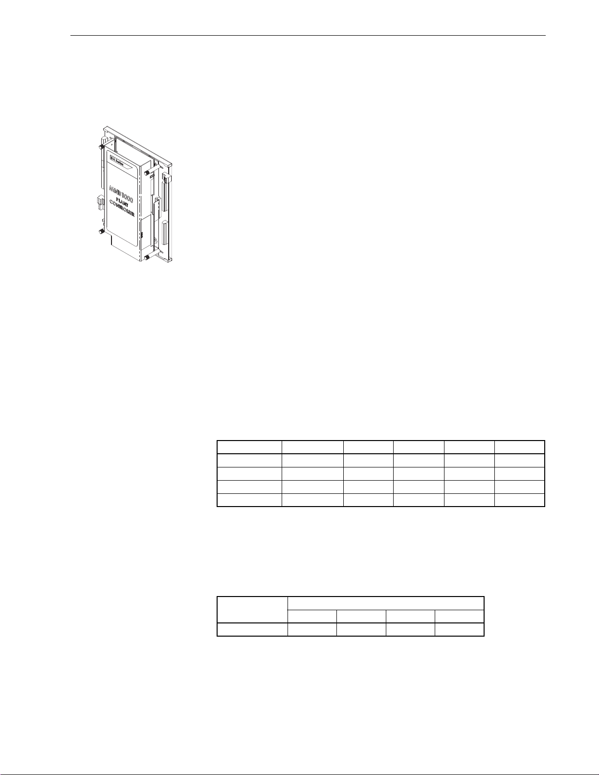
MNB-1000 Plant Controller
The I/A Series MicroNet BACnet Plant Controller, MNB-1000, is an
interoperable controller with native BACnet MS/TP communications support.
The controller features Sensor Link (S-Link) support, LED status and output
indication, two Ethernet ports, and screw terminal blocks.
The MNB-1000’s sequence of operation and BACnet image are fully
programmable using WP Tech, and can be applied to a wide range of
mechanical equipment. Typical applications include central station air
handlers, VAV air handlers, and cooling towers.
Unique Features
In addition to common MicroNet BACnet controller features ("Common
Controller Features" on page 2), the MNB-1000 offers the following:
• Optional NEMA 1 enclosure.
• IAM button for BACnet “I am” message broadcast.
• Integral MS/TP jack for direct connection of a PC with the WP Tech.
• LED indication of Ethernet communication link and activity, DO state,
UO state, and remote I/O communications.
• Application-programmable LED provides on/off indication of a
user-defined application parameter.
• BACnet router functionality.
• Support for remote I/O modules.
• Etherne t po rt bridgin g.
• 20 Vdc output
• 72 hour, battery-backed real time clock.
Memory Available
Table–1.7 MNB-1000 Available Memory.
Component Flash SRAM SDRAM EEPROM FRAM
µC 128 KB 4 KB n/a 4KB n/a
Motherboard n/a 256 KB n/a 128 KB n/a
Engine (Core) 32 or 16 MB
Engine (Boot) 2 MB n/a n/a n/a n/a
a. MNB-1000s with a date code prior to 0726 have 32 MB of core memory. Beginning with
date code 0726, core memory was changed to 16 MB. However, because the MNB-1000
has always used only the first 16 MB of memory, this change has no impact on the
controller’s operation, the size of the application allowed, or the controller’s application
compatibility.
Physical I/O Points
Table–1.8 MNB-1000 Inputs and Outputs.
Model
MNB-1000 12488
Refer to the "Input and Output Specifications" on page 15 for a detailed
discussion of each input or output type.
a
n/a 64 MB 1 Kb n/a
Inputs and Outputs
UI DI UO DO (Triac)
F-27360-11 MicroNet BACnet Wiring, Networking, and Best Practices Guide 9
Page 24

Chapter 1
Note: The onboard I/O points of the MNB-1000 can be greatly expanded
with the addition of one to eight MNB-1000-15 remote I/O modules, each of
which adds 15 I/O points. Refer to "MNB-1000-15 Remote I/O Module" on
page 13.
Time Clock
The MNB-1000 features an onboard, real-time clock. A lithium battery
provides backup power for up to 72 hours in the event of a primary power
interruption. The real-time clock acts as a Date/Time server using native
BACnet services. In the absence of another Date/Time server on the
network, the MNB-1000 can provide this functionality to other nodes on the
BACnet internetwork.
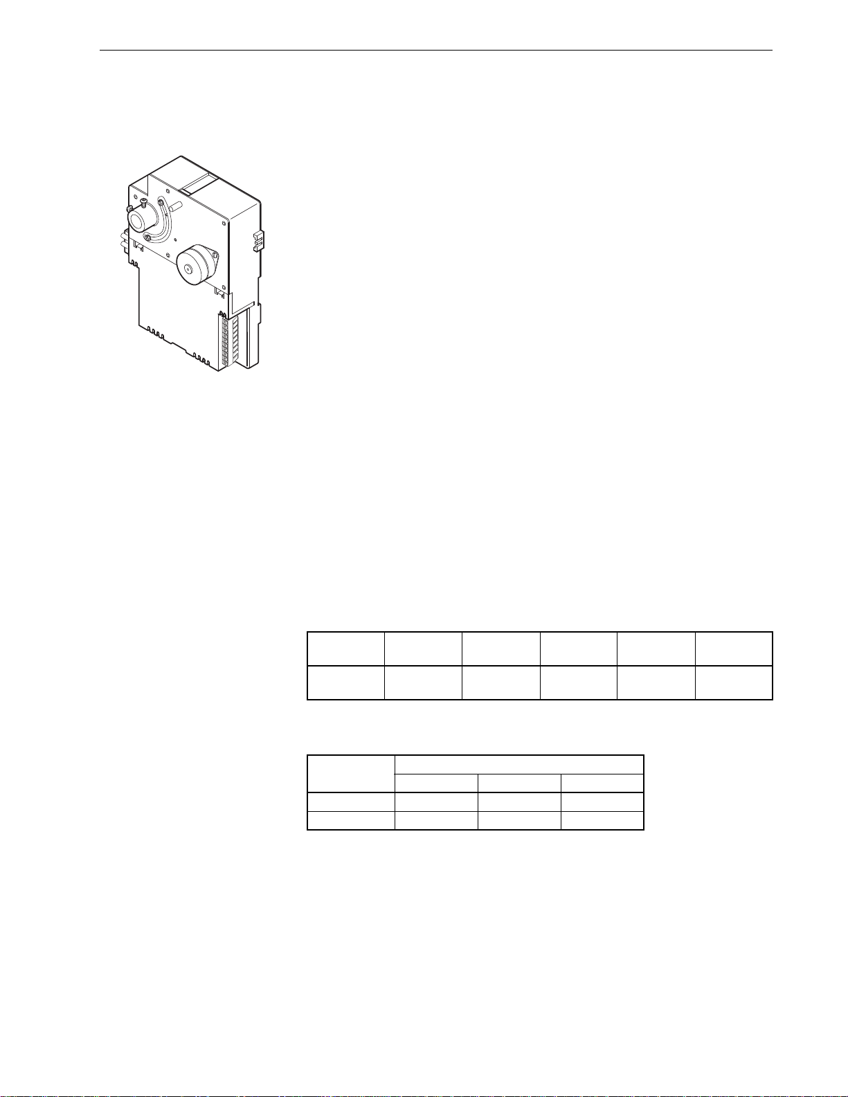
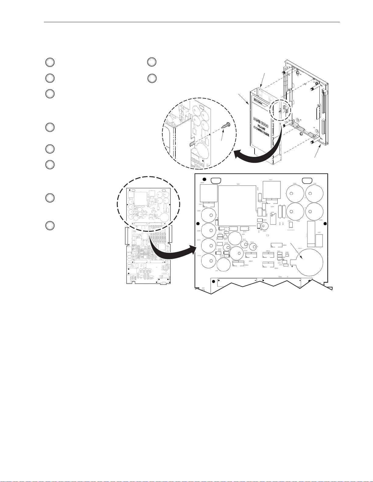
Battery Replacement
If the real-time clock’s battery becomes depleted, replace it with lithi um
battery, part number E17-137, according to the instructions in Figure-1.4.
For additional disassembly and reassembly instructions, refer to MicroNet
BACnet MNB-1000 Plant Controller Installation Instructions, F-27347
Caution: Follow static discharge precautions when hand ling the MNB-1000
and its component parts.
Note: Whenever the battery is removed from the MNB-1000, the clock
setting and volatile data will be lost. Reprogram the MNB-1000 as needed
after installing the replacement battery.
10 MicroNet BACnet Wiring, Networking, and Best Practices Guide F-27360-11
Page 25
I/A Series BACnet Hardware
Printed Circuit Board
Cover
Base Plate
Printed Circuit
Board
Screw
(1 of 2)
Lithium Battery
E17-137
1 If the controller is mounted inside an
enclosure, open the enclosure cover.
2 Remove power from the
controller.
3 Referring to MicroNet BACnet
MNB-1000 Controller Installation
Instructions, F-27347, remove
the controller’s main assembly
from the base plate.
4 Remove two screws, and then
separate the printed circuit
board from the cover.
5 Locate the battery on the printed
circuit board.
6 Remove the depleted battery,
and then install a new lithium
battery, part number E17-137.
Make sure that the positive (+)
side faces upward.
7 Reassemble the printed
circuit board to the cover,
and secure with the two
screws removed in step 4.
8 Referring to F-27347,
reassemble the
controller’s main
assembly to the base
plate.
9 Restore power to the controller.
10 If applicable, close the enclosure
cover.
Figure–1.4 MNB-1000 Real-time Clock Battery Replacement.
F-27360-11 MicroNet BACnet Wiring, Networking, and Best Practices Guide 11
Page 26

Chapter 1
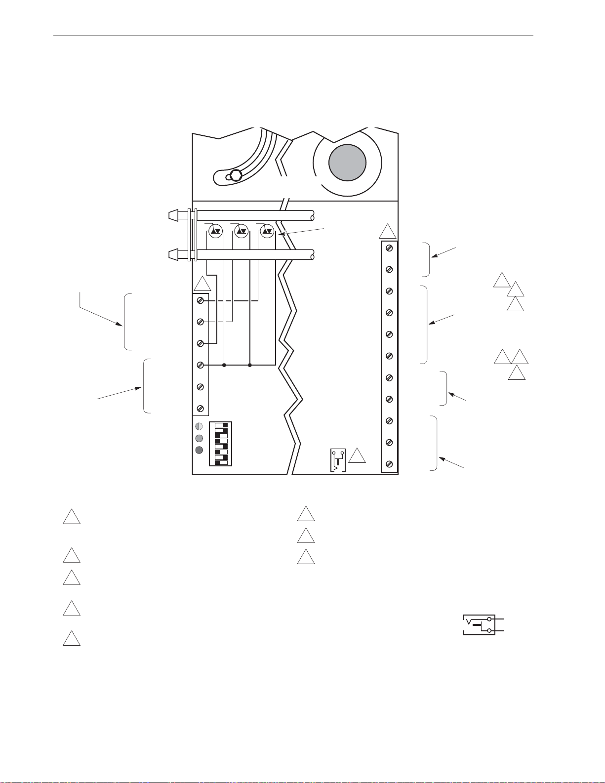
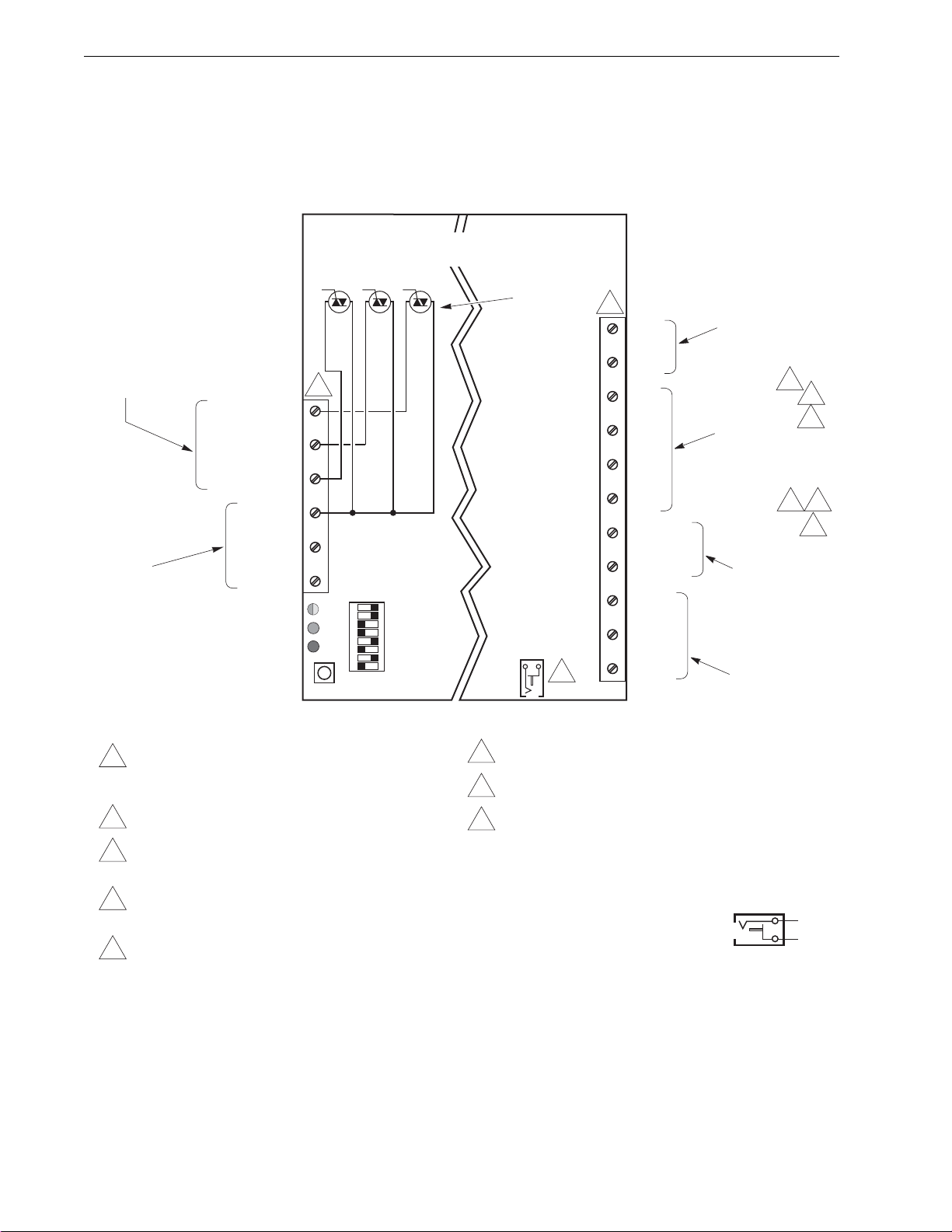
Figure–1.5 MNB-1000 Terminal Connections.
Wiring Terminals
Refer to Figure-1.5 for the wiring connections available on the MNB-1000 controller.
20 Vdc Output
±10% at
20 Vdc
100 mA
Universal Inputs
0 to 5 Vdc
0 to 20 mA
4
5
10K Thermistor
1K Balco
1K Platinum
1K Resistive
10K Resistive
Digital (dry switched
contact)
9
7
Digital Inputs
Dry Switched
Contact
Fast Pulse
12
10
7
Local Display
(for future use)
S-LK
Supports one I/A
Series MN-Sxxx
Sensor
ADI or
Remote I/O
BACnet Network
Communications
1 I/O point wiring terminals
accept a single AWG #14
(2.08 mm
2
) or up to two
AWG #18 (0.823 mm2) or
20V
UI1
COM
UI2
UI3
COM
UI4
UI5
6
COM
UI6
UI7
COM
UI8
UI9
COM
UI10
UI11
COM
UI12
DI1
COM
DI2
DI3
COM
DI4
LD
COM
S-LK
IO+
IO-
31
31
SLD
MS+
MS-
SLD
Note: Components are
1
8
Disable Enable
13
I AM
MS/TP Jack
shown in their
approximate
locations.
0 PORT
IO EOL
MS BIAS
MS EOL
MS BIAS
ACT LNK
1 PORT
Physical
Address
Plant Controller
smaller wires. Do not
exceed two AWG #24
(0.205 mm
2
) wires per
MS/TP or Remote I/O
wiring terminal.
2 Power wiring terminals accept up to two AWG #14
(2.08 mm
2
) or smaller wires.
3 Power, MS/TP, and Remote I/O connectors have
removable screw terminals.
4 Input signals of 1 to 11 Vdc must be converted to 0.45 to
5 Vdc with a voltage divider, part number AD-8961-220.
5 In applications requiring universal inputs with ranges of 0 to
20 mA, a 250
ohm
shunt resistor kit, AD8969-202, is
needed.
6 An 11 kil
for a 10 kil
ohm
shunt resistor kit, AD-8969-206, is required
ohm
thermistor Sensor (non-850 series)
universal inputs.
MNB-1000
Internal Triac
Switches (8)
(Isolated)
TO (DO)
LEDs (8)
24H
24G COM
GND
1
TO1 (DO1)
C1
TO2 (DO2)
C2
TO3 (DO3)
C3
TO4 (DO4)
C4
TO5 (DO5)
C5
TO6 (DO6)
C6
TO7 (DO7)
C7
TO8 (DO8)
C8
2 3
AC Power
20.4 to 30 Vac
50/60 Hz
Class 2 (EN 60742)
50 VA per controller
Isolated from I/O
Digital Outputs
12 VA at 24 Vac,
50/60 Hz each Triac
output individually
isolated from AC
input and other I/O.
1
Universal Outputs
0 to 20 mA into an
80 to 550 ohm
load.
7 To detect a closed
switch, maximum
resistance must be
less than 300
8 Remote I/O network
bias resistor is built-in.
minimum resistance must be
greater than 2.5 kil
ETHERNET
LSB
UO LEDs (8)
RCV
XMT
IO
MSTP
STATUS AUX
11
UO1
COM
UO2
UO3
COM
UO4
UO5
COM
UO6
UO7
COM
UO8
9 To detect an open switch,
10 To detect an open switch,
minimum resistance must
be equal to or greater than
2.5 kil
MSB
ohm
11 External load is required to
illuminate UO LEDs.
12 Minimum rate of 1 pulse per 4 minutes. Maximum rate of 10 pulses
per second. With digital inputs only.
13 When making an MS/TP cable, use a 1.3 x 3.5 mm Vdc power
plug with strain relief (Vimex part number SCP-2009A-T,
Schneider-Electric part number E24-1442, or equivalent). The
cable should be no longer than 6 ft. Connect MS+ to the center
contact and MS– to the outside contact:
–
Note: The MS/TP cable described above
is available from Schneider-Electric as
MNB-CT-CBL. Contact
+
Schneider-Electric for more information.
ohm
.
ohm
.
.
12 MicroNet BACnet Wiring, Networking, and Best Practices Guide F-27360-11
Page 27

I/A Series BACnet Hardware
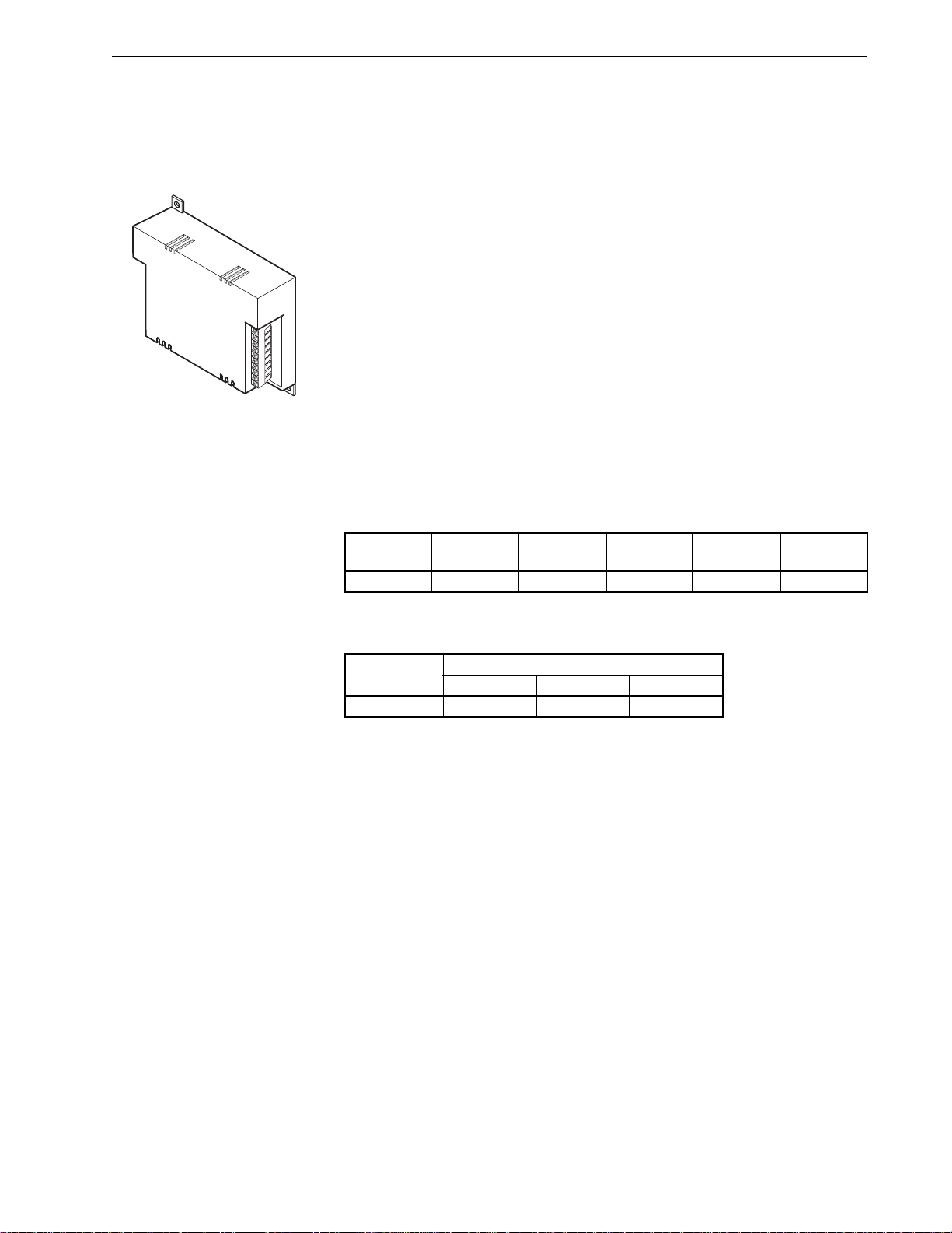
MNB-1000-15 Remote I/O Module
The I/A Series MicroNet BACnet Remote I/O Module, MNB-1000-15, is
designed to be connected to an MNB-1000 Plant Controller, so as to expand
the controller’s I/O count. When programmed using WP Tech, each module
increases the count by 15 inputs and outputs. Up to ei ght modules can be
connected to a given MNB-1000, for a potential increase of 120 I/O points,
total. In this way, the controller’s existing 32 onboard I/O can be e xpanded to
47 I/O points (with one module), up to a maximum total of 152 I/O points
(with eight modules).
Features
The MNB-1000-15 offers the following:
• 24 Vac powered.
• DIP switch for setting the physical address on the remote I/O network.
• Isolated EIA-485 (formerly RS-485) transceiver for remote I/O
communications.
• Removable electronics module that mates with panel-mounted subbase.
• Optional NEMA 1 enclosure.
• Removable terminals for power and communications, to facilitate
commissioning.
• LED indication of compatibility, UO and TO state, and communication
state (with the MNB-1000).
• Firmware upgradeable over the network.
• Fallback function, in case of loss of communication with MNB-1000.
Note: The MNB-1000-15 does not support the S-Link bus.
Memory Available
Table–1.9 MNB-1000-15 Available Memory.
Model
Number
MNB-1000-15 256KB 8KB n/a 4KB 8KB
Physical I/O Points
T able–1.10 MNB-1000-15 Inputs and Outputs.
Model
Number
MNB-1000-15 636
Refer to "Input and Output Spe cifications" on page 15 for a detailed
discussion of each input or output type.
Fallback Function
The MNB-1000-15 module’s outputs are driven directly by the MNB-1000
Plant Controller, in which the application resides. If communications
between the module and the MNB-1000 is lost, the module’s output s are set
to fallback values that were previously sent to the module during normal
communications. Refer to "Fallback Function" on page 107 for more
information on this function.
Flash SRAM SDRAM EEPROM FRAM
Inputs and Outputs
UI UO DO (Triac)
F-27360-11 MicroNet BACnet Wiring, Networking, and Best Practices Guide 13
Page 28
Chapter 1
EOL
Enable
Disable
TO1 (DO1)
C1
TO2 (DO2)
C2
TO3 (DO3)
C3
TO4 (DO4)
C4
TO5 (DO5)
C5
TO6 (DO6)
C6
UI1
COM
UI2
UI3
COM
UI4
UI5
COM
UI6
UO1
COM
UO2
UO3
COM
S-LK
IO+
IO
-
SLD
MSB
LSB
MNB-1000-15
Remote I/O Module
24H
24G COM
GND
XMT
RCV
STATUS
Physical
Address
Universal Inputs
0 to 5 Vdc
0 to 20 mA
10K Thermistor
1K Balco
1K Platinum
1K Resistive
10K Resistive
Digital (dry switched
contact)
Standard Pulse
(UI1-UI6)
Universal Outputs
0 to 20 mA into an
80 to 550 ohm load
Remote I/O Network
Communications to
MNB-1000
AC Power
20.4 to 30 Vac
50/60 Hz
Class 2 (EN 60742)
16 VA per module
Digital Outputs
(Triac)
12 VA at 24 Vac,
50/60 Hz. Each Triac
output individually
isolated from AC
input and other I/O.
Class 2
2
5
6
4
7 8
10
1
3
9
2 3
2
1 Do not exceed two AWG #24
(0.205 mm
2
) wires per Remote I/O
wiring terminal.
2 Power and I/O point wiring
terminals accept up to two AWG
#14 (2.08 mm
2
) or smaller wires.
3 Power and remote I/O connectors
have removable screw terminals
.
4 Input signals of 1 to 11 Vdc must
be converted to 0.45 to 5 Vdc with
a voltage divider, part number
AD-8961-220.
5 In applications requiring universal inputs
with ranges of 0 to 20 mA, a 250 ohm
shunt resistor kit, part number
AD-8969-202, is needed.
6 An 11
kil
ohm shunt resistor kit, part
number AD-8969-206, is required for a
10
kil
ohm Thermistor Sensor (non-850
series) universal inputs.
7 To detect a closed switch, resistance must
be less than 300
ohm
.
8 To detect an open switch, resistance must
be greater than 2.5 kil
ohm
.
9 External load is not required to
illuminate UO LEDs.
10 Minimum rate of 1 pulse per 4 minutes.
Maximum rate of 1 pulse per second.
11 Items in gray, although present, are not
used in the MNB-1000-15.
12 Bias for the remote I/O network is
provided by the built-in bias resistor on
the MNB -1000 controller.
TO (DO) LEDs (6)
UO LEDs (3)
Internal
Triac
Switches
(Isolated)
Connectors (2)
11
11
11 12
Note: Components are shown
in their approximate
locations.
Figure–1.6 MNB-1000-15 Terminal Connections.
Wiring Terminals
Refer to Figure-1.6 for the power and network communications wiring
connections available on the MNB-1000-15 remote I/O module.
14 MicroNet BACnet Wiring, Networking, and Best Practices Guide F-27360-11
Page 29
I/A Series BACnet Hardware
UI1
COM
UI2
Controller
UI1
COM
UI2
+
_
250 ohm
UI1
COM
UI2
+
_
1
10 kilohm Thermistor
(with an 11 kilohm
shunt resistor)
4 to 20 mA
Transmitter
0 to 5 Vdc
Transmitter
Controller
Inputs
Controller
Inputs
Sensor Power
Source
Sensor Power
Source
1 Resistor kit, AD-8969-202. Be
sure to install the resistor at the
controller, not at the 4 to 20 mA
device.
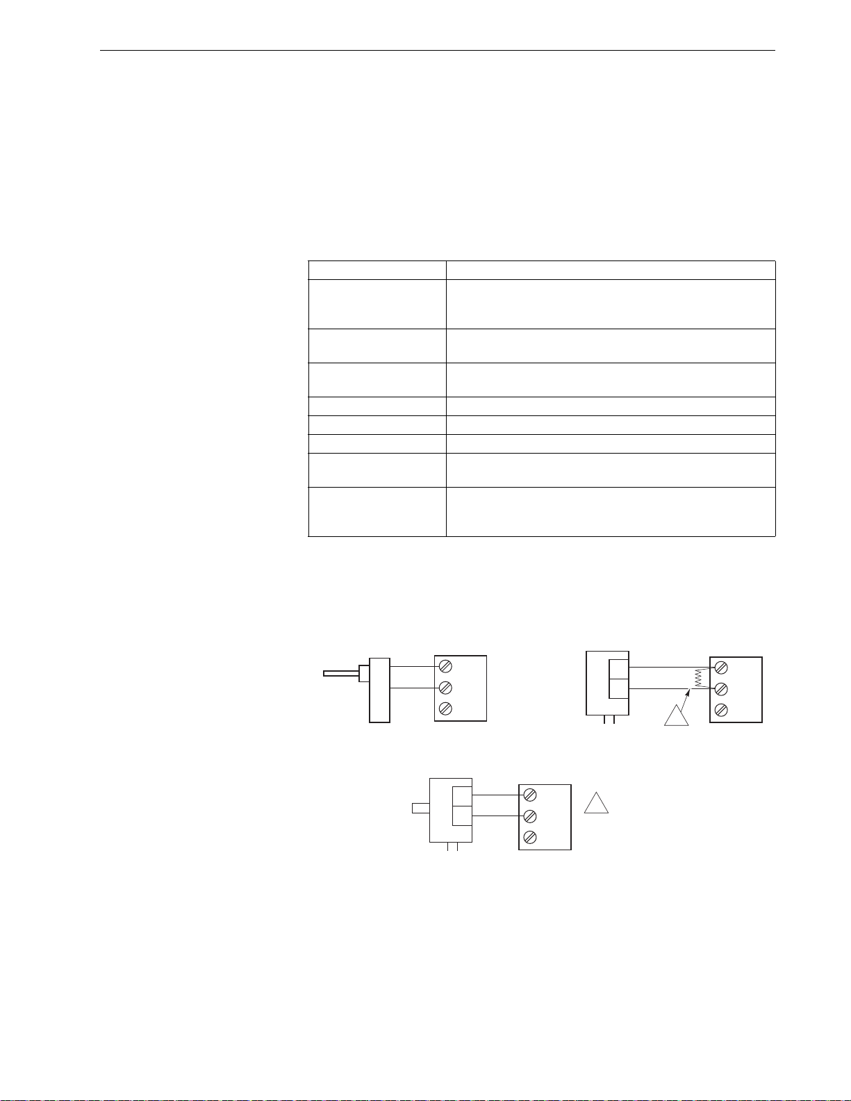
Figure–1.7 Universal Input Connections.
Input and Output Specifications
All MicroNet BACnet controllers use input and output types as described in
this section.
Universal Inputs
The universal input characteristics are software-configured to respond to
one of the eight input types listed in Table–1.11.
Table–1.11 Universal Inputs.
Input Characteristics
10 kilohm Thermistor
with 11 kilohm Shunt
Resistor
1kilohm Balco
1 kilohm Platinum
1 kilohm Resistive 0 to 1500 ohm.
10 kilohm Resistive 0 to 10.5 kilohm.
Analog Voltage Range 0 to 5 Vdc
Analog Current
Digital
Sensor operating range -40 to 250 °F (-40 to 121 ° C),
requires Schneider Electric model TSMN-57011-850
series, TS-5700-850 series, or equivalent.
-40 to 250 °F (-40 to 121 °C), Schneider Electric model
TSMN-81011, TS-8000 series, or equivalent.
-40 to 240 °F (-40 to 116 °C), Schneider Electric model
TSMN-58011, TS-5800 series, or equivalent.
0 to 20 mA, requires external 250 ohm shunt resistor kit,
AD-8969-202.
Dry switched contact; detection of closed switch requires
less than 300 ohm resistance; detection of open switch
requires more than 2.5 kilohm.
See Figure-1.7 for examples of connections to universal inputs.
F-27360-11 MicroNet BACnet Wiring, Networking, and Best Practices Guide 15
Page 30
Chapter 1
UO1
COM
UO2
+
_
500 ohm
Controller
Outputs
+
_
UO1
COM
UO2
1
2
3
1 Output accuracy degrades as input
impedance decreases.
2 Resistor kit, AM-708. Be sure to
install the resistor at the 0 to 10 Vdc
device, not at the controller.
3 Can be purchased through PS3,
part number FUN-RIBU1-C.
Controller
Outputs
4 to 20 mA
Actuator
Controller Output
Configured as
0 to 20 mA
Functional Devices
RIBU1C Relay
0 to 10 Vdc
Actuator
N/C
COM
N/O
Wht/Blu
10-30 Vdc
Wht/Yel
COM
UO1
COM
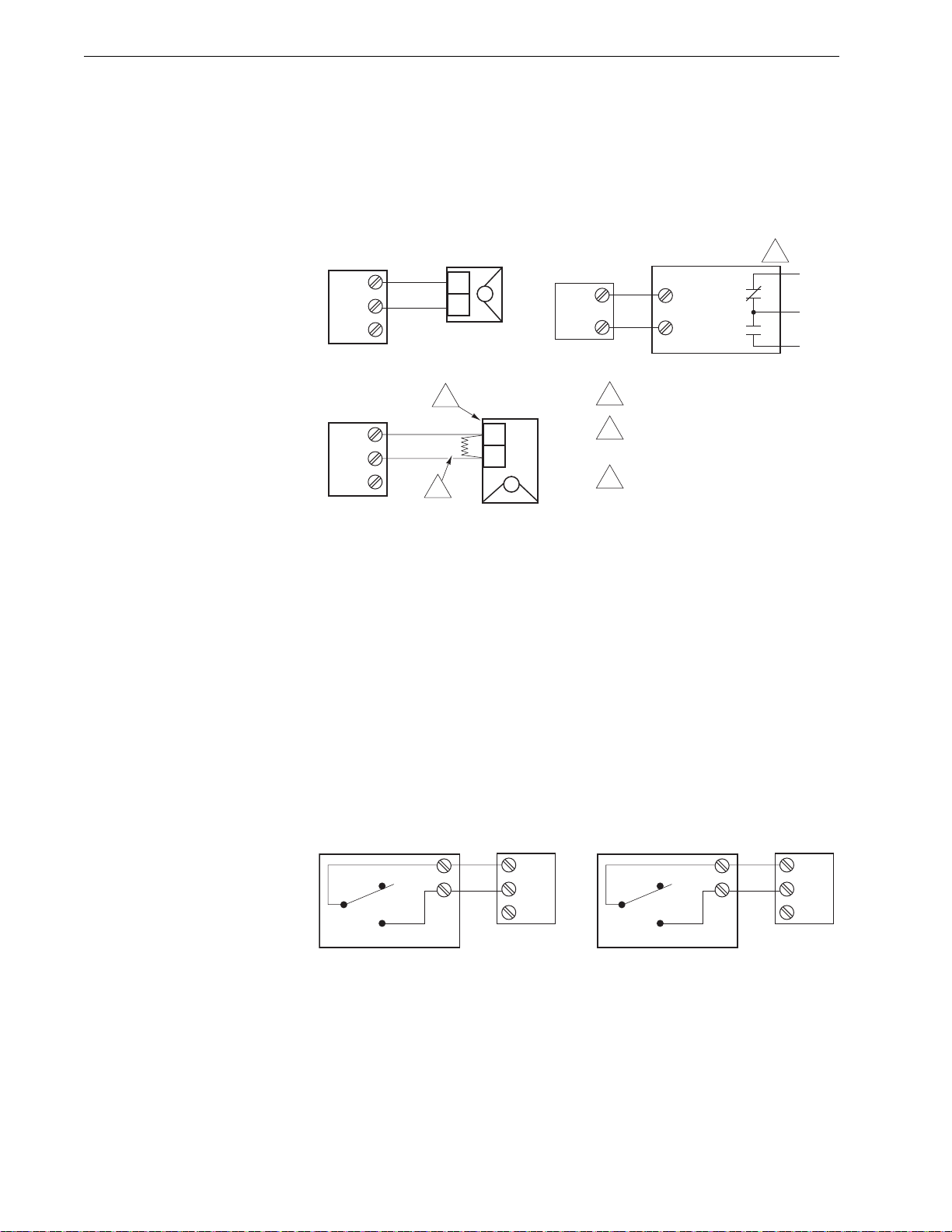
Figure–1.8 Universal Output Connections.
r
Figure–1.9 Fixed Digital Input Connections.
Universal Outputs
0 to 20 mA (output load from 80 to 550 ohm). See Figure-1.8 for examples of
connections to universal outputs.
Digital Inputs
Dry switched contact. Detection of a closed switch requires less than
300 ohm resistance. When connected to a controller’s digital inputs,
detection of an open switch requires more than 2.5 kilohm. When connected
to a controller’s universal inputs (used as digit al inputs), d etection of an open
switch requires more than 2.5 kilohm. See Figure-1.9 for examples of a
connection to digital inputs.
Connection to Digital Inputs Connection to Universal Inputs
DI Input
On-Off Type Device
NC
COM
NO
Controller
Inputs
DI1
COM
DI2
DI Input
On-Off Type Device
NC
COM
NO
Controlle
Inputs
UI1
COM
UI2
16 MicroNet BACnet Wiring, Networking, and Best Practices Guide F-27360-11
Page 31

I/A Series BACnet Hardware
Figure–1.10 MNB-V2 and MNB-70 Controller Triac Output Circuit Configuration.
GND 24H24G
SW24H1
(DO1)
SW24H2
(DO2)
SW24H3
(DO3)
Class 2
Transformer
24 Vac Primary
Load1 Load2 Load3
MNB-V2
Controller
Digital Output s, Triac
MNB-V2 and MNB-70
Table–1.12 lists specifications for the Triac outputs featured on the MNB-V2
and MNB-70 controllers.
Caution: The Triac (digital) output s o n MicroNet BACnet controller s are not
protected against short circuits. Take necessary precautions to protect these
outputs against short circuits.
Table–1.12 Digital Outputs, Triac, on MNB-V2 and MNB-70.
Input Characteristics
Internally sourced, high side switching. Triac outputs
Common Terminal
share a common supply (24H) that is independently
switched to each output terminal, SW24H1, SW24H2, and
SW24H3 (DO1, DO2, and DO3).
b
Rating (DO1+DO2)
Rating (DO3)
b
24 VA total at 24 Vac, 50/60 Hz.
12 VA at 24 Vac, 50/60 Hz.
Default Output State OFF (inactive).
a. As with all Triac devices, a high-impedance meter on the output without a load will show
24 Vac, due to low level leakage through the device.
b. As labeled on the controller, SW24H1=DO1, SW24H2=DO2, and SW24H3=DO3 (see
Figure-1.2).
a
See Figure-1.10 for an example of a connection to an MNB-V2 or MNB-70
controller’s Triac outputs.
F-27360-11 MicroNet BACnet Wiring, Networking, and Best Practices Guide 17
Page 32

Chapter 1
Figure–1.11 MNB-300 Controller , MNB-1000 Controller, and MNB-1000-15 Remote
I/O Module Triac Output Circuit Configuration.
Note: With the MNB-V2 and MNB-70, AC voltage to Triacs is sourced from
the controller . This is different fr om the MNB-300 and MNB-1000 contr ollers,
and the MNB-1000-15 module, where AC voltage is sourced externally.
MNB-300, MNB-1000, and MNB-1000-15
Table–1.13 lists specifications for the Triac outputs featured on MNB-300
and MNB-1000 controllers, and on the MNB-1000-15 remote I/O module.
Caution: The Triac (digit al) outp ut s on Mi croNet BACnet contro llers are not
protected against short circuits. Take necessary precautions to protect these
outputs against short circuits.
Table–1.13 Digital Outputs, Triac, on MNB-300, MNB-1000, and MNB-1000-15.
Input Characteristics
Isolation Each output individually isolated from circuit common.
Common Terminal
Rating 12 VA at 24 Vac, 50/60 Hz.
Default Output State OFF (inactive).
a. As with all Triac devices, a high-impedance meter on the output without a load will show
24 Vac, due to low level leakage through the device.
Each TO has its own common terminal. This is the voltage
switched to each TO output.
a
See Figure-1.11 for an example of a connection to the Triac outputs on an
MNB-300, MNB-1000, or MNB-1000-15.
24 Vac
Load1
TO1 (DO1) C1
GND
Load2
TO2 (DO2) C2
24H24G
Class 2
Transformer
24 Vac Primary
24 Vac
TOx (DOx) Cx
24 Vac
Loadx
20 Vdc Output
20 Vdc ±10% at 100 mA for supplying power to an external device. See
Figure-1.12 for an example of a connection to a 20 Vdc output.
18 MicroNet BACnet Wiring, Networking, and Best Practices Guide F-27360-11
Page 33

I/A Series BACnet Hardware
Figure–1.12 20 Vdc Output Connection.
ControllerAuxiliary Device
+
–
Humidity 4 to 20 mA
(example)
250 ohm
1
20V
UI1
COM
1 Resistor kit, AD-8969-202,
4 to 20 mA only. Not
required for Vdc.
Inputs from MN-Sx MicroNet Sensor
Table–1.14 lists specifications for the inputs from MicroNet Sensors. For an
example showing how a MicroNet Sensor may be wired to a MicroNet
BACnet controller, see Figure-1.13.
Table–1.14 Inputs from MN-Sx MicroNet Sensor.
Input Characteristics
Space Temperature 32 to 122 °F (0 to 50 °C).
Space Humidity 5 to 95% RH, non-condensing.
Local Setpoint
Override Pushbutton For standalone occupancy control.
Fan Operation and
Speed Mode
System Mode Heat, cool, off, or auto.
Emergency Heat Enable or disable.
Adjustable within limits set by application programming
tool.
On/off, speed (low/medium/high), or auto.
F-27360-11 MicroNet BACnet Wiring, Networking, and Best Practices Guide 19
Page 34

Chapter 1
Wire S-Link to terminals
1 and 2 on baseplate
1 MS/TP wiring of controller to sensor screw terminals
is optional.
Note: To preserve the integrity of the network, the
MS/TP network wiring connecting a MicroNet
BACnet controller to an MN-Sx sensor must be run
to the sensor and back, in daisychain fashion. A
wire “spur” must not be used to connect the sensor
to the controller.
2 Observe consistent polarity when wiring.
3 S-Link wiring is not polarity-sensitive.
4 Tie the MS/TP shields together at the sensor.
5 MS/TP shields must be connected to the SLD (or SHLD)
terminal of all MicroNet BACnet controllers.
6 S-Link communications is not supported in the
MNB-1000-15 remote I/O module.
To Rest of the
MS/TP Network
To Rest of the
MS/TP Network
4
5
6
S-Link
MN-Sx
Sensor
MS/TP
MS/TP Jack
+
_
12
43
S-Link Jack
1
3
2
2
Shield
Controller
COM
SLK
SLD (SHLD)
MS+ (MSTP+)
MS- (MSTP-)
Wire MS/TP to terminals
3 and 4 on baseplate
Figure–1.13 Sensor Link (S-Link) Connection.
20 MicroNet BACnet Wiring, Networking, and Best Practices Guide F-27360-11
Velocity Pressure Input
MNB-V1 and MNB-V2
Table–1.15 lists specifications for the velocity pressure inputs on MNB-Vx
controllers.
Table–1.15 Velocity Pressu re Input, on MNB-V1 and MNB-V2.
Control Range 0.004 to 1.5 in. of W.C. (0.996 to 373.5 Pa)
Over Pressure
Withstand
Accuracy
Sensor Type Self-calibrating flow sensor (differential pressure).
Tu bing Connections
Tubing Length 5 ft (1.52 m) maximum, each tube.
Input Characteristics
±20 in. of W.C. (4.980 kPa)
±5% at 1.00 in. of W.C. (249.00 Pa) with laminar flow at
77 °F (25 °C) and suitable flow station.
Barb fittings for 0.170 in. I.D. (4.3 mm I.D.) FRPE
polyethylene tubing or 0.25 in. O.D./0.125 in. I.D. (6.4 mm
O.D./3.2 mm I.D.) Tygon
taps).
®
tubing (high and low pressure
Page 35

I/A Series BACnet Hardware
MicroNet Digital Wall Sensors
Each MicroNet BACnet controller supports a single MN-Sx digital wall
sensor. 12 sensor models are presently available, six sensing zone
temperature and six sensing both zone temperature and humidity. These
range from a sensor-only model to one with seven pushbuttons and an LCD
screen. Table–1.16 provides a feature summary of the MN-Sx sensors.
Note: S-Link communications is not supported in the MNB-1000-15 remote
I/O module.
T able–1.16 MicroNet Sensors.
Sensor Model Features Sensor Model Features
MN-S1
MN-S1HT
MN-S2
MN-S2HT
MN-S3
MN-S3HT
MN-S4-FCS
MN-S4HT-FCS
No buttons
• Sensor only.
Its primary function is to provide room
temperature or humidity sensing values
to the controller via the Sensor Link.
Three buttons
• MN-S2 features—Sensor; Override key
with LED indicator.
• 3-digit LCD for showing (typically) the
current temperature.
• Up and Down keys to allow adjustment
of the current setpoint.
Six buttons
• Larger LCD capable of showing up to
four possible temperature, humidity,
and function displays
• Up and Down keys for setpoint
adjustment.
• Three fan speed selection keys:
– High Fan Speed
– Medium Fan Speed
– Low Fan Speed
• Fan On / Off / Auto key.
MN-S4
MN-S4HT
MN-S5
MN-S5HT
One button
• Sensor (as in MN-S1).
• Override key with LED indicator, to
allow the timed override of unoccupied
to occupied modes of operation.
Six buttons
• MN-S3 features—Sensor; Override key
with LED indicator; LCD temperature,
humidity, and function display (larger
than in MN-S3, capable of showing up
to four possible displays); Up and
Down keys for setpoint adjustment.
• These “sub-base” functions:
– Mode key allowing two
Heat/Cool/Auto/Off modes.
– Fan key to control fan operation or
speed.
– Setpoint key to select up to four
Heat/Cool setpoints.
Seven buttons
• MN-S4 features—Sensor; Override key
with LED indicator; larger LCD capable
of showing up to four possible
temperature, humidity, and function
displays; Up and Down keys for
setpoint adjustment; Mode key, Fan
key, and Setpoint key “sub-base”
functions.
• Emergency Heat key with LED
indicator for emergency heat activation
or indication (Heat Pump applications).
F-27360-11 MicroNet BACnet Wiring, Networking, and Best Practices Guide 21
Page 36

Chapter 1
A
Figure–1.14 MN-Sx Sensor Pre-Wirable Baseplate and Electronic Assembly .
+
+
!
Common Sensor Features
An MN-Sx sensor communicates with (and is powere d by) two Sensor Link
(S-Link) terminals on a MicroNet controller — it does not consume a typical
I/O point. The S-Link connection between the sensor and the controller can
use low-cost, twisted-pair wire up to 200 ft (61 m), and is not polarity
sensitive. All MN-Sx sensor models also include an MS/TP jack for a
convenient means of connecting a network tool, such as a Work Place Tech
Tool PC, to the BACnet network.
Under each MN-Sx sensor’s detachable cover is a pre-wirable baseplate
and a removable electronic assembly (Figure–1.14). The same baseplate is
used in all MN-Sx sensor models.
Pre-wirable Sensor
Baseplate
Removable Electronic
ssembly (contains
temperature sensor)
S-Link Screw Terminals
(1 and 2)
MS/TP Jack
Note: MN-Sx sensors have no independent intelligence. This means any
MN-Sx sensor’s behavior is defined by how the application control logic has
been engineered, compiled, and downloaded into the MicroNet controller.
This allows replacement of a sensor without need of additional
programming.
Keypad Icons Depending on the sensor model used and the control application, various
keypad buttons allow the sensor user to select or perform dif ferent functions.
Table–1.17 MicroNet Sensor Keypad Icon Definitions.
Setpoint Override
Up Emergency Heat
Down Fan On/Off or Speed
Fan Speed (MN-S4-FCS) Hi,
Mode
Med, Low
Fan On/Off Auto (MN-S4-FCS)
22 MicroNet BACnet Wiring, Networking, and Best Practices Guide F-27360-11
Page 37

I/A Series BACnet Hardware
%
Figure–1.15 MN-S5 and MN-S5HT Keypad and LCD
(Most LCD Icons Shown Illuminated).
LCD Icons Sensor models featuring an LCD typically show the current zone
temperature as a default display. The MN-S4, MN-S4HT, MN-S5, and
MN-S5HT models can also display selected icons, as shown in
(Table–1.18). These icons represent status items, depending on keypad
input and the current control application.
Table–1.18 MicroNet Sensor LCD Icon Definitions.
Degrees F Fan Cool
°F
Degrees C Fan Speed Hi On
°C
Diagnostic Functions
Relative Humidity Fan Speed Med Auto
AUTO
Outdoor Air Fan Speed Lo Off
Fan Heat Unoccupied
MN-S3, S3HT, S4, S4HT, S4-FCS, S4HT-FCS, S5, and S5HT sensors
provide access to additional diagnostic data through the sensor keypad. This
Diagnostic Mode data is displayed on the LCD screens of these sensors.
See Figure–1.15 ( MN-S5 and MN-S5HT) and Figure–1.16 (MN-S4-FCS and
MN-S4HT-FCS) for descriptions of the various elements of the keypad and
LCD display.
LCD. The top area
displays analog values,
such as temperature
and setpoints.
1
°F
°C
The MN-S4, S4HT,
%
S5, and S5HT can
show additional
icons in this area.
1
AUTO
Up/Down buttons on MN-S3,
Setpoint, Mode,
and Fan buttons on
the MN-S4, S4HT,
S5, and S5HT.
+
+
-
S3HT, S4, S4HT, S4-FCS,
S4HT-FCS, S5, and S5HT
are used to adjust setpoints
and cycle through LCD icon
displays.
Emergency Heat button
and LED (MN-S5 and
MN-S5HT only).
1 The icons displayed in the LCD are dependent upon the sensor model used,
the mode the controller is in, and the sensor's configuration in WP Tech. Not all
icons are shown in this illustration.
!
Override button and
Override LED. MN-S2,
S2HT, S3, S3HT, S4,
S4HT, S4-FCS,
S4HT-FCS, S5, and
S5HT have this feature.
F-27360-11 MicroNet BACnet Wiring, Networking, and Best Practices Guide 23
Page 38

Chapter 1
+
-
%
°
F
°
C
AUTO
LCD. The top area
displays analog values
such as temperature,
humidity, and setpoints.
Fan speed buttons,
used to set High,
Medium and Low
speed.
The MN-S4-FCS
and S4HT-FCS can
show additional
icons in this area.
Fan - On/Off
Auto (optional)
and Fan
indication LED.
Up/Down buttons are
used to adjust setpoints
and cycle through LCD
icon displays.
1
1
1 The icons displayed in the LCD are dependent upon the mode the controller is
in and the sensor's configuration in WP Tech. Not all icons are shown in the
illustration.
Figure–1.16 MN-S4-FCS and MN-S4HT-FCS Keypad and LCD
(Most LCD Icons Shown Illuminated).
The LCD screen includes separate displays (frames) for the MicroNet
controller’s:
• Subnet and Node Address
Note: Subnet will always display Ø (null), and the node address will
reflect the address DIP switch setting.
• Errors–Not Supported
• Alarms–Not Supported
• Temperature and Relative Humidity Offsets
With the exception of the Temperature or Relative Humidity Offset,
Diagnostic Mode data is view only. The Temperature or Relative Humidity
Offset is adjustable and applies only to the integral temperature or humidity
sensor in the MN-Sx sensor.
24 MicroNet BACnet Wiring, Networking, and Best Practices Guide F-27360-11
See the I/A Series MicroNet Sensors General Instructions, F-26277, for
detailed information on the features and operation of MN-Sx sensors,
including the Diagnostic Mode.
Page 39

Communications Wiring
Communications wiring includes a connection between the controller and a
MicroNet MN-Sx Sensor via the S-Link, and a connection between the
controller and the MicroNet BACnet Network. Optionally, an MS/TP jack on
the MN-Sx sensor allows a PC with a network tool, such as WP Tech, to be
connected to the BACnet network.
Caution:
• Be sure to observe proper polarity when wiring the controller’s MS/TP
terminals to the MN-Sx Sensor’s wall plate. See Figure–1.13.
• To preserve the integrity of the network, the MS/TP network wiring
connecting a MicroNet BACnet controller to an MN-Sx sensor must be
run to the sensor, then to the next controller, in daisy-chain fashion. A
wire “spur” or “tee” must not be used to connect the sensor to the
controller.
• Communication wire pairs must be dedicated to MN-Sx (S-Link) and
MicroNet BACnet network communications. They cannot be part of an
active, bundled telephone trunk.
• When wiring the MNB-300 or MNB-1000 controller, or the MNB-1000-15
remote I/O module, provide enough strain relief (slack) in the wires to
allow full range of movement for the input and output boards.
• Shielded cable is required for MS/TP network wiring and ADI or remote
I/O network wiring.
• Shielded cable is not required for S-Link wiring.
• If the cable is installed in areas of high RFI/EMI, the cable must be in
conduit.
• The cable’s shield must be connected to earth ground at one end only.
Shield must be continuous from one end of the trunk to the other.
I/A Series BACnet Hardware
Intermixing of Cables
Placing certain types of communications and power wiring in close pro ximity
to each other can result in communications errors. To prevent this when
running cables, you must note the combinations of wiring that may be
intermixed and, when close placement is not recommended, ensure that
there is sufficient separation between them. The combinations of wiring that
are allowed to intermix are summarized in Table–1.19.
Note:
• The term, “intermix,” is used here to refer to the placement of wiring in
close proximity to each other. The pla cing of wirin g in the same conduit,
or bundling the wiring together, are examples of extremely close
placement.
• Observe the correct shielding of cables to prevent communications
problems such as those that may result from the intermixing of certain
wiring types.
F-27360-11 MicroNet BACnet Wiring, Networking, and Best Practices Guide 25
Page 40

Chapter 1
Table–1.19 Allowed Wiring Combinations for Int ermixin g
Wiring S-Link MS/TP
S-Link Yes Yes Yes Yes No No
MS/TP Yes Yes Yes No Yes Yes
ADI or Remote I/O Yes Yes Yes No Yes Yes
UI, DI, UO Yes No No Yes No No
DO No Yes Yes No Yes Yes
Class 2 24 Vac No Yes Yes No Yes Yes
The following paragraphs detail the conditions under which wiring can be
intermixed, including placement in the same conduit.
ADI or
Remote I/O
UI, DI, UO DO
Class 2
24 Vac
Sensor Link (S-Link) Wiring
Observe the following when laying S-Link wiring.
Note: Refer to Table–1.19 for a summary of the types of wiring that may be
placed in close proximity to each other , such as when runn ing wiring through
a common conduit.
• Do not intermix S-Link wiring with DO wiring or Class 2 AC power wiring,
especially in the same conduit.
• The S-Link wiring between an MN-Sx sensor and a MicroNet controller
can be intermixed with the ADI or remote I/O network wiring, or the
MicroNet BACnet MS/TP wiring, including placement in the same
conduit, so long as they are separate cables.
• S-Link wiring can be intermixed with UI, UO, and DI wiring, including its
placement in the same conduit.
MicroNet MS/TP Network Wiring
Observe the following when laying MicroNet MS/TP network wiring.
Note: Refer to Table–1.19 for a summary of the types of wiring that may be
placed in close proximity to each other , such as when runn ing wiring through
a common conduit.
• Do not intermix MS/TP wiring with UI, UO, or DI types of wiring.
• The MicroNet BACnet MS/TP wiring can be intermixed with the S-Link
wiring between an MN-Sx sensor and a MicroNet controller, including
placement in the same conduit, so long as they are separate cables.
• The MicroNet BACnet MS/TP wiring can be intermixed with ADI or
remote I/O network wiring or DO wiring, including placement in th e same
conduit, so long as they are separate cables.
• BACnet MS/TP network and Class 2 AC power wiring can be intermixed
(including placement in the same conduit), provided they are separate
cables, and the MS/TP wire is properly shielded and meets the
requirements stated in "Cable Specifications" on page 29.
26 MicroNet BACnet Wiring, Networking, and Best Practices Guide F-27360-11
Page 41

I/A Series BACnet Hardware
ADI and Remote I/O Network Wiring
Observe the following when laying ADI or remote I/O network wiring.
Note: Refer to Table–1.19 for a summary of the types of wiring that may be
placed in close proximity to each other , such as when running wiring through
a common conduit.
• Do not intermix ADI or remote I/O network wiring with UI, UO, or DI
types of wiring.
• The ADI or remote I/O network wiring can be intermixed with the S-Link
wiring between an MN-Sx sensor and a MicroNet controller, including
placement in the same conduit, so long as they are separate cables.
Note that the MNB-1000-15 remote I/O module, itself, does not suppor t
communications with an MN-Sx sensor.
• The ADI or remote I/O network wiring can be intermixed with MicroNet
BACnet MS/TP wiring or DO wiring, including placement in the same
conduit, so long as they are separate cables.
• The ADI or remote I/O network wiring and Class 2 AC power wiring can
be intermixed (including placement in the same conduit), provided they
are separate cables, and the ADI or remote I/O wire is properly shielded
and meets the requirements stated in "Wiring Specifications for ADI or
Remote I/O" on page 31.
I/O Wiring
Observe the following when laying I/O wiring.
Note: Refer to Table–1.19 for a summary of the types of wiring that may be
placed in close proximity to each other , such as when running wiring through
a common conduit.
• Do not intermix UI, UO, or DI wiring with BACnet MS/TP wiring, ADI or
remote I/O network wiring, DO wiring, or Class 2 AC power wiring,
especially placement in the same conduit.
• UI, UO, DI, and S-Link wiring can be intermixed, including placement in
the same conduit, so long as they are separate cables.
• Do not intermix DO wiring with S-Link wiring, especially placement in the
same conduit.
• DO wiring can be intermixed with BACnet MS/TP wiring, ADI or remote
I/O network wiring, or Class 2 AC power wiring, including placement in
the same conduit, so long as they are separate cables.
F-27360-11 MicroNet BACnet Wiring, Networking, and Best Practices Guide 27
Page 42

Chapter 1
Power Supply Wiring
Observe the following when laying Class 2, 24 Vac power supply wiring.
Note: Refer to Table–1.19 for a summary of the types of wiring that may be
placed in close proximity to each other , such as when runn ing wiring through
a common conduit.
• Do not intermix Class 2 AC power wiring with S-Link wiring or UI, UO, or
DI wiring, especially placement in the same conduit.
• Class 2 AC power wiring can be intermixed with BACnet MS/TP wiring,
ADI or remote I/O network wiring, or DO wiring, including placement in
the same conduit, so long as they are separate cables.
Sensor Link (S-Link) Wiring
S-Link wiring powers and enables the MN-Sx sensor. The S-Link needs
24 gauge (0.51 mm) or larger, twisted pair, voice-grade telephone wire. The
capacitance between conductors cann ot be more than 32 pF per foot
(0.3 m). If shielded cable is used, the capacitance between any one
conductor and the others, connected to the shield, cannot be more than
60 pF per foot (0.3 m). Maximum wire length is 200 ft. (61 m).
Note:
• Each MicroNet BACnet controller supports one MicroNet Sensor
(MN-Sx). Note, however , that the MNB-1000-15 r emote I/O module does
not support communications with a MicroNet Sensor.
• S-Link wiring between the sensor and the controller is not polarity
sensitive.
• Refer to "Intermixing of Cables" on page 25 for a discussion of when
S-Link wiring may share conduit with other types of wiring.
28 MicroNet BACnet Wiring, Networking, and Best Practices Guide F-27360-11
Page 43

I/A Series BACnet Hardware
MicroNet MS/TP Network Wiring
Caution:
• Before terminating the communications (MS/TP) wiring at the controller ,
test the wiring for the presence of a 24 Vac or 120 Vac voltage signal. If
present, do not terminate the wiring at the controller’s MS/TP terminals.
Doing so will damage the transceiver chip, rendering the controller
unable to communicate. Instead, take corrective action before
terminating the controller.
• Polarity must be observed for all MS/TP wiring within the MicroNet
BACnet network.
• The MS/TP cable’s shield must be connected to earth ground (GND) at
one end only, to prevent ground currents. Shield must be continuous
from one end of the trunk to the other.
• To preserve the integrity of the network, the MS/TP network wiring
connecting a MicroNet BACnet controller to an MN-Sx sensor must be
run to the sensor, then to the next controller, in daisy-chain fashion. A
wire “spur” or “tee” must not be used to connect the sensor to the
controller.
• Refer to "Intermixing of Cables" on page 25 for a discussion of when
BACnet MS/TP network wiring may share conduit with other types of
wiring.
See Chapter 2, Networking Practices, to design a MicroNet BACnet
network, including recommended topologies. Refer to Appendix A for
BACnet Best Practices.
Cable Specifications
Low capacitance cable is required for high baud rates and high controller
counts. For this reason, all new installations should use a low-capacitance
cable.
Note: Low-capacitance cables are not available in wire sizes la r ge r than
22 AWG (0.326 mm2).
Cable for wiring an I/A Series MS/TP network shall meet the following
specifications:
• Use shielded, twisted-pair cable with characteristic impedance between
100 and 130 ohm. The shield may be either a foil- or braid-type, and
should shield a single pair of conductors.
• Distributed capacitance between conductors shall be less than 15 pF/ft
(49 pF/m).
• Distributed capacitance between the conductors and the shield shall be
less than 30 pF/ft (98 pF/m).
• The maximum recommended length of an MS/TP segment is 4000 ft
(1200 m), using the cable s liste d in Table 1.20, on page 30.
F-27360-11 MicroNet BACnet Wiring, Networking, and Best Practices Guide 29
Page 44

Chapter 1
Approved Cable Types
The stranded, twisted-pair cables listed in Table–1.20 are recommended for
wiring a MicroNet BACnet MS/TP network.
T able–1.20 Recommended BACnet MS/TP Cable Types.
24
24
24
24
24
2
)
Plenum-
Rated
No
Yes
Yes
Yes
Yes
Capacitance @1 kHz Cond. DC
b
Cond-Cond Cond-Shield
22.0 pF/ft
(73 pF/m)
31.0 pF/ft
(103 pF/m)
25.0 pF/ft
(83 pF/m)
11.4 pF/ft
(38 pF/m)
12.0 pF/ft
(40 pF/m)
Baud Rate
19,200
or Less
76,800
or Less
a. The length of a wiring segment must be 4000 ft (1200 m) or less.
b. Use plenum-rated cable for operating temperatures less than -4 °F (-20 °C).
No. of
Devices
32 Devices
128 Devices
a
or Less
or Less
Cable
Belden 8641
Belden 82641
Belden 82502
Connect-Air
W241P-2000F
Connect-Air
W241P-2000S
Belden 89841
AWG
(mm
(0.205)
(0.205)
(0.205)
(0.205)
(0.205)
Electrical Specifications
Resis. per
1000 ft
42.0 pF/ft
(140 pF/m)
59.0 pF/ft
(197 pF/m)
45.0 pF/ft
(150 pF/m)
n/a 27 ohm
22.0 pF/ft
(73 pF/m)
25 ohm
24 ohm
24 ohm
24 ohm
Oper.
Temp.
-4 to +176 °F
(-20 to +80 °C)
+32 to +140 °F
(-0 to +60 °C)
+32 to +140 °F
(-0 to +60 °C)
+302 °F max.
(+150 °C max.)
-94 to +392 °F
(-70 to +200 °C)
30 MicroNet BACnet Wiring, Networking, and Best Practices Guide F-27360-11
Page 45

I/A Series BACnet Hardware
ADI and Remote I/O Module Network Wiring
Caution: Observe the following requirements for wiring between an
MNB-1000 and an ADI panel or remote I/O module.
• Before terminating the wiring at the controller, test the wiring for the
presence of a 24 Vac or 120 Vac voltage signal. If present, do not
terminate the wiring at the controller’s terminals used for the ADI or
remote I/O network. Doing so will damage the transceiver chip,
rendering the controller unable to communicate. Instead, t ake corrective
action before terminating the controller.
• Polarity must be observed.
• The cable’s shield must be connected to earth ground (GND) at one end
only, to prevent ground currents. Shield must be continuous from one
end of the trunk to the other.
• Refer to "Intermixing of Cables" on page 25 for a discussion of when
ADI or remote I/O module network wiring may share conduit with other
types of wiring.
See Chapter 2, Networking Practices, to design a MicroNet BACnet
network, including recommended topologies. Refer to Appendix A for
BACnet Best Practices.
Wiring Specifications for ADI or Remote I/O
Wiring for an ADI or remote I/O module EIA-485 (formerly RS-485) network
shall meet the following specifications:
• Use shielded, twisted-pair cable with characteristic impedance between
100 and 130
ohm.
• Distributed capacitance between conductors shall be less than 15 pF/ft
(49 pF/m).
• Distributed capacitance between the conductors and the shield shall be
less than 30 pF/ft (98 pF/m).
• Foil or braided shields are acceptable.
• The maximum recommended length of an ADI or remote I/O wiring
segment is 4000 ft (1200 m), using the cables listed for “76,800 or Less”
baud rate in Table 1.20, on page 30.
F-27360-11 MicroNet BACnet Wiring, Networking, and Best Practices Guide 31
Page 46

Chapter 1
I/O Wiring I/O connections include universal inputs, universal outputs, digital inputs,
and digital outputs. See Figure-1.1, Figure-1.2, Figure-1.3, Figure-1.5, and
Figure-1.6 for wire terminal information.
Caution: If shielded cable is used, connect only one end of the shield to the
common terminal at the controller.
Universal Inputs (UI), Universal Outputs (UO), and Digital Inputs (DI)
Caution:
• Input and output devices cannot share common wiring. Each connected
device requires a separate signal and return conductor.
• Refer to "Intermixing of Cables" on page 25 for a discussion of when UI,
UO, and DI wiring may share conduit with other types of wiring.
Note: If maximum closed switch voltage is not more than 1.0 V and
minimum open switch voltage is at least 4.5 V, then solid state switches may
be used for a UI or a DI.
UI, UO, and DI wiring needs at least AWG #24 (0.205 mm
2
), twisted pair,
voice grade telephone wire. The capacit ance between conductors canno t be
more than 32 pF per foot (0.3 m). If shielded cable is used, the capacitance
between any one conductor and the others, connected to the shield, cannot
be more than 60 pF per foot (0.3 m). Table–1.21 provides wiring
specifications.
Tabl e–1.21 UI, UO, and DI Wiring S pecifications.
Connection
UI, UO, and DI
Gauge
AWG (mm
18 (0.823) 300 (91)
20 (0.518) 200 (61)
22 (0.326) 125 (38)
24 (0.205) 75 (23)
2
)
Maximum Distance
ft (m)
Refer to Figure–1.7, Figure–1.8, and Figure–1.9, respectively, for examples
of UI, UO, and DI connections.
32 MicroNet BACnet Wiring, Networking, and Best Practices Guide F-27360-11
Page 47

I/A Series BACnet Hardware
Figure–1.17 MNB-300, MNB-1000, and MNB-1000-15—Sharing Common
Transformer Between DO Loads and Controller Power.
Digital Outputs (DO)
Caution:
• The Triac (digital) outputs on MicroNet BACnet controllers are not
p
rotected against short circuits. Take necessary precautions to pr
th
ese outputs against short circuits.
otect
• DO termina l s ac cep t up to on e AWG #14 (2.08 mm2 ) or two AWG #18
(0.823 mm2) or smaller wires. The selected wire gauge must be
consistent with the load current rating.
• MicroNet BACnet controllers are Class 2 devices. Each digital (Triac)
output on an MNB-300 controller , MNB-1000 controller , or MNB-1000r
emote I/O module can support up to 12 VA at 24 Vac, 50/60 Hz, pilo
uty. On MNB-V2 and MNB-70 controllers, digital (Triac) outputs DO1
d
plus DO2 can support a combined total of 24 VA at 24 Vac, 50/60 H
p
ilot duty, while DO3 can support up to 12 VA.
15
t
z,
• Refer to "Intermixing of Cables" on page 25 for a discussion of when DO
wiring may share conduit with other types of wiring.
If the transformer is sized correctly , the 24 Vac Class 2 power source may be
used for load power. See Figure–1.17 for a diagram showing this with an
MNB-300, MNB-1000, or MNB-1000-15.
Note: With the MNB-V2 and MNB-70, AC voltage to Triacs is sourced from
the controller. This is different from the MNB-300 and MNB-1000 controllers
and the MNB-1000-15 remote I/O module, where AC voltage is sourced
externally . Refer to Figure–1.10 and Figure–1.11 for examples of Triac (DO)
connections.
24 H
24 G
GND
24 VacPrimary
Class 2
Transformer
Load1
Load2
Loadx
TO1
C1
TO2
C2
TOx
Cx
F-27360-11 MicroNet BACnet Wiring, Networking, and Best Practices Guide 33
Page 48

Chapter 1
Power Supply Wiring
Ensure that MNB-70, MNB-300, and MNB-Vx controllers and the
MNB-1000-15 remote I/O module have appropriate 24 Vac power, taking
note of the following cautions.
Caution:
• Very important! When powering multiple Class 2 devices from the
same Class 2 power transformer, polarity must be observed (24H
connected to 24H, and 24G connected to 24G).
• MicroNet BACnet controllers and remote I/O module are Class 2-only
devices and must be connected to a Class 2 source. Class 2 circuits
must not intermix with Class 1 circuits.
• The MNB-70, MNB-300, and MNB-Vx controllers and the MNB-1000-15
remote I/O module contain a non-isolated half-wave rectifier power
supply and must not be powered by transformers used to power other
devices containing non-isolated full-wave rectifier power supplies. Note
that this precaution does not apply to the MNB-1000, whose IO are fully
isolated from its power supply input. Therefore, an MNB-1000 can be
powered with the same transformer used to power MNB-70, MNB-300,
and MNB-Vx controllers and the MNB-1000-15 remote I/O module.
Refer to EN-206, Guidelines for Powering Multiple Devices from a
Common Transformer, F-26363, for detailed information.
• Use a Class 2 power transformer supplying a nominal 24 Vac, sized
appropriately for the controller (16 VA for MNB-300, 15 VA for MNB-70
and MNB-Vx, 50 VA for MNB-1000, and 16 VA for MNB-1000-15) plus
the anticipated DO loads. The supply to the transformer must be
provided with a breaker or disconnect. In European Community,
transformer must conform to EN 60742 .
• The Class 2 power transformer may be used to power multiple Class 2
powered devices, provided that the transformer is properly sized to
power all equipment simultaneously and all devices contain the same
type of rectifier power supplies or internal isolation.
• The transformer frame must be grounded.
• Refer to "Intermixing of Cables" on page 25 for a discussion of when
Class 2 power wiring may share conduit with other types of wiring.
Where power is derived from a central transformer, ensure that transformer
is appropriately sized for the required VA with adequate margin and that the
power wiring length is minimized and the appropriate wire size utilized to
minimize line drops. Adequate transformer power margin should be allowed
so that fluctuations of the primary transformer voltage or fluctuations in the
secondary loads do not cause low voltage power conditions as seen at the
24 Vac input to the controllers.
The MNB-xxxx series controllers contain circuitry that is designed to protect
the integrity of the embedded flash memory under low-voltage or
questionable input voltage conditions. In the event of a controller-perceived
low-voltage condition, the controller will set a read-only flag and lock out all
writes to memory, as well as turn off controller outputs. The read-only flag
can be easily viewed from the WorkPlace Commissioning Tool (WPCT)
34 MicroNet BACnet Wiring, Networking, and Best Practices Guide F-27360-11
Page 49

I/A Series BACnet Hardware
under the “Device Properties” and will indicate the controller status as
“Operational, Read-Only. ” The Read-Only status can help serve as an
indicator that the input voltage to the controller may be questionable.
Note: The MNB-1000-15 remote I/O module also features protection for its
embedded flash memory . When a module detect s a low-voltage condition, or
questionable input voltage conditions, it locks out all writes to memory and
turns off its output s. However, because the remote I/O module is mapped as
an extension of the MNB-1000 controller’s I/O points, not as a separate
device, it does not set a read-only flag. Instead, the WPCT simply shows the
module as offline, and all its inputs will be “NA.”
Attention should also be paid to the wire distance between the central
transformer and the secondary loads, especially in the case of half-wave
input devices like the MNB-70, MNB-V series and MNB-300 controllers and
the MNB-1000-15 remote I/O module. With half-wave type input devices,
significant AC input current spikes can occur during the positive half-cycle of
the AC input. Large resistances due to the wire lengths can cause significa nt
voltage drops as seen from the controller AC input. In extreme cases, the
controller may enter the read-only mode at apparent AC volt ages ex ceeding
20 V ac due to the asymmetrical nature of the AC input volt age waveforms. In
these cases, reducing the load on the transformer, reducing the wire length
between the controller and the transformer, and using higher current rated
wire will correct the problem.
Note:
• Power wiring terminals accept one AWG #14 (2.08 mm
AWG #18 ( 0.823 m m
2
) wires.
2
) or up to two
• Power wiring can be intermixed with DO wiring.
• Twisted or untwisted cable can be used for power wiring.
• To preserve the integrity of the network, the MS/TP network wiring
connecting a MicroNet BACnet controller to an MN-Sx sensor must be
run to the sensor and back, in daisychain fashion. A wire “spur” must not
be used to connect the sensor to the controller.
Figure-1.18, Figure-1.19, and Figure-1.20 are acceptable wiring
configurations.
F-27360-11 MicroNet BACnet Wiring, Networking, and Best Practices Guide 35
Page 50

Chapter 1
To Rest of
the Remote
I/O Network
Primary
Black
White
Green (Ground)
24 Vac
Secondary
Class 2
S-Link
MS/TP
MS/TP
24H
24G
GND
To Rest of the
MS/TP Network
MN-Sx
Sensor
To Rest of the
MS/TP Network
Controller
MNB-70
MNB-300
MNB-1000
MNB-V1
MNB-V2
Remote I/O
Network
24H
24G
GND
IO+
IO-
SLD
From
MNB-1000
From
Transformer
From
Transformer
To Controller
or Remote
I/O Module
Remote I/O Module
MNB-1000-15
2
1
3
1 Optional connection provides local access to
the MS/TP network.
2 Ground the frame of the transformer to a
known ground.
3 S-Link is not supported in the MNB-1000-15
remote I/O module.
Figure–1.18 Single Controller or I/O Module Powered from a Separate Class 2 Power Source.
36 MicroNet BACnet Wiring, Networking, and Best Practices Guide F-27360-11
Page 51

I/A Series BACnet Hardware
Primary
24 Vac
Secondary
Class 2
To Rest of the
MS/TP Network
To Rest of the
MS/TP Network
To Other
MNB-70, MNB-300,
MNB-1000, and MNB-Vx
Controllers
MNB-70
MNB-300
MNB-1000
MNB-V1
MNB-V2
MN-Sx
Sensor
MS/TP
MNB-70
MNB-300
MNB-1000
MNB-V1
MNB-V2
MN-Sx
Sensor
S-Link
S-Link
S-Link
MS/TP
MNB-1000
MS/TP
MNB-70
MNB-300
MNB-1000
MNB-V1
MNB-V2
MN-Sx
Sensor
24H
24G
GND
24H
24G
GND
24H
24G
GND
Shield
E
O
L
Or to End-Of-Line
Resistor
SLD (SHLD)
MS- (MSTP-)
MS+ (MSTP+)
Shield
Shield
SLD (SHLD)
MS- (MSTP-)
MS+ (MSTP+)
Shield
Shield
Black
White
Green (Ground)
EOL
MS/TP
IO+
IO-
SLD
24H
24G
GND
SLD (SHLD)
MS- (MSTP-)
MS+ (MSTP+)
SLD (SHLD)
MS- (MSTP-)
MS+ (MSTP+)
E
O
L
To Network of
MNB-1000-15
Remote I/O
Modules
3
9
5
6
4
1
4
1
8
7
7
7
7
2
2
2
2
5
6
1 Optional connection provides
local access to the MS/TP
network.
2 Ground the frame of the
transformer to a known ground.
3 MS/TP shield must be tied to
ground (GND) at a single point
only.
4 Tie the MS/TP shields together
at the sensor baseplate (there is
no GND terminal at the sensor).
5 In MS/TP networks, a 120 ohm
±5% EOL resistor must be used
at each end of line. In the case
of an MNB-300 or MNB-1000,
EOL jumpers are provided.
6 Do not use EOL resistors in
standalone applications that do
not include MS/TP
communications.
7 MS/TP shields must be
connected to the SLD (or SHLD)
terminal of all MicroNet BACnet
controllers.
8 Do not make an MS/TP
connection to the sensor at the
end of chain unless an EOL
resistor is used.
9 At least one set, and no more
than two sets, of network bias
resistors must be present on
each MS/TP network segment,
preferably (but not required to
be) in the middle of the segment.
In MS/TP networks, this requires
an MNB-300, MNB-1000, or
UNC-520 with the appropriate
jumper settings.
Note: Jumper-set MS/TP bias
resistors are built into UNC-520s.
Figure–1.19 Multiple Controllers Powered from a Single Class 2 Power Source and
Sharing Communications in a BACnet MS/TP Segment.
F-27360-11 MicroNet BACnet Wiring, Networking, and Best Practices Guide 37
Page 52

Chapter 1
E
O
L
E
O
L
Primary
24 Vac
Secondary
Class 2
MNB-1000
Shield
Shield
Shield
Shield
Shield
Black
White
Green (Ground)
MS/TP
MS/TP
IO+
IO-
SLD
24H
24G
GND
SLD (SHLD)
MS- (MSTP-)
MS+ (MSTP+)
24H
24G
GND
IO+
IOSLD
MNB-1000-15
24H
24G
GND
IO+
IOSLD
MNB-1000-15
24H
24G
GND
IO+
IOSLD
MNB-1000-15
To Other
MNB-70, MNB-300,
MNB-1000, and MNB-Vx
Controllers
To Other
MNB-70, MNB-300,
MNB-1000, and MNB-Vx
Controllers
To MNB-70, MNB-300,
MNB-1000, or MNB-Vx
Controller
Remote I/O
Remote I/O
To Rest of the
MS/TP Network
To Rest of the
MS/TP Network
4
4
1
5
6
6
7
6
6
2
2
3
3
1 One to eight MNB-1000-15 remote I/O modules
may be connected to a remote I/O network.
2 Ground the frame of the transformer to a known
ground.
3 MS/TP or remote I/O shield must be tied to
ground (GND) at a single point only.
4 In remote I/O networks, the EOL resistor must
be set at each end of line. The MNB-1000
controller and the MNB-1000-15 module have a
jumper-set remote I/O EOL resistor for this
purpose.
5 MS/TP shields must be connected to the SLD
(or SHLD) terminal of all MicroNet BACnet
controllers.
6 Remote I/O shields must be connected to the
SLD (or SHLD) terminals of the MNB-1000
controller and the MNB-1000-15 remote I/O
module(s).
7 Bias for the remote I/O network is provided by
the permanently enabled, built-in bias resistors
on the MNB-1000 controller. The jumper-set
bias resistors located under the cover of the
MNB-1000-15 remote I/O module are set to
"disabled" at the factory, and must not be used
for this purpose.
Figure–1.20 Multiple Controllers and Remote I/O Modules Powered from a Single Class 2 Power Source and
Sharing Communications in a Remote I/O Network.
38 MicroNet BACnet Wiring, Networking, and Best Practices Guide F-27360-11
Page 53

Chapter 2
Networking Practices
This chapter provides an overview of the BACnet protocol and, more
specifically , it s implementation in the MicroNe t BACnet system. This chapter
then explains how MicroNet BACnet controllers and sensors are configured
for an MS/TP network. The topics covered include:
• Introduction to BACnet
• Architecture Overview
• MS/TP Network Configuration
• Remote I/O Network Configuration
• MS/TP Network Considerations
• Other Network Setup Considerations
• Network Setup Procedures
Introduction to BACnet
In BACnet systems, BACnet devices use BACnet objects to share data. To
allow this sharing of data, a BACnet network must be properly configured.
On a properly configured network, the BACnet protocol carries data and
uses Ethernet, Internet Protocol (IP), and Master Slave Token Passing
(MS/TP) for network communication. At the device level, MS/TP network
trunks connect individual BACnet compliant controllers.
Refer to Appendix A, BACnet Best Practices, for detailed information related
to BACnet.
F-27360-11 MicroNet BACnet Wiring, Networking, and Best Practices Guide 39
Page 54

Chapter 2
Architecture Overview
Introduction As implemented in a TAC I/A Series MicroNet BACnet network, the BACnet
architecture uses one or more networking data link layers to allow
communication among controllers and engineering tools. At the device level,
Master Slave Token Passing (MS/TP) networks can be used to connect up
to 127 MNB-70, MNB-300, or MNB-Vx controllers, or MS/TP tools, to an
MNB-1000 controller (see Table 2.1, on page 42). With 127 devices
connected to an MNB-1000, all 128 MS/TP addresses on the MS/TP
network are used. Similarly, up to 127 devices (MNB-70, MNB-300,
MNB-Vx, MNB-1000, or MS/TP tools) can be connected to each network
trunk of a UNC-520 or ENC-520 network controller, provided sufficient
resources are available within the UNC or ENC (Table–2.1). Multiple BACnet
MS/TP networks can be connected by networking the MNB-1000s and
UNC/ENCs, using BACnet over IP or BACnet over Ethernet. This is referred
to as a BACnet internetwork. In such a configuration, the MNB-1000 s and/or
UNC/ENCs manage communication throughout the internetwork and serve
as routers. Engineering tools can be used to manage controllers throughout
an internetwork by connecting them to an MS/TP network trunk or by
connecting to the IP network.
Figure-2.1 shows how a BACnet internetwork is comprised of four or five
individual networks. There are three individual MS/TP network trunks, each
managed by a UNC/ENC or MNB-1000 and running individual BACnet
devices. Ethernet or IP can be used as the networking technology for the
backbone, adding a fourth network. If appropriate for the installation, both
Ethernet and IP can be used on the network backbone. This would add a
fifth network to the internetwork as shown in Figure–2.1.
40 MicroNet BACnet Wiring, Networking, and Best Practices Guide F-27360-11
Page 55

BACnet Internetwork
MSTP Network Trunk
S-Link
Sensor
S-Link
Sensor
Ethernet and/or IP Backbone
MicroNet BACnet
MNB-300
Unitary Controller
MicroNet BACnet
MNB-V1 or V2
VAV Controller
MicroNet BACnet
MNB-V1 or V2
VAV Controller
A
O
MicroNet BACnet
MNB-70
Zone Controller
Notebook PC
with WorkPlace
Tech Tool
Software Suite
Notebook PC
with WorkPlace
Tech Tool
Software Suite
BACnet MS/TP
Comm Bus
Optional Port
Bridging to
Additional
MNB-1000
Controllers
MicroNet BACnet
MNB-V1 or V2
VAV Controller
S-Link
Sensor
A
O
MicroNet BACnet
MNB-70
Zone Controller
S-Link
Sensor
A
O
MicroNet BACnet
MNB-70
Zone Controller
S-Link
Sensor
MicroNet BACnet
MNB-300
Unitary Controller
S-Link
Sensor
S-Link
Sensor
BACnet MS/TP Communications Bus
BACnet MS/TP Communications Bus
BACnet MS/TP Communications Bus
BACnet Router:
MicroNet BACnet
MNB-1000 Plant
Controller
MicroNet BACnet
MNB-1000
Plant Controller
MicroNet
BACnet
MNB-1000-15
Remote I/O
Modules
Remote I/O Communications
PC Workstation
with WorkPlace
Tech Tool Suite
BACnet Router:
I/A Series Network
Controller
Figure–2.1 BACnet Internetwork
Networking Practices
F-27360-11 MicroNet BACnet Wiring, Networking, and Best Practices Guide 41
Page 56

Chapter 2
MS/TP Network Configuration
The basic TAC I/A Series BACnet configuration is shown in Figure–2.1.
Observe the following networking guidelines, for best operation on your
BACnet MS/TP network trunks.
Physical Limits Number of Connected Devices
According to EIA-485 Specification
128 devices (including the UNC/ENC-520 or MNB-1000) is the physical limit
of a MicroNet BACnet MS/TP network trunk. This limitation comes from the
EIA-485 (formerly RS-485) specification on which a BACnet MS/TP network
is based. According to this specification, the electrical limit of EIA-485
networks is 32 unit loads per segment (between repeaters), based upon the
loading characteristics of the devices on that segment. However, because
the UNC/ENC-520 and MicroNet BACnet controllers all use 1/4-load
transceivers, four of these devices would together equal one unit load.
Therefore, the actual electrical limit of an MS/TP network trunk comprised of
a UNC/ENC-520 or MNB-1000, plus the MicroNet BACnet controllers
connected to it, is 4 times 32, or 128 total devices.
Note: In terms of the EIA-485 standard, a unit load is based upon a device
that has a EIA-485 transceiver whose load ef fect is 12 kilohm. The design of
the EIA-485 transceiver on MicroNet BACnet controllers results in a load
effect of 48 kilohm, thus making these controllers 1/4-load devices.
Maximum Number of Devices
Table–2.1 lists the physical limit on the numbe r of de vic es th at can be
connected to an MNB-1000, a UNC-520, or an ENC-520.
Table–2.1 Maximum Number of Connected Devices on MS/TP Trunk.
MicroNet BACnet
Router
MNB-1000 1127
UNC-520 4508
ENC-520 4508
Note: The physical limit on the number of connected device s sh own in
Table–2.1 does not mean that a UNC-520, an ENC-520, or an MNB-1000
can effectively support that number of devices. There are many logical
factors that can further limit that number. Refer to Logical Limits, below.
Maximum Number of
MS/TP Connections
Physical Limit of
Connected Devices
(not including router)
Logical Limits Addressing Limit
The addressing of an MS/TP network trunk is limited to 256 addresses,
numbered 0 to 255. Master devices are restricted to the first 128 addresses
(0 to 127), while slave devices may use any address from 0 to 255. Because
all UNC/ENC-520s and MicroNet BACnet controllers on an MS/TP network
42 MicroNet BACnet Wiring, Networking, and Best Practices Guide F-27360-11
Page 57

Networking Practices
trunk are master devices, they must be addressed with the first 128
addresses. As such, the address limit is the same as the physical limit of an
MS/TP network trunk.
Limits to Number of Polled Points
Methods for Limiting Polled Points
There are three means for limiting the number of polled points, as described
below.
Note: For additional information related to limiting the number of polled
points, refer to Appendix A, BACnet Best Practices.
PollOnDemand Containers: The first method uses PollOnDemand
containers, which limit the polling to those points that are being queried by
an active GxPage. This means the points are polled if the graphic is being
viewed in a browser, otherwise they do not. Points that must be polled all of
the time (such as schedules), and points that are being logged, do not
qualify for use in PollOnDemand containers.
Number of Devices: The second method is to limit the number of
connected devices, as fewer devices equals fewer polled points.
COV Subscription: The third method is to use COV subscription to create
subscriptions that send notifications to the subscribing device, thereby
limiting the overall number of polled points. COV subscription can be used
for most points that support the Subscribe COV service. However, in the
case of points whose values change quickly, be sure to set the change of
state value appropriately, so that COV notifications are not sent more
frequently than necessary. Refer to Appendix A, BACnet Best Practices for
more information.
Note: The relationship between polled points and COV subscribed points is
not always easy to define. In general, COV subscribed points would not be
considered polled points. However, a UNC/ENC-520 station will poll any
BACnet output or AV priority point, therefore these point types still count as
polled points, even when they are configured as COV subscribed points.
Limits to Resources
Communications through UNC/ENC-520s is further limited by the availability
of Java resources (resource count) and other resources, suc h as pro ce sso r
and memory. A shortage of these resources will limit the devices on an
MS/TP network to a number less than the physical limit. Exceeding the
resource limit will negatively affect the UNC/ENC-520s, possibly causing
poor performance and resets (of the UNC/ENCs).
F-27360-11 MicroNet BACnet Wiring, Networking, and Best Practices Guide 43
Page 58

Chapter 2
Connection to an MS/TP Network
There are two methods for connecting a PC or notebook computer running
WorkPlace Commissioning Tool (WPCT) or WorkPlace T ech Tool (WP T ech)
5.x to an MS/TP network.
BACnet Ethernet or BACnet/IP
The preferred method is to connect the PC or notebook computer to a LAN
connection, and use BACnet/IP to connect to the BACnet internetwork. The
BACnet internetwork connection routes the BACnet messages to the
BACnet MS/TP network, as needed, through BACnet routers
(UNC/ENC-520s or MNB-1000s). BACnet Ethernet can also be used to
connect to the BACnet internetwork, but communication speed will be
slower.
Controller MS/TP Jack or Sensor S-Link Jack
The second method connects the PC or notebook computer directly to the
MS/TP network, either at the MS/TP jack on a MicroNet BACnet controller,
or at the MS/TP jack of an S-Link sensor, provided it is connected to the
MS/TP trunk. This type of connection requires a USB-to-MS/TP converter or
EIA-232-to-MS/TP converter, depending on the port used on the computer.
Caution: A notebook computer connected to the MS/TP jack on an S-Link
Sensor creates a Tee connection into the daisy-chained MS/TP network
trunk. To minimize disruption of MS/TP trunk communications, the cable
connecting the notebook to the MS/TP trunk should be as short as possible.
Remote I/O Network Configuration
The basic TAC I/A Series BACnet configuration is shown in Figure–2.1 on
page 41. The system illustrated there includes a remote I/O network,
connected under an MNB-1000. A remote I/O network of one to eight
MNB-1000-15 remote I/O modules can be connected to an MNB-1000 to
greatly expand its I/O count.
Observe the following networking guidelines, for best operation on your
remote I/O network.
Connections When connecting one or more MNB-1000-15 remote I/O modules to an
MNB-1000 controller, observe the following:
• Be sure to connect the remote I/O network wiring to the MNB-1000
controller’s remote I/O port, not the MS/TP port or the MS/TP jack (see
Figure–1.5 on page 12).
• No other types of devices other than MNB-1000-15 remote I/O modules
may be connected to a remote I/O network, including S-Link sensors,
commissioning and maintenance tools such as the WorkPlace Tech Tool
Suite, etc.
44 MicroNet BACnet Wiring, Networking, and Best Practices Guide F-27360-11
Page 59

Physical Limits Number of Connected Devices
Figure–2.2 DIP Switch Address Example.
Note: This example shows
the address set to "5."
18765432
N
O
Least
Significant
Bit (LSB)
Most
Significant
Bit (MSB)
DIP Switch for Addressing
Remote I/O Module
According to EIA-485 Specification
The remote I/O network is based on the same EIA-485 (formerly RS-485)
specification as the MS/TP network. However, because the number of
MNB-1000-15 remote I/O modules that are allowed to be connected to an
MNB-1000 is limited to eight devices, there is no danger of exceeding the
EIA-485 limit.
Maximum Number of Remote I/O Modules
A maximum of eight MNB-1000-15 remote I/O modules may be connected
to an MNB-1000 controller.
Logical Limits Addressing Limit
Each remote I/O module is equipped with a DIP switch for setting its address
on the remote I/O network (Figure–2.2). The addressing of a remote I/O
network is limited to nine addresses, numbered 0 to 8. The MNB-1000
controller’s local I/O is already assigned the addr ess “0,” while the
MNB-1000-15 modules are assigned addresses “1” through “8.”
Networking Practices
F-27360-11 MicroNet BACnet Wiring, Networking, and Best Practices Guide 45
Use Table–2.2 to calculate the DIP switch value for remote I/O module
addressing.
Table–2.2 DIP Switch Value for Remote I/O Modules
For example, when setting the address to 8, you would set switch number 4
(value=8) to ON, while leaving switches 1, 2, and 3 OFF. In another
example, you would set the address to 7 by setting switch numbers 1, 2, and
3 to ON (value=1+2+4=7), while leaving switch 4 OFF.
Switch
Number
1 (LSB) 1 5 Always OFF
2 2 6 Always OFF
3 4 7 Always OFF
4 8 8 (MSB) Always OFF
Value to ad d
if switch is ON
Switch
Number
Value to add
if switch is ON
Page 60

Chapter 2
Note:
• Addresses assigned to the remote I/O modules must be consecutive.
That is, no addresses may be missed or duplicated. They are also
required to start with “1,” as enforced by WP Tec h. If ther e ar e on ly 2
modules connected, they must be addressed as “1” and “2.”
• The addresses assigned to the MNB-1000-15 remote I/O modules are
used only within the remote I/O network. These modules are transparent
to the MS/TP network to which the MNB-1000 is connected. For all
intents and purposes, the controller and its modules can be viewed,
simply, as an MNB-1000 controller with expanded I/O.
Increased I/O Count
The addition of MNB-1000-15 remote I/O modules can greatly increase the
number of I/O points of an MNB-1000 controller. Therefore, when adding a
remote I/O network to an MNB-1000, it is especially important to take into
account the increased I/O count when taking steps to limit the number of
polled points on an MS/TP network. Refer to "Limits to Number of Polled
Points" on page 43.
MS/TP Network Considerations
Master and Slave Devices
Physical Addressing
On a BACnet MS/TP network, MicroNet BACnet controllers operate as
master devices only . Valid DIP switch settings for these master controllers
are 0-127.
Each controller on an MS/TP network trunk is initially identified by a unique
address. The physical address is defined by the network number of the
MS/TP network trunk into which the controller is connected, plus the
controller’s address, which is set with the DIP switch on the controller.
Procedures for assigning an MS/TP network number to an MS/TP network
trunk under the control of a UNC-520 are provided in the BACnet Integration
Reference. Similar procedures for an ENC-520 are provided in the
NiagaraAX BACnet Guide and the NiagaraAX Networking and IT Guide.
Procedures for assigning an MS/TP network number to an MNB-1000 are
found in the Commissioning Tool and Flow Balance Tool Users Guide,
F-27358.
Required Configuration
The DIP switch must be set on every controller that is added to an MS/TP
network trunk. This number must be unique on that particular MS/TP
network trunk but can be used on another internetworked MS/TP network
trunk. For example, referring to Figure–2.1, each of the three MS/TP
network trunks shown could use the DIP switch setting of 5 (Figure–2.2).
However, the same address (DIP switch setting) cannot be used on two
controllers that are on the same MS/TP network trunk. Note that the least
significant bit on the DIP switch is switch 1, the left-most switch.
46 MicroNet BACnet Wiring, Networking, and Best Practices Guide F-27360-11
Page 61

Networking Practices
Use Table–2.3 to calculate the DIP switch value for physical addressing.
Take, for example, that the address must be set to 16. To do so, you would
set switch number 5 (value=16) to ON. If the address is to be set to 43,
instead, you would set switches 1, 2, 4, and 6 to ON (value=1+2+8+32=43)
Table–2.3 DIP Switch Value for MS/TP Networks
Switch
Number
1 (LSB) 1 5 16
22 632
34 764
4 8 8 (MSB) Always OFF
Value to ad d
if switch is ON
Switch
Number
Value to add
if switch is ON
Caution: In order for communication to occur, a unique MS/TP physical
address must be assigned to each controller on an MS/TP network trunk.
• Duplicate addresses on an MS/TP network trunk will result in erratic
behavior, lost tokens, and disrupted communication.
• There is no software tool that will identify duplicate addresses on an
MS/TP network trunk. Typically, if two controllers are set to the same
address, one of the controllers will appear to be missing from the list,
and the address shared by the two controllers will intermittently come
and go from the list.
• Be sure a netw or k w irin g dia gr am is used to assig n an d re co rd
addresses assigned to the controllers.
Optimization
MS/TP relies on a communication token that is passed among all ma ster
devices on an MS/TP network. Starting at address 0 (zero) the token is
passed, sequentially, to each device on the MS/TP network trunk until it
reaches the device with the greatest address (i.e. Max Master, explained
later in this paragraph). The token then st arts again at ad dress 0 and repeat s
the cycle. A controller will attempt to pass the token to the address that is
one greater than its own. If no device occupies that address, the sending
controller tries the next address. It continues searching sequential
addresses until it finds a device to accept the token. For each faile d pass
there is a slight delay. Multiple gaps in the sequential addressing can result
in increased communication overhead and decreased network efficiency.
Therefore, addresses should be a contiguous set. Later, using the WPCT, a
value will be set to indicate the greatest valid address on the MS/TP network
trunk. This value is called Max Master . It prevents devices from searching for
valid addresses beyond the greatest valid address. Additional optimization
can be performed later by using the WPCT. Refer to: Appendix A, BACnet
Best Practices and the WorkPlace Tech Tool Release Notes, which is
provided with WorkPlace Tech and is also available in Tech Zone at The
Source (http://source.tac.com/).
MS/TP Address for BACnet Tools
A BACnet tool, connected to an MS/TP network, requires a physical address
for token passing. Leave one address unused, so that it is available for use
by a BACnet tool.
F-27360-11 MicroNet BACnet Wiring, Networking, and Best Practices Guide 47
Page 62

Chapter 2
Ethernet and/or IP Backbone
A
O
A
O
Optional Port
Bridging to One
or Two Additional
MNB-1000
Controllers
1
2
6
9
7
7
7
8
3 4 5
1 Up to 127 controllers can be attached to each trunk of a
UNC-520 or ENC-520 network controller, provided there are
sufficient resources available within the device.
2 Only one MNB-1000, UNC-520, or ENC-520 may be configured
to route between any two BACnet networks.
3 MNB-1000 configured for routing to MS/TP network trunks and
optionally, between Ethernet and IP.
4 A high degree of communications performance may not be
possible if more than one, or possibly two, MNB-1000 controllers
are placed downstream of a bridge. Therefore, no more than
three MNB-1000 controllers should be bridged together.
5 Up to 127 controllers can be attached to an MNB-1000.
6 MNB-1000 not configured for routing.
7 MS/TP trunks are daisy-chained.
8 A notebook connection to a controller or the MS/TP jack
of an S-Link Sensor is a Tee. It must be as short as
possible to preserve network integrity, and have its own
unique address.
9 One to eight MNB-1000-15 remote I/O modules may be
connected to the remote I/O port of an MNB-1000. The
MNB-1000-15 does not support S-Link.
Figure–2.3 BACnet Networking Restrictions
Other Network Setup Considerations
Figure–2.3 shows an IP network backbone and an Ethernet network
backbone plus thee MS/TP network trunks forming one BACnet
internetwork. The network backbone can be Ethernet only, IP only, or both.
48 MicroNet BACnet Wiring, Networking, and Best Practices Guide F-27360-11
Page 63

Networking Practices
Figure–2.4 MNB-1000 Port Bridging.
Ethernet and/or IP Backbone
BACnet MS/TP
Communications Bus
BACnet MS/TP
Communications Bus
BACnet MS/TP
Communications Bus
MicroNet BACnet
MNB-1000
Plant Controller
MicroNet BACnet
MNB-1000
Plant Controller
MicroNet BACnet
MNB-1000
Plant Controller
Ethernet
Port 0
Ethernet
Port 1
3 3
5 5
3
112
4
4
3 6 3 6
1 The MNB-1000 contains two Ethernet ports: Port 0 (labeled
"0 Port) and Port 1 (labeled "1 Port").
2 The Ethernet port that is connected to the IP network will
operate at the rate implemented in that network (10 or 100
mbps).
3 When using port bridging, observe the following limitations:
• The maximum distance between MNB-1000 controllers
is 300 ft.
• The throughput through the bridge is limited to 2.5
megabits.
• The throughput of the bridge is limited by the activity
level of the MNB-1000 controller at any given time and
the resources available to process the bridged data.
4 When port bridging, data is simply passed through an
MNB-1000 from one Ethernet port to the other.
Neither port is designated as the "uplink" or
"downlink" port. Therefore, either of the two Ethernet
ports of an MNB-1000 may be connected to the IP
network, and the other to an adjoining MNB-1000.
5 As a general rule, do not place any customer IT
devices such as computers or routers downstream of
an MNB-1000 used as a bridge. Doing so may
adversely affect the performance of such devices.
6 All devices being port-bridged to an MNB-1000 will
operate at the reduced rate of 2.5 mbps (see note 3).
As a result, a high degree of communications
performance may not be possible if one, or possibly
two, MNB-1000 controllers are placed downstream of
a bridge. Therefore, no more than three MNB-1000
controllers should be bridged together.
Port Bridging Beginning with Release 1.2, port bridging is enabled on the second Ethernet
port of the MNB-1000 controller. With port bridging, the MNB-1000 acts as a
switch, where messages to and from the LAN are passed from the first
Ethernet port to the second port (Figure–2.4). As such, port bridging is a
convenient method for connecting additional MNB-1000 controllers.
F-27360-11 MicroNet BACnet Wiring, Networking, and Best Practices Guide 49
Page 64

Chapter 2
A
O
A
O
IP Ethernet
IP
Ethernet
Ethernet and IP Backbone
A second device must
not be configured for
both Ethernet and IP in
a BACnet internetwork.
One MNB-1000 or I/A
Series Network Controller
can route between
Ethernet and IP.
Figure–2.5 Incorrect Router Configuration
Single Path to Device
BACnet requires that there be no more than one communication path
between two devices anywhere on the BACnet internetwork. More than one
communication path between two devices results in a circular p ath. Normally
this does not occur because the nature of a properly configured network
does not allow multiple paths between devices. On a BACnet internetwork
that uses both BACnet/IP and BACnet Ethernet, only one UNC/ENC or
MNB-1000 in the internetwork may be configured to route between Ethernet
and IP. If two or more devices are configured to route between BACnet
Ethernet and BACnet/IP, multiple paths between controllers result.
In Figure–2.5 a UNC/ENC routes between BACnet/IP and BACnet Ethernet.
It also routes MS/TP traffic for the BACnet trunk that is attached to it. The
MNB-1000 routes BACnet Ethernet or BACnet/IP for the BACnet trunk that
is attached to it. In this example, the MNB-1000 would be the se cond device
configured to route between BACnet/IP and BACnet Ethernet, and this is not
permitted. Allowing both the UNC/ENC and the MNB-1000 to serve as
routers violates BACnet internetwork design requirements. This may cause
intermittent communication failures, bandwidth problems, or the interruption
of routing to MS/TP network trunks, as well as the shutdown of BACnet
routing on the UNC/ENC (a self-protective feature).
Routers and Network Numbers
In a BACnet internetwork every network is assigned a unique network
number. BACnet routers use the network numbers to route communication
across the internetwork to individual controllers. The network numbers of all
networks connected to a router must be entered into that router using the
setup tool appropriate for the router. The WPCT is used to enter network
numbers in an MNB-1000. In a UNC, WorkPlace Pro is used to enter
network numbers, and Workbench is the tool used for this purpo se with the
ENC.
50 MicroNet BACnet Wiring, Networking, and Best Practices Guide F-27360-11
Page 65

Networking Practices
Network Setup Procedures
The general procedures for setting up a BACnet network are described
below. Follow these procedures to prepare a BACnet network trunk for
logical addressing. After you complete these setup procedures, the WPCT
can be used to configure logical addressing. For logical address
configuration, refer to the Commissioning Tool and Flow Balance Tool Users
Guide, F-27358.
Overview The general steps are listed below and detailed in the following sections.
1. Perform the physical installation of controllers and cabling.
2. Set the DIP switches on the controllers.
3. Power on the controllers.
4. Use WorkPlace Pro or Workbench to set BACnet service properties of
the UNC/ENC.
Caution: Do not learn controllers until Step 6 has been completed.
This allows traffic to be routed to the MS/TP network trunk(s) att ached to
the UNC/ENC and assigns logical addressing to the unit.
Physical Installation
5. Use the WPCT to commission the MNB-1000(s) that are connected
directly to the backbone and used for routing, if applicable.
This allows traffic to be routed to the MS/TP network trunk that is
attached to the MNB-1000, and assigns instance numbers to th e
MNB-1000.
6. Use the WPCT to assign instance numbers to MNB-1000s that are not
directly connected to the backbone, as well as MNB-70 controllers,
MNB-300 controllers, and MNB-Vx controllers.
Install the cabling and controllers following the installation procedures in the
Wiring Guidelines portion of this manual and the following guides:
• MicroNet BACnet MNB-70 Zone Controller Installation Instructions,
F-27456
• MicroNet BACnet MNB-300 Unitary Controller Installation Instructions,
F-27345
• MicroNet BACnet MNB-V1, MNB-V2 VAV Controllers Installation
Instructions, F-27346
• MicroNet BACnet MNB-1000 Plant Controller Installation Instructions,
F-27347
• MicroNet BACnet MNB-1000-15 Remote I/O Module Installation
Instructions, F-27486
• I/A Series UNC-520 Installation Instructions, F-27391
• I/A Series ENC-520 Installation Instructions, F-27416
F-27360-11 MicroNet BACnet Wiring, Networking, and Best Practices Guide 51
Page 66

Chapter 2
Set the DIP Switches on the Controllers
Power on the MNB-xxxx Devices
Commission UNCs and ENCs
Commission the Controllers
MS/TP Network
A DIP switch must be set on each MNB-70, MNB-300, MNB-1000, MNB-V1,
and MNB-V2. The number must be unique on the MS/TP network trunk in
which the controller is installed but can be repeated elsewhere on the
BACnet internetwork. Refer to "Physical Addressing" on page 46. Follow the
project’s wiring diagram to set the DIP switch on each controller.
Remote I/O Network
A DIP switch must be set on each MNB-1000-15 remote I/O module. Refer
to "Addressing Limit" on page 45. Follow the project’s wiring diagram to set
the DIP switch on each module.
Apply power to the MNB-xxxx devices, including all controllers and remote
I/O modules. A status LED will illuminate on each controller or module, to
show operation.
For UNC or ENC commissioning instructions, refer to the BACnet Integration
Reference.
For WPCT details, refer to the Commissioning Tool and Flow Balance Tool
Users Guide, F-27358. Controllers must be commissioned to interoperate
with other BACnet devices. Any remote I/O modules, if present, will be
commissioned together with the MNB-1000 controller to which they are
connected.
52 MicroNet BACnet Wiring, Networking, and Best Practices Guide F-27360-11
Page 67

Chapter 3
Checkout and Troubleshooting
This chapter provides guidance for troubleshooting MicroNet BACnet
controllers, sensors, and remote I/O modules, including:
• Mechanical Hardware Checkout
• Communications Hardware Checkout
Mechanical Hardware Checkout
Check out the mechanical hardware as follows:
MNB-Vx Controllers Only
1. Verify that both set screws are tightened to the damper shaft.
2. Press and hold the manual override button and rotate the da m pe r by
turning the damper shaft. V erify that the damper moves freely between its
fully open and fully closed positions.
All MNB Controllers
1. Verify that the wiring between the controller and the MicroNet Sensor is
installed according to the job wiring diagram, and to national and local
wiring codes.
Caution:
• Before terminating the communications (MS/TP) wiring at the controller ,
test the wiring for the presence of 24 Vac or 120 Vac. If present, do not
terminate the wiring at the controller’s MS/TP terminals. Doing so will
damage the transceiver chip, rendering the controller unable to
communicate. Instead, take corrective action before terminating the
controller.
• Polarity must be observed for all MS/TP wiring within the MicroNet
BACnet network.
• Polarity must be observed for all wiring on remote I/O networks.
• S-Link wiring between the sensor and the controller is not polarity
sensitive.
F-27360-11 MicroNet BACnet Wiring, Networking, and Best Practices Guide 53
Page 68

Chapter 3
2. If the controller is part of a MicroNet BACnet network, verify that the
MS/TP wiring between the controller and other devices is installed in
accordance with the job wiring diagram, following national and local
electrical codes.
3. Connect controllers in a MicroNet BACnet network in daisy-chain
fashion. Be sure that MS/TP polarity, biasing, and termination are
correctly implemented for each network segment.
4. Check for voltage at the COMM wires before setting termination at the
controllers. Be sure voltage is not 24 to 120 Vac.
5. Verify that 24 Vac power is provided from a Class 2 power transformer,
and that power wiring is installed in accordance with the job wiring
diagram, following national and local electrical codes.
6. If multiple devices are powered from a common transformer, verify that
all issues associated with powering multiple devices from a common
transformer have been addressed. In particular , verify that wirin g polarity
has been maintained between all connected devices (i.e. 24H connected
to 24H and 24G connected to 24G).
Note: For more information, refer to EN-206, Guidelines for Powering
Multiple Full-Wave and Half-Wave Rectifier Devices from a Common
Transformer, F-26363.
7. Verify that digital outputs are wired according to the job wiring diagram,
and with national and local electrical codes.
8. Make certain that electrical current requ irements of the controlled device
do not exceed the rating of the controller’s digital outputs.
Caution: The digital outputs are not internally protected from ove r-c ur re n t
or over-voltage conditions.
9. Make certain that the wiring between MNB-1000s and an y connected
MNB-1000-15 remote I/O modules is correct.
Note: Connect MNB-1000-15s in a remote I/O network in daisy-chain
fashion. Be sure that polarity, biasing, and termination are correctly
implemented.
54 MicroNet BACnet Wiring, Networking, and Best Practices Guide F-27360-11
Page 69

Communications Hardware Checkout
XMT
STATUS
RCV
MNB-300
Unitary Controller
or
MNB-1000-15
Remote I/O Module
MNB-V1 / V2
Controller
STATUS
MSTP RCV
MSTP XMT
MNB-70
Controller
STATUS
MSTP RCV
MSTP XMT
MNB-1000
Plant Controller
STATUS
IO
MSTP
AUX
RCV
XMT
3
1
2
6
6
4
3
1
6
4
5
1
4
3
1
4
3
6
7
7 8
UO LEDs (3)
TO (DO)
LEDs (6)
TO (DO)
LEDs (8)
UO
LEDs (8)
1 Bi-color status LED (all except
MNB-1000-15): green=good; red=fault;
flashing red=bootloader mode.
2 Bi-color status LED (MNB-1000-15):
green=good; slow flashing green=not
configured; fast flashing green=upgrading;
slow flashing red=bootloader mode
(normally 135 sec or less); steady red=not
communicating; fast flashing red=firmware
not compatible.
3 Green data transmission LED.
4 Amber data reception LED.
5 Red/green bi-color AppLED: Can be defined
in the device's application program. Off=0,
Green=1, and Red=2.
6 Internal Triac Switches.
7 EOL and bias jumpers. Bias jumpers not
used in MNB-1000-15 (MNB-1000 provides
bias for remote I/O network).
8 MNB-1000 includes EOL jumper for remote
I/O network.
Note: Components
are shown in
their approximate
locations.
Figure–3.1 Location of Controller LEDs and Jumpers.
See Figure–3.1 for the locations of controller LEDs and jumpers. Table–3.1
provides a guide for interpreting the LED indications.
Checkout and Troubleshooting
F-27360-11 MicroNet BACnet Wiring, Networking, and Best Practices Guide 55
Page 70

Chapter 3
Table–3.1 LED Indications.
Controllers &
Remote I/O Module
MNB-70
MNB-300
Status
XXX
XXX
XXX
XXX
MNB-V1, -V2
MNB-1000
X
X
X
Indicator Context Status
MNB-1000-15
Status LED
Red/green
Status LED
Red/green
Status LED
Red/green
Status LED
Red/green
Status LED
Red/green
Status LED
Red/green
Status LED
Red/green
Power-up
Power-up
Power-up
Normal
Operation
Normal
Operation
Normal
Operation
Normal
Operation
• Blinks red briefly then becomes solid
green.
Indicates: A normal, healthy state.
• Blinks red during power-up, which
takes 70 to 90 seconds to complete.
When the power-up process
successfully completes, the Status
LED becomes solid green.
Indicates: Normal operation.
• Blinks red for a period of 2 minutes,
then switches to solid red ON.
Indicates: Power-up process has
failed. Controller fault.
• Solid green.
Indicates: A normal, healthy state.
• Solid red.
Indicates: A controller fault.
Wink Mode.
• Blinks red ON for 3 seconds, then
OFF for 1 second, repeatedly for a
period of 20 seconds (default).
• The MN-Sx sensor’s Override LED
also blinks (all sensors except MN-S1
and MN-S1HT).
Indicates: Normal operation.
Wink Mode.
• Blinks red ON for 1 second, then OFF
for 1 second, repeatedly for a period
of 20 seconds (default).
• The MN-Sx sensor’s Override LED
also blinks (all sensors except MN-S1
and MN-S1HT).
Indicates: Normal operation.
Corrective
Action
No action required.
No action required.
Contact Schneider Electric
Product Support.
No action required.
Contact Schneider Electric
Product Support.
No action required.
No action required.
56 MicroNet BACnet Wiring, Networking, and Best Practices Guide F-27360-11
Page 71

T ab le–3.1 LED Indications. (Contin ued)
Controllers &
Remote I/O Module
Checkout and Troubleshooting
MNB-70
MNB-300
MNB-V1, -V2
MNB-1000
Status (Continued)
XXX
X
XXX
XXX
X
X
Indicator Context Status
MNB-1000-15
Bootloader Mode.
• Solid red ON at power-up.
Indicates: That the bootloader code
is executing and the CRC test is either
pending or has failed.
Status LED
Red/green
Status LED
Red/green
MN-Sx
Sensor
Status LED
Red/green
Status LED
Red/green
Auxiliary
LED
Red/green
After Flash
Upgrade
Power-up
Cold Reset
Application
Download
Firmware
Upgrade
Normal
Operation
• Blinks red ON for 1 second, then OFF
for 1 second.
Indicates: The bootloader has
passed the CRC test. Continues to
repeat this pattern while the
bootloader waits for a firmware
upgrade or prepares for the jump to
existing firmware.
Bootloader Mode.
• Continues to blink red beyond the
initial 2 minute period during
power-up.
Indicates: The motherboard is in the
bootloader mode of operation, and is
awaiting a firmware upgrade.
Cold Reset without Power Loss
(commanded from the network
management tool).
• MN-Sx sensor is shut OFF for
2 seconds, and then communication
between the controller and the sensor
is re-established.
Indicates: Normal operation. This
allows the sensor to mimic the “reset
without power loss” scenario.
• Normal controller function until
download is completed.
• LED flashes red briefly following
application download.
• Controller resets.
Indicates: Normal operation.
• Flashes ON red for 1 second, then
OFF for 1 second, repeatedly for a
period of 4 to 6 minutes following the
file transfer from the PC to the
controller.
Indicates: Normal operation.
• Red or green ON, or OFF, as
programmed for the application.
Indicates: Normal operation.
Corrective
Action
No action required.
No action required.
No action required.
No action required.
No action required.
Take action as appropriate
for the application.
F-27360-11 MicroNet BACnet Wiring, Networking, and Best Practices Guide 57
Page 72

Chapter 3
T ab le–3.1 LED Indications. (Contin ued)
Controllers &
Remote I/O Module
MNB-70
MNB-300
Outputs
XX
X
Remote I/O
MNB-V1, -V2
MNB-1000
X
Indicator Context Status
MNB-1000-15
Triac Output
LEDs
Red
Universal
Output LEDs
Red
Universal
Output LEDs
Red
Status LED
X
Red/green
Input is
Turned ON
Normal
Operation
Normal
Operation
Power-up
• Solid ON when the respective input is
turned ON.
Indicates: Normal operation.
• Illuminates in proportion to the output
command signal, whether a load is
attached or not.
Indicates: Normal operation.
• Illuminates in proportion to the output
command signal, provided a proper
load is attached to the output.
Indicates: Normal operation.
Note: Output LEDs on open circuit
outputs will not illuminate.
Bootloader Mode.
• Flashes red slowly, beyond the initial
135 seconds, and then indefinitely.
Indicates: One of the following:
• The MNB-1000-15 remote I/O module
is awaiting a firmware upgrade, or is in
the middle of a firmware upgrade.
Note: While the module is being
upgraded, both the XMT and RCV
LEDs will blink rapidly.
• The firmware is corrupted and the
module can only stay in Bootloader
mode.
Corrective
Action
No action required.
No action required.
No action required.
Wait for the upgrade of this
or any other MNB-1000-15
module to occur and/or
finish. If this state still exists
several minutes after all
other modules have been
upgraded, do the following:
1) Check the wiring
connection between the
MNB-1000 and
MNB-1000-15.
2) Check the address of the
MNB-1000-15.
3) Disconnect the
MNB-1000-15 module from
the remote I/O trunk, reset
the module, and then
reconnect the module to
the remote I/O trunk.
58 MicroNet BACnet Wiring, Networking, and Best Practices Guide F-27360-11
Page 73

T ab le–3.1 LED Indications. (Contin ued)
Controllers &
Remote I/O Module
Checkout and Troubleshooting
Indicator Context Status
MNB-70
MNB-300
MNB-V1, -V2
MNB-1000
MNB-1000-15
Remote I/O (Continued)
Status LED
X
Red/green
Status LED
X
Red/green
Status LED
X
Red/green
Status LED
X
Red/green
Status LED
X
Red/green
Power-up
Normal
Operation
Normal
Operation
Normal
Operation
Normal
Operation
• Flashes red slowly for approx.
135 sec., and then becomes steady
ON.
Indicates: The MNB-1000-15 remote
I/O module has not received
communications from an MNB-1000.
• Steady green ON as messages are
received from the MNB-1000 and sent
by the MNB-1000-15 remote I/O
module.
Indicates: Normal operation. The
module is healthy and is
communicating with the MNB-1000 to
which it is connected.
• Flashes green slowly.
Indicates: MNB-1000-15 remote I/O
module has not been configured in the
application. However, there is ongoing
communication with the MNB-1000.
• Flashes green rapidly. XMT LED is
actively flashing.
Indicates: The MNB-1000-15 remote
I/O module is being upgraded.
• Flashes green rapidly. XMT LED is not
actively flashing.
Indicates: The I/O modules have
been set to an “Offline” state. The
MNB-1000 is upgrading other
MNB-1000-15’s on the bus.
Corrective
Action
1) Check the address
setting at the
MNB-1000-15’s DIP switch.
2) Check the wiring
connection between the
MNB-1000 and the
MNB-1000-15.
3) Once the MNB-1000-15
has been correctly
addressed and connected,
the MNB-1000 will check
the firmware level in the
MNB-1000-15 and upgrade
or downgrade it as
necessary.
No action required.
Configure the
MNB-1000-15, using the
ADI/Remote IO Wizard.
That is, in the application,
connect at least one
remote I/O hardware tag to
control logic.
Wait for completion of the
MNB-1000-15 upgrade
process.
Wait for completion of the
remote I/O module upgrade
process.
F-27360-11 MicroNet BACnet Wiring, Networking, and Best Practices Guide 59
Page 74

Chapter 3
T ab le–3.1 LED Indications. (Contin ued)
Controllers &
Remote I/O Module
Indicator Context Status
MNB-70
MNB-300
MNB-V1, -V2
MNB-1000
MNB-1000-15
Remote I/O (Continued)
Status LED
X
Red/green
Status LED
X
Red/green
Normal
Operation
Power-up
or Normal
Operation
• Steady red ON.
Indicates: Normal communications
interrupted between remote I/O
module and the MNB-1000 to which it
is connected. If fallback time has
expired, the module will be in fallback
mode.
• Flashes red rapidly.
Indicates: Remote I/O module is
incompatible with MNB-1000 due to
firmware version.
Corrective
Action
Restore communications.
Check: remote I/O module
wiring; remote I/O module
addressing; and the
connection to the
MNB-1000.
Replace the MNB-1000-15
with a compatible unit, or
upgrade its firmware to a
compatible version.
60 MicroNet BACnet Wiring, Networking, and Best Practices Guide F-27360-11
Page 75

T ab le–3.1 LED Indications. (Contin ued)
Controllers &
Remote I/O Module
Checkout and Troubleshooting
MNB-70
MNB-300
MNB-V1, -V2
MNB-1000
Communications
XXXX
XXXX
XXXX
XXXX
X
X
Indicator Context Status
MNB-1000-15
• Flashes as messages are sent from
Transmit
Data LED
Green
Receive
Data LED
Amber
Receive
Data LED
Amber
Transmit
and Receive
Data LEDs
Green and
Amber
Ethernet
10/100 Link
Integrity LED
Green
Ethernet
10/100
Activity
LED
Amber
Normal
Operation
Normal
Operation
Normal
Operation
Normal
Operation
Normal
Operation
Normal
Operation
the controller.
Indicates: Normal operation. The
controller is healthy and is sending out
a “Poll-for-Master” message.
• Flashes as messages are received
from the network.
Indicates: Normal operation.
Note: This LED should remain OFF
after disconnecting the MS/TP
segment from the controller.
• Solid ON.
Indicates:
1. MS/TP+ shorted to SLD or GND on
MS/TP network wiring.
2. Excessively heavy MS/TP traffic.
• LEDs behave erratically.
Indicates: Improperly biased MS/TP
network segment.
• Solid ON.
Indicates: Normal operation. The link
to the Ethernet PHY (physical layer
transceiver) is good.
• Flashes ON for approximately
80 milliseconds each time there is
receive or transmit activity.
Indicates: Normal operation.
Corrective
Action
No action required.
No action required.
1. Check for shorted
MS/TP+ to SLD or GND
and make corrections as
needed.
2. Verify network wiring
integrity, polarity, and
biasing, and make
corrections as needed.
Ensure that network bias
resistors are installed, and
that EOL resistors are
properly placed on the
network segment daisy
chain.
No action required.
No action required.
F-27360-11 MicroNet BACnet Wiring, Networking, and Best Practices Guide 61
Page 76

Chapter 3
Service Components within the MNB-70, MNB-300, MNB-V1, MNB-V2, and
MNB-1000 controllers cannot be field repaired. The MNB-1000-15 remote
I/O module cannot be field-repaired, with exception of the units described in
Field-replaceable Units, below. If there is a problem with a controller or
module, follow the steps below before contacting Schneider Electric Product
Support.
1. Make sure all controllers and modules are connected and communicating
to the desired devices.
2. Check that all sensors and controlled devices are properly connected
and responding correctly.
3. If a controller is operating, make sure the correct application is loaded,
using Work Place Tech Tool (WP Tech). For more information, see the
WorkPlace Tech Tool 4.0 Engineering Guide, F-27254, and the
WorkPlace Tech Tool BACnet Engineering Guide Supplement, F-27356.
4. Record the precise hardware setup, indicating the following:
• Version numbers of applications software.
• Controller or module firmware version number.
• Information regarding the WP Tech.
• A complete description of the difficulties encountered.
Field-replaceable Units
There are two field-replaceable part s ava ilable for th e MNB-1000-1 5 remote
I/O module:
• MNB-CN TLR-15 Module Only
• MNB-BASE-15 Module Base
62 MicroNet BACnet Wiring, Networking, and Best Practices Guide F-27360-11
Page 77

Appendix A
BACnet Best Practices
This appendix provides best practices information for creating and
maintaining a network of MicroNet BACnet controllers and sensors, as well
as a network of MNB-1000-15 remote I/O modules connected to an
MNB-1000 controller. The material presented here is in addition to
information already contained in Chapter 1, Chapter 2, and Chapter 3.
The information in this appendix has been acquired through factory testing
and actual jobsite installations. The topics covered include:
• I/A Series MicroNet BACnet System Architecture Overview
• MS/TP Network Overview
• BACnet Rules that Must be Followed
• BACnet Best Practice Guidelines
• Remote Connectivity
• Performance Improvements for MS/TP
• Setting Up a Remote I/O Network
• Glossary
F-27360-11 MicroNet BACnet Wiring, Networking, and Best Practices Guide 63
Page 78

Appendix A
120 ohm
EOL
A
O
Any
MNB-xxxx
Controller
PC Workstation
or Laptop with
WorkPlace Tech
Tool Suite
USB
RS-485
Optional Serial
Connection
USB to RS-485
Serial Converter
PC
(Web Browser)
I/A Series Server with
Graphics Web Pages
BACnet MS/TP
BACnet MS/TP
BACnet
Router:
MNB-1000
Plant
Controller
BACnet MS/TP
120 ohm
EOL
Remote I/O
Ethernet and/or IP Backbone
MNB-1000
MNB-1000-15
Remote I/O
Modules
BACnet Router:
I/A Series Network
Controller
120 ohm
EOL
120 ohm
EOL
120 ohm
EOL
120 ohm EOL
Jumper
120 ohm EOL
Jumper
120 ohm EOL
Jumper
2
3
3
5
6
6
7 8
8
4
4
4
3
1 Data values passed between the
network controller and the server.
2 Data values passed between the
MNB-1000 and the network controller,
using BACnet/IP protocol.
3 Up to 127 MNB-xxxx controllers can be
attached to each trunk of a network
controller, provided there are sufficient
resources available within the device.
Refer to Resource Limits-Additional
Notes, in this section, for more
information related to resource limits.
4 At least one set, and no more than two sets, of
network bias resistors must be present on each
MS/TP network segment, preferably (but not
required to be) in the middle of the segment. The
MNB-300, MNB-1000, and TAC I/A Series Network
Controllers have built-in, jumper-set network bias
resistors for this purpose.
5 One to eight MNB-1000-15 remote I/O modules
may be connected to a remote I/O network.
6 In remote I/O networks, the EOL resistor must be
set at each end of line. The MNB-1000 controller
and the MNB-1000-15 module have a jumper-set
remote I/O EOL resistor for this purpose.
7 Bias for the remote I/O network is provided by the
permanently enabled, built-in bias resistor on the
MNB-1000 controller. The jumper-set bias resistors
located under the cover of the MNB-1000-15
remote I/O module are set to "disabled" at the
factory, and must not be enabled for this purpose.
8 No other types of devices other than MNB-1000-15
remote I/O modules may be connected to a remote
I/O network, including S-Link sensors,
commissioning and maintenance tools such as the
WorkPlace Tech Tool Suite, etc.
1
Figure–A.1 Typical System Architecture.
I/A Series MicroNet BACnet System Architecture Overview
64 MicroNet BACnet Wiring, Networking, and Best Practices Guide F-27360-11
Page 79

BACnet Best Practices
Resource Limits—Additional Notes
In addition to the resource limits noted in Figure–A.2, be sure to observe the
following:
• Integrating devices other than UNCs, ENCs, or MNB-xxxx controllers
may result in a different maximum number of devices.
• The maximum number of MS/TP devices allowed per MS/TP network is
limited to whichever is smallest among the following: 32 unit loads; the
UNC or ENC resource limit; ENC CPU usage; or the UNC BACnet
shadow object or ENC proxy point limit.
• All MNB-xxxx, UNC-xxx, and ENC-xxx devices use quarter-load
transceivers, which means that an MS/TP network comprised solely of
MNB, UNC, and ENC devices can have no more than 128 total devices
(32 X 4 = 128), consisting of one router plus 127 controllers. Refer to the
definition of Unit Load in the “Glossary ” on page 109.
• A limit of 1500 applies to the UNC BACnet point shadow object and the
ENC proxy points. This limit refers to all BACnet point shadows and
proxy points, regardless of type (MS/TP, BACnet/IP, or
BACnet/Ethernet). Exceeding this limit will result in degraded
performance.
• The UNC-520's resource limit is 600,000 Java Resource Units.
• The ENC-520's resource limit can be determined by comparing the
values for "heap.used" to "heap.max," found in the Resource Manager
view of WorkBench. The value of "heap.used" should never be greater
than 75% of "heap.max." For example, with a "heap.max" of 48MB,
"heap.used" must not exceed 36MB.
Note: ENC-520 Resource Limit
An ENC-520’s resource limit can be calculated based on the “heap.max”
and “heap.used” values, found in the Resource Manager view of
Workbench, as shown in Figure–A.2.
F-27360-11 MicroNet BACnet Wiring, Networking, and Best Practices Guide 65
Page 80

Appendix A
1 To determine the ENC-520's
resource limit, open the Resource
Manager view, in Workbench.
2 Compare the value for "heap.used"
to "heap.max." The value of
"heap.used" should never be
greater than 75% of "heap.max."
For example, with a "heap.max" of
48MB, "heap.used” must not
exceed 36MB.
Figure–A.2 Finding Resource Limits of ENC-520.
66 MicroNet BACnet Wiring, Networking, and Best Practices Guide F-27360-11
Page 81

MS/TP Network Overview
UNC-520
ENC-520
MNB-1000
Device
Address=0
MNB-xxxx
Controller
Device
Address=5
MNB-xxxx
Controller
Device
Address=4
MNB-xxxx
Controller
Device
Address=1
MNB-xxxx
Controller
Device
Address=3
MNB-xxxx
Controller
Device
Address=2
MNB-xxxx
Controller
Device
Address=X
MNB-xxxx
Controller
Device
Address=6
EOLEOL
22
41
3
1 The installing engineer or technician is free to choose the
locations of devices based on job requirements and other
considerations. A device's address or controller type does not
determine or restrict its physical location on a network segment.
For example, if a new device is to be added to an existing
network and it is assigned the next available address, #16, it is
perfectly acceptable to physically connect it to the network
segment between devices #3 and #4, or #8 and #9, etc.
Note: Although the physical locations of devices are not important
from an addressing point of view, be sure to observe note 2
regarding the presence of EOL resistors at each end of line.
2 A 120 ohm ±5% EOL resistor must be installed at
each end of line.
3 Although not required, in most systems the UNC,
ENC, or MNB-1000 is located at the end of line.
4 Additional devices, up to the highest-addressed
device connected to the UNC, ENC, or MNB-1000.
Figure–A.3 MS/TP Network.
BACnet Best Practices
Master-Slave T oken Passing
Devices on an MS/TP network communicate by means of Master-Slave
Token Passing. In a typical MS/TP application, each controller (MNB-70,
MNB-300, MNB-Vx, MNB-1000, UNC, or ENC) on the network is a master
node on that network. As a master node, each device receives the
communication token and then has the opportunity to eithe r send messages,
or make requests, to other devices. In addition, each master controls the
communication token while it is in its possession. See Figure–A.3 for an
MS/TP network diagram.
F-27360-11 MicroNet BACnet Wiring, Networking, and Best Practices Guide 67
With the MaxMaster in all the devices on an MS/TP network set to the
default value of 127, these devices will join the network and then
automatically begin passing the token. Starting with the lowest-addressed
device on the network (MNB-1000, UNC, or ENC), the token is passed to the
next device, and from that device to the next, until it reaches the last device
on the network. A device is determined to be the last one when either no
device with a higher address can be found, or the devic e’s address equa ls
the MaxMaster value. The last device then returns the token to the first
device, to begin the cycle anew. This scenario is illlustrated in Figure–A.4,
which shows the token being passed by all the master nodes.
Page 82

Appendix A
Figure–A.4 MS/TP Network Token Passing.
Note:
• MaxMaster is a property that exists in all MS/TP master devices. This
property tells the device the highest MS/TP address that may exist on
the network. The default value of this property is always 127.
• In an MS/TP network, a device can make requests and send COV
(Change of Value) data only during the time that it has the token.
• When a master device communicates with a slave device, it uses
request/response messaging. That is, the master requests an action,
such as read or write, and then the slave responds with an action
(answer).
UNC-520
ENC-520
MNB-1000
Device
MNB-xxxx
Controller
Device
Address=X
Other
Devices
2
1 As shown here, the token passing occurs as follows:
a. The token is started by the lowest-addressed
device. Typically this is the router, which is
assigned address 0 (zero).
b. Device 0 makes any requests or responses, and
then passes the token to the next device, Device 1.
c. Device 1 makes any requests or responses,
including the sending of COV data, and then
passes the token to the next device, Device 2.
d. Device 2 makes any requests or responses,
including the sending of COV data, and then
passes the token to the next device, Device 3.
Address=0
MNB-xxxx
Controller
Device
Address=7
1
MNB-xxxx
Controller
Device
Address=1
MNB-xxxx
Controller
Device
Address=6
e. The token is passed in this way until it reaches the
last device on the network, Device X. A device is
determined to be the last one when either no
device with a higher address can be found, or the
device’s address equals the MaxMaster value.
f. Device X, the last device on the network, then
returns the token to the first device, to repeat the
token-passing cycle.
MNB-xxxx
Controller
Device
Address=2
MNB-xxxx
Controller
Device
Address=5
MNB-xxxx
Controller
Device
Address=3
MNB-xxxx
Controller
Device
Address=4
2 Additional devices, up to the highest-addressed device
connected to the UNC, ENC, or MNB-1000.
68 MicroNet BACnet Wiring, Networking, and Best Practices Guide F-27360-11
Page 83

BACnet Best Practices
Device Addressing When an MS/TP network is configured, it is recommended that the UNC,
ENC, MNB-1000, or other routing device be assigned the first (lowest)
address on the network, which is 0 (zero). For a UNC or ENC, this is also the
default MS/TP address. As a best practice, other MS/TP devices (MNB-70,
MNB-300, or MNB-Vx) that are added to the network should be addressed
consecutively . In other words, no address numb ers should be skipped during
the assigning process. The addressing should be 0 (routing device), 1, 2, 3,
4, and so forth, until the last (highest) address is reached.
BACnet Rules that Must be Followed
Although this appendix mainly focuses on best practices, the items listed in
this section are mandatory and must be followed for any BACnet project.
General BACnet Rules
No Duplicate Device Instances
Device instances (device ID numbers) must not be duplicated anywhere on
a BACnet network or internetwork. A device is known by its instance, and
cannot be reliably located if it shares that instance with another device.
No Duplicate Object Identifiers within a Device
An object identifier is the combination of an object’s type and its instance
number. No two objects of the same type within a BACnet device may have
the same object identifier.
No Duplicate Network Numbers
Network numbers must not be duplicated anywhere on a BACnet
internetwork. Duplicate network numbers will cause problems with BACnet
routers and may disrupt communications.
Caution: Disruption of communications can affect the entire LAN. If you are
using a shared network, be sure to coordinate with the LAN’s administrator,
so as to minimize the effects of any nece ssary disruptions.
Devices on a Network Must Share a Single Network Number
A single site may have multiple BACnet networks, joined by one or more
BACnet routers. While each of these networks must have a unique number,
as stated above in "No Duplicate Network Numbers", each device on the
same network must use the same network number. Generally, only one
BACnet/IP network will exist on a site (or multiple sites connected with
BBMDs). Therefore, all BACnet/IP devices on a site will have the same
network number.
One Communication Path Only
There may be only one communications path between two devices. A
duplicate route (circular path) will cause communications disruptions.
F-27360-11 MicroNet BACnet Wiring, Networking, and Best Practices Guide 69
Page 84

Appendix A
Caution: Disruption of communications can affect the entire LAN. If you are
using a shared network, be sure to coordinate with the LAN’s administrator,
so as to minimize the effects of any necessary disruptions.
One example of this is caused when two devices, a UNC (or ENC) and an
MNB-1000, are set up to route to the same networks. This commonly occurs
when a BACnet internetwork has a need for both BACnet/IP and
BACnet/Ethernet networks. In this example, assume that the UNC (or ENC)
is configured for both BACnet/IP and BACnet/Ethernet. Then, consider an
MNB-1000 being configured to use BACnet/IP (without disabling
BACnet/Ethernet), to route to the same networks as the UNC (or ENC). At
this point, a circular path is created because both the UNC (or ENC) and the
MNB-1000 will be configured for both BACnet/IP and BACnet/Ethernet. This
occurred because MNB-1000s are configured to use BACnet/Ethernet, by
default. This circular path could have been prevented by disabling
BACnet/Ethernet on the MNB-1000 before activating BACnet/IP.
MS/TP Network Rules
The following items are mandatory for proper operation of an MS/TP
network.
No Duplicate Addresses
The physical address must not be duplicated on any one MS/TP network. To
avoid this problem, be sure a network wiring diagram is used when
assigning and recording controller addresses.
Caution: Duplicate physical addresses on a single MS/TP network will
disrupt communications on that network.
Note:
• The MS/TP address of an I/A Series MicroNet BACnet controller is set
with its DIP switch.
• A physical address may also be set in a non-physical manner, such as
with the communications configuration of a UNC, ENC, or WorkPlace
Tech Tool (WP Tech).
• Any tool, including WP Tech, WPCT, WorkPlace Flow Balance Tool
(WPFBT) or other, that connects directly to the MS/TP network (not
through a router) must also have a unique ad dr es s. If you r to ol ap pe a rs
to be communicating but will not join the token passing, check for
address conflicts.
Duplicate addresses on an MS/TP network trunk can cause many of the
controllers on the network to stop communicating. The symptoms can
include:
• If two controllers are set to the same physical address, the
communications token will either be lost or be generated twice, thus
causing collisions.
• When two controllers are set to the same physical address, it will appear
that part of the network will be up and part will be down. That is,
controllers will appear online, then offline, for no apparent reason.
70 MicroNet BACnet Wiring, Networking, and Best Practices Guide F-27360-11
Page 85

BACnet Best Practices
Isolating the Problem
The only method to reliably identify multiple controllers with the same
address is to physically check the DIP switch setting of each controller on
the network. This task can be made easier by temporarily dividing the
MS/TP network into smaller sections, so as to isolate the problem to a
smaller area. In this way, not every device address will need to be verified.
Note:
• The duplicate MS/TP address cannot be determined by which
controllers are online or offline.
• While the WorkPlace Commissioning Tool (WPCT) will sometimes
detect multiple devices with the same address, there is no software tool
that will reliably do so.
Install Terminators
Be sure to install or enable End of Line (EOL) resistors (120 ohm) as
terminators on both ends of the MS/TP network. Failure to do so may result
in intermittent communications. Terminating resistors are important because
they help to reduce signal reflections and RF interference. Ensure that only
two terminators are used, one at each end of the daisy-chained network.
Using more than two terminators can excessively load the network and
disrupt communications.
Make sure that the MNB-300 and MNB-1000 controllers’ EOL jumpers are
set correctly. Having more than the two EOL resistors on an MS/TP network
will cause intermittent communications. EOL resistors are physically set at
the first and last devices (ends of line).
Note: For information on how the EOL jumpers on an MNB-1000 controller
are used in a remote I/O network, refer to “EOL Resistors” on page 107.
Set Bias Resistors
As a requirement of EIA-485 network topology, an MS/TP network must
have at least one set, and no more than two sets, of network bias resistors
on each MS/TP network segment, preferably (but not required to be) in the
middle of the segment. In MS/TP networks, this requires an MNB-300,
MNB-1000, or UNC-520 with the appropriate jumper settings.
Note:
• Jumper-set MS/TP bias resistors are built into UNC-520s.
• For information on how the MNB-1000 provides bias to a remote I/O
network, refer to “Bias Resistors” on page 107.
A network of MNB-Vx controllers without a UNC-520, ENC-520, MNB-300,
or MNB-1000 will not meet this requirement. This may commonly happen
during installation before the router or area controller is installed. In this
situation communications with devices may not be reliable.
F-27360-11 MicroNet BACnet Wiring, Networking, and Best Practices Guide 71
Page 86

Appendix A
Use Proper Communication Cable
Wiring specifications become much more important as baud rates increase.
In retrofit projects, you must be sure that the existing cable is suitable for
reuse (meets specification). The use of cable that was specified for
NETWORK 8000 ASD or MicroSmart cabling is acceptable if the baud rate
is kept within the range of 9600 or 19.2 k. Upon moving up to a baud rate of
38.4 k or 76.8 k, the cable must meet the approved minimum specification
for I/A Series MS/TP. Most ASD and MicroSmart cable will not meet this
specification and cannot be used at the higher baud rates. Much of the cab le
that has been used for previous installations may no t meet the specifications
for the higher baud rate.
Be certain that the cable meets, or is lower than, the capacitance
specification for MS/TP, and that it meets the nominal impedance range
specified for MS/TP. See “MicroNet MS/TP Network Wiring” on page 29 for
further information.
Bond the Shield to a Proper Ground
The shield conductor must be bonded to a known, good earth ground to
dissipate any induced signals away from the communication cable. The
shield wire should be continuous from one end to the other, with a bond to
earth ground at only one location. For consistency, this should be done at
the router (MNB-1000, UNC, or ENC). However, it may be done at some
other place, if necessary, for a proper ground. If the bonding is not done at
the router, be sure to document where it is done, for future reference.
Caution: Proper grounding of any EIA-485 shield circuit is important. While
a weak ground may protect communications from low-frequency induced
signals, such as from an AC power line, it is less likely to provide protection
from higher frequency signals, such as radio frequency (RF) radiation.
72 MicroNet BACnet Wiring, Networking, and Best Practices Guide F-27360-11
Page 87

BACnet Best Practice Guidelines
BACnet Best Practices
Selection of
WP Tech Object
A WP Tech BACnet application may contain many BACnet supporting
objects, and many WP Tech object types that represent them. Use care
when selecting the BACnet object type to be used in a WP Tech application.
Type for BACnet
This section covers the WP Tech object types that directly represent BACnet
supporting objects. You can find a description of these BACnet objects, as
well as the supporting BACnet objects, in the WorkPlace Tech Tool BACnet
Engineering Guide Supplement, F-27356.
T able–A.1 WP Tech Object Types and BACnet Supporting Objects.
WP Tech
Object Type
Analog Monitor AV Read Only n/a Used for reading application analog
Analog COV
Client
Analog Setpoint AV R/W EEPROM Used for writing setpoint data to a
Analog Setpoint
a
Priority
Binary Monitor BV Read Only n/a Used for reading application bina ry
Binary COV
Client
Binary Setpoint BV R/W EEPROM Used for writing setpoint data to a
Binary Setpoint
a
Priority
Command
Priority
a.Niagara software cannot write the Relinquish Default value of Analog Setpoint Priority and Binary Setpoint Priority objects.
BACnet
Supporting
Object Type
AV Read Only
AV with priority
array
BV Read Only
BV with priority
array
AV or BV with
priority array
Read Only or
Read/Write
(RW)?
(unless status is
set “offline”)
R/W RAM, EEPROM
(unless status is
set “offline”)
R/W RAM, EEPROM
R/W RAM Used to add a BACnet priority array to a
Write to RAM or
EEPROM?
values.
RAM Used for a peer-to-peer data passing
mechanism between controllers.
controller. This value is stored in
EEPROM; use normal precautions to
prevent damage to the EEPROM.
Used for writing any data to a controller
(for default only)
RAM Used for a peer-to-peer data passing
(for default only)
that may require the setting of a priority
level. This object requires no precaution
for memory type.
values.
mechanism between controllers.
controller. This value is stored in
EEPROM; use normal precautions to
prevent damage to the EEPROM.
Used for writing any data to a controller
that may require the setting of a priority
level. This object requires no precaution
for memory type.
BACnet support object.
Usage
MS/TP Network Guidelines
Keep Exposed Communication Conductors Short
When terminating a communication cable for MS/TP (or any EIA-485
network), do not expose a long length of the conductors. Keep as much of
the conductors covered by the cable shield (the aluminum wrap or wire
mesh) as possible. Excessive exposed length can allow induced
interference.
F-27360-11 MicroNet BACnet Wiring, Networking, and Best Practices Guide 73
Page 88

Appendix A
Do Not Nick the Insulation When Removing the Cable Sheath
Most shielded, twisted pair (STP) cables have a small, high-strength cord
between the sheath and the shield foil. This cord is inserted in the cable for
use when tearing the sheath along the length of th e cable. A short tear at the
end of the cable allows the sheath to be folded back so that the end of the
sheath can be removed (cut off) without damaging the underlying insulation.
Make Low Resistance Terminations
Ensure that all terminations are low resistance. This can be done by simply:
• Tightening screw terminals.
• Making sure there is no insulation left on the wire where it terminates.
• Avoiding any terminations that are not at a normal place, such as a
controller.
• Carefully ensuring that a tight, low-resistance connection is made, with
very little exposed conductor, whenever a termination must be made
between controllers.
Address Devices Consecutively
Number the MS/TP addresses consecutively. Gaps in addressing add
delays in communications. Addressing should begin with node 0 (zero) and
progress through all nodes, without any gaps, for each separate MS/TP
network. It makes no difference where the device is physically located along
the length of the network. Be certain that you start addressing with 0 (zero)
and end at xx (the highest address), with no gaps in numbering between
them.
A Router’s Address Should Be 0 (Zero)
The physical address of a router (UNC, ENC, or MNB-1000) or area
controller on an MS/TP network should be 0 (zero) on that network.
Although this is not a necessity, it should be followed for consistency, and
because the device with the lowest (active) address will regenerate the
communications token in the event of a lost token.
Few Controllers Per Network
Generally, performance is better with fewer controllers on an MS/TP
network. This is because token passing on MS/TP networks can slow
communications when a large number of controllers are on a single network.
Therefore, it is better to have multiple, smaller MS/TP networks than one
large network.
Use BACnet/IP for the MNB-1000
Whenever possible, it is better to communicate to an MNB-1000 via
BACnet/IP rather than MS/TP. Both BACnet/IP and BACnet/Ethernet are
much faster than MS/TP. In other words, if you are transferring point data
from an MNB-1000 to a UNC or ENC, you should use BACnet/IP whenever
possible.
74 MicroNet BACnet Wiring, Networking, and Best Practices Guide F-27360-11
Page 89

BACnet Best Practices
Use Higher Baud Rates
Whenever possible, operate at the highest recommended baud rates on the
MS/TP network.
Note:
• Note that the UNC-510-2 has a maximum baud rate of 19.2 k.
• The UNC-520-2, ENC-520-2, MNB-70, MNB-300, MNB-V1, MNB-V2,
and MNB-1000 have a maximum baud rate of 76.8 k.
Use Auto-baud to Change Baud Rate
Do not use the Device Properties dialog box in the WPCT to change the
baud rate of an MNB controller unless you have been instructed to do so, or
you are configuring an MNB-1000 MS/TP network for the first time. Instead,
use the Auto-baud feature in WPCT to change the baud rates of MNB
controllers. For instructions on using this feature, refer to the section on
baud rate synchronization in the WorkPlace Commissioning Tool and Flow
Balance Tool User's Guide, F-27358.
Changing the baud rate manually (outside of the automatic process) will
likely result in controllers that are operating at different baud rates, and as a
result, will not communicate with each other.
Add a Controller as MS/TP Slave After a Failed Upgrade
If an MNB-300, MNB-70, or MNB-Vx controller becomes stuck in boot-loader
because of a failed upgrade, it may be added as an MS/TP slave, which
would then allow you to restart the upgrade. An MNB-series controller that is
stuck in boot-loader mode cannot Auto-baud, and so any communications
will need to be at the same baud rate at which they failed.
Note: If the upgrade failed because of poor communications, be sure to fix
the communications problem(s) first.
Power the Controllers Properly
Be sure that MNB-70, MNB-300, and MNB-Vx controllers, and any
MNB-1000-15 remote I/O modules, have appropriate 24 Vac power. When
power is supplied by a central transformer, be sure that:
• The transformer is appropriately sized for the required VA, with an
adequate margin.
• The length of the power wiring is minimized.
• The appropriate wire size is used, to minimize line drops.
An adequate transformer power margin should be allowed so that
fluctuations in the primary transformer voltage or fluctuations in the
secondary loads do not cause low-voltage power conditions at the 24 Vac
input to the controllers.
The MNB-xxxx series controllers contain circuitry that is designed to protect
the integrity of the embedded flash memory under low-voltage or
questionable input voltage conditions. In the event a controller perceives a
F-27360-11 MicroNet BACnet Wiring, Networking, and Best Practices Guide 75
Page 90

Appendix A
low-voltage condition, it will set a read-only flag and lock out all writes to
memory, as well as turn off controller outputs. The r
easily viewed in the Device Properties dialog of the WPCT, and will indicate
the controller status as "Operational, Read- Only." The Read-Only status can
help serve as an indicator that the input voltage to the controller may be
questionable.
Note: The MNB-1000-15 remote I/O module also features protection for its
embedded flash memory . When a module detect s a low-voltage condition, or
questionable input voltage conditions, it locks out all writes to memory and
turns off its output s. However, because the remote I/O module is mapped as
an extension of the MNB-1000 controller’s I/O points, not as a separate
device, it does not set a read-only flag. Instead, the WPCT simply shows the
module as offline, and all its inputs will be “NA.”
Attention should also be paid to the wire distance between the central
transformer and the secondary loads, especially in the case of half-wave
input devices like the MNB-Vx, MNB-70, and MNB-300 controllers and
MNB-1000-15 modules. With half-wave type input devices, significant spikes
in the AC input current can occur during the positive half-cycle of the AC
input. Large resistances due to the wire lengths can cause significant
voltage drops at the device’s AC input. In extreme cases, the controller or
module may enter the read-only mode at apparent AC voltages exceeding
20 Vac, due to the asymmetrical nature of the AC input voltage waveforms.
In these cases, reducing the load on the transformer, reducing the wire
length between the controller or module and the tr ansfor mer, and using wire
rated for higher current will correct the problem.
ead-only flag can be
Repeaters
Existing non-BACnet installations utilizing EIA-485 communications may
contain repeaters. Generally, these will have been required when the
network’s total length is over 4000 ft, or the device count is over 32. Existing
repeaters in a non-BACnet system, such as those used with ASD networks,
will not function with BACnet MS/TP. If you are converting a non-BACnet
system to BACnet, and the network length exceeds 4000 ft, you can do
either of the following:
• Use MS/TP repeaters such as Continuum™ b-Link Repeater
B-LINK-AC-S (RS-485) or B-LINK-F-AC-S (fiber optic)
• Divide the network into multiple, shorter MS/TP networks
If the BACnet system you are creating is part of a UUKL smoke control
system, refer to details related to approved repeaters in the TAC I/A Series
MicroNet BACnet Smoke Control Systems Manual, F-27419.
Set MaxInfoFrames to Value Greater Than 1
MaxInfoFrames is a property of MS/TP master devices. It determines how
many read or write requests, and/or COV notifications, that a device can
make before it must pass the token to the next device.
In a router device (or area controller), MaxInfoFrames should be set to a
value that allows that device to make multiple requests of other devices
before it passes the token to the next device. If the router’s MaxInfoFrames
76 MicroNet BACnet Wiring, Networking, and Best Practices Guide F-27360-11
Page 91

BACnet Best Practices
is set at 1 (the usual default), the router may not be able to route efficiently to
the MS/TP network. Testing has shown that increasing the value to 5 will
result in a great boost in performance. Refer to Table–A.2 for recommended
MaxInfoFrames values.
Table–A.2 Recommended Values for MaxInfoFrames.
Device
UNC 20
ENC 20
MNB-1000 as a router to MS/TP 20
MNB-1000 as an MS/TP only device 20
MNB-300 and MNB-Vx 3
MaxInfoFrames
Value
Set the MaxMaster Value
MaxMaster is a property of all MS/TP master devices. The default value of
this property is always 127. MaxMaster tells the device what is the highest
MS/TP address that may exist on the network. The following discussion
explains why devices should be addressed consecutively on any MS/TP
network.
Token passing is done by the controller holding the token, which gives it to
the device with the next higher address. In turn, that device gives it to the
device with the next higher address, and so on. When the token reaches the
device with the highest address, that device passes the token back to the
device with the lowest address, which starts the process anew.
A device knows that it is the highest addressed device in one of two ways.
The first way is if its address matches its MaxMaster value. The second way
is when the device cannot find another device with a higher ad dress to which
it can pass the token.
To conserve communications bandwidth on an MS/TP network, a device that
cannot find another device to pass the token to will initially ignore the
missing device(s). However, a missing device cannot be ignored forever, so
after a specified interval of 50 token passes, a poll for master service is
initiated. In this process, the device polls consecutive addresses for the
presence of any devices between its own address and its Ma xMaster val ue.
If no such devices exist, the polling for nonexistent devices can waste a
significant amount of time and data throughput. See the next section,
"Tuning the MaxMaster Pro perty", to improve performance.
Tuning the MaxMaster Property
To overcome some of the performance losses caused by the search for
missing devices, as discussed above in "Set the MaxMaster Value", you
may wish to tune the MaxMaster property. However, keep in mind that this
will be a small performance gain and may not be of benefit unless your
MS/TP network is heavily loaded, with much data p assing.
To tune the MaxMaster property, set it to a value that is just one or two
higher than the highest address on the network. Do this for all controllers
except address 0 (zero), which is as signed to the router or area controller. To
be sure that the router or area controller can find any missing devices (for
F-27360-11 MicroNet BACnet Wiring, Networking, and Best Practices Guide 77
Page 92

Appendix A
example, if part of a network goes down) you must set its MaxMaster value
to 127, which is the maximum number of controllers allowed on a network
(and the maximum valid value for MaxMaster). The reason for setting the
MaxMaster to a value greater than the highest address is to make sure that
one or two unassigned addresses are available for a tool (WP Tech or
WPCT) to join the network. That is, a device, including a tool, cannot join
unless an empty address space is available.
Discussion of Joining Token Passing
Any device that is going to join the token passing of an MS/TP network must
be passed the token before it can pass it on. If there is no activity, then the
device can create a token. This has an imp act on adding new de vices, even
temporary ones.
Note: A device may initially appear to be inactive when it is added to the
network. This is normal, as it may take several seconds to join the token
passing.
In the discussion of MaxMaster (see page 77), we learned that a device will
periodically look for a missing or new device. The amount of time between
these searches should be about 50 passes of the token. On a well-tuned
and lightly loaded network, this will be quite frequent. On a degraded
network, or one that is heavily loaded with many controllers, the token
passing can be rather slow. How long could it take a new or missing device
to join the token passing? If the time to complete one token pass cyc le is
1 second, and the device polls for master service after 50 passes of the
token, the time to join could be anywhere from nearly 0 seconds, to
50 seconds. The length of time depends on how many token passes had
occurred since the last poll for master when the de vice became active.
The information in this section is provided to help you understand why it can
take a varying amount of time to connect WP Tech, WPCT, or WPFBT to an
MS/TP network, using a serial adapter. If the token passing cycle is slow, it
may take an excessively long time to join the network.
Understanding the Transmit and Receive Data LEDs on MS/TP Networks
Observation of a device’s transmit data ( XMT) and receive data (RCV) LEDs
can be very helpful when troubleshooting certain situations on an MS/TP
network. An understanding of the token passing sequences allows you to
make some reasonable assumptions about how the network is performing.
78 MicroNet BACnet Wiring, Networking, and Best Practices Guide F-27360-11
Page 93

BACnet Best Practices
Note: (See Figure–3.1 on page 55.)
• The XMT (transmit) LED on a UNC or ENC is amber, and the RCV
(receive) LED is green.
• The XMT LED on all MNB-xxxx series controllers and remote I/O
modules is green, and the RCV LED is amber .
• In EIA-485 (RS-485) communications (such as MS/TP), “TxD” and
“RxD” are traditionally used in reference to tran sm it an d re ce ive .
However , the corresponding common terms, “XMT” and “RCV,” appear
on the labels of some MNB-xxxx devices, and therefore will be used
throughout this document.
In token passing on an MS/TP network, the token is passed from one
controller to the next, in a cyclical manner. The token passing starts with the
lowest-addressed device on the network, which passes the token to the next
device. That device, in turn, passes it on to the next, and so on, until the
token reaches the last device on the network, which then returns the token
to the first device to begin the cycle anew.
Controllers
Because a device only transmits when it passes the token, makes a requ est,
or responds to a request, it will be in receiving mode almost the entire time.
For this reason, during normal token passing by most control device s, where
there is not a great deal of point polling:
• The RCV LED will appear to be nearly solid ON but will flicker, and every
few seconds it will flash OFF.
• The XMT LED flashes (or flickers) in a fairly consistent pattern,
indicating the following:
– Each time the device receives the token and passes it on, the XMT
LED flashes once.
– Each time that a device receives a request (such as when it is polled
by a UNC or ENC), it will transmit a response and flash the XMT
LED.
• The RCV LED should be ON except when the XMT is ON, or when any
device is performing a poll for master. Poll for master is an MS/TP
means of finding devices that are not communicating.
Router or Area Controller
The normal LED flashing pattern for a router or area controller will basically
be the same as with controllers, described above. However, it is possible
that the device’s XMT LED will flash more frequently because it will be
routing messages or making many requests. This means that, when
compared to a controller, the RCV LED of a router will likely be flickering or
flashing more, instead of appearing to be ON continuously.
Serial Converter
Normal flashing of the LEDs on a serial conver te r with a too l such as WPCT
may be the same as described above, or the RCV and XMT LEDs may
appear to be flashing about equally. This includes the B&B Electronics
devices recommended for connection to MS/TP networks.
F-27360-11 MicroNet BACnet Wiring, Networking, and Best Practices Guide 79
Page 94

Appendix A
In General
Generally, MS/TP communications problems are indicated as follows:
XMT LED—Continuous Flashing, RCV LED—No Flashing: Any time the
XMT LED is flashing continuously, without any flashing from the RCV LED,
we know that the device is trying to locate other devices by continuously
polling for master but is receiving no responses. This lack of response is
usually due to a wiring problem, or it may be that the ot her devices are no t at
the same baud rate as the device being monitored.
RCV LED—Continuous Flashing, XMT LED—No Flashing: Any time that
the RCV LED is flashing continuously, without any flashing from the XMT
LED, we know that the device is not transmitting because it is not receiving
the token. The cause is that the device is not receiving packets that it can
understand, which may be due to a wiring problem, interference, or the
wrong baud rate.
RCV LED—Mostly OFF: If the RCV LED is flashing, with or without the
XMT LED, in a pattern where the RCV LED is off a good portion of the time,
a serious wiring issue is present.
BACnet/IP Network Guidelines
Set the gateway address
If a BACnet/IP device is to communicate with devices that are not on its
subnet, it must have a valid gateway address assigned to it. The gateway is
the IP address of the network interface of the IP router (or switch) that
connects this subnet to the rest of the LAN or W AN. Most UNCs, ENCs, and
MNB-1000s that are enabled for BACnet/IP will need to have a gateway
address. In general, if the network has more than one subnet, a gateway
address will be needed.
Use BBMDs When Needed
BACnet protocol relies heavily on broadcast messages. This reliance on
broadcast messages causes a serious issue for BACn et /IP, as routers and
some switches will not pass broadcast messages. This very simply means
that BACnet/IP broadcast messages will not travel from one subnet to
another subnet. Instead, all BACnet broadcast messages will be stopped at
the gateway to a subnet.
To work past this issue, a device called a BBMD was created that intercepts
BACnet broadcast messages and then forwards them to BBMDs on other
subnets.
Note: Only one BBMD may exist on an IP subnet containing BACnet/IP
devices.
Exception—Foreign Devices: A special case in which a BBMD is not
needed on a subnet is when a temporary device needs to communicate with
a controller, but the device is on a remote subnet without a BBMD. An
example of this is a tool such as the WPCT, which may need to temporarily
communicate with a controller during commissioning. This scenario requires
foreign device registration, which is a method of telling a BBMD that a device
needs to communicate but will be leaving after a given amount of time.
Foreign device registration works well for tools, but it will not work for most
80 MicroNet BACnet Wiring, Networking, and Best Practices Guide F-27360-11
Page 95

BACnet Best Practices
controllers because most controllers are not designed to work as foreign
devices. In other words, manually entering a controller in a UNC or ENC’s
foreign device table (FDT) will not work.
BACnet/IP Through a NAT Router
BACnet/IP communications through a Network Address Translation (NAT)
router will fail unless special provisions are made in the LAN’s firewall/NAT
router . The reason for this is that a BACnet message contains the source
address, which is the address of the device that sent the message. This
source address is used by the destination device to send any responses
back to the source. The NAT will cause that source address to be incorrect
because of the address translation.
BACnet Ethernet Network Guidelines
BACnet/Ethernet is Not Routed
Ethernet messages are not routed through IP routers. This implies that
BACnet/Ethernet should be used only on a single subnet. If BACnet
messages must be sent from one subnet to another, consider using
BACnet/IP with BBMDs, instead. See “Use BBMDs When Needed” on page
80.
An Exception: There is one exception to this. If the subnetting is
accomplished using a managed switch, instead of a router, the switch may
be configured to pass Ethernet messages. This could be a method used for
spanning subnets with BACnet/Ethernet. However, the use of this method
could cause problems if both BACnet/Ether ne t an d BACnet /IP ar e used on
the same LAN. Plan carefully! Keep in mind that if this is a shared network,
you will not have control of the switch or router, and may lose certain
capabilities at anytime.
Do Not Leave BACnet/Ethernet Enabled if Not Used
When an MNB-1000 is configured as an MS/TP-only device, and does not
use BACnet/IP or BACnet/Ethernet, you must be sure that BACnet/IP and
BACnet/Ethernet are both disabled. Leaving BACnet/IP or BACnet/Ethernet
enabled would mean that the MNB-1000 is still a router. This can create
conditions under which the network is flooded with “Who is router to
network” and “I am router to network” messages.
If a secondary means of accessing the MNB-1000 is needed, and you must
have access through the Ethernet interface, it will be necessary to disable
BACnet/Ethernet and enable BACnet/IP for each MNB-1000. In addition,
each MNB-1000 will need to be on a separate BACnet/IP network, each with
a separate UDP port.
BACnet Guidelines for UNCs and ENCs
F-27360-11 MicroNet BACnet Wiring, Networking, and Best Practices Guide 81
Fewer Points Equals Better Performance
When using a UNC or ENC to communicate to a BACnet MS/TP network, it
is important to recognize that minimizing traffic on the ne twork is the best
way to achieving optimum performance. The number of active polled points
significantly affects traffic on a BACnet MS/TP ne twork, and thus its
throughput. The more traffic there is, the more significant its impact on
performance.
Page 96

Appendix A
In addition, there are limits to the number of objects a UNC or ENC can
support. It is recommended that the device be limited to a total of 1500 point
shadow objects (UNC) or proxy points (ENC). This quantity may be less,
depending on the available resource count in the UNC or ENC.
While the total number of points can safely be 1500, the num ber of points
that are polled at any given time should be fewer, for better performance. To
limit this number, use PollOn Demand containers. See the following section.
Use Poll On Demand for Schedules, Alarms, and Trends
UNCs—Use PollOnDemand Containers
UNCs place all BACnet objects, when learned, into “poll always” containers.
All objects other than those that need to be frequently updated (schedules,
alarms, trended objects, etc.) should be moved to PollOnDemand cont ainers
to minimize network traffic.
Note: Keep in mind that all containers that are not PollOnDemand
containers are PollAlways containers, which will poll for values on a
continuous basis.
ENCs—Do Not Add Point Extensions Unless Necessary
In ENCs, proxy points function in a "poll on de mand" manner when learned.
However, when point extensions (alarm, history, or both) are added to a
proxy point, the extension will cause the point to poll often. As a best
practice, use proxy extensions only when necessary.
Delete Unused Points
Any BACnet objects that are learned in the UNC or ENC, but are not
needed, should be deleted. Generally, all objects are learned during learning
of a BACnet controller, and those not needed for contr ol or GxPages sh ould
be deleted.
One method of doing this is:
1. Perform the learn of BACnet points.
2. Create a PollOnDemand container.
3. Give this container a name, such as “Holding” or “Store,” that will signify
that it is used for storing shadow objects.
4. Move all of the point shadow objects into this container.
5. Do not link to any of the points in this cont ainer. Using this Po llOnDemand
container to store BACnet objects will prevent unnecessary polling of
values.
6. Create a second PollOnDemand container. Use this container for
developing your graphics.
Note: PollOnDemand containers are usefull only with GxPages,
because the point values are updated only when the GxPage is active.
82 MicroNet BACnet Wiring, Networking, and Best Practices Guide F-27360-11
Page 97

BACnet Best Practices
7. Transfer the point shadow objects to the appropriate container as
needed, noting that:
• Points for graphics go into a PollOnDemand container.
• Points that need to update continuously go into other containers.
8. Once the database is complete, simply delete the original PollOnDemand
container named Holding or Store, if desired, and you will have cleaned
up any unused points.
Keep the UNC or ENC Routing
A UNC or ENC will not tolerate networking configuration errors. If a UNC or
ENC detects a duplicate route (a circular path), it will stop routing BACnet
messages. When this happens, the station must be restarted to begin
routing again. If the network error that caused routing to stop still exists, then
routing will stop again, and the error must be investigated and corrected.
The behavior of the BACnet router can be changed in the ENC to keep
routing enabled, by changing the property, [station]\Drivers\BacnetNetwork\
BacnetComm\Network\MaintainRoutingEnabled, to a value of True.
However , the error that originally caused the routing to stop must be
investigated and corrected.
The behavior of the BACnet router in a UNC with a BACnet module (jar file)
of build bacnet-2.305.515a or later can be changed to keep routing enab led.
Instructions for this may be found in the release notes for build r2.301.522.
Keep the Processor Idle Time Above 20%
At no time should the processor idle time be less than 20%. Allowing
processor idle time to drop below 20% may have undesirable effects,
including the loss of control functionality. A low idle time is certain to
adversely affect communications of any type, including BACnet.
The most common cause of low processor idle time is an excessive number
of program objects. As a general guideline, keep the number of program
objects fewer than 100. Less is better. If program objects must be used, o ne
way of reducing the quantity is to combine the functions of two or more
program objects into one.
UNC and ENC Bias Resistors
Always keep in mind that each MS/TP network should have at least one set,
but no more than two sets, of bias resistors. When using a UNC-520 or
ENC-520, or one or more MNB-1000s, determine which device(s) will
provide the bias resistors for the network and set the jumpers appropriately.
Use COV Subscription for Slowly Changing Points
The use of COV subscription at the UNC or ENC level has the potential to
increase performance. Use COV for points that do not change value quickly.
The frequency of updates can be controlled with the covIncrement property.
Setting the COV increment to a larger value lessens the update freq uency,
thus potentially improving performance.
F-27360-11 MicroNet BACnet Wiring, Networking, and Best Practices Guide 83
Page 98

Appendix A
Do Not Use COV for Priority Type Points
The UNC or ENC uses a “rewrite mechanism” to detect whether a point is at
the value that the UNC or ENC last commanded. Priority type points stay in
the poll queue even when they are COV subscribed. Due to this rewrite
mechanism, priority points have the potential to increase update times in the
UNC or ENC. The priority type points are: all outputs, analog value priority
points, and binary value priority points. These points should be avoided for
COV subscription.
Tuning Policy for ENC
Refer to the section, “About Tuning Policies,” in the Niagara AX-3.x User
Guide for a discussion of tuning policies and recommendations that can be
used to optimize the way write requests (to writable proxy points) and read
requests are evaulated in ENCs.
General BACnet Guidelines
Consider Network Design Carefully
When designing BACnet networks and internetworks, keep the end result of
a functioning system in mind. A simple MS/TP network is straight forward to
design and install, but the complexity increases dramatically when ne two rks
are joined together to form an internetwork. Proper planning and
understanding of modern networking principles is desirable for creating a
BACnet internetwork that includes IP and Ethernet routing and switching.
If a shared network is included in the design, close coordination with the
facility’s IT department may be required. Making prior assumptions about an
IT department’s capabilities, or their ability to cooperate, may be
undesirable. Having your own staff trained in networking essentials will help
considerably in working and communicating with the appropriate IT
personnel.
Remote Connectivity
Remote connectivity is the need to access a BACnet device that exists on a
network (or subnet) other than the one on which your tool’s PC resides. To
accomplish remote access communications, we need to consider the
following items.
Item One. Remote access requires a connection using a
telecommunications interface, which can be a telephone line or a broadband
Internet connection. The BACnet datalink layer type that can utilize these
types of connections is BACnet/IP. This generally excludes all other BACnet
connections.
Item Two. BACnet relies heavily on broadcast messages. Broadcast
messages are generally not passed through IP routers, so special provisions
must be made to transfer BACnet broadcasts from one network subnet to
another. A special BACnet/IP device, called a BACnet Broadcast
Management Device (BBMD), was created for the purpose of transferring
broadcast messages from one subnet to another. The BBMD does this by
transforming any BACnet broadcast messages (BACnet/IP,
BACnet/Ethernet, or MS/TP) that it receives into unicast BACnet/IP
messages that are directed to the other BBMDs on the BACnet inte rnetwork.
84 MicroNet BACnet Wiring, Networking, and Best Practices Guide F-27360-11
Page 99

BACnet Best Practices
Item Three. BACnet/IP messages are not compatible with Network Address
Translation (NAT). This means that if NAT is used (check with the IT
department), it must be bypassed by some means.
Considering the above three items, we will use BACnet/IP for remote
connectivity and make special provisions for its use.
Items necessary for BACnet/IP communications are:
• IP address
• Subnet mask
• UDP port number
• Unique but common network number
Additional items for BACnet/IP communications between subnets are:
• Gateway address
• One BBMD is needed, per subnet, with appropriate BDT entries
Additional items that may be required for off-site access are:
• Open the BACnet/IP UDP port on the firewall
• Configure a one-to-one NAT
Note:
• Any BACnet/IP communication that passes through a firewall may
require changes to the firewall settings. Make certain that the BACnet/IP
UDP port is open. This includes any personal firewall software on a PC.
• The UDP port default is 47808 (0xBAC0). The UDP port only needs to
be changed if there is a network conflict. In other words, if IT personnel
have instructed you to change it. Secondly, you may change the port if
there is a need for two (or more) separate BACnet/IP networks on the
same physical network media. In that case, each of these BACnet/IP
networks would then be assigned separate networ k numbers, with e ach
network using a separate UDP port.
BBMDs– Connecting BACnet/IP Devices on Different Subnets
F-27360-11 MicroNet BACnet Wiring, Networking, and Best Practices Guide 85
Each BBMD must hold the addresses of all other BBMDs that it will work
with, in a table called the BACnet Distribution Table (BDT). When a BBMD
receives a BACnet broadcast message (either a request or a response), it
sends the message as a Forwarded-NPDU message to all other BBMDs in
the BDT. When a BBMD receives a Forwarded-NPDU message from
another BBMD, it broadcasts the message on its local networks (BACnet/IP,
BACnet/Ethernet and MS/TP). Through these actions, the broadcast
messages will be sent to all BACnet devices on the internetwork. See
Figure–A.5.
Secondly , BBMDs h old all addresses of temporary BACnet devices, such as
a PC with WPCT, in a table called the Foreign Device T able (FDT). A foreign
device is a BACnet/IP device with the capability of self-registering with a
BBMD, to allow the BBMD to transfer broadcast messages to and from that
foreign device. The foreign device registration is timed to expire
automatically. To continue communicating, the foreign device must
re-register shortly before the time expires. Fore ign device registration can be
used for permanent devices, in case a BBMD is not available on the local
subnet. However, the device must have the built-in capability of being a
foreign device and must also be configured as such.
Page 100

Appendix A
BACnet/IP
Device
IP = 10.1.137.43
Mask = 255.255.255.0
GW = 10.1.137.200
BBMD
IP = 10.1.137.6
Mask = 255.255.255.0
GW = 10.1.137.200
BACnet/IP
Device
IP = 10.1.137.17
Mask = 255.255.255.0
GW = 10.1.137.200
Subnet 10.1.137.0
BACnet/IP
Device
IP = 10.1.142.38
Mask = 255.255.255.0
GW = 10.1.142.200
BBMD
IP = 10.1.142.47
Mask = 255.255.255.0
GW = 10.1.142.200
BACnet/IP
Device
IP = 10.1.142.66
Mask = 255.255.255.0
GW = 10.1.142.200
Subnet 10.1.142.0
Subnet 10.1.144.0
Foreign Device
(Example: PC Workstation
or Laptop with WorkPlace
Tech Tool Suite)
IP = 10.1.144.91
Mask = 255.255.255.0
GW = 10.1.144.200
IP Router
Segregates the network into
subnets. Each interface of
the router becomes the
gateway (GW) to a subnet.
10.1.144.200
10.1.142.200
10.1.137.200
Figure–A.5 Subnetted LAN with BACnet/IP.
In an IP network, each subnet that is to be part of the BACnet internetwork
should have a BBMD. It is likewise important that only one BBMD exist per
subnet, for a single BACnet/IP network. Having multiple BBMDs on the
same subnet will flood the subnet with unnecessary IP traffic and greatly
slow BACnet communications.
86 MicroNet BACnet Wiring, Networking, and Best Practices Guide F-27360-11
 Loading...