


INSTRUCTION MANUAL |
DSR-2004 |
|
Digital Video Recorder with Multiplexer Function
About this manual
Before installing and using this unit, please read this manual carefully.
Be sure to keep it handy for later reference.
GB
●Refer to the included CD-ROM for the German, French, Spanish and Italian “INSTRUCTION MANUAL”.
●Die “BEDIENUNGSANLEITUNG” in den Sprachen Deutsch, Französisch, Spanisch und Italienisch finden Sie auf der beiliegenden CD-ROM.
●Utilisez le CD-ROM fourni pour consulter le “MANUEL D’INSTRUCTIONS” en allemand, français, espagnol et italien.
●Consulte en el CD-ROM suministrado el “MANUAL DE INSTRUCCIONES” en alemán, francés, español e italiano.
●Per il “MANUALE DI ISTRUZIONI” in Tedesco, Francese, Spagnolo e Italiano, fare riferimento al CD-ROM allegato.

Table of Contents
Safety precautions . . . . . . . . . . . . . . . . . . . . . . . . . . . . . . . ii
These precautions must be followed for safety reasons. . . . iii Follow the points outlined below for proper use . . . . . . . . . viii
Main Features . . . . . . . . . . . . . . . . . . . . . . . . . . . . . . . . . . . 1 Main parts replacement timings . . . . . . . . . . . . . . . . . . . . 1 Accessories . . . . . . . . . . . . . . . . . . . . . . . . . . . . . . . . . . . . 1 Installing a hard disk . . . . . . . . . . . . . . . . . . . . . . . . . . . . . 2 Names and functions of parts. . . . . . . . . . . . . . . . . . . . . . 3
Names of each part and connections. . . . . . . . . . . . . . . . 4
Basic connections . . . . . . . . . . . . . . . . . . . . . . . . . . . . . . . . . . . 4 Network connection (ETHERNET) . . . . . . . . . . . . . . . . . . . . . . 5
Pre-operation preparation . . . . . . . . . . . . . . . . . . . . . . . . . 6
Screen display . . . . . . . . . . . . . . . . . . . . . . . . . . . . . . . . . . . . . . 6 ASetting the television system and the monitor output . . . 7 BSetting the clock (CLOCK SET) . . . . . . . . . . . . . . . . . . . . . . 7 CSetting the language (LANGUAGE) . . . . . . . . . . . . . . . . . . . 9 DSetting the summer time (D.S.T./SUMMER TIME) . . . . . . . 9
Monitoring the camera videos. . . . . . . . . . . . . . . . . . . . . 10
ASingle-screen display . . . . . . . . . . . . . . . . . . . . . . . . . . . . . 10 BQuad-screen display . . . . . . . . . . . . . . . . . . . . . . . . . . . . . . 10 CCamera sequencing . . . . . . . . . . . . . . . . . . . . . . . . . . . . . . 10
Operating the PTZ camera. . . . . . . . . . . . . . . . . . . . . . . . 11
1Connection. . . . . . . . . . . . . . . . . . . . . . . . . . . . . . . . . . . . . . 11 2Settings . . . . . . . . . . . . . . . . . . . . . . . . . . . . . . . . . . . . . . . . 11 3Operation . . . . . . . . . . . . . . . . . . . . . . . . . . . . . . . . . . . . . . . 11
Recording . . . . . . . . . . . . . . . . . . . . . . . . . . . . . . . . . . . . . 12
AReal time recording. . . . . . . . . . . . . . . . . . . . . . . . . . . . . . . 12 BCONTINUOUS recording. . . . . . . . . . . . . . . . . . . . . . . . . . . 13 CBY MOTION recording . . . . . . . . . . . . . . . . . . . . . . . . . . . . 13 DBY EXT. SENSOR recording. . . . . . . . . . . . . . . . . . . . . . . . 14 EBY SCHEDULE recording . . . . . . . . . . . . . . . . . . . . . . . . . . 15
Playing back recorded videos. . . . . . . . . . . . . . . . . . . . . |
17 |
AEVENT SEARCH . . . . . . . . . . . . . . . . . . . . . . . . . . . . . . . . . |
18 |
BTIMELINE SEARCH . . . . . . . . . . . . . . . . . . . . . . . . . . . . . . . |
19 |
CT/D SEARCH . . . . . . . . . . . . . . . . . . . . . . . . . . . . . . . . . . . . |
19 |
DGO FIRST . . . . . . . . . . . . . . . . . . . . . . . . . . . . . . . . . . . . . . . |
19 |
EGO LAST . . . . . . . . . . . . . . . . . . . . . . . . . . . . . . . . . . . . . . . |
20 |
FLOG. . . . . . . . . . . . . . . . . . . . . . . . . . . . . . . . . . . . . . . . . . . . |
20 |
GBOOKMARK. . . . . . . . . . . . . . . . . . . . . . . . . . . . . . . . . . . . . |
20 |
Copying the recorded videos to a USB device . . . . . . . 21
AMarking and copying live videos . . . . . . . . . . . . . . . . . . . . 21 BMarking and copying playback videos . . . . . . . . . . . . . . . 22
Configuration and function of the Menu settings . . . . . 23
LIVE settings. . . . . . . . . . . . . . . . . . . . . . . . . . . . . . . . . . . 25
ASetting the OSD and OSD CONTRAST . . . . . . . . . . . . . . . 25 BSetting the SEQUENCE and SEQ-DWELL TIME . . . . . . . . 25 CSetting the EVENT BEEP . . . . . . . . . . . . . . . . . . . . . . . . . . 25 DSetting a CHANNEL. . . . . . . . . . . . . . . . . . . . . . . . . . . . . . . 26 ESetting the VGA SCREEN MODE . . . . . . . . . . . . . . . . . . . . 26 FSetting an ERROR ALARM . . . . . . . . . . . . . . . . . . . . . . . . . 26
RECORD settings . . . . . . . . . . . . . . . . . . . . . . . . . . . . . . . 27
ASetting the RESOLUTION . . . . . . . . . . . . . . . . . . . . . . . . . . 27 BSetting a CHANNEL. . . . . . . . . . . . . . . . . . . . . . . . . . . . . . . 27 CSetting the TIMER SET . . . . . . . . . . . . . . . . . . . . . . . . . . . . 28
SYSTEM settings . . . . . . . . . . . . . . . . . . . . . . . . . . . . . . . 29
ASetting the DVR ID. . . . . . . . . . . . . . . . . . . . . . . . . . . . . . . . 29 BDESCRIPTION confirmation . . . . . . . . . . . . . . . . . . . . . . . . 29 CSetting the LOAD DEFAULT. . . . . . . . . . . . . . . . . . . . . . . . 29 DSetting an ADMIN PASSWORD . . . . . . . . . . . . . . . . . . . . . 30 ESetting a NETWORK PASSWORD . . . . . . . . . . . . . . . . . . . 31 FSetting the DATE FORMAT. . . . . . . . . . . . . . . . . . . . . . . . . 31
GSetting the CLOCK SET . . . . . . . . . . . . . . . . . . . . . . . . . . . 31
HSetting the PTZ CONTROL . . . . . . . . . . . . . . . . . . . . . . . . . 31
ISetting the LANGUAGE . . . . . . . . . . . . . . . . . . . . . . . . . . . 31
JSetting a REMOTE CONTROLLER ID . . . . . . . . . . . . . . . . 32
NETWORK settings . . . . . . . . . . . . . . . . . . . . . . . . . . . . . .33
ASetting the PORT. . . . . . . . . . . . . . . . . . . . . . . . . . . . . . . . . 33 BSetting a CLIENT ACCESS . . . . . . . . . . . . . . . . . . . . . . . . . 33 CSetting the BANDWIDTH SAVING . . . . . . . . . . . . . . . . . . . 33 DSetting the NETWORK TYPE . . . . . . . . . . . . . . . . . . . . . . . 34 ESetting the SEND E-MAIL . . . . . . . . . . . . . . . . . . . . . . . . . . 35
HDD SET settings . . . . . . . . . . . . . . . . . . . . . . . . . . . . . . .37
ASetting the OVERWRITE . . . . . . . . . . . . . . . . . . . . . . . . . . . 37 BFORMAT settings . . . . . . . . . . . . . . . . . . . . . . . . . . . . . . . . 37
SERVICE settings . . . . . . . . . . . . . . . . . . . . . . . . . . . . . . .38
ASetting the USB UPGRADE . . . . . . . . . . . . . . . . . . . . . . . . 38 BSetting the SAVE SETUP TO A USB . . . . . . . . . . . . . . . . . 38 CSetting the LOAD SETUP FROM A USB . . . . . . . . . . . . . . 38
Operations using the Network . . . . . . . . . . . . . . . . . . . . .39
Connection and settings . . . . . . . . . . . . . . . . . . . . . . . . . . . . . 39 Operating environment . . . . . . . . . . . . . . . . . . . . . . . . . . . . . . 39 Installing "Sanyo DVR Utility 2004" . . . . . . . . . . . . . . . . . . . . 39 To uninstall the software. . . . . . . . . . . . . . . . . . . . . . . . . . . . . 40
Connecting to this unit . . . . . . . . . . . . . . . . . . . . . . . . . . .41
Main screen structure and function of each part . . . . . .42
Function of the operation panel . . . . . . . . . . . . . . . . . . . . . . . 43
Main screen basic operations . . . . . . . . . . . . . . . . . . . . .44
ASwitching the display mode of the screen . . . . . . . . . . . . 44 BRecording live video . . . . . . . . . . . . . . . . . . . . . . . . . . . . . . 45 CFreezing the live video . . . . . . . . . . . . . . . . . . . . . . . . . . . . 45 DThe audio is output . . . . . . . . . . . . . . . . . . . . . . . . . . . . . . . 45 ESaving images . . . . . . . . . . . . . . . . . . . . . . . . . . . . . . . . . . . 46 FOperating the PTZ camera . . . . . . . . . . . . . . . . . . . . . . . . . 46
Search mode operations. . . . . . . . . . . . . . . . . . . . . . . . . .47
ASearching and playing recorded video . . . . . . . . . . . . . . . 48 BBacking up DVR recorded video . . . . . . . . . . . . . . . . . . . . 49
Setup menu settings . . . . . . . . . . . . . . . . . . . . . . . . . . . . .50
AGeneral settings (General) . . . . . . . . . . . . . . . . . . . . . . . . . 50 BCamera designation settings (Site) . . . . . . . . . . . . . . . . . . 51 CEvent settings (Event). . . . . . . . . . . . . . . . . . . . . . . . . . . . . 51 DEvent log search, view, save (Log View). . . . . . . . . . . . . . 52 ERecord settings (Record) . . . . . . . . . . . . . . . . . . . . . . . . . . 52 FDisk settings (Disk) . . . . . . . . . . . . . . . . . . . . . . . . . . . . . . . 53 GVersion information (About). . . . . . . . . . . . . . . . . . . . . . . . 53
Part names of the remote control . . . . . . . . . . . . . . . . . .54 Specifications . . . . . . . . . . . . . . . . . . . . . . . . . . . . . . . . . .55
i
Safety precautions
CAUTION
RISK OF ELECTRIC SHOCK
DO NOT OPEN
CAUTION: TO REDUCE THE RISK OF ELECTRIC SHOCK, DO NOT REMOVE COVER (OR BACK).
NO USER-SERVICEABLE PARTS INSIDE.
REFER SERVICING TO QUALIFIED SERVICE PERSONNEL.
WARNING: To reduce a risk of fire or electric shock, do not expose this product to rain or moisture.
CAUTION: Changes or modifications not expressly approved by the manufacturer may void the user’s authority to operate this equipment.
The lightning flash with arrowhead symbol, within an equilateral triangle, is intended to alert the user to the presence of uninsulated “dangerous voltage” within the product’s enclosure that may be of sufficient magnitude to constitute a risk of electric shock to persons.
The exclamation point within an equilateral triangle is intended to alert the user to the presence of important operating and maintenance (servicing) instructions in the literature accompanying the product.
This equipment has been tested and found to comply with the limits for a Class B digital device, pursuant to Part 15 of the FCC Rules.
These limits are designed to provide reasonable protection against harmful interference in a residential installation. This equipment generates, uses and can radiate radio frequency energy and, if not installed and used in accordance with the instructions, may cause harmful interference to radio communications. However, there is no guarantee that interference will not occur in a particular installation.
If this equipment does cause harmful interference to radio or television reception, which can be determined by turning the equipment off and on, the user is encouraged to try to correct the interference by one or more of the following measures.
•Reorient or relocate the receiving antenna.
•Increase the separation between the equipment and receiver.
•Connect the equipment into an outlet on a circuit different from that to which the receiver is connected.
•Consult the dealer or an experienced radio/TV technician for help.
For the customers in Canada
This class B digital apparatus complies with Canadian ICES-003.
Declaration of Conformity
Model Number |
: DSR-2004 |
Trade Name |
: SANYO |
Responsible party : SANYO FISHER COMPANY |
|
Address |
: 21605 Plummer Street, Chatsworth, California |
|
91311 |
Telephone No. |
: (818) 998-7322 |
•This device complies with Part 15 of the FCC Rules. Operation is subject to the following two conditions:
(1)this device may not cause harmful interference,and
(2)this device must accept any interference received, including interference that may cause undesired operation.
CAUTION
Danger of explosion if battery is incorrectly replaced.
Replace only with the same or equivalent type recommended by the manufacturer.
Discard used batteries according to the manufacture’s instructions.
FOR CALIFORNIA, U.S.A. ONLY
This product contains a CR Coin Lithium Battery which contains Perchlorate Material - special handling may apply. See www.dtsc.ca/gov/hazardouswaste.perchlorate.
Licensed Under U.S. Patent No. 4,974,088
Please note:
Your SANYO product is designed and manufactured with high quality materials and components which can be recycled and reused.
This symbol means that electrical and electronic equipment, at their end-of-life, should be disposed of separately from your household waste.
Please dispose of this equipment at your local community waste collection/recycling centre. In the European Union there are separate collection systems for used electrical and electronic products.
Please help us to conserve the environment we live in!
This symbol mark and recycle system are applied only to EU countries and not applied to the countries in the other area of the world.
ii
Safety precautions
These precautions must be followed for safety reasons.
 Warning
bDo not use if the unit emits smoke, strange sounds are heard or odor is emitted.
Continued use may cause electrocution and/ or fire. Immediately remove the power plug from the outlet. Once the unit stops emitting smoke, consult the dealership where this unit was purchased or factory shop for repairs. Do not attempt repairs on your own.
Remove the power plug from the outlet.
bMake sure the power cable is not damaged.
•Always use the power cable supplied with the unit.
•Do not place heavy objects on the power
Prohibited
cable or place the power cable near heating equipment. Also, do not bend the power cable forcefully, work upon or staple it.
A damaged power cable may result in fire and/or electrocution.
•Should the power cable become damaged it must be replaced by the dealership where this unit was purchased or factory shop.
bMake sure there is no dust accumulation on the power plug or the outlet.
•Dust accumulation may result in a short-circuit and heat generation and cause fire.
Prohibited
• Be especially careful when using an outlet situated in a room exposed to high humidity, condensation and/or dust, or in a kitchen.
• Periodically remove the power plug from the outlet and clean any dust and dirt between the plug and the outlet.
b Caution when connecting the power cable
• Connect the power plug directly with the outlet. Faulty connection may result in heat generation and cause fire.
• Do not use the power cable while it is tied |
Prohibited |
|
|
in a bundle. This may result in heat |
|
generation and cause fire. |
|
• When using the extension cord supplied, |
|
make sure the power consumption of the |
|
connected unit does not exceed the |
|
electrical rating of the extension cord. |
|
Higher power consumption may result in |
|
heat generation and cause fire. |
|
bDisassembly prohibited
•Do not place your hand inside this unit as this may cause fire and/or electrocution.
Disassembly
• Consult the dealership where this unit was prohibited. purchased or factory shop for diagnostics, adjustments, and repairs.
bDo not place any foreign objects inside the unit.
•Do not insert or push in any metal or
combustible objects through openings |
|
such as air ducts. This may cause fire and/ |
|
or electrocution. |
Prohibited |
• In the event that a foreign object is inside |
|
the unit, turn off and unplug the unit. |
|
Consult the dealership where this unit was |
|
purchased or factory shop. Continued use |
Remove the power |
may result in fire and/or electrocution. |
plug from the outlet. |
|
b Do not place a container holding water or other liquids above the unit when it is connected to power.
In the event that water gets inside the unit, |
Water is prohibited |
|
|
turn off and unplug the unit. Consult the |
|
dealership where this unit was purchased or |
|
factory shop. |
|
Continued use may result in a fire or |
Remove the power |
electrocution. |
plug from the outlet. |
|
bDo not allow the unit to get wet.
•This unit is not waterproof. Do not expose the unit to water. This may cause fire and/ or electrocution.
Do not use in a bath or shower room.
•In the event that the internal components have been exposed to water, turn the power off and remove the power plug from the outlet. Consult the dealership where this unit was purchased or factory shop. Continued use may cause electrocution and/or fire.
Water is prohibited
Exposing to water is prohibited
iii
Safety precautions
 Warning
bDo not use during thunder/thunder storms.
Do not use during thunder/thunder storms. Never touch the connection cable during
thunder/thunder storms. This may cause |
|
electrocution. |
Contact prohibited |
|
bDo not place in an unstable position.
•Doing so may cause accidents and/or breakdowns through falling or toppling.
•In the event that the unit has been dropped or the casing has been damaged, turn the power off and remove the power plug from the outlet. Consult the dealership where this unit was purchased or factory shop.
Prohibited
Remove the power plug from the outlet.
Continued use may cause electrocution and fire.
bDo not expose to shock or vibration.
Stored data may be damaged or lost through hard-disk breakdowns caused by shock/ vibration.
Prohibited
bDo not use this unit in areas where it is exposed to the possibility of explosion.
Do not use this unit in areas where explosive and/or flammable gases are present. This may cause fire and/or explosion.
Prohibited
 Caution
bDo not pull on the power cable when removing the power plug from the outlet.
Hold the power plug when disconnecting the power cable from the outlet. Pulling on the
power cable may damage the cord. This may |
|
cause fire and/or electrocution. |
Prohibited |
bDo not touch the power plug with wet hands.
Doing so may result in electrocution.
Wet hands prohibited
bDo not sit on.
Doing so may cause the unit to fall, be damaged and/or result in injury.
Prohibited
b Make sure the cables are connected properly.
Connect and install the power cable and connection cable very carefully. Tripping over the cable may result in the unit capsizing or falling and cause injury.
b Do not place heavy objects on connected units.
Doing so may affect the stability of the unit |
|
and cause it to fall which may result in injury. |
|
Doing so may also damage the unit |
|
depending on the weight of the object. |
Prohibited |
|
bShipment and portability
•Never move this unit while the power is turned on.
•When shipping, remove the power plug from the outlet, confirm that the connection cable has been removed, and store in original packaging. Ship using a method that causes the least amount of shock and/or damage to this unit. Also, do not drop this unit.
Remove the power plug from the outlet.
bMaintenance when the unit is going to remain unused for long periods of time
Remove the power plug from the outlet. Carrying out maintenance without removing the power plug may cause electrocution.
Remove the power plug from the outlet.
iv
Safety precautions
 Caution
b Cleaning the internal components
Consult the dealership where this unit was purchased or factory shop for cleaning internal components. Leaving the unit unused for long periods of time may attract dust to the internal components, which in turn may cause fire and/or breakdowns.
b Do not block the cooling fans or air ducts.
•This unit is equipped with air ducts and cooling fans in order to assist the ventilation of hot air produced by the hard
disk drive. |
Prohibited |
|
Placing covers, placing in a case, or placing inside bookcases may cause heat build up, and may result in fire and/or electrocution.
When the unit is set up in a rack, leave open space on all sides.
•Leave 1 cm or more of space above and below.
•Leave 5 cm or more of space on both sides and on the rear.
bDo not expose to extreme temperatures or humidity changes.
•Do not place in areas where the unit will be exposed to extreme temperatures (±10 degrees C per hour) or humidity changes.
Prohibited
b Points on unit positioning
This unit is constructed using precision |
|
electronic parts. Avoid placing it in areas |
|
described below as this may cause faulty |
|
operation and/or breakdowns. |
Prohibited |
•In direct sunlight
•In places exposed to water
•In the vicinity of cooling and heating units or humidifiers
•Near the air conditioner where the unit is exposed to cool air
•Dusty areas
•Areas that contain fire hazards
•Areas that contain magnetic items
•In the vicinity of volatile substances
•Areas where the unit will be exposed to constant vibration (in trains, cars, etc.)
bCautionary points on condensation
Droplets may form on the outside when very cold water is poured into a cup. In the same way, droplets may form around the internal components of this unit. This is called condensation.
Do not use this unit if condensation has formed.
Using this unit while condensation is formed may cause breakdowns. In the event of sudden sharp temperature changes, turn off the power and do not use this unit until the temperature of the room where it is positioned stabilizes (about 2 hours).
Condensation will not occur while the power is turned on.
When condensation is likely to occur ...
Use the unit after turning the power off and leaving it for 1~2 hours.
Supplied AC Adapter
 Danger
bNever disassemble or modify.
•Touching the internal parts is dangerous, and can cause fire and electrocution.
• Never use as a DC power source unit. |
Disassembly |
prohibited. |
bNever get the unit wet.
•Never submerge the unit in water or get it wet. Doing so can cause fire and electrocution.
•Do not use in a bath or shower room.
•In the event that water gets inside the unit, unplug the power plug from the outlet, and consult the dealership where this unit was purchased. Continued use can cause fire, electrocution, and unit breakdowns.
Water is prohibited
Exposing to water is prohibited
v

Safety precautions
Supplied AC Adapter
 Warning
bUse only the supplied AC adapter.
Use the supplied AC adapter. Using a different AC adapter can cause fire or
Prohibited
electrocution, due to differences in current carrying capacity of the power cord.
bDo not connect to other appliances.
The AC adapter supplied is to be used with this unit only. Connecting it with other
Prohibited
appliances may result in fire and/or electrocution.
bDo not connect this unit with the AC adapter in areas reachable to children or where pets move freely.
Prohibited
Children or pets may mistakenly wrap the adapter cable around their neck and suffocate.
bNever touch the AC adapter with wet hands.
Doing so can cause electrocution.
Wet hands prohibited
b If the unit emits smoke, strange sounds or smells immediately remove the AC adapter from the outlet.
•Continued use may result in fire and/or electrocution.
•In the event that the unit does not function correctly, immediately remove the AC adapter from the outlet. Once the unit stops emitting smoke, consult the dealership where this unit was purchased. Do not attempt to repair the unit. Doing so may be dangerous.
Remove the power plug from the outlet.
bDo not use during thunder/thunder storms.
Do not touch the AC adapter during thunder/ thunder storms. Doing so may result in electrocution.
Contact prohibited
bPrecaution on AC adapter and plug
•Do not connect the AC adapter to a loose outlet.
•Make sure the AC adapter is properly
plugged to the outlet. |
Prohibited |
|
•Do not use if the plug of the AC adapter is damaged.
Continued use when insecurely plugged
may result in heat generation and cause Wet hands
prohibited
fire and/or electrocution.
•When removing the AC adapter plug from the outlet do not pull forcefully.
Doing so may damage the plug and/or the cable and cause fire and/or electrocution.
•Do not remove the DC plug from the DC input terminal of the unit while the AC adapter is inserted in the outlet.
Do not touch the plug with wet hands and/or put the plug in your mouth. Doing so may result in electrocution.
•Make sure there is no dust accumulation on the AC adapter and the outlet contact area.
Dust accumulation may result in a short circuit and/or heat generation and cause fire and/or electrocution. Be especially careful when using an outlet situated in a room exposed to high humidity, condensation and/or dust, or in a kitchen.
Wiping away dust:
Remove the AC adapter from the outlet and wipe away any dust on the metal parts using a dry cloth.
•When using an extension cord with an outlet, make sure the power consumption of the connected unit does not exceed the electrical rating of the extension cord.
Higher power consumption may result in heat generation and cause fire.
vi
Safety precautions
Supplied AC Adapter
 Caution
b Make sure the cable is connected properly.
Make sure the AC adapter cable and the connecting cables are connected properly.
Tripping over the cable may result in the unit capsizing or falling and cause injury.
b Preventing damage to a cable
Do not place heavy objects on the AC adapter cable or place the adapter cable near heating equipment.
Also, do not bend the power cable forcefully, work upon or staple it.
Prohibited
bDo not place the unit in an unstable position
•Doing so may result in the unit toppling or falling and cause injuries and/or damages.
•In the event that the unit has fallen or the
casing has been damaged, consult the dealership where this unit was purchased. Continued use may result in fire, electrocution and/or breakdown.
Prohibited
bPrecaution on unit positioning
Do not use this unit where it is exposed to heat (in front of a stove) or direct sunlight.
Prohibited
 Warning
The supplied power cable/ AC Adapter is for exclusive use with this unit. Do not use with other appliances.
vii

Safety precautions
Follow the points outlined below for proper use
b Back up battery. |
b Maintaining this unit |
•A built-in lithium battery allows the date to be set. The lithium battery is not rechargeable.
The life expectancy of the lithium battery is approximately 2 years.
•When the battery is flat the monitor displays the "THE CLOCK IS NOT RESPONDING" message. The clock is automatically reset in case of battery fluid leak or when the battery has reached the end of its life expectancy. Consult the dealership where this unit was purchased or the nearest repair center for battery replacement.
Battery fluid leaks
In the event that the battery fluid has leaked rinse hands/ clothes thoroughly with water.
Loss of eyesight may result if battery fluid enters the eyes. Do not rub the eyes. Immediately rinse with clean water and consult a physician.
When disposing of this unit
Consult the dealership where this unit was purchased for information concerning the disposal of the lithium battery.
b If unused for a lengthy period of time
Remove the power plug from the outlet. Remember to occasionally turn the power on in order to maintain correct function.
bPre-confirm important recording assignments
Recording and/or playback functions may be unavailable due to hard-drive or connecting unit failures. Always confirm that recording can be carried out successfully before carrying out important recording assignments. The recorded content cannot be guaranteed.
It is recommended to periodically back up or mirror data in order to prevent the loss of data in the event of breakdowns, recording faults or accidents.
Turn the power off and remove the power plug from the outlet. Wipe away any dust using a soft cloth.
When the stains are hard to remove...
Soak a cloth in water with diluted neutral detergent and wring it. Wipe the stain with the moistened cloth and finally dry off with a dry cloth.
CAUTION:
•Do not use paint thinner, benzine, or any other alcohol based agents for cleaning. The exterior may deteriorate or the paint may wear off.
•Follow the instructions supplied on the packaging of the chemical cleaning agent.
•Do not spray volatile substances, such as insecticides, etc. onto the unit. Also, avoid extended contact with rubber or vinyl products.
This may cause exterior damage or wear the paint off.
bCopyright information
•This manual and software are copyrighted to SANYO Electric Co., Ltd.
•Brand and product names used in this manual are the trademarks or registered trademarks of their respective companies.
Except for personal use, copyright law prohibits the use of recorded copyrighted images without the permission of the copyright holder.
b Personal data protection
Images or footage recorded by the camera video system in which people are captured and can be identified are considered to be personal information and fall within the scope of the Personal Data Protection Law. It is the responsibility of the user to operate the system in accordance with the above law.
viii
Main Features |
|
Accessories |
|
|
|
|
|
|
•Real time monitoring at 200 IPS (PAL) / 240 IPS (NTSC)
•Maximum recording speed at 100 IPS (PAL) / 120 IPS (NTSC)
•4ch audio recording
•Remote surveillance and operation via network
•VGA video output
•Comes with IR remote control unit and DVR utility software
Main parts replacement timings
Continued use of this unit in a 25°C environment may result in wear and deterioration of the parts of the unit. We recommend you replace the following parts according to the timings listed below. The replacement timings listed are approximate and do not guarantee the performance of the part in question.
bHard disk: 2 years (25°C environment)
The life expectancy of each part depends on the environment in which the unit is used. However, the head and motor are particularly prone to wear and deterioration. Therefore, writing errors are more likely to occur after two years of use.
bCooling fan: 3 years (25°C environment)
Cooling fan failure causes higher internal temperatures which may result in a faulty hard disk. Periodically check whether the cooling fan is working properly.
Cooling fan
b Battery: 2 years (25°C environment)
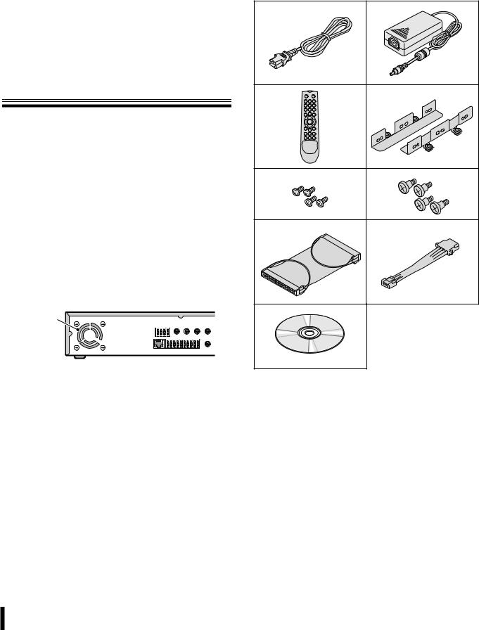
Check that all the parts shown below are supplied.
1 Power cable (×2) |
|
2 AC adapter |
3 Remote control |
4 HDD mounting bracket |
5 HDD bracket screw |
6 HDD fixing screw |
7 IDE cable |
8 HDD power cable |
9 CD-ROM |
• Instruction Manual (Digital Video Recorder)
1 |
2 |
3 |
4 |
5 |
6 |
7 |
8 |
9 |
|
1
Installing a hard disk
No default hard disk is installed at the time of purchase. To purchase and install a hard disk, consult the dealership where this unit was purchased.
Make sure the unit is turned off before installing the hard disk.
1Unfasten the cover of the unit.
Set the mode of the hard disk to be installed to "Master". For more information, read the hard disk installation manual.
2Fix the brackets to the hard disk using the supplied HDD mounting bracket screws (A).
A
A
3Connect the supplied IDE cable (B) and HDD power cable (C) to the hard disk and fix the hard disk to the unit using the supplied HDD fixing screws (D).
D
D
Black
B
Blue
 C
C
 Warning
The hard disk is a precision instrument. To avoid damage, handle the hard disk with care and do not expose it to shock.
Do not block the ventilation holes and do not allow the cooling fan to stop. Doing so may cause heat build up and may shorten the life expectancy of the hard disk.
GThis unit is designed to be positioned horizontally. Do not position vertically.
GDo not expose to shock or vibration and do not transport while power is turned on.
Always turn the power off when moving in and out of racks or other shelves.
GDo not remove the power plug while recording or playing images back.
GDo not move the unit for approximately 30 seconds after turning the power off.
The hard disk continues to rotate for a short duration after the power has been turned off. The unit is further susceptible to damage through shock and vibration during that period. It is imperative that you do not move the unit during that time.
GDo not expose to shock or vibration.
Avoid placing this unit directly on the floor. Make sure that the four stands attached to the base of this unit are used when placing it on the floor.
GAlways use the original packaging (packaging supplied at the time of purchase), when shipping the unit.
Make sure you use the packaging materials supplied at the time of the original purchase when shipping the unit or a single internal component of the unit. Select a shipping method that will cause the least amount of shock to the unit during shipping.
Consult the dealership where this unit was purchased for hard disk replacement.
•The hard disk is vulnerable to static electric shocks. Take appropriate measures to prevent exposure to static electricity.
•Unpackaged drives should be placed horizontally with their base plate facing upwards on top of a soft cloth. Exposing the hard disk to shocks and vibration may cause breakdowns.
•Do not expose the drive to shocks and/or vibrations when removing/tightening the screws at the time of hard disk replacement. Firmly tighten the screws after replacement.
2
Names and functions of parts
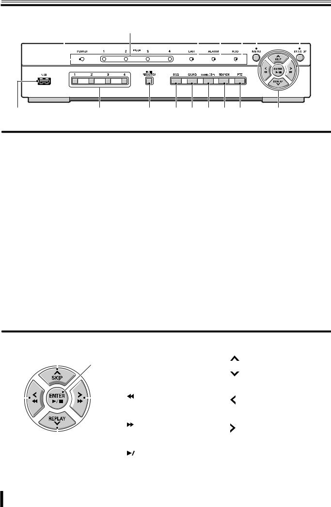
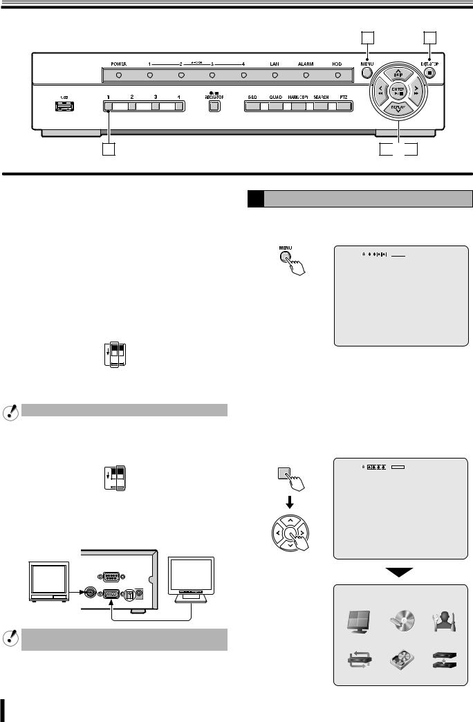
Front panel
1 |
2 |
3 |
4 |
5 |
6 |
7 |
||||||||||||||||
|
|
|
|
|
|
|
|
|
|
|
|
|
|
|
|
|
|
|
|
|
|
|
|
|
|
|
|
|
|
|
|
|
|
|
|
|
|
|
|
|
|
|
|
|
|
|
|
|
|
|
|
|
|
|
|
|
|
|
|
|
|
|
|
|
|
|
|
|
|
|
|
|
|
|
|
|
|
|
|
|
|
|
|
|
|
|
|
|
|
|
|
|
|
|
|
|
|
|
|
|
|
|
|
|
|
|
|
|
|
|
|
|
|
|
8 |
9 |
F |
G H I J K |
L |
There is no power switch on this unit.
1Power indicator (POWER)
The power indicator blinks when the supplied AC adapter is connected.
2Recording indicator (CH 1/CH 2/CH 3/CH 4)
The indicator blinks when a channel is recording.
3LAN indicator (LAN)
The indicator blinks when the unit is connected and used through the LAN cable.
4Alarm indicator (ALARM)
The indicator blinks when an alarm recording occurs.
5Hard disk drive indicator (HDD)
The indicator blinks when the hard disk is being accessed.
6Menu button (MENU) (P7/24)
Displays the settings menu screen and switches to setting mode.
7Exit/Stop button (EXIT/STOP) (P13)
During settings: Returns to the previous screen.
During playback: Interrupts playback operation.
8USB terminal (USB) (Exclusively for 2.0) (P21)
Connect the USB memory. Video can be saved.
9Camera selection 1 - 4 buttons (P7)
The video of each live is displayed on single-screen.
FRecord/Stop button (REC/STOP) (P12)
Starts/Stops the recording of the monitored live image displayed.
GAutomatic camera scrolling button (SEQ) (P10)
Automatically switches through and displays the images of each live.
HQuad-screen display button (QUAD) (P10)
Displays a quad-screen.
IMark/Copy button (MARK/COPY) (P21)
Switches to image saving mode.
JSearch button (SEARCH) (P18)
Switches to recorded-images searching mode.
KPan/Tilt/Zoom button (PTZ) (P11)
Switches the dome camera connected to the RS 422/485 terminal to Pan/Tilt/Zoom/Focus mode.
L Control button |
|
|
|
|
|
Playback in progress |
Setting in progress |
||||
|
|
|
|
|
|
|
|
|
|
(Cursor operation) |
|
|
|
A |
|
|
|
|
|
|
|||
|
|
|
A |
Skip button (SKIP): |
: |
||||||
|
|
|
|
E |
|
||||||
|
|
|
|
|
|
|
The player jumps one minute forward. |
Moves the cursor upward. |
|||
|
|
|
|
|
|
|
Replay button (REPLAY): |
: |
|||
|
|
|
|
|
|
B |
The player jumps one minute |
Moves the cursor downward. |
|||
|
|
|
|
|
|
|
backward. |
|
|||
|
|
|
|
|
|
|
|
|
|
|
|
C |
|
|
|
|
D |
|
|
button: |
: |
||
|
|
|
C |
The player fast rewinds. |
|||||||
|
|
|
|
|
|
Changes the settings value or moves |
|||||
|
|
|
|
|
|
|
|
|
|
|
|
|
|
|
|
|
|
|
|
|
|
|
the cursor to the left. |
|
|
|
|
|
|
|
|
|
|
|
|
|
|
|
|
|
|
|
|
button: |
: |
||
|
|
|
|
|
|
D |
The player fast-forwards. |
||||
|
|
|
|
|
|
Changes the settings value or moves |
|||||
|
|
|
|
|
|
|
|
|
|
|
|
|
|
B |
|
|
|
|
|
|
the cursor to the right. |
||
|
|
|
|
|
|
|
|
|
|
|
|
|
|
|
|
|
|
|
|
|
|
button: |
ENTER : |
|
|
|
|
|
|
|
|
|
|||
|
|
|
|
|
|
E |
The player displays a still image. |
Sets the selected item or displays the |
|||
|
|
|
|
|
|
Plays the image selected during the |
settings screen. |
||||
|
|
|
|
|
|
|
image search operation. |
|
|||
|
|
|
|
|
|
|
|
|
|
|
|
3
Names of each part and connections
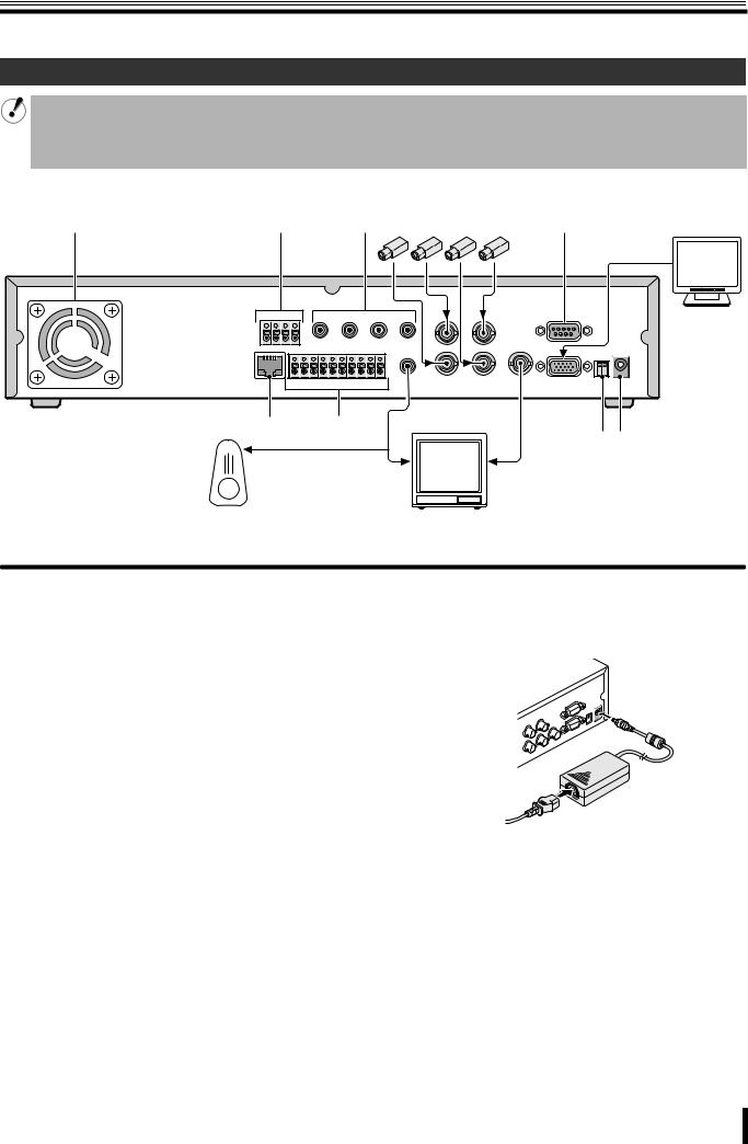
Rear panel
Basic connections
•Do not turn this unit on before all the connections are complete. Read the instruction manual of each unit carefully.
•Make sure each unit is connected properly as faulty connection may result in the unit emitting smoke and/or being damaged.
•Feed additional units with the same power source. Stored data may be lost.
•The DC plug of the AC adapter is very easily unplugged. When shifting this unit, remove the plug carefully.
Monitor Camera (Sold separately)
(Sold separately)
1 |
2 |
3 |
4 |
5 |
F |
|
|
|
|
|
6 |
7 |
8 |
9 |
|
|
|
|
G H |
|
|
|
|
|
|
To audio input terminal |
To video input terminal |
|||
Speaker with |
Video monitor |
|
built-in amplifier |
||
(Sold separately) |
||
(Sold separately) |
||
|
1 Cooling fan (P1)
2 PTZ camera control terminal (RS-422/485: P11)
3 Audio input (AUDIO IN: CH1 - CH4)
4 Video input terminal (VIDEO IN: CH1 - CH4)
5RS 232 terminal (RS-232C)
For maintenance purposes.
6 Network terminal (ETHERNET: P5)
7 External sensor terminal (SENSOR/ALARM OUT: P14)
8 Audio output terminal (AUDIO OUT)
9 Video output terminal (VIDEO OUT)
FVGA (Video Graphics Array) output terminal
Connects to the PC VGA monitor.
G System changeover switch (PAL/VGA: P7)
HDC12V input terminal (DC 12V)
Connect the power cable to the unit as shown in the illustration and insert the power plug into the outlet. The POWER indicator situated on the front panel blinks.
to AC 
4
Names of each part and connections
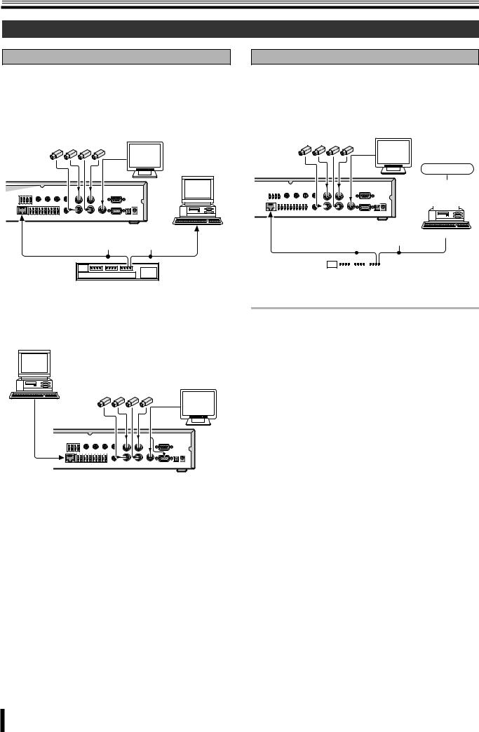
Network connection (ETHERNET)
LAN connection
bUsing the switching hub
Use a 10BASE-T/100BASE-TX CAT 5 LAN cable.
When controlling the network, connect to hubs such as the switching hub using an Ethernet cable.
Monitor Camera (Sold separately)
(Sold separately)
Computer
Ethernet cable (Straight cable)
Switching hub
bWithout using a switching hub
Computer
Monitor Camera (Sold separately)
(Sold separately)
Cross type
Internet (DHCP, ADSL) connection
Connect to the Internet using a router and the like.
When connecting to an ADSL modem or other device, read the instruction manual of the device for information on how to connect.
Monitor Camera (Sold separately)
(Sold separately)
Internet
|
|
|
|
|
|
|
|
Ethernet cable |
|
|
|
|
|
||||||||||||
|
|
|
|
|
|
|
|
|
|
|
|
|
|||||||||||||
|
|
|
|
|
|
|
|
|
|
|
|
|
|||||||||||||
|
|
|
|
|
|
|
|
|
|
|
|
|
|||||||||||||
|
|
|
|
|
|
|
|
|
|
|
|
|
|||||||||||||
|
|
|
|
|
|
|
|
|
|
|
|
|
|||||||||||||
|
|
|
|
|
|
|
|
Computer |
|||||||||||||||||
|
|
|
|
|
|
|
(Straight cable) |
|
|
|
|
|
|||||||||||||
|
|
|
|
|
|
|
|
|
|
|
|
|
|
|
|
|
|
|
|
|
|
|
|
|
|
|
|
|
|
|
|
|
|
|
|
|
|
|
|
|
|
|
|
|
|
|
|
|
|
|
|
|
|
|
|
|
|
|
|
|
|
|
|
|
|
|
|
|
|
|
|
|
|
|
|
|
|
|
|
|
|
|
|
|
|
|
|
|
|
|
|
|
|
|
|
|
|
|
|
|
|
|
|
|
|
|
|
|
|
|
|
|
|
|
|
|
|
|
|
|
|
|
|
|
|
|
|
|
|
|
|
|
|
|
|
|
|
|
|
|
|
|
|
|
|
|
|
|
|
|
|
|
|
|
|
Router or ADSL modem and the like
Memo: The type of network must be set on the NETWORK screen. (P33)
5
Pre-operation preparation
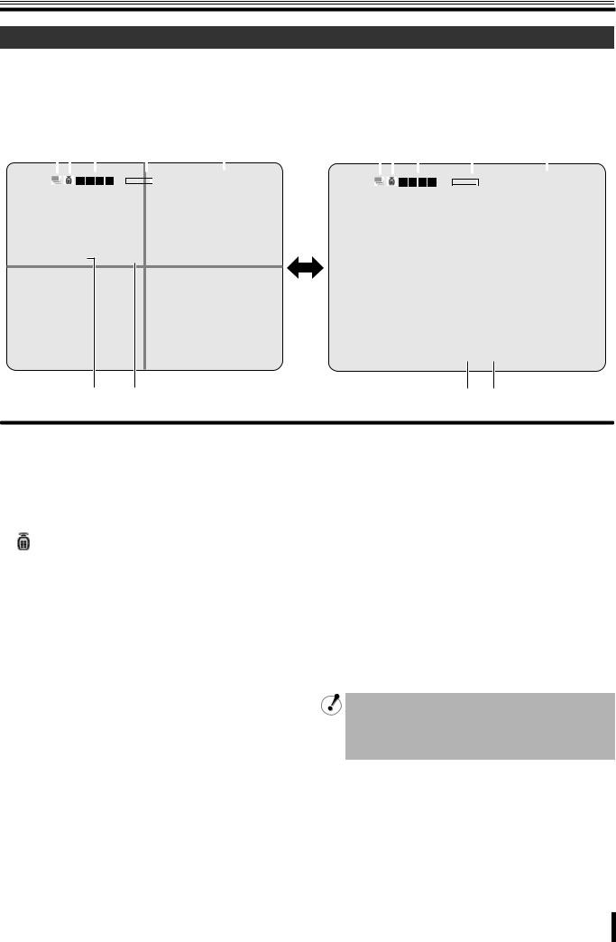
Screen display
After turning on the power, the message "INITIALIZING" is displayed. Next, the live videos are displayed on a quad-screen. The screen display necessary to operations is displayed on the screen.
• The screen display can be hidden except for the recording screen display. (P25)
b Quad-screen |
|
|
|
|
|
|
|
|
|
|
|
|
|
|
|
b Single-screen |
|
|
|
|
|
|
|
|
|
|
||||||||||||
|
12 |
|
|
|
3 |
|
|
|
4 |
|
|
|
5 |
|
|
12 |
3 |
|
|
|
4 |
|
|
|
5 |
|
|
|||||||||||
|
|
|
|
|
|
|
|
|
|
|
|
|
|
|
|
|
|
|
|
|
|
|
|
|
|
|
|
|
|
|
|
|
|
|
|
|
|
|
|
|
|
|
|
|
|
|
|
|
|
|
2% |
|
|
2006/07/14 |
09:04:54 |
|
|
|
|
|
|
|
|
|
|
|
|
2% |
|
|
2006/07/14 |
09:04:54 |
|
||||
CH1 |
C |
CH2 |
CH3 |
CH4 |
CH1 C |
6 7
1 Operation display
 : Displayed during live video sequencing.
 : Displayed during alarm output.
 : Displayed during remote operation by PC.
2 Remote control display (P32)
:This icon shows that remote operations are possible. Depending on the remote ID number settings, this icon may not be displayed and remote operations may not be available.
3 Alarm input display


 :
:
Blinks during motion or sensor alarm input. The mark is one channel from the left.
4Hard disk used capacity display
Displays the amount of recording on the hard disk from 0-99%. When the disk is full, "99%" changes to "FULL".
When the recording settings are set to overwrite and the
hard disk is full, 99% changes to  which represents overwriting mode.
6 7
5Date and time display
This unit manages the recorded videos according to their date and time. Make sure the correct date and time are set in the menu setting. (P7)
6Camera channel display
CH1/CH2/CH3/CH4
7Recording display
Factory default settings start continuous recordings (C) automatically once the power is turned on. Change the recording mode using the menu settings. (P27)
C: Recording in the continuous mode (CONTINUOUS)
R:Recording in the real time mode (When pressing the REC/STOP button)
M: Recording in the motion detection mode (BY EXT. MOTION)
S:Recording in the sensor detection mode (BY SENSOR)
•If a live video is disconnected, the message "VIDEO LOSS" is displayed on the monitor.
•If a video signal is not connected to the video input terminal, the message "NO VIDEO" is displayed on the monitor.
6
Pre-operation preparation
2
A |
Setting the television system and the monitor |
|
output |
If the television system of the camera to be connected and the type of monitor differ, live videos cannot be monitored on the normal screen. Check the specifications of the equipment to be connected and set the system changeover switch on the rear panel.
•Do not forget to turn off the power when adjusting the settings.
b Matching the television system of the camera (PAL)
P V
A G
L A
ON 1 2
Up: When using a NTSC camera
Down: When using a PAL camera
Cannot be used when PAL and NTSC system are mixed.
b Selecting the type of monitor (VGA)
P V
A G
L A
ON 1 2
Up: When connecting the general monitor to the video output terminal
Down: When connecting a PC monitor to the VGA terminal
The VGA terminal and the video output terminal cannot be used simultaneously.
1 8
3 
 7
7
B Setting the clock (CLOCK SET)
1Press the MENU button.
The PASSWORD input screen is displayed.


 2% 2006/07/14 08:06:09
PASSWORD
- - - -
CH1
•To return to the previous screen, press the EXIT/ STOP button.
2 Press the button 1 four times to enter "1111" and press the ENTER button.
The MAIN MENU screen is displayed.
• "1111" is the factory default setting password. We recommend you change the password to avoid unauthorized use. (P30)
1
 2% 2006/07/14 08:06:09
PASSWORD
* * * *
- - - -
CH1
MAIN MENU
LIVE |
|
RECORD |
SYSTEM |
NETWORK |
HDD SET |
SERVICE |
|
7

Pre-operation preparation
3Press the control button (~) twice and select the
SYSTEM, press the ENTER button.
The SYSTEM settings screen is displayed.
SYSTEM |
|
|
|
DVR ID |
DVR |
DESCRIPTION |
|
LOAD DEFAULT |
|
ADMIN PASSWORD |
|
NETWORK PASSWORD |
|
DATE FORMAT |
YYYY/MM/DD |
|
|
CLOCK SET |
|
PTZ CONTROL |
|
LANGUAGE |
ENGLISH |
REMOTE CONTROLLER ID |
0 |
D.S.T./SUMMER TIME |
OFF |
4Select DATE FORMAT using the control button ({|) and select the date display format using the control button (}~).
• YYYY/MM/DD |
• YYYY-MM-DD |
||
|
(Example: 2006/12/15) |
|
(Example: 2006-12-15) |
• |
MM/DD/YYYY |
• |
MM-DD-YYYY |
• |
DD/MM/YYYY |
• |
DD-MM-YYYY |
5Select CLOCK SET using the control button ({|) and press the ENTER button.
The CLOCK SET screen is displayed.
6Select the date/time to be changed using the control button (}~), select a value using the control button ({|), repeat to set the date/time and press the ENTER button.
The UPDATE DATE&TIME screen is displayed.
CLOCK SET
2006/12/15 10:20:30
UPDATE DATE&TIME
CANCEL |
CONFIRM |
The time on this CLOCK SET screen has not been calculated considering summer time.
7Select CONFIRM using the control button (}~) and press the ENTER button.
The screen switches to the "INITIALIZING..." screen. The live videos as well as the set date/time are displayed on the monitor.
b In the event that the clock is early
Reset the clock using the CLOCK SET, select "CONFIRM" under "UPDATE DATE&TIME". The TIME MISMATCH screen is displayed, select "YES".
•YES:
The videos between "SYSTEM TIME" and "HDD LAST TIME" are lost.
•GO TEST MODE:
Do not select. (Maintenance mode)
UPDATE DATE&TIME
CANCEL |
CONFIRM |
|
INITIALIZING... |
|
|
CH1 |
C |
CH2 |
C |
CH3 |
C |
CH4 |
C |
TIME MISMATCH. |
||
WILL YOU ERASE INDEX? |
|
|
IF YES, SOME DATA WILL BE ERASED FROM HDD. |
||
CH1 |
R |
CH2 |
IF THE DATA IS TO BE KEPT, SELECT GO TEST MODE. |
||
SYSTEM TIME: |
2006-09-09 |
19:56:36 |
HDD LAST TIME: 2006-09-09 |
20:05:45 |
|
GO TEST MODE |
YES |
CH3 |
CH4 |
8

Pre-operation preparation
C Setting the language (LANGUAGE)
1 Follow steps 1 to 3 of the CLOCK SET procedure
2Select LANGUAGE using the control button ({|) and select the display language using the control button (}~).
Once a language has been selected the display language changes.
SYSTEM |
|
DVR ID |
DVR |
DESCRIPTION |
|
LOAD DEFAULT |
|
ADMIN PASSWORD |
|
NETWORK PASSWORD |
|
DATE FORMAT |
YYYY/MM/DD |
CLOCK SET |
|
PTZ CONTROL |
|
LANGUAGE |
ENGLISH |
REMOTE CONTROLLER ID |
0 |
D.S.T./SUMMER TIME |
OFF |
Language selection:
ENGLISH, , DEUTSCH, Français, ESPAÑOL, ITALIANO, ipllXTT ìRàX, , POLSKI, CESKY, óçhHBjlXT LRTX, Româna, Srpski, SVENSKA
DSetting the summer time (D.S.T./SUMMER TIME)
Summer time setting is available.
1Select D.S.T./SUMMER TIME using the control button ({|) and select "ON" using the control button (}~).
It becomes possible to input summer time.
|
|
|
SYSTEM |
|
|
|
|
DVR ID |
DVR |
||||||
DESCRIPTION |
|
|
|
|
|||
LOAD DEFAULT |
|
|
|
|
|||
ADMIN PASSWORD |
|
|
|
|
|||
NETWORK PASSWORD |
|
|
|
|
|||
DATE FORMAT |
YYYY/MM/DD |
||||||
CLOCK SET |
|
|
|
|
|||
PTZ CONTROL |
|
|
|
|
|||
LANGUAGE |
ENGLISH |
||||||
REMOTE CONTROLLER ID |
0 |
|
|
|
|||
D.S.T./SUMMER TIME |
ON |
||||||
|
|
|
BEGIN |
2/1 0H |
|
|
|
|
|
|
END |
8/1 0H |
|
|
|
|
|
|
|
|
|
|
|
Initial value
2Select "BEGIN" using the control button ({|) and press the ENTER button.
D.S.T./SUMMER TIME BEGIN is displayed.
3 Input the starting date (31 March, 23:00).
1 Display "0" using the control button ({|) and move to the right using the control button (}~).
2 Display "3" using the control button ({|) and move to the right using the control button (}~), repeat to set other settings and press the ENTER button.
The summer time input selection screen is displayed again.
D.S.T./SUMMER TIME BEGIN
0 3 / 3 1 2 3 H
4Repeat the procedure to input the end date (31 August, 23:00).
D.S.T./SUMMER TIME END
0 8 / 3 1 2 3 H
9

Monitoring the camera videos
A |
C B |
A Single-screen display
Example: Displaying camera 2 on single-screen
1Press "2" on the camera selection button.
The video of camera 2 is displayed on single-screen.
2
 2% 2006/07/14 08:06:09
CH2 C
B Quad-screen display
Displays the 4 cameras video connected at once.
1Press the QUAD button.
The quad-screen is displayed.
|
2% |
2006/07/14 |
09:04:54 |
CH1 |
C |
CH2 |
C |
CH3 |
C |
CH4 |
C |
2To return to single-screen press any of the camera selection buttons.
1 4
C Camera sequencing
Switches the cameras video in sequence.
1Press the SEQ button while in single-screen display.
The cameras automatically switch in sequence starting with the channel of the camera being displayed. If there is an audio input, the audio also switches in channel sequence order.
Sequence display
 2% 2006/07/14 09:04:54
CH2 C
 1
1
2
3
4
Memo: The sequence interval from one camera video to another can be set. (P25)
2Press the SEQ button once operations are complete.
The sequence mode is cancelled.
10
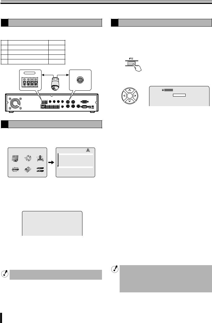
Operating the PTZ camera
If a PTZ camera is connected to the RS422/485 terminal, Pan/Tilt, Zoom/Focus operations are available from this unit.
1 Connection
Connect the RS422/485 terminal and the camera using a twisted pair cable.
|
RS422 |
|
RS485 |
||
1 |
TX+ (+Transmit Data) |
A |
|||
2 |
TX- (-Transmit Data) |
B |
|||
3 |
RX+ (+Receive Data) |
– |
|||
4 |
RX- (-Receive Data) |
– |
|||
|
|
RS-422/485 |
|
|
|
|
TX+ TXRX+ RX- |
|
|||
|
1 |
2 |
3 |
4 |
|
3 Operation
1Select the number of the dome camera connected using the camera selection button.
2Press the PTZ button.
The control screen is displayed.
3 Controlling the camera
 2% 2006/07/14 17:25:37
PAN/TILT
ZOOM/FOCUS
INITIALIZE
2 Settings
1Press the MENU button (the MAIN MENU is displayed) and select SYSTEM using the control button (}~).
|
MAIN MENU |
|
|
SYSTEM |
|
|
|
|
|
|
|
|
|
|
|
DVR ID |
DVR |
|
|
|
|
DESCRIPTION |
|
|
|
|
|
LOAD DEFAULT |
|
|
|
|
|
ADMIN PASSWORD |
|
|
|
|
|
NETWORK PASSWORD |
|
LIVE |
RECORD |
SYSTEM |
|
DATE FORMAT |
YYYY/MM/DD |
|
|
|
|
CKLOCK SET |
|
|
|
|
|
PTZ CONTROL |
|
|
|
|
|
LANGUAGE |
ENGLISH |
|
|
|
|
REMOTE CONTROLLER ID |
0 |
NETWORK |
HDD SET |
SERVICE |
D.S.T./SUMMER TIME |
OFF |
|
|
|
||||
•A password is requested when pressing the MENU button. (P7)
2Place the cursor on PTZ CONTROL and press the ENTER button.
The PTZ CONTROL screen is displayed.
|
PTZ CONTROL |
|
|
DATA SPEED |
19200 14400 9600 4800 2400 |
CHANNEL |
1 2 3 4 |
PROTOCOL |
- - - - |
ADDRESS |
0 |
3Place the cursor on the settings item and setting. DATA SPEED: Selecting the communication speed
CHANNEL: Selecting a connected channel
PROTOCOL: Selecting the type of protocol
ADDRESS: Selecting the camera ID (0-63)
When several cameras are connected, select the same protocol for all cameras.
4Press the EXIT/STOP button once the settings are complete.
b Pan/Tilt operations
1Select "PAN/TILT" using the control button ({|) and press the ENTER button.
2 Adjust the tilt position using the control button ({|) and adjust the pan position using the control button (}~).
•The following message is displayed on the screen during operations.
Up/Down key: Tilt Up/Down
Left/Right key: Pan Left/Right
b Zoom/Focus operations
1Select "ZOOM/FOCUS" using the control button ({|) and press the ENTER button.
2Adjust the zoom using the control button ({|) and adjust the focus position using the control button (}~).
•The following message is displayed on the screen during operations.
Up/Down key: Zoom In/Out
Left/Right key: Focus Near/Far
b Initializing the camera position
Select "INITIALIZE" using the control button ({|) and press the ENTER button.
•Once the initialization is complete, the following message is displayed on the screen and the adjustment position is reset to its default values. "INITIALIZE SUCCESS!"
4Press the EXIT/STOP button once operation are complete.
•If a PTZ camera is not connected to this unit, the following message is displayed on the screen. "Please set up a camera type in setup menu."
•The terminator settings of this unit are set to "ON". Consult the dealership where this unit was purchased for any changes.
11
 Loading...