


DSR-3716P
See “INSTRUCTION MANUAL” for menu settings
or details of the operation.
Contents
1 NAMES AND FUNCTIONS OF PARTS .......... 1
Front panel ..................................................... 1
INTRODUCTION
1 PREPARING FOR USE................................... 4
Operation display area..................................... 4
Changing the position of the operation
display area...................................................... 5
Changing the language.................................... 5
Setting the time................................................ 6
2 VIEWING VIDEO FROM A CAMERA ............. 7
Viewing on a full screen ................................... 7
Viewing on quad screens................................. 7
Viewing on multi screens
(9 screens/ 16 screens) ................................... 8
Viewing on plus screen .................................... 8
3 RECORDING ................................................... 9
Normal recording ............................................. 9
Timer recording................................................ 9
Alarm recording.............................................. 10
Normal recording easy setup......................... 11
4 PLAYBACK ................................................... 12
OPERATION
Playing video on a full screen ........................ 12
Fast-forward and fast-rewind playback .......... 12
Performing frame advance
(forward or reverse) ....................................... 13
5 SEARCHING FOR RECORDED VIDEO ....... 14
Alarm search.................................................. 14
Alarm thumbnail search ................................. 15
Time/date search ........................................... 16
6 SAVING (COPYING) RECORDED VIDEO ... 17
Copying video to a CompactFlash card
or Microdrive .................................................. 17
Printing images from CompactFlash cards
(quick print) .................................................... 19
Copying video to CD-R/RW ........................... 20

1 NAMES AND FUNCTIONS OF PARTS
DSR-3716P
FUNC.
MULTI
AUTO PAN
PLUSMON 2
TOUR
9
12 13 14
MENU
MENU
ZOOM
SEQUENCE
REC/STOP
1615 17
EXIT/OSD
ENTER AF
SEARCH
COPY
SHUTTLE HOLD
TIMER
PLAY/STOP
STILL
IRIS
FOCUS
ALARM
ZOOM/I/FO
27
28
29
1
POWER FULL ALARM FULL LOCK ALARM
2345
AUDIO
OUT
VIDEO
USB
45
12 13
678123
14 15
8 7
QUAD
1691011
PRESET
SEQUENCE
24
SHUTTLE
JOG
E
N
T
R
A
E
L
C
E
R
CARD
MENU
MENU
RESET
PAN
EJECT
25
26
6
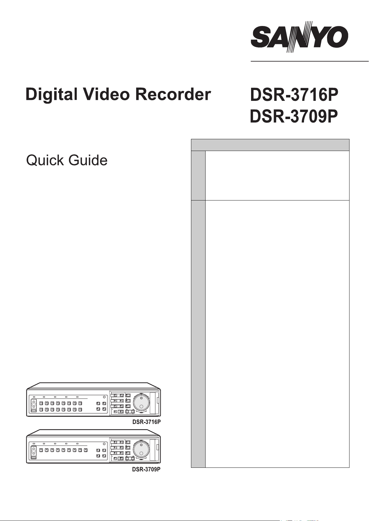
Front panel
1. POWER indicator
The POWER indicator will light up when the power is
turned on.
If the internal HDD or fan begins to malfunction, this
indicator will be flashed.
2. FULL indicator
The FULL indicator will begin to flash when the amount of
available memory in the hard disk’s normal recording area
drops to the percentage specified using menu settings.
In addition, recording will stop automatically when no more
memory is available, and the FULL indicator will switch to
a permanently lit condition.
This indicator can then be turned off by performing “AREA
FULL RESET” using menu settings.
3. ALARM FULL indicator
The ALARM FULL indicator will begin to flash when the
amount of available memory in the hard disk’s alarm
recording area drops to the percentage specified using
menu settings.
In addition, recording will stop automatically when no more
memory is available, and the ALARM FULL indicator will
switch to a permanently lit condition.
This indicator can then be turned off by performing “AREA
FULL RESET” using menu settings.
4. LOCK indicator
The LOCK indicator lights up when operation has been
locked using <SECURITY LOCK SET>.
An alarm will be sounded if a button is pressed in this
condition. In addition, a password entry screen will be
displayed on the monitor at this time.
If the correct administrator password is entered, the lock
condition will be cancelled and the LOCK indicator will turn
off.
5. ALARM indicator
The ALARM indicator flashes during alarm recording, and
it is lit up during pre-alarm recording.
10 11
18
22 23 20
21
19
6. [CAMERA SELECT] buttons and indicators
When one or more cameras have been connected to the
VIDEO IN terminals on the digital video recorder’s rear
panel and the appropriate [CAMERA SELECT] button is
pressed, the corresponding indicator lights up and the
video feed from that camera is displayed on-screen.
z During quad, multi 9 or 16 screen display:
The indicators corresponding to the cameras being
displayed on the monitor are lit up.
z If video is lost:
The indicator starts to flash.
z If an alarm occurs:
The indicator for the corresponding camera starts to flash.
7. [FUNC.] button and indicator
Switch to normal mode or camera control mode.
Press button for camera control mode and indicator will
light. Press button again to return to normal mode.
Indicator turns off.
8. [QUAD] button and indicator
The [QUAD] button is used to display video in quad
screens, and the indicator will light up when this type of
display is being presented.
The QUAD indicator will turn off when a different screen
display mode is adopted.
9. [MULTI] button and indicator
The [MULTI] button is used to display video in multi 9 or 16
screens, and the indicator will light up when this type of
display is being presented.
The MULTI indicator will turn off when a different screen
display mode is adopted.
The DSR-3709P can only display video in nine screens.
10. [MON2] button and indicator
If the [MON2] button is pressed while a monitor is
connected to the MON2 output terminal on the rear panel,
it will be possible to change the monitor 2 output video.
The [CAMERA SELECT] and [SEQUENCE] buttons can
be used, and the indicator will be lit up during the setting
procedure.
English 1
NAMES AND FUNCTIONS OF PARTS1
DSR-3709P
1
POWER FULL ALARM FULL LOCK ALARM
27
28
29
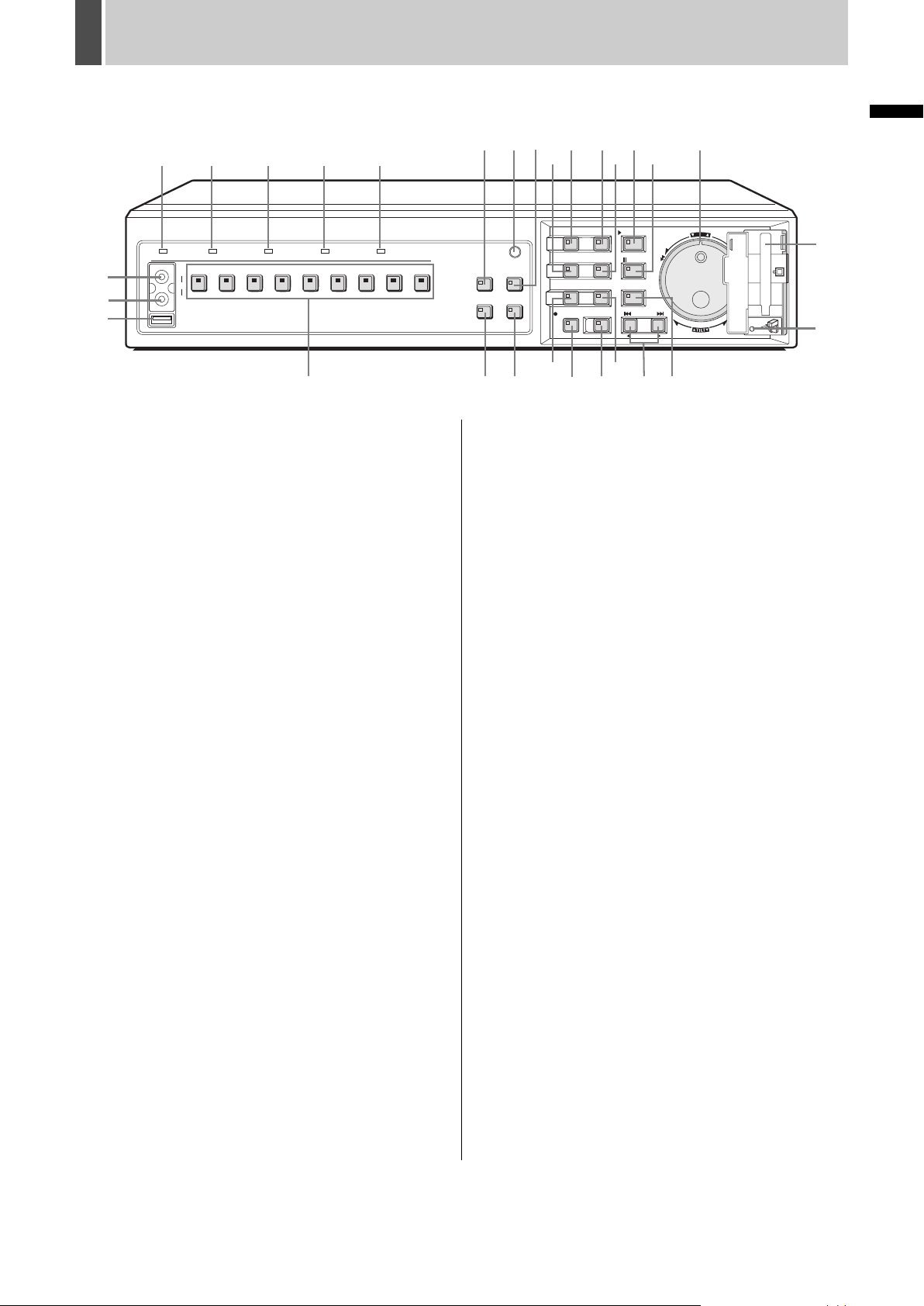
11. [PLUS] button and indicator
The [PLUS] button is used to enlarge video from a single
camera to quad screen size during multi 9 or multi 16
screen display.
For DSR-3709P, this operation is available only when in
multi 9 screen display.
12. [MENU] button and indicator
The [MENU] button is used to display the menu screens
(i.e., setting screens), and the indicator lights up while any
of these screens is being displayed.
13. [EXIT/OSD] button and indicator
z EXIT
The [EXIT/OSD] button is used to exit the main menu or a
sub-menu. When a menu is displayed, the indicator turns
off; when the menu is closed and the normal display is
restored, the indicator lights up.
z OSD
Each time the [EXIT/OSD] button is pressed while the
digital video recorder is recording, playing, or stopped, the
operating display location moves in the order of top of
screen, bottom of screen, to hidden; furthermore, the
indicator lights up when this information is being displayed.
14. [PLAY/STOP] button and indicator
When the [PLAY/STOP] button is pressed, a recording
from the normal recording area or alarm recording area is
played and the indicator lights up. When pressed during
playback, this button stops the digital video recorder.
15. [ZOOM] button and indicator
When the [ZOOM] button is pressed during monitoring or
playback on a full screen, a portion of the playback video is
magnified and the indicator flashes.
2345
AUDIO
OUT
VIDEO
USB
45
6 7 8 9123
6
8 7
12 13 14
9
24
1615 17
SHUTTLE
JOG
E
N
T
R
A
E
L
C
E
R
CARDCARD
CARD
MENU
MENU
RESET
RESET
EJECT
PAN
EJECT
QUAD
PRESET
SEQUENCE
10 11
FUNC.
MULTI
AUTO PAN
PLUSMON 2
TOUR
MENU
EXIT/OSD
PLAY/STOP
MENU
ENTER AF
ZOOM
SEARCH
STILL
COPY
TIMER
IRIS
SHUTTLE HOLD
FOCUS
19
SEQUENCE
REC/STOP
18
21 22 23 20
ALARM
ZOOM/I/FO
17. [STILL] button and indicator
When the [STILL] button is pressed during playback, the
current frame is displayed as a still image and the indicator
lights up. Playback can be resumed by pressing this button
once again.
18. [SEQUENCE] button and indicator
The [SEQUENCE] button can be pressed during
monitoring to automatically switch between screen display.
When pressed, the indicator begins flashing and the
display is changed automatically. The lighting condition of
CAMERA SELECT indicators also changes in response to
the screen display.
19. [COPY] button and indicator
The [COPY] button is used to copy recorded video to the
hard disk’s archive area, to a CompactFlash card, CD-R/
RW or to a Microdrive.
The indicator lights up during the copy process.
20. [SHUTTLE HOLD] button and indicator
The [SHUTTLE HOLD] button is used to lock shuttle dial
operation for a constant speed of playback or slow playback.
The indicator lights up while the shuttle dial is locked.
When a password has been set, furthermore, this button
can be pressed for at least three seconds to activate the
security lock.
21. [REC/STOP] button and indicator
The [REC/STOP] button is pressed to start normal
recording, and the indicator lights up during this process.
Furthermore, pressing this button for at least three
seconds stops recording and turns off the indicator.
INTRODUCTION
25
26
16. [SEARCH] button and indicator
When the [SEARCH] button is pressed while the digital
video recorder is recording or stopped, the search menu is
displayed and the indicator lights up. The search menu
can be closed by pressing this button once again.
2 English
NAMES AND FUNCTIONS OF PARTS1
DSR-3716P
1
POWER FULL ALARM FULL LOCK ALARM
27
28
29
2345
AUDIO
OUT
VIDEO
USB
45
12 13
678123
14 15
8 7
9
12 13 14
24
1615 17
MENU
EXIT/OSD
PLAY/STOP
MENU
ENTER AF
ZOOM
SEARCH
COPY
TIMER
STILL
IRIS
SHUTTLE HOLD
FOCUS
ALARM
ZOOM/I/FO
FUNC.
QUAD
MULTI
AUTO PAN
PRESET
SEQUENCE
PLUSMON 2
TOUR
1691011
SEQUENCE
REC/STOP
SHUTTLE
JOG
E
N
T
R
A
E
L
C
E
R
CARD
MENU
MENU
RESET
PAN
EJECT
25
26
6
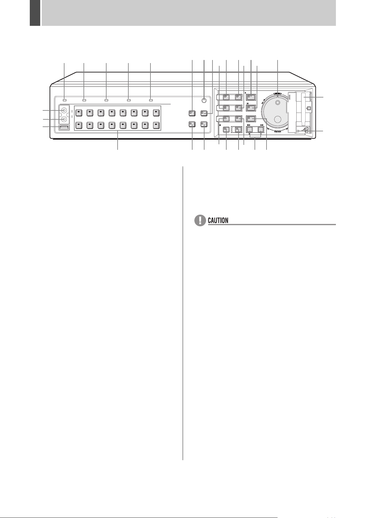
22. [TIMER] button and indicator
If the [TIMER] button is pressed while the recording is
stopped, timer recording standby mode is adopted and
recording will then start automatically at the set time. The
indicator will be lit up while in timer recording standby
mode or timer recording.
If the button is pressed during timer recording, this process
is stopped and the indicator turns off. Furthermore, if the
[TIMER] button is pressed when in timer recording standby
mode, indicator is turned off and timer recording is
cancelled.
23. [ALARM] buttons
When an [ALARM] button is pressed during playback or
still, the digital video recorder skips to the next earlier or
next later alarm.
24. Jog dial (inside) and shuttle dial (outside)
z During playback:
Use the jog dial to change the playback speed.
Use the shuttle dial to perform fast-forward or fastreverse playback.
z During menu display:
Use the jog dial to move the cursor and to change
setting values. Use the shuttle dial to confirm settings.
10 11
18
22 23 20
21
19
28. Video output terminal
This terminal outputs the same video as that of the MAIN
MONITOR output terminal on the rear panel.
29. USB terminal
This terminal connects to a recordable CD-R/RW drive.
z The USB terminal is for the use of the recommended
Sanyo CD-R/RW drive (sold separately). Nonrecommended peripherals cannot be connected.
z For recommended recordable drives, check the Sanyo
homepage or ask at your local Sanyo dealer.
Sanyo website URL:
http://www.sanyosecurity.com
25. CompactFlash card slot
This slot is used to house a CompactFlash card or Microdrive.
26. [MENU RESET] button
The [MENU RESET] button is used to default menu
settings.
When setting motion sensors, furthermore, all sensors on
the same line as the cursor can be turned on
simultaneously by pressing this button.
27. Audio output terminal
Audio output is the same as that of the rear panel AUDIO
OUT terminal.
English 3
1 PREPARING FOR USE
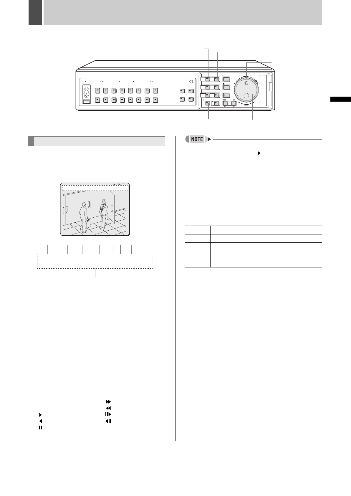
[MENU] button [EXIT/OSD] button
Shuttle dial
CARDCARD
MENU
RESET
EJECT
OPERATION
Operation display area
Whenever the power is turned on, the operation display
area will be shown at the top of the monitor screen. This
area indicates the date, time, picture quality, and other
information needed for operation.
01-01-04 00:00:00 REC REPEAT EN A ALARM 0000
02
(1) (2) (3) (4) (5)(6) (7)
01-01-04 00:00:00 REC REPEAT EN A ALARM 0000
02
(8)
(1) Date display
“01-01-04” (day-month-year) is displayed when you
turn the power on for the first time. Be sure to specify
the correct date using menu settings.
(2) Time display
“00:00:00” is displayed when you turn the power on for
the first time. The digital video recorder uses the date
and time to manage recording and playback points.
Accordingly, if the time has not been set correctly, you
will not be able to effectively search for video data.
Make sure to specify the time using menu settings.
Recording will not be possible until a setting has been
made.
(3) Operating symbol display
Displays the current operation (such as recording or
playback).
REC: Recording : Fast-forward playback
EXT: External timer recording : Fast-rewind playback
: Playback : Slow playback
: Reverse playback : Reverse slow playback
: Still
0
[REC/STOP] button
Jog dial
z During simultaneous recording and playback, the
display indicates playback ( ).
(4) Remaining memory in recording area
Displays the remaining area memory as a percentage
when overwriting in the normal recording area or the
alarm recording area is forbidden. If overwriting has
been permitted, “REPEAT” is displayed.
(5) Picture quality display
Displays the quality of the video that can be recorded
on the hard disk. Set to “EN” (Enhanced) by default.
BA Basic
NO Normal
EN Enhanced
FI Fine
SF Super Fine
(6) Audio recording display
“A” is displayed when audio is being recorded or
played back.
(7) Alarm display and alarm count display
When you set an alarm using the “ALARM REC
MODE SET” menu item, the alarm display area
presents the following information.
z When alarm recording is set;
“ALARM” is displayed.
“ALARM” is flashed during alarm recording.
z When pre-alarm recording is set;
“PRE” is displayed.
When an alarm occurs, “PRE” disappears,
“ALARM” is displayed, and the number of alarms is
shown. The total number is indicated in the alarm
display.
z When performing playback from the archive
area;
“ARCHIV” is displayed.
z When an external alarm signal is activated;
“EA” is flashed to the left of the camera number.
4 English
PREPARING FOR USE1
z When a motion sensor alarm signal is
activated;
“SA” is flashed to the left of the camera number.
z When an external alarm signal and motion
sensor signal are activated;
“ES” flashes to the left of the camera number.
(8) Camera title display
The camera number or camera title is displayed. In
addition, when an alarm occurs, the camera number
and alarm “EA”, “SA” or “ES” are displayed along with
the camera title.
z During video loss;
The display alternates between showing the
camera title and “VIDEO LOSS”. “VIDEO LOSS”
flashes when the operating display is hidden.
z During no video signal;
“NO VIDEO” is displayed in place of the camera
title.
z Although operations such as playback, copying, and
data transfer are possible while recording, this unit
gives priority to recording, and other operations may be
delayed as a result.
Changing the language
Use the following procedure to set the language displayed
on the monitor.
[Settings] ( indicates default setting)
Item Setting Description
ENGLISH Sets the language to English.
LANGUAGE
FRANCAIS Sets the language to French.
DEUTSCH Sets the language to German.
ESPAÑOL Sets the language to Spanish.
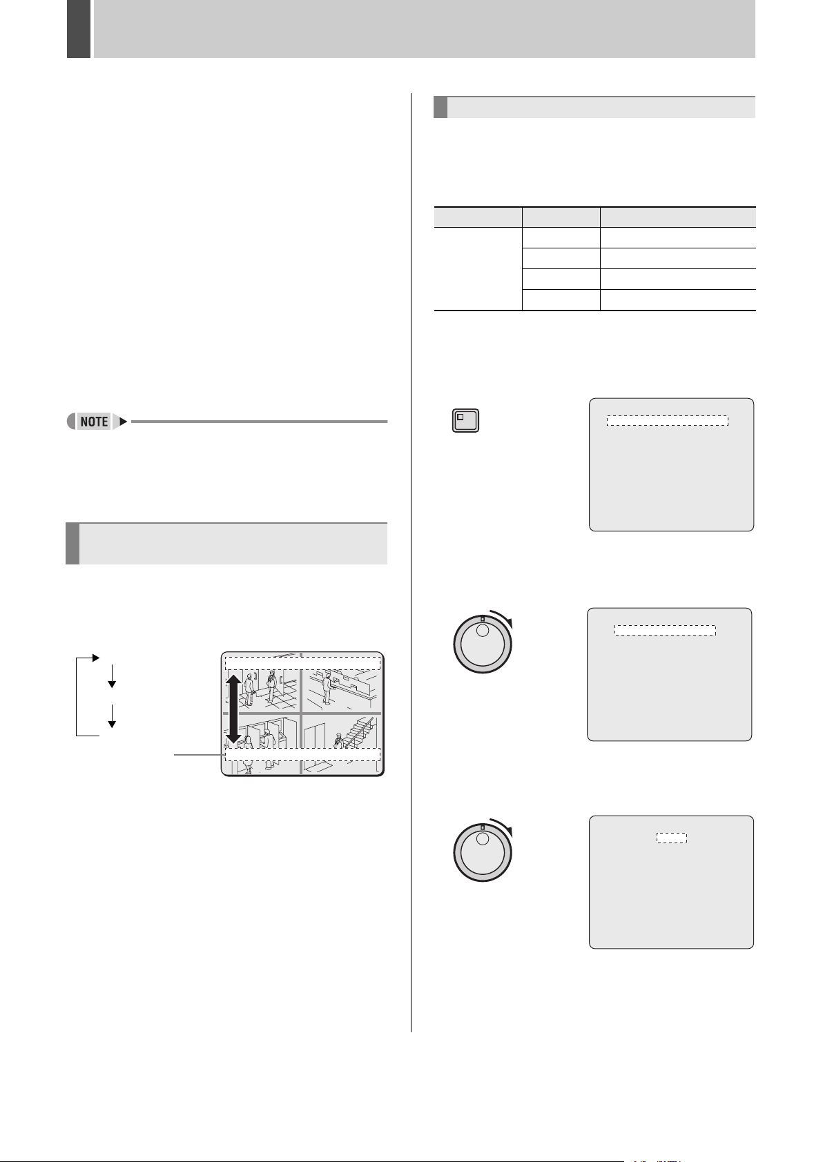
1 Press the [MENU] button.
The MENU indicator lights up and the <MAIN MENU> is
displayed.
MENU
<MAIN MENU>
1.INITIAL SET ->
2.RECORD SET ->
3.GENERAL SET ->
4.SCREEN SET ->
5.POWER LOSS/USED TIME ->
6.INITIALIZATION LOG ->
7.COPY MENU SETTINGS ->
Changing the position of the
operation display area
1 Press the [EXIT/OSD] button.
As the [EXIT/OSD] button is pressed, the operation display
area moves to a different location or is hidden.
Top (default)
Bottom
Hidden
Operation
display area
01-01-04 00:00:00 REC REPEAT EN A ALARM 0000
01 02
01-01-04 00:00:00 REC REPEAT EN A ALARM 0000
03 04
MOVE:JOG SELECT:SHUTTLE
2 Turn the shuttle dial clockwise.
The <INITIAL SET> screen is displayed.
<INITIAL SET>
1.LANGUAGE/CLOCK SET ->
2.CAMERA DETECT ->
3.TITLE SET ->
4.HOLIDAY SET ->
5.TIME PERIOD SET ->
MOVE:JOG SELECT:SHUTTLE
3 Turn the shuttle dial clockwise.
The cursor moves to “ENGLISH”.
<LANGUAGE/LANGUE/SPRACHE/IDIOMA>
ENGLISH
<CLOCK SET>
01-01-2004 THU 00:00:00
<SUMMER TIME SET>
MODE : USE
WEEK MONTH TIME
ON LST-SUN 03 02:00
OFF LST-SUN 10 02:00
<EXT.CLOCK SET>
ADJUST. TIME 01:00
English 5
PREPARING FOR USE1
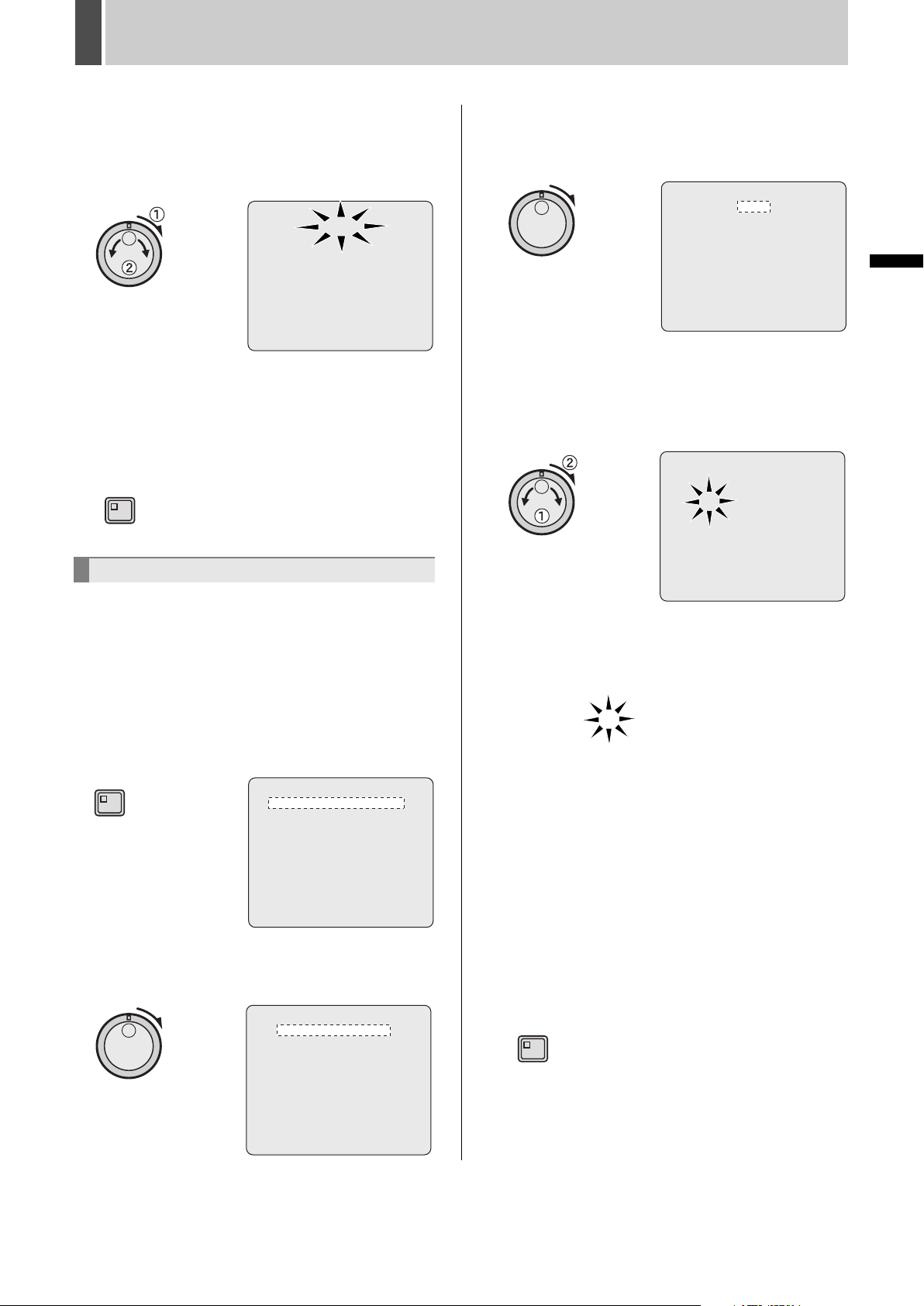
4 Turn the shuttle dial clockwise, and
then turn the jog dial to select the
desired language.
The set item flashes.
<REGL.LANGUE>
FRANCAIS
<REGL.HORLOGE>
01-01-2004 JEU 00:00:00
<HEURE D
MODE : MARCHE
SEMAINE MOIS HEURE
ON DER-DIM 03 02:00
OFF DER-DIM 10 02:00
<REGL.HORLOGE EXTERNE>
REGL.DE L
,
ETE>
,
HEURE 01:00
5 When you have made a selection, turn
the shuttle dial clockwise.
The cursor moves to the date and time.
The language has now been set.
To return to the normal screen, press the [EXIT/OSD] button.
EXIT/OSD
Setting the time
(Default: 01-01-2004 THU 00:00:00)
Be sure to set the correct date and time as these settings
are used during recording and searching.
Example: Setting 8:30 on 26 October 2004
3 Turn the shuttle dial clockwise.
The <LANGUAGE/LANGUE/SPRACHE/IDIOMA> screen
is displayed.
<LANGUAGE/LANGUE/SPRACHE/IDIOMA>
ENGLISH
<CLOCK SET>
01-01-2004 THU 00:00:00
<SUMMER TIME SET>
MODE : USE
WEEK MONTH TIME
ON LST-SUN 03 02:00
OFF LST-SUN 10 02:00
<EXT.CLOCK SET>
ADJUST. TIME 01:00
4 Turn the jog dial to select the date and
time for <CLOCK SET> and turn the
shuttle dial clockwise.
“01” flashes (indicating the day).
<LANGUAGE/LANGUE/SPRACHE/IDIOMA> K
ENGLISH
<CLOCK SET>
01-01-2004 THU 00:00:00
<SUMMER TIME SET>
MODE : USE
WEEK MONTH TIME
ON LST-SUN 03 02:00
OFF LST-SUN 10 02:00
<EXT.CLOCK SET>
ADJUST. TIME 01:00
5 Set “26” with the jog dial or numeric
keys and turn the shuttle dial clockwise.
“01” flashes (indicating the month).
OPERATION
1 Press the [MENU] button.
The MENU indicator lights up and the <MAIN MENU> is
displayed.
MENU
<MAIN MENU>
1.INITIAL SET ->
2.RECORD SET ->
3.GENERAL SET ->
4.SCREEN SET ->
5.POWER LOSS/USED TIME ->
6.INITIALIZATION LOG ->
7.COPY MENU SETTINGS ->
MOVE:JOG SELECT:SHUTTLE
2 Turn the shuttle dial clockwise.
The <INITIAL SET> screen is displayed.
<INITIAL SET>
1.LANGUAGE/CLOCK SET ->
2.CAMERA DETECT ->
3.TITLE SET ->
4.HOLIDAY SET ->
5.TIME PERIOD SET ->
MOVE:JOG SELECT:SHUTTLE
26-01-2004 MON 00:00:00
6 Use the same procedure to set the
month (10), year (2004), hour (08), and
minute (30).
When you have set the minute, the cursor moves to
“MODE” under <SUMMER TIME SET>, and the clock
starts counting from 00 seconds.
z The week day is set automatically.
z The clock is stopped during date and time settings.
7 Press the [EXIT/OSD] button.
The setting procedure is ended and the display returns to
the normal screen.
EXIT/OSD
6 English
 Loading...