


SERVICE MANUAL Microwave Oven |
EM-C1900 (U.K) |
Pro.Code No. |
Model No. |
437 623 00 |
EM-C1900UK |
|
|
Foreword
Read this manual carefully, especially precaution on microwave energy, and follow the procedure strictly,careless servicing and testing may expose yourself to the microwave energy leakage.
PRECAUTIONS
PRECAUTIONS TO BE OBSERVED BEFORE AND DURING SERVICING TO AVOID POSSIBLE EXPOSURE
TO EXCESSIVE MICROWAVE ENERGY
(a)Do not operate or allow the oven to be operated with the door open.
(b)Make the following safety checks on all ovens to be serviced before activating the magnetron or other microwave source, and make repairs as necessary:
(1)Interlock operation, (2) proper door closing, (3) seal and sealing surfaces (arcing, wear, and other damage),
(4) damage to or loosening of hinges and latches, (5) evidence of dropping or abuse.
(c)Before turning on microwave power for any service test or inspection within the microwave generating compartments, check the magnetron, wave guide or transmission line, and cavity for proper alignment, integrity, and connections.
(d)Any defective or misadjusted components in the interlock, monitor, door seal, and microwave generation and transmission systems shall be repaired replaced, or adjusted by procedures described in this manual before the oven is released to the owner.
REFERENCE NO. SM-6310022-00

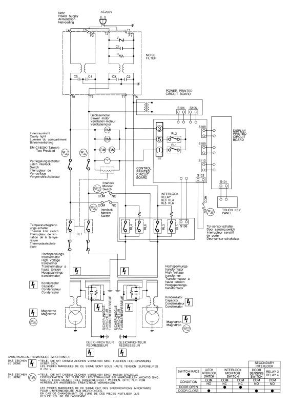
5.CIRCUIT DIAGRAM
Figure 2
*Caution :The voltage between filament leads of magnetron is about 3.3VA.C, but the filament carries 4KV D.C high voltage with respect to grand. Never touch these lead with bare hand during operation.
- 3 -
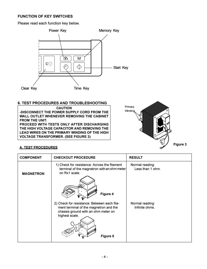

WARNING:
When removing the cabinet, you must disconnect the power supply cord from the wall outlet for your safety. Only the checkout procedure below needs the power supply on. TAKE GREAT CARE to avoid possible shock.
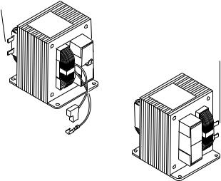
For your safety, proceed with the test only after removing the wire leads from the primary winding of the high voltage transformer.
Primary winding
Primary winding
Lower
Upper
COMPONENT |
CHECKOUT PROCEDURE |
RESULT |
|
|
|
|
|
|
|
||||
|
Check each voltage at connector S104 and S105 |
Normal reading: |
||||
POWER |
after removing each connector (female) from |
|
|
|
|
|
power circuit board. |
Connection |
|
|
|
|
|
P.C.B |
Pin No.3 (Ground) and 4,5,1,2 at S105. |
Pin No. |
|
|
Voltage |
|
|
Pin No.1 and 2 at S104. |
S105 |
|
|
|
|
|
|
#3 to #4 |
|
|
DC 12V |
|
|
CAUTION: |
#3 to #5 |
|
|
DC 16V |
|
|
Proceed with the test only after removing the |
#3 to #2 |
|
|
DC 30V |
|
|
wire leads from the primary winding of high |
#3 to #1 |
|
|
DC 35V |
|
|
voltage transformer for your safety. |
|
|
|
|
|
|
|
S104 |
|
|
|
|
|
Test procedures: |
#1 to #2 |
|
|
AC 2.4V |
|
|
a) Make sure that the power supply cord is not |
|
|
|
|
|
|
plugged in. |
|
|
|
|
|
|
b) Remove the connector S104 and S105 from |
|
|
|
|
|
|
the power circuit board. |
|
|
|
|
|
|
c) Plug the power supply cord. |
|
|
|
|
|
|
d) And then, measure each voltage. |
|
|
|
|
|
|
|
|
|
|
|
|
|
Measure the voltage: Between test points TP-1, TP- |
Test point |
|
|
|
|
|
2 ,TP-3 and ground. (See Figure 12 on page 23) |
TP |
Voltage |
|||
CONTROL |
Note |
TP-1 |
|
|
DC - 5V |
|
P.C.B |
|
|
||||
- Proceed with the check of the control P.C.B to see if |
TP-2 |
|
|
DC - 12V |
||
|
|
|
||||
|
any one of the measured values is different from the |
TP-3 |
|
|
DC - 16V |
|
|
specified values. |
TP-4 |
|
|
DC - 35V |
|
|
|
|
|
|
|
|
- 7 -
 Loading...