


INSTRUCTION MANUAL |
DWM-4500 |
DVD Home Theater System
TM
SANYO’S HELP-LINE
Call the toll-free number below if you have any difficulties operating this product. 1-800-813-3435 (Weekdays: 7:30 AM - 4:00 PM Central Time)
Please Read This Manual.
Because DVD is a new technology, we recommend that you read this manual carefully before connecting your DVD Home Theater System and operating it for the first time.
Keep the manual in a safe place for future reference.
1AD6P1P2104--A DWM-4500, Issue Number 2 |
English |
|
|

CONTENTS
Accessories ......................................................................... |
E2 |
Safety Certification ............................................................. |
E3 |
For Safe and Efficient Operation ....................................... |
E3 |
Warning for Transmitter ..................................................... |
E4 |
Controls ............................................................................... |
E5 |
Multi-Brand TV Remote Control......................................... |
E6 |
Basic Connections .............................................................. |
E8 |
System Cable Connection ............................................... |
E8 |
Speaker Connections .................................................... |
E10 |
Speaker Placement ........................................................ |
E11 |
Using the Rear Speaker in Wireless Mode ................... |
E12 |
Using the Rear Speaker in Wired Mode ........................ |
E12 |
If Using the External Speaker (Not Supplied) Instead of |
|
the Rear Speaker... ....................................................... |
E12 |
Conventional TV Connection ......................................... |
E13 |
Using RF Modulator ................................................. |
E14 |
Progressive-scan TV Connection .................................. |
E15 |
Use of your VCR and Sanyo DVD Home Theater System |
|
DWM-4500 .................................................................... |
E15 |
FM Antenna Connection ................................................ |
E16 |
Additional Connection Examples ................................... |
E16 |
Power Supply ................................................................ |
E16 |
Before Operation ............................................................... |
E17 |
Common Operation ....................................................... |
E17 |
Selecting Surround Mode .............................................. |
E18 |
Adjusting the Speaker Volume Balance ........................ |
E19 |
Adjusting the Sub-woofer Level ..................................... |
E19 |
Playable Discs ................................................................... |
E20 |
Disc Playback .................................................................... |
E21 |
Preparations .................................................................. |
E21 |
Basic Playback .............................................................. |
E22 |
Selecting Picture Mode ................................................. |
E22 |
Stopping Playback ......................................................... |
E23 |
Continuing Playback from Where You Stopped |
|
Watching (LAST MEMO PLAY), for DVD only ............... |
E23 |
Selecting a DVD Menu .................................................. |
E23 |
Selecting a Top Menu [DVD] ......................................... |
E23 |
Chapter (Track) Skip ..................................................... |
E23 |
Title Search [DVD] ......................................................... |
E24 |
Chapter Search [DVD] ................................................... |
E24 |
Time Search [DVD] ........................................................ |
E24 |
Time Search [CD] .......................................................... |
E24 |
Track Search [CD] ......................................................... |
E24 |
Fast Playback ................................................................ |
E25 |
Slow Motion Playback [DVD] ......................................... |
E25 |
Still Picture (Pause) ....................................................... |
E25 |
Frame by Frame Advance Playback [DVD]..................... |
E25 |
Picture Zoom [DVD] ...................................................... |
E25 |
Viewing from a Desired Camera Angle |
|
(Multi-Angle) [DVD] ....................................................... |
E26 |
Designated Range Repeat Playback (A-B Repeat) ...... |
E26 |
Repeat Playback ........................................................... |
E26 |
Random Playback [CD] ................................................. |
E27 |
Programmed Playback [CD] .......................................... |
E27 |
Selecting Subtitle Language [DVD] ............................... |
E28 |
Selecting Audio Soundtrack Language |
|
(Multi-Language) [DVD] ................................................. |
E28 |
Selecting On-Screen Information .................................. |
E28 |
TVGuardian Operation ...................................................... |
E29 |
Before Setting ................................................................ |
E29 |
Setting TVGuardian ....................................................... |
E29 |
How It Works After Setting TVGuardian ........................ |
E30 |
MP3/WMA CD Operation ................................................... |
E31 |
Before Starting .............................................................. |
E31 |
MP3 CD Playback ......................................................... |
E31 |
Picture Disc Operation ..................................................... |
E32 |
Before Starting .............................................................. |
E32 |
Kodak Picture/JPEG CD Playback ................................ |
E32 |
Initial Settings.................................................................... |
E33 |
Setting Language .......................................................... |
E33 |
Setting Display .............................................................. |
E34 |
Setting Audio ................................................................. |
E36 |
Setting Parental ............................................................. |
E37 |
Language Code List ...................................................... |
E38 |
Listening to the Radio (FM Only) ..................................... |
E39 |
Preparation .................................................................... |
E39 |
Automatic/Manual Tuning .............................................. |
E39 |
To Preset Stations ......................................................... |
E39 |
Listening to Preset Stations ........................................... |
E39 |
Enjoying Other Sources ................................................... |
E40 |
Sleep Timer Operation ...................................................... |
E40 |
Maintenance ...................................................................... |
E40 |
Troubleshooting Guide ..................................................... |
E40 |
Specifications .................................................................... |
E42 |
Warranty ............................................................................. |
E43 |
IMPORTANT INFORMATION:
To connect this DVD Home Theater System to a TV, TV must have a Video input jack (RCA-type) at least. You cannot connect it to an antenna terminal of TV.
To operate the built-in TVGuardian®
This unit has the built-in TVGuardian® Foul Language Filter (TVG®).
When a disc supporting closed caption is played, it will mute the audio during the entire phrase containing offensive language. For more details, see page E29.
-E1-
CAUTION
RISK OF ELECTRIC SHOCK
DO NOT OPEN
CAUTION: TO PREVENT THE RISK OF ELECTRIC SHOCK, DO NOT REMOVE COVER (OR BACK).
NO USER-SERVICEABLE PARTS INSIDE.
REFER SERVICING TO QUALIFIED SERVICE PERSONNEL.
WARNING: TO PREVENT FIRE OR SHOCK HAZARD, DO NOT EXPOSE THIS APPLIANCE TO RAIN OR MOISTURE.
Thissymbolindicatesthatdangerousvoltage constitutingariskofelectricshockispresent within this unit.
This symbol indicates that there are important operating and maintenance instructions in the literature accompanying this unit.
WARNING: UNAUTHORIZED RECORDING OF COPYRIGHTED MATERIAL MAY VIOLATE APPLICABLE COPYRIGHT LAWS. THE MANUFACTURER ASSUMES NO RESPONSIBILITY FOR UNAUTHORIZED DUPLICATION, USE OR OTHER ACTS WHICH INFRINGE UPON THE RIGHTS OF COPYRIGHT OWNERS.
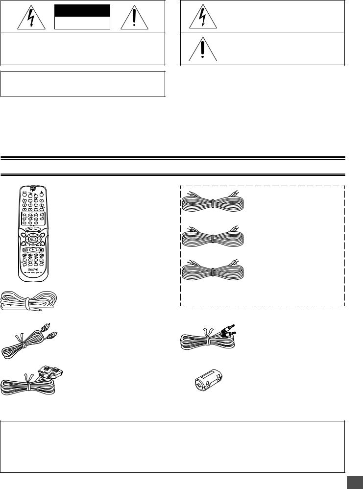
ACCESSORIES
RB-DWM4500MT wireless remote control
FM indoor antenna lead wire
Video cable
System cable
Front left speaker cable
Length: Approx. 16.4 feet (5 meters)
(Black and White)
Front right speaker cable
Length: Approx. 16.4 feet (5 meters)
(Black and Red)
Front center speaker cable
Length: Approx. 16.4 feet (5 meters)
(Black and Green)
The speaker cables are packed in the speaker package.
Assistance speaker cable for rear speaker
Length: Approx. 23 feet (7 meters)
Ferrite core x 2
Either the main unit or remote control can be operated. However, for convenience, this instruction manual explains operation using the remote control.
Note:
This handling description is printed prior to product development.
When a part of the product specification must be changed to improve operability or other functions, priority is given to the product specification itself. In such instances, the instruction manual may not entirely match all the functions of the actual product. Therefore, the actual product and packaging, as well as the name and illustration, may differ from the manual.
-E2-

SAFETY CERTIFICATION
This unit is made and tested to meet exacting safety standards. It meets UL and FCC requirements and complies with safety performance standards of the U.S. Department of Health and Human Services.
CAUTION - USE OF CONTROLS OR ADJUSTMENTS OR PERFORMANCE OF PROCEDURES OTHER THAN THOSE SPECIFIED HEREIN MAY RESULT IN HAZARDOUS RADIATION EXPOSURE.
THISUNITSHOULDNOTBEADJUSTEDORREPAIRED BY ANYONE EXCEPT PROPERLY QUALIFIED SERVICE PERSONNEL.
FCC INFORMATION
This device complies with Part 15 of the FCC Rules. Operation is subject to the following two conditions:
(1) This device may not cause harmful interference, and (2) this device must accept any interference received, including interference that may cause undesired operation.
CAUTION:
Changes or modifications not expressly approved by the party responsible for compliance could void the user’s authority to operate this equipment.
Note:
This equipment has been tested and found to comply with the limits for a Class B digital device, pursuant to Part 15 of the FCC Rules. These limits are designed to provide reasonable protection against harmful interference in a residential installation. This equipment generates, uses and can radiate radio frequency energy and, if not installed and used in accordance with the instructions, may cause harmful interference to radio communications. However, there is no guarantee that interference will not occur in a particular installation. If this equipment does cause harmful interference to radio or television reception, which can be determined by turning the equipment off and on, the user is encouraged to try to correct the interference by one or more of the following measures:
•Reorient or relocate the receiving antenna.
•Increase the separation between the equipment and receiver.
•Connect the equipment into an outlet on a circuit different from that to which the receiver is connected.
•Consult the dealer or an experienced radio/TV technician for help.
FOR SAFE AND EFFICIENT OPERATION
•Do not damage the power cord.
•When not in use, disconnect the power cord from the outlet. Grasp the plug, not the cord, when disconnecting the unit.
•If water should enter the unit, electrical shock or a malfunction may result. Use in an area where there is low humidity and little dust.
•Do not disassemble or alter the unit in any way.
•Do not use the unit in areas where extremes in temperature occur (below 40°F (5°C) or exceeding 95°F (35°C)), or where it may be exposed to direct sunlight.
•Because of the DVD video player’s extremely low noise and wide dynamic range, there is a tendency to set the volume on the amplifier higher than necessary. Doing so may produce an excessively high output from the amplifier which can cause damage to your speakers. Please be careful in this regard.
•Sudden changes in the surrounding temperature can cause dew to form on the optical pickup lens inside the unit. Under this condition the unit may be unable to operate properly. If this should occur, remove the disc and allow the unit to adjust to the surrounding temperature.
•When carrying the unit, be sure to remove a disc which may be inside and turn the power off. Then unplug the power cord from the AC outlet after 10 seconds. Carrying the unit with a disc inside may damage the disc and/or the unit.
•The unit is automatically set to the Screen Saver mode after approximately 5 minutes have elapsed under the stop or pause mode.
CAUTION:
The sub-woofer (powered speaker) and the rear speaker (powered speaker) must be placed in a well ventilated area. Do not place any object on the top of these units.
Do not block ventilation holes.
The cabinet of these units warms up when it is used for a long time, but it is not a malfunction.
-E3-
WARNING FOR TRANSMITTER
Important Information!
1.Explicitly specify to all users the technical instructions and the scope of use defined in the related documents and provide the explanation about all the control methods, adjusting procedures and usage of switches.
2.Do not change the emitter frequency nor boost the emitter power (including the power of excess load wireless frequency power amplifier). Do not put up an external antenna nor use any other remodeled antenna.
3.In use of this unit, avoid any act which interferes with legal wireless communication services. Should any interference arise, immediately stop using this unit, remove the interference, and avoid such an act in the future.
4.When micro-power wireless equipment is used, avoid interference with wireless communication services or emissive interference from industrial, scientific and medical treatment equipment.
5.Do not use this unit in an aircraft or near an airport.
Warning for using the sub-woofer with a builtin transmitter
•Keep the sub-woofer (powered speaker) at least 8 feet away from all heart pacemakers!
The radio waves may disrupt the operation of the pacemaker.
•Do not operate this unit in medical Institutions, hospitals or near medical equipment!
The radio waves may cause nearby equipment to operate incorrectly or fail.
Forbidden
•When other equipment or a medical apparatus operates incorrectly or fails to operate due to radio wave interference, stop using this unit!
The radio waves may cause nearby equipment to operate incorrectly or fail.
Forbidden
In-plant radio stations, and special low-power radio stations for movable body identification used for production lines and amateur radio stations as well as industrial, scientific and medical equipment (such as microwave ovens) use the same frequency band used by this unit.
1.Before using this unit, make sure that no in-plant radio stations or special low-power radio stations for movable body identification or amateur radio stations are operated nearby.
2.If this unit should adversely radio-interfere with an in-plant radio station for movable body identification, immediately change the frequency band used by this unit or stop emitting electric waves and consult the your dealer or SANYO service center about measures for avoiding interference (for example, installation of a partition).
3.If any trouble occurs such as this unit causing adverse radio interference with special low-power radio stations for movable body identification or an amateur radio station, contact your SANYO dealer or SANYO service center.
-E4-
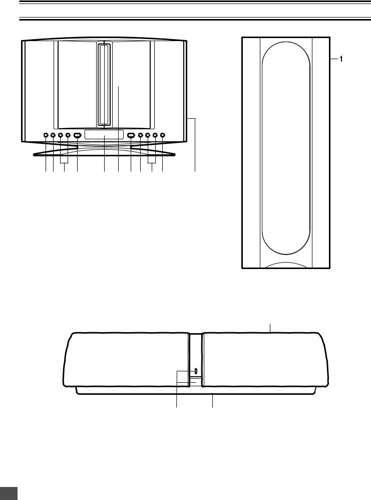
CONTROLS
Main unit (DVD Receiver) |
Sub-woofer (Powered speaker) |
1 2 |
3 |
4 |
5 |
6 |
7 |
8 |
9 10 |
1.Remote sensor (IR)
2.Function button (FUNCTION)
3.Volume buttons (- VOL +)
4.Power button (z/ON)
5.Display
6.Disc door
7.Play button (a)
8.Stop button (n)
9.Skip/Next/Previous/Preset tuning buttons (f/e, -PRESET +)
10.Open/Close button (q)
11.S-video and Component video out select switch (VIDEO OUT SELECT, right side)
(See pages E13 and E15.)
Rear speaker (Powered speaker)
11
1. Frequency switch (FREQUENCY, back side) (See page E12.)
3
1
1.Power switch (z/ON) and power indicator
2.Speaker switch (SPEAKER, back side) (See page E12.)
2
3. Frequency switch (FREQUENCY, top side) (See page E12.)
-E5-
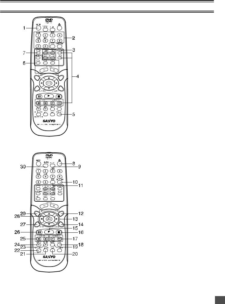
MULTI-BRAND TV REMOTE CONTROL
1.Power button (z/ON)
2.Number and other function buttons
These buttons are used as number buttons and as function buttons of each name.
•When using as a number button, press the appropriate button directly.
•When using as a function button of each name, press the appropriate button while holding the SHIFT button down.
Number buttons (1 – 9, 0)
Angle button (ANGLE)
Zoom button (ZOOM)
Audio button (AUDIO)
Sleep button (SLEEP)
3.TV control buttons
Power button (TV POWER) TV/VIDEO select button (TV/VIDEO) Channel scanning buttons (-TV CH +)
4.Tuner controls
FM mode button (FM MODE) Tuner function button (TUNER) Tuning buttons (- TUNE +)
Preset tuning buttons (- PRESET +)
5.Function button (FUNCTION)
6.Amplifier controls
Surround button (SURROUND) Muting button (MUTE)
Bass button (BASS)
Sound preset button (SOUND) Volume buttons (- VOLUME +)
7.Shift button (SHIFT)
8.Open/Close button (q)
9.Return button (RETURN) (See page E23.)
10.Clear/Trim button (CLEAR, TRIM) Note:
At Trimming mode, press the button while holding the SHIFT button down. (See page E19.)
11.Test tone button (TEST) (See page E19.)
12.Menu button (MENU)
13.Directional arrow buttons (o, a, p, b)
14.On-screen display button (ON SCREEN)
15.Play button (a)
16.Stop button (n)
17.Skip/Next/Previous buttons (f, e)
18.Repeat button (REPEAT)
19.A-B repeat button (A-B REP)
20.Subtitle change button (S.T.CH)
21.Last memory button (L.MEMO)
22.Picture mode/Search mode button (PICTURE MODE/SEARCH MODE) Note:
At Search mode, press the button while holding the SHIFT button down.
23.Forward slow button (F.SLOW I a)
24.Reverse slow button (R.SLOW b I)
25.Fast forward/Fast reverse buttons (d, c)
26.Pause/Step button (k)
27.Top menu button (TOP MENU)
28.Enter button (ENTER)
29.Setup button (SETUP)
30.Program/Random play button (PROGRAM/RANDOM)
-E6-
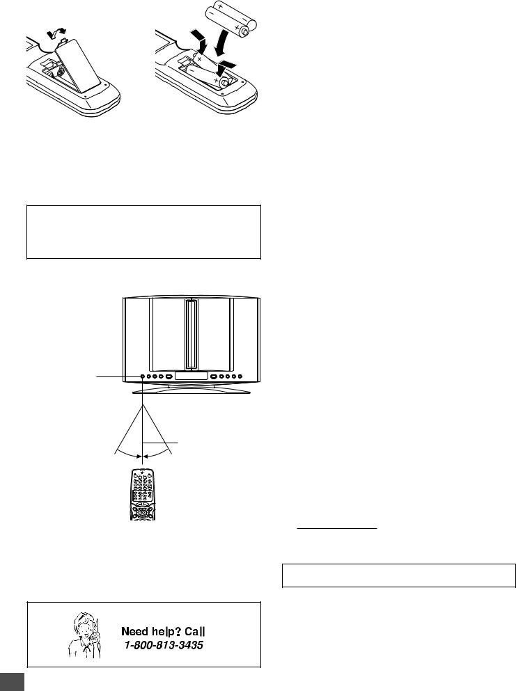
Inserting batteries
1 |
2 |
Two "AA" batteries
(not supplied)
Note:
Remove the batteries if the remote control is not to be used for a month or more. Batteries left in the unit may leak and cause damage.
IMPORTANT NOTE:
SPENT OR DISCHARGED BATTERIES MUST BE RECYCLED OR DISPOSED OF PROPERLY IN COMPLIANCE WITH ALL APPLICABLE LAWS.
FOR DETAILED INFORMATION, CONTACT YOUR LOCAL COUNTY SOLID WASTE AUTHORITY.
Remote control range
Remote sensor
Within approx. 20 feet

 (6 meters) 30°
  30°
30°
To set the remote control code for TV
This remote control can operate the basic functions of TVs made by the manufacturers listed below.
To enter the remote control code for your brand of TV, follow the steps below.
1.In the chart below, find the code corresponding to your brand of TV.
2.While holding down [TV POWER], enter the 2-digit code using the number buttons [0 - 9], then release [TV POWER].
• The remote control is now set to operate your TV.
TV brands |
Code |
|
|
|
|
ADMIRAL |
05, |
10, 13 |
|
|
|
EMERSON |
17 |
|
FISHER |
03 |
|
|
|
|
GE |
07 |
|
|
|
|
GOLD STAR |
01 |
|
|
|
|
HITACHI |
02 |
|
|
|
|
JVC |
15 |
|
|
|
|
MAGNAVOX |
08 |
|
MATSUSHITA |
12, |
18 |
|
|
|
MITSUBISHI |
14 |
|
PANASONIC |
12, |
18 |
|
|
|
QUASAR |
12, |
18 |
|
|
|
RCA |
06 |
|
|
|
|
SAMSUNG |
16 |
|
|
|
|
SANYO |
03 |
|
|
|
|
SHARP |
00, |
13 |
|
|
|
SONY |
11 |
|
|
|
|
TECHNOL ACE |
05 |
|
|
|
|
TOSHIBA |
04 |
|
|
|
|
ZENITH |
09, |
10 |
|
|
|
Notes:
•Only remote-controlled TVs can be operated using this remote control. (Refer to your TV instruction manual for more details.)
•There may be some TV models that cannot be operated with this remote control. If this is the case, use the original remote control supplied with the TV.
IMPORTANT NOTE:
If the batteries in the remote control are changed, the code settings for the TV must be re-entered.
Write your code number below for future reference.
TV:
Note:
This remote control cannot operate your VCR.
-E7-

BASIC CONNECTIONS
Do not connect the power cord to a 120V AC 60Hz outlet until all connections have been made.
System Cable Connection
Main unit (DVD Receiver)
System cable 
Sub-woofer (Powered speaker)
System cable from Main unit (DVD Receiver)
System cable to Sub-woofer (Powered speaker)
Attach the ferrite core.
Ferrite core 
-E8-
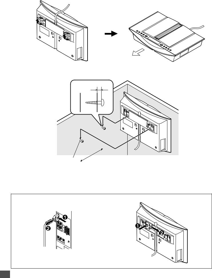
Example: To use Main unit horizontally
Toward you
Example: To hang Main unit on a wall
Approx. 3/16 inch (5mm)
|
|
|
|
|
|
Round head screw (not supplied) |
Approx. 5.4 inch (144mm) |
|
|
|
|
|
|
|
Note:
Take care when installing it. It may cause damage or serious injury should it fall from its mountings.
To unplug the system cable, pull out the plug (2) while pressing (1) down. |
|
Sub-woofer (Powered speaker) |
Main unit |
-E9-
Note:
Do not connect the power cord to a 120V AC 60Hz outlet until all connections have been made.
Speaker Connections
To achieve proper stereo reproduction, connect the speaker wires without shorting to adjacent wires as shown below.
Speaker Wire Color |
Use |
|
Black and White |
Front left speaker |
|
Black and Red |
Front right speaker |
|
Black and Green |
Center speaker |
|
|
|
|
Front left speaker |
|
|
|
Center speaker |
|
|
|
Front right speaker |
|
|
|
|
|
|
|
|||||||||||||||
|
|
|
|
|
|
|
|
|
|
|
|
|
|
|
|
|
|
|
|
|
|
|
|
|
|
|
|
|
|
|
|
|
|
|
|
|
|
|
|
|
|
|
|
|
|
|
|
|
|
|
|
|
|
|
|
|
|
|
|
|
|
|
|
|
|
|
|
|
|
|
|
|
|
|
|
|
|
|
|
|
|
|
|
|
|
|
|
|
|
|
|
|
|
|
|
|
|
|
|
|
|
|
|
|
|
|
|
|
|
|
|
|
|
|
|
|
|
|
|
|
|
|
|
|
|
|
|
|
|
|
|
|
|
|
|
|
|
|
|
|
|
|
|
|
|
|
|
|
|
|
|
|
|
|
|
|
|
|
|
|
|
|
|
|
|
|
|
|
|
|
|
|
|
|
|
|
|
|
|
|
|
|
|
|
|
Black |
Red |
FRONT
CENTER
SPEAKERS(4Ω)
Main unit (DVD Receiver)
SYSTEM (TO DVD RECEIVER)
System cable
Ferrite core
After all speaker
connections have been Sub-woofer (Powered speaker) made, attach the ferrite
core.
Ferrite core 


-E10-
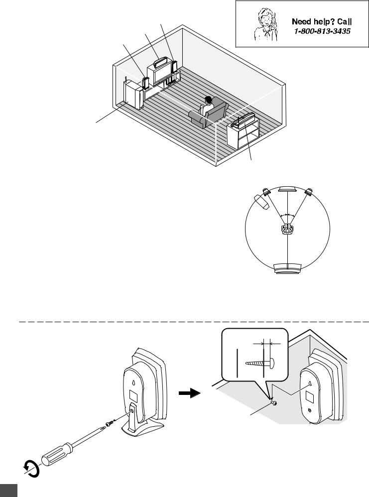
Speaker Placement
Front right speaker
Center speaker
Front left speaker
Sub-woofer (Powered speaker)
Place it near the front speaker. However, do not place it in front of the TV.
The front (left and right) and center speakers have built-in magnetic stray field compensation. They may be placed close to a TV without affecting the color purity.
Place the front left and right speakers either side of the TV. Place the center speaker directly above the TV.
The front, center, and rear speakers should be placed at approximately the same distance from the listening position. Place the rear speaker behind the listening position, on the floor or approximately 2 feet ~ 3 feet 3 inches (60 cm ~ 1 meter) higher than ear level.
Keep enough distance between the subwoofer and the TV so as not to garble the TV screen.
Example: To hang the speaker on a wall
Unscrew and remove the stand.
Rear speaker (Powered speaker)
Center speaker
Front left speaker |
Front right speaker |
Sub-woofer
30° 30°
Rear speaker
Notes:
•The angles in the diagram are approximate.
•Please refer to “Setting Audio” on page E36.
•Set the TV’s built-in speaker volume to minimum.
Approx. 1/8 inch (3 mm)
Round head screw (not supplied)
Note:
Take care when installing the speakers. They may cause damage or serious injury should they fall from their mountings.
Keep both the screw and stand for future use.
-E11-
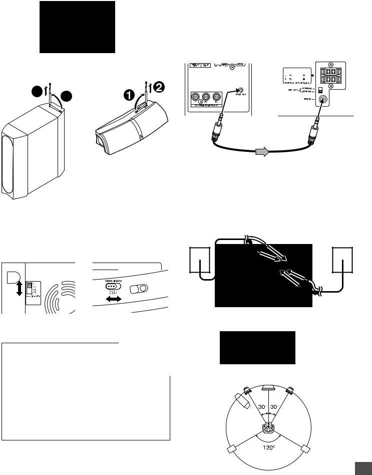
Using the Rear Speaker in Wireless Mode
1.Set the SPEAKER switch of the rear speaker to the INTERNAL position.
Rear speaker (Powered speaker)
2.Pull out gently the antenna vertically.
• Try not to hold, bend, or twist the antenna.
2 |
1 |
|
Rear speaker (Powered speaker)
Sub-woofer (Powered speaker)
CAUTION:
Keep it out of reach of young children who might damage it.
3.Set the FREQUENCY switch to “1”, “2”, “3” or “4”.
Match the number on both sub-woofer and rear speaker.
Sub-woofer |
Rear speaker |
(Powered speaker) |
(Powered speaker) |
Changing the frequency setting
If noise (or skipping sound) is heard when using rear speaker in wireless mode, change the setting of the FREQUENCY switch on both sub-woofer and rear speaker.
Match the number on both sub-woofer and rear speaker. It may improve the sounds.
The following four frequencies are available.
FREQUENCY switch
1(914.1 MHz)
2(914.5 MHz)
3(914.9 MHz)
4(915.3 MHz)
Using the Rear Speaker in Wired Mode
Because the rear speaker is the wireless type, it is not necessary to connect the assistant speaker cable under normal connections. If noise is caused to the rear speaker when used in wireless mode, change the setting of the FREQUENCY switch on both sub-woofer and rear speaker (Refer to the left column).
If noise is still caused, turn the power off first and connect the rear speaker to the sub-woofer using the supplied assistant speaker cable. In this case, the audio signal is sent to the rear speaker through the assistant speaker cable.
Sub-woofer (powered speaker) |
Rear speaker (Powered |
|
speaker) |
||
|
To REAR OUT |
To REAR IN |
jack |
jack |
Assistant speaker cable |
|
Note:
Adjust the distances between the sub-woofer and the rear speaker to be suitable shorter than approx. 23 feet cord length.
If Using the External Speaker (Not Supplied)
Instead of the Rear Speaker...
1.Connect the external speaker (4 Ω, more than 50 Watts for each speaker, not supplied) to the EXTERNAL SPEAKERS terminal.
External rear left speaker
(not supplied) External rear right speaker (not supplied)
2.Set the SPEAKER switch to the EXTERNAL position.
3.Place the external speaker as shown in figure.
Center speaker
Front left speaker |
Front right speaker |
Sub-woofer
External rear |
External rear |
left speaker |
right speaker |
(not supplied) |
(not supplied) |
-E12-
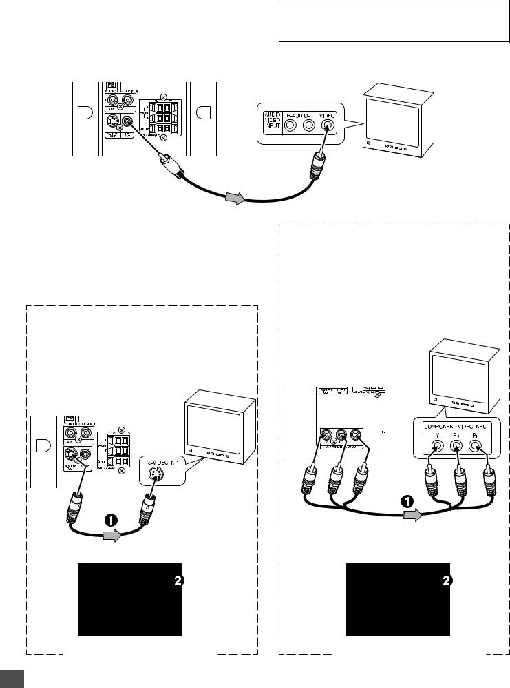
Conventional TV Connection
Using VIDEO OUT jack
Connect the Video cable with yellow connectors (supplied) between the VIDEO OUT jack of the sub-woofer and the VIDEO INPUT jack on the TV.
Sub-woofer (Powered speaker)
Important Information:
To connect the unit to a TV, TV must have a Video input jack (RCA-type) at least. You cannot connect it to an antenna terminal of TV.
To VIDEO INPUT jack
TV
To VIDEO OUT jack (Yellow) 
Video cable (supplied)
Notes:
•Please refer to your TV instruction manual.
•When you connect the subwoofer to your TV, be sure to turn off the power and disconnect both units from the wall outlet until all the connections have been made.
•Do not connect the VIDEO OUT, S-VIDEO OUT, and COMPONENT VIDEO OUT jacks of the sub-woofer to a VCR directly. The playback picture will be distorted because DVD video discs are copy protected.
Using S-VIDEO OUT jack Note:
Please follow the steps before turning on the power.
1.If your TV has the S-VIDEO INPUT jack, connect the *S- video cable (not supplied) as shown in figure. (The VIDEO OUT jack connection is not necessary.)
You can enjoy clearer picture playback.
Sub-woofer (Powered speaker)
TV with S-VIDEO
INPUT jack
*S-video cable (not supplied)
2. Set the VIDEO OUT SELECT switch to the S-VIDEO position.
Using COMPONENT VIDEO OUT jacks Note:
Please follow the steps before turning on the power.
1.If your TV has the COMPONENT VIDEO INPUT jacks, connect the *Component video cable (not supplied) as shown in figure.
(The VIDEO OUT or S-VIDEO OUT jack connection is not necessary.)
You can enjoy high quality picture playback.
TV with COMPONENT
VIDEO INPUT jacks
Sub-woofer (Powered speaker)
Green |
Blue |
Red |
Green |
Blue |
Red |
*Component Video cable (not supplied)
2.Set the VIDEO OUT SELECT switch to the COMPONENT position.
Main unit (Right side) |
Main unit (Right side) |
*Please consult your local audio/video dealer.
-E13-
 Loading...