


SERVICE MANUAL |
Remote Control Color |
|
Television |
AS
FILE NO.
DS27800 (U.S.A.) (CANADA)
ORIGINAL VERSION
Chassis No. 27800-00
NOTE: Match the Chassis No. on the unit’s back cover with the Chassis No. in the Service Manual.
If the Original Version Service Manual Chassis No. does not match the unit’s, additional Service Literature is required. You must refer to “Notices” to the Original Service Manual prior to servicing the unit.
Contents |
|
Specifications |
|
Safety Instructions . . . . . . . . . . . . . . |
. . . . 2 |
Power Rating . . . . . . . . . . |
. . . . . . . . . . . 120V, 60Hz |
Service Adjustments . . . . . . . . . . . . . |
. 3 - 8 |
|
86W (Avg), 2.5A (Max) |
Service Hints . . . . . . . . . . . . . . . . . . . |
. . . . 9 |
Antenna Input Impedance . |
. . . . . . . . . . . . . . . . 75Ω |
Mechanical Disassemblies. . . . . . . . |
. . . 10 |
|
UHF/VHF/CATV |
Chassis Electrical Parts List . . . . . . |
11 - 21 |
Receiving Channel . . . . . . . |
. . . . . . . . . 2 - 13 (VHF), |
Cabinet Parts List . . . . . . . . . . . . . . . |
. . . 22 |
|
14 - 69 (UHF), |
Component and Test Point |
|
|
01, 14-94, 95-125 (CATV) |
Locations . . . . . . . . . . . . . . . . . . . |
23 - 24 |
Remote Ready . . . . . . . . . . |
38 Key Remote Control |
Schematic Insert . . . . . . . . . . . . . . . |
25 - 32 |
Sound Output . . . . . . . . . . |
. . . . . . . . . . . . 3.0 W/CH |
Schematic Notes . . . . . . . . . . . . . . |
. . . 25 |
Intermediate Frequency |
|
Pin Layouts . . . . . . . . . . . . . . . . . . |
. . . 25 |
Picture IF Carrier. . . . . . . |
. . . . . . . . . . . 45.75MHz |
Capacitor and Resistor Codes . . . |
. . . 25 |
Sound IF Carrier . . . . . . . |
. . . . . . . . . . . 41.25MHz |
Block Diagram . . . . . . . . . . . . . . . |
26 - 27 |
Color Sub Carrier . . . . . . |
. . . . . . . . . . . 42.17MHz |
Voltage Charts . . . . . . . . . . . . . . . |
26 - 28 |
Picture Tube . . . . . . . . . . . . |
. . . . . . . A68AJB82X04 |
Waveforms. . . . . . . . . . . . . . . . . . . |
. . . 28 |
Semiconductors |
|
Schematic Diagrams . . . . . . . . . . |
29 - 32 |
Integrated Circuits. . . . . . |
. . . . . . . . . . . . . . . . . 13 |
|
|
Transistors. . . . . . . . . . . . |
. . . . . . . . . . . . . . . . . 48 |
|
|
Except within Tuner and RC Pre-Amp. |
|
|
|
Cabinet Dimensions |
|
|
|
Width. . . . . . . . . . . . . . . . |
. . . . . . . . . . . . . 664mm |
|
|
Height . . . . . . . . . . . . . . . |
. . . . . . . . . . . . . 629mm |
|
|
Depth. . . . . . . . . . . . . . . . |
. . . . . . . . . . . . . 503mm |
DS27800, G5MRM, PRODUCT CODE 111336193 |
REFERENCE No. SM780069 |

SAFETY INSTRUCTIONS
SAFETY PRECAUTIONS
WARNING: The chassis of this receiver has a floating ground with the potential of one half the AC line voltage in respect to earth ground. Service should not be attempted by anyone not familiar with the precautions necessary when working on this type of equipment.
The following precautions must be observed:
1.An isolation transformer must be connected in the power line between the receiver and the AC line before any service is performed on the receiver.
2.Comply with all caution and safety-related notes provided on the side of the cabinet, inside the cabinet, on the chassis, and the picture tube.
3.When replacing a chassis in the cabinet, always be certain that all the protective devices are installed properly, such as control knobs, adjustment covers, shields and barriers.
DO NOT OPERATE THIS TELEVISION RECEIVER WITHOUT THE PROTECTIVE SHIELD IN POSITION AND PROPERLY SECURED.
4.Before replacing the back cover of the set, thoroughly inspect the inside of the cabinet to see that no stray parts or tools have been left inside.
Before returning any television to the customer, the service technician must perform the following safety checks to be sure that the unit is completely safe to operate without danger of electrical shock.
ANTENNA COLD CHECK
Remove AC plug from the 120 VAC outlet and place a jumper across the two blades. Connect one lead of an ohmmeter to the jumpered AC plug, and touch the other lead to each exposed antenna terminal (UHF and VHF antenna terminals). The resistance must measure between 1M ohm and 5.2M ohm. Any resistance value below or above this range indicates an abnormality which requires corrective action.
LEAKAGE CURRENT CHECK
Plug the AC line cord directly into a 120 VAC outlet. (Do not use an isolation transformer for this check.) Use an AC voltmeter, that has 5000 ohms per volt or more sensitivity. Connect a 1500 ohm 10 watt resistor, paralleled by a 0.15 µF 150 VAC capacitor, between a known good earth ground (water pipe, conduit, etc.) and all exposed metal parts of the cabinet (antennas, handle bracket, metal cabinet, screw heads, metal overlays, control shafts, etc.). Measure the AC voltage across the 1500 ohm resistor. The AC voltage should not exceed 750 mV. A reading exceeding 750 mV indicates that a dangerous potential exists. The fault must be located and corrected. Repeat the above test with the receiver power plug reversed.
NEVER RETURN A RECEIVER TO THE CUSTOMER WITHOUT TAKING THE NECESSARY CORRECTIVE ACTION.
X-RADIATION PRECAUTION
The primary source of X-RADIATION in solid-state receivers is the picture tube. The picture tube is specially constructed to limit X-Ray emission. For continued X-RADIATION protection, the replacement tube must be the same type as the original (including the suffix letter in the part numbers). Excessive high voltage may produce potentially hazardous X-RADIATION. To avoid such hazards, the high voltage must be maintained within specific limits. Refer to the X-RADIATION WARNING NOTE on the CHASSIS SCHEMATIC in this service manual for specific high voltage limits. If the high voltage exceeds specified limits, check the components specified on the chassis schematic diagram and take the necessary corrective action. Carefully follow the instructions for the +B Voltage Check and the High Voltage Check to maintain the high voltage within the specified limits.
HIGH VOLTAGE HOLD-DOWN TEST
To prevent X-RADIATION from the picture tube due to excessive high voltage, a HOLD-DOWN circuit is provided in the high voltage circuit. Every time the receiver is serviced, the high voltage HOLD-DOWN circuit must be tested for proper operation. Refer to the HIGH VOLTAGE HOLDDOWN TEST in service adjustments.
PRODUCT SAFETY NOTICE
When replacing components in a receiver, always keep in mind the necessary product safety precautions. Pay special attention to the replacement of components marked with a star ( ) in the parts list and in the schematic diagrams. To ensure safe product operation, it is necessary to replace those components with the exact same PARTS.
— 2 —

SERVICE ADJUSTMENTS
GENERAL
This set has an On-screen Service Menu system included in the CPU that allows remote operation for most of the service adjustments.
IC802 (EEPROM) REPLACEMENT
When IC802 (EEPROM) is replaced, IC801 (CPU) will automatically write the initial reference data into IC802 for basic TV operation. However, the bus data should be checked and some bus data should be set up before attempting the service adjustments. (See pages 4 – 5 for detailed information.)
INITIAL BUS DATA SETUP
Note: When IC802 (EEPROM) is replaced, the Service Menu NO. 01 HP (H-Phase), NO. 14 AF (Auto Flesh), NO. 24 AG (AFC Gain), NO. 26 SCO (Sub Color), NO. 27 STI (Sub-Tint), NO. 29 OPT (Option 1), NO. 30 OP2 (Option 2), NO. 31 HR (OSD Display H-Position), NO. 38 SBO (Sub Bright Offset), NO. 39 PCO (PIP Color), NO. 40 PTI (PIP Tint), and NO. 45 PCN (PIP Contrast) should be set up for proper TV operation before attempting the service adjustments.
1.Disconnect the AC power cord (AC 120V line).
2.While pressing the MENU key, reconnect the AC power cord. The Service Menu display will now appear.
3.Select NO. 01 HP (H-Phase) with ▲ or ▼ key. Adjust the data with + or – key for 19.
4.Select NO. 14 AF (Auto Flesh) with ▲ or ▼ key. Adjust the data with + or – key for 1.
5.Select NO. 24 AG (AFC Gain) with ▲ or ▼ key. Adjust the data with + or – key for 0.
6.Select NO. 26 SCO (Sub Color) with ▲ or ▼ key. Adjust the data with + or – key for 7.
7.Select NO. 27 STI (Sub Tint) with ▲ or ▼ key. Adjust the data with + or – key for 19.
8.Select NO. 29 OPT (Option 1) with ▲ or ▼ key. Adjust the data with + or – key for 80.
9.Select NO. 30 OP2 (Option 2) with ▲ or ▼ key. Adjust the data with + or – key for 55.
10.Select NO. 31 HR (OSD Display H-Position) with ▲ or ▼ key. Adjust the data with + or – key for 47.
11.Select NO. 38 SBO (Sub Bright Offset) with ▲ or ▼ key. Adjust the data with + or – key for 3.
12.Select NO. 39 PCO (PIP Color) with ▲ or ▼ key. Adjust the data with + or – key for 39.
13.Select NO. 40 PTI (PIP Tint) with ▲ or ▼ key. Adjust the data with + or – key for 41.
14.Select NO. 45 PCN (PIP Contrast) with ▲ or ▼ key. Adjust the data with + or – key for 44.
15.Press the MENU key to turn off the Service Menu display.
ON-SCREEN SERVICE MENU SYSTEM
1.Enter the Service Menu:
•While pressing the MENU key, reconnect the AC power cord. The Service Menu Display will now appear. (See Figure 1 below.)
NO. DATA
XX OPT XXX XXXXXXXX
|
|
|
|
|
|
|
|
|
|
|
|
|
|
|
|
|
|
|
|
|
|
TITLE |
|
|
|
|
|
||
|
|
|
|
BINARY DATA |
|||||
|
|
|
|
|
|
|
(8 bit) |
||
ITEM NO. |
DECIMAL DATA |
||||||||
Figure 1. Service Menu Display
2.Service Adjustments:
•Press the ▲ or ▼ key to select the desired service menu you want to adjust. (See page 4 for On-screen Service Menu.)
•Use the + or – key to adjust the data.
3.Exit from the Service Menu:
•Press the MENU key to turn off the Service Menu display.
— 3 —
Table 1. ON-SCREEN SERVICE MENU
When IC802 (EEPROM) is replaced, check the bus data to confirm they are the same as below. The shaded menu should be checked and be set up or readjusted according to the procedures described in the following pages. Initial Setup Data marked with an * should be changed from Initial Reference Data. (See page 3 for Initial Bus Data Setup.)
NO. |
TITLE |
INITIAL REFERENCE |
INITIAL SETUP |
RANGE OF DATA |
|
FUNCTION |
|
||
DATA |
DATA |
|
|
||||||
|
|
|
|
|
|
|
|||
01 |
HP |
15 |
19* |
0~31 |
H-Phase (H-Centering) |
|
|
||
02 |
IAS |
0 |
0 |
0, 1 |
IF AGC Switch |
0: TV (Normal) 1: AV (IF Gain Minumum) |
|||
03 |
RAD |
25 |
25 |
0~63 |
RF AGC Delay |
|
|
|
|
04 |
PT |
64 |
64 |
0~127 |
PLL Tuning |
|
|
|
|
05 |
ADA |
31 |
31 |
0~63 |
APC Detect Adjust |
|
|
||
06 |
CD |
0 |
0 |
0, 1 |
C-Diff |
|
|
|
|
07 |
VS |
32 |
32 |
0~63 |
Vertical Size |
|
|
|
|
08 |
RB |
0 |
0 |
0~255 |
Red Bias |
|
|
|
|
09 |
GB |
0 |
0 |
0~255 |
Green Bias |
|
|
|
|
10 |
BB |
0 |
0 |
0~255 |
Blue Bias |
|
|
|
|
11 |
RD |
60 |
60 |
0~127 |
Red Drive |
|
|
|
|
12 |
BD |
60 |
60 |
0~127 |
Blue Drive |
|
|
|
|
13 |
TDS |
0 |
0 |
0, 1 |
Trap & D (B.P.F.) Switch |
0: OFF 1: ON |
|||
14 |
AF |
0 |
1* |
0, 1 |
Auto Flesh |
0: OFF 1: ON |
|
||
15 |
BS |
0 |
0 |
0, 1 |
Black Stretch |
0: OFF 1: ON |
|
||
16 |
VL |
4 |
4 |
0~7 |
Video Level |
|
|
|
|
17 |
FL |
15 |
15 |
0~31 |
FM Level |
|
|
|
|
18 |
NIS |
1 |
1 |
0, 1 |
N/I Switch (Black Noise Inverter) |
0: OFF 1: ON |
|||
19 |
ABL |
1 |
1 |
0,1 |
ABL Defeat |
|
0: OFF 1: ON |
||
20 |
WP |
1 |
1 |
0,1 |
White Peak Limiter |
0: OFF 1: ON |
|||
21 |
GD |
7 |
7 |
0~15 |
Green Drive Reduction |
|
|
||
22 |
VC |
0 |
0 |
0~7 |
Vert. Comp |
|
|
|
|
23 |
VD |
32 |
32 |
0~63 |
Vert. DC |
|
|
|
|
24 |
AG |
3 |
0* |
0~3 |
AFC Gain |
00: Auto 01: High Gain 10: Low Gain 11: Non-Gate |
|||
25 |
SB |
32 |
32 |
0~63 |
Sub-Brightness |
|
|
|
|
26 |
SCO |
10 |
7* |
0~31 |
Sub-Color |
|
|
|
|
27 |
STI |
14 |
19* |
0~31 |
Sub-Tint |
|
|
|
|
28 |
SSH |
8 |
8 |
0~15 |
Sub-Sharpness |
|
|
|
|
|
|
|
|
|
|
|
|||
29 |
OPT |
0 |
80* |
0~255 |
Option 1 |
(See Note 1 page 5.) |
|||
30 |
OP2 |
0 |
55* |
0~255 |
Option 2 |
(See Note 2 page 5.) |
|
||
31 |
HR |
43 |
47* |
0~63 |
H-Position (OSD H-Position) |
|
|||
32 |
ATT |
15 |
15 |
0~15 |
Attenuation |
|
|
|
|
33 |
STE |
— |
— |
— |
Not Used |
|
|
|
|
34 |
FIL |
— |
— |
— |
Not Used |
|
|
|
|
35 |
WDB |
32 |
32 |
0~63 |
Wideband |
|
|
|
|
36 |
SPC |
32 |
32 |
0~63 |
Spectral |
|
|
|
|
37 |
SPV |
— |
— |
— |
Not Used |
|
|
|
|
38 |
SBO |
5 |
3* |
0~255 |
Sub Bright Offset |
|
|
|
|
39 |
PCO |
42 |
39* |
0~127 |
PIP Color |
|
|
|
|
40 |
PTI |
36 |
41* |
0~63 |
PIP Tint |
|
|
|
|
41 |
PUV |
24 |
24 |
0~255 |
PIP Upper Vertical Position |
|
|
||
42 |
PDV |
147 |
147 |
0~255 |
PIP Lower Vertical Position |
|
|
||
43 |
PLH |
9 |
9 |
0~255 |
PIP Left Side Horizontal Position |
|
|||
44 |
PRH |
99 |
99 |
0~255 |
PIP Right Side Horizontal Position |
|
|||
45 |
PCN |
47 |
44* |
0~127 |
PIP Contrast |
|
|
|
|
46 |
PBS |
14 |
14 |
0~63 |
PIP Burst Gate Position |
|
|
||
|
|
|
|
|
|
|
|||
47 |
DRV |
55 |
60* |
0~127 |
Red Drive Adjustment |
(See Note 3 page 5.) |
|||
55 |
60* |
0~127 |
Blue Drive Adjustment |
(See Note 3 page 5.) |
|||||
|
|
||||||||
|
– |
0 |
0 |
0~255 |
Red Bias Adjustment |
(See Note 4 page 5.) |
|||
48 |
– |
0 |
0 |
0~255 |
Green Bias Adjustment |
(See Note 4 page 5.) |
|||
|
– |
0 |
0 |
0~255 |
Blue Bias Adjustment |
(See Note 4 page 5.) |
|||
— 4 —

SERVICE ADJUSTMENTS (Continued)
PROGRAM CODES
The microprossesor used in this model is a multi-purpose type and is used in several different models. To ensure proper operation and the correct features for your particular model, the Program Codes must be correct.
Note 1. Option Data 1 (NO. 29 OPT) should be decimal 80 (01010000 binary). See page 3 INITIAL DATA SETUP, step 8, for set up procedure. If this program code is wrong the TV will not operate properly.
BIT |
FUNCTION |
DATA |
|||
0 |
|
1 |
|||
|
|
|
|||
|
TV |
00: TV |
|
||
0, 1 |
HOTEL |
01: HOTEL |
|
||
|
MONITOR |
10: MONITOR (*1) |
|||
|
|
11: INHIBITED (=TV) |
|||
2 |
VIDEO INPUT |
NONE (*2) |
|
YES |
|
|
|
|
|
|
|
|
|
00: NONE |
|
||
3, 4 |
CLOCK |
01: YES (AC 60 HZ) |
|||
10: YES (INT OSC) |
|||||
|
|
||||
|
|
11: INHIBITED (=NONE) |
|||
5 |
STEREO/MONO |
MONO (*3) |
|
STEREO |
|
|
|
|
|
|
|
|
|
00: NONE |
|
||
6, 7 |
SURROUND |
01: YES |
|
||
10: Q-SOUND |
|
||||
|
|
|
|||
|
|
11: INHIBITED (=NONE) |
|||
|
|
|
|
|
|
Note 2. Option Data 2 (NO. 30 OP2) should be decimal 55 (00110111 binary). See page 3 INITIAL DATA SETUP, step 9, for set up procedure. If this program code is wrong the TV will not operate properly.
BIT |
FUNCTION |
DATA |
|
|
0 |
|
1 |
||
|
|
|
||
0 |
NOT USED |
— |
|
— |
1 |
COLOR ENHANCER |
NONE |
|
YES |
2 |
INITIAL CHANNEL |
NONE |
|
YES (*4) |
3 |
NOT USED |
— |
|
— |
4 |
PIP |
NONE |
|
YES |
5 |
AV1/AV1, AV2 |
AV1 |
|
AV1, AV2 |
6 |
TONE/BASS, TREBLE |
BASS, TR |
|
TONE(*5) |
7 |
GAME |
NONE |
|
YES |
|
|
|
|
|
*1. When the Monitor option is used, the CPU regards the Video Input option as Yes and the PIP option as None.
*2. When the None Video Input option is used, the CPU regards the PIP option as None.
*3. When the Mono option is used, the CPU regards the Surround and Tone options as None.
*4. When the Initial Channel option is used the Initial Channel and XDS (Extended Data Service) features are available.
*5. When the Mono option is used, the CPU regards the Tone option as None.
Note 3. Red/Blue Drive Adjustments in Service Menu NO. 47 DRV: Adjust Red and Blue Drive Levels alternately with 1, 3, 7, and 9 keys on the remote control. (See figure 2.) The Drive Level adjustment data will be written in the Service Menu No. 11 and 12 automatically.
|
|
|
|
|
|
|
|
|
|
|
|
FOR RED DRIVE ADJUSTMENT |
|
1 |
|
2 |
|
3 |
|
|
|
|
|
||
|
|
|
|
|
|
|
|
|||||
|
|
RD(–) |
|
(N/A) |
|
RD(+) |
|
|
|
|
|
|
|
4 |
|
5 |
|
6 |
|
|
|
|
|
|
|
|
|
(N/A) |
|
(N/A) |
|
(N/A) |
|
|
|
|
|
|
|
|
|
|
|
|
|
|
FOR BLUE DRIVE ADJUSTMENT |
||||
|
7 |
|
8 |
|
|
|
|
|
|
|||
|
|
|
|
|
|
|
|
|
||||
|
|
BD(–) |
|
(N/A) |
|
BD(+) |
|
|
|
|
|
|
Figure 2.
Note 4. Red/Green/Blue Bias Adjustments in Service Menu NO. 48: Adjust each Bias Level with 1, 3, 4, 6, 7, or 9 key on the remote control. (See figure 3.) The Bias Level adjustment data will be written in the Service Menu No. 08 ~ 10 automatically.
|
|
|
|
|
|
|
|
|
|
|
|
1 |
|
2 |
|
3 |
|
|
|
FOR RED BIAS ADJUSTMENT |
|
|
|
|
|
|
|
|||||
|
|
RB(–) |
|
(N/A) |
|
RB(+) |
|
|
|
|
|
4 |
|
5 |
|
6 |
|
|
|
FOR GREEN BIAS ADJUSTMENT |
|
|
|
|
|
|
|
|
||||
|
|
GB(–) |
|
(N/A) |
|
GB(+) |
|
|
|
|
|
|
|
|
|
|
|
|
|||
|
7 |
|
8 |
|
|
|
|
|
FOR BLUE BIAS ADJUSTMENT |
|
|
|
|
|
|
|
|
|
|||
|
|
BB(–) |
|
(N/A) |
|
BB(+) |
|
|
|
|
Figure 3.
— 5 —
SERVICE ADJUSTMENTS (Continued)
ANTENNA CONNECTIONS
This receiver is designed for UHF/VHF reception. A 75 ohm terminal is provided for UHF and VHF receptions. When connecting a CATV antenna system, connect the 75 ohm coaxial cable directly to the 75 ohm terminal. For 300 ohm VHF antenna, use an adapter (not included with the TV set).
CIRCUIT PROTECTION
Fuse F601 (4A) is included in the AC line. This fuse must be replaced with the proper fuse (see Parts List).
CAUTION
FOR CONTINUED PROTECTION AGAINST
A RISK OF FIRE, REPLACE ONLY WITH THE SAME TYPE 4A, 125V FUSE.
ATTENTION : POUR MAINTENIR LA PRO-
TECTION CONTRE LES RISQUES
D’ INCENDIE UTILISER UN FUSIBLE DE
RECHANGE DE MEME TYPE 4A, 125V.
+B VOLTAGE CHECK
Connect Voltmeter + lead to TJ1 130V and – lead to ground (TE7). Connect receiver to AC 120V line. Tune receiver to an active channel. Reset the picture controls to the FACTORY PRESET levels (press remote control RESET key twice). Voltage must measure between +128.0V and 132.0V. If the voltage is out of this range, the power circuit must be checked. No +B adjustment is provided on this chassis.
HORIZONTAL CENTERING ADJUSTMENT
1.Tune receiver to an active channel.
2.Check that picture is in the horizontal center of TV screen. If picture is not centered horizontally, perform steps 3 ~ 6.
3.Turn off the receiver and disconnect the AC power cord (120V AC line).
4.While pressing the MENU key, reconnect the AC power cord. The Service Menu display will now appear.
5.Select NO. 01 HP (Horizontal Phase) with ▲ or ▼ key.
6.Adjust the data with + or – key for horizontal center. To turn off the Service Menu display, press the MENU key.
VERTICAL SIZE ADJUSTMENT
1.Tune receiver to an active channel.
2.Check the vertical size of the picture. If the vertical size is too large or small, perform steps 3 ~ 6.
3.Turn off the receiver and disconnect the AC power cord (120V AC line).
4.While pressing the MENU key, reconnect the AC power cord. The Service Menu display will now appear.
5.Select NO. 07 VS (Vertical Size) with ▲ or ▼ key.
6.Adjust the data with + or – key for full scan. To turn off the Service Menu display, press the MENU key.
VERTICAL CENTERING ADJUSTMENT
1.Tune receiver to an active channel.
2.Check that picture is in the center of TV screen. If picture center is too low, connect resistor R513 (470 ohm, 1W). If picture center is too high, connect resistor R512 (470 ohm, 1W).
GRAYSCALE ADJUSTMENT
1.Set the picture controls to the Sports or Reset levels (use MENU key and ▲ or ▼ key or RESET key).
2.Turn off the receiver and disconnect the AC power cord (120V AC line).
3.While pressing the MENU key, reconnect the AC power cord. The Service Menu display will now appear.
4.Select NO. 08 RB (Red Bias), NO. 09 GB (Green Bias), and NO. 10 BB (Blue Bias) with ▲ or ▼ key and set each data to 0 with + or – key.
5.Select NO. 11 RD (Red Drive) and NO. 12 BD (Blue Drive) with ▲ or ▼ key and set each data to 60 with + or – key.
6.Set NO. 25 SB (Sub-Brightness) data to 32, NO. 26 SCO (Sub-Color) data to 10, NO. 27 STI (Sub-Tint) to 18, and NO. 28 SSH (Sub-Sharpness) data to 8 with ▲ or ▼, and + or – keys.
7.Turn Screen Control (T402) to minimum (fully counterclockwise).
8.Select the Service Menu NO. 48 (Bias Adjustments) with ▲ or ▼ key.
9.Advance Screen Control (T402) clockwise to obtain just visible one color line. If line does not appear, place this
control to maximum (fully clockwise).
10.Raise each Bias Level with 3, 6, and 9 keys to obtain just visible white line. (See Figure 4 below.)
|
|
|
|
|
|
|
|
|
|
|
|
1 |
|
2 |
|
3 |
|
|
|
FOR RED BIAS ADJUSTMENT |
|
|
|
|
|
|
|
|||||
|
|
RB(–) |
|
(N/A) |
|
RB(+) |
|
|
|
|
|
4 |
|
5 |
|
6 |
|
|
|
FOR GREEN BIAS ADJUSTMENT |
|
|
|
|
|
|
|
|
||||
|
|
GB(–) |
|
(N/A) |
|
GB(+) |
|
|
|
|
|
|
|
|
|
|
|
|
|||
|
7 |
|
8 |
|
|
|
|
|
FOR BLUE BIAS ADJUSTMENT |
|
|
|
|
|
|
|
|
|
|||
|
|
BB(–) |
|
(N/A) |
|
BB(+) |
|
|
|
|
Figure 4. Remote Control Number keys’ function in Service Menu NO. 48
11.Select the Service Menu NO. 47 DRV (Drive Adjustments) with ▲ or ▼ key.
12.Adjust Red and Blue Drive Levels alternately with 1, 3, 7, or 9 key to produce normal black and white picture in highlight areas. (See figure 5 below.)
|
|
|
|
|
|
|
|
|
|
FOR RED DRIVE ADJUSTMENT |
|
1 |
|
2 |
|
3 |
|
|
|
||
|
|
|
|
|
|
|||||
|
|
RD(–) |
|
(N/A) |
|
RD(+) |
|
|
|
|
|
4 |
|
5 |
|
6 |
|
|
|
|
|
|
|
(N/A) |
|
(N/A) |
|
(N/A) |
|
|
|
|
|
|
|
|
|
|
|
FOR BLUE DRIVE ADJUSTMENT |
|||
|
7 |
|
8 |
|
|
|
|
|
||
|
|
|
|
|
|
|
|
|||
|
|
BD(–) |
|
(N/A) |
|
BD(+) |
|
|
|
|
Figure 5. Remote Control Number keys’ function in Service Menu NO. 47 DRV
13.Check for proper grayscale at all brightness levels. To turn off the Service Menu display, press the MENU key.
Note: If Grayscale Adjustment is made after picture tube replacement, check Brightness Level Adjustment.
FOCUS ADJUSTMENT
Adjust focus control (T402) for well defined scanning lines.
— 6 —
PLL TUNING ADJUSTMENT
Note: PLL Tuning must be adjusted after IC101 (Signal Processor), IC802 (EEPROM) or T151 (PLL VCO Coil) is replaced.
1.Disconnect the AC power cord (120V AC line).
2.While pressing the MENU key, reconnect the AC power cord. The Service Menu display will now appear.
3.Select NO. 04 PT (PLL Tuning) with ▲ or ▼ key.
4.Adjust the data to 64 with + or – key.
5.Disconnect the AC power cord (120V AC line).
6.Connect voltmeter + lead to TP113 on main board and
– lead to main board ground.
7.Press and Hold the POWER key on the front control panel while connecting the AC power cord. TV will turn on.
8.Disconnect the antenna terminal and select a good quality active color channel in your area, using keys 0 ~ 9 on the remote control. Wait a few seconds, and then reconnect the antenna terminal.
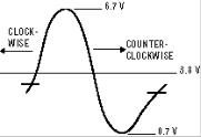
9.Turn PLL VCO coil (T151) on main board fully clockwise, and then gradually turn the coil counterclockwise until voltage is at the maximum level (approximately 6.7 VDC). Continue to turn the coil counterclockwise until the voltage is at the minimum level (approximately 0.7 VDC), and then turn the coil clockwise until voltage indicates 3.8 ± 1.0 VDC. Voltage change in the coil
adjustments is shown in Figure 6. 10. Disconnect voltmeter from chassis.
Select every active channel with keys 0 ~ 9 and the scanning keys, and check to be sure the AFT is operating properly.
Figure 6. Voltage Change in Coil Adjustment
RF-AGC ADJUSTMENT
1.Tune receiver to strongest VHF station in your area.
2.Set contrast and brightness controls for maximum.
3.Turn off the receiver and disconnect the AC power cord (120V AC line).
4.While pressing the MENU key, reconnect the AC power cord. The Service Menu display will now appear.
5.Select NO. 03 RAD (RF-AGC Delay) with ▲ or ▼ key.
6.Adjust the data with + or – key in the direction which causes snow to appear; then in the opposite direction until the snow just disappears.
7 . To turn off the Service Menu display, press the MENU key.
BRIGHTNESS LEVEL ADJUSTMENT
Note: Grayscale, RF-AGC, Video Level, and High Voltage Check must be adjusted before attempting Brightness Level Adjustment.
1.Connect a color-bar generator to the antenna terminals.
2.Switch the generator to the crosshatch pattern.
3.Reset the picture controls to the Sports levels.
4.Connect voltmeter (high impedance) + lead to terminal TP51 and – lead to terminal TP50 on main board. Set voltmeter for 1.5V ~ 3V range.
5.Turn off the receiver and disconnect the AC power cord (120V AC line).
6.While pressing the MENU key, reconnect the AC power cord. The Service Menu display will now appear.
7.Select NO. 25 SB (Sub Brightness) with ▲ or ▼ key.
8.Adjust the data with + or – key for 820mVDC.
9.Press the MENU key to turn off the Service Menu display. 10. Check brightness level on every active channel, readjust
(repeat steps 5 ~ 9) if necessary).
Note: Do not set to excessive brightness level, otherwise the contrast level will be suppressed.
HIGH VOLTAGE HOLD-DOWN TEST
Every time the receiver is serviced, the HIGH VOLTAGE HOLD-DOWN circuit must be tested for proper operation by following these steps:
1.Connect receiver to 120V AC line. Tune receiver to active channel. Reset the picture controls to the Sports levels.
2.Check that the voltage measured between TP7 and TE7 (ground side) is within 16.5 VDC to 21 VDC. If the voltage is out of this range, the Hold-Down Circuit must be checked.
3.Connect a DC Voltage supply to TP7 and TE7 through a 100 ohm 1/4W resistor. Adjust the DC voltage to 23 VDC. The receiver should shutdown, losing raster and sound. Then the receiver should turn off automatically. This reaction indicates that the Hold-Down circuit is functioning properly. If the receiver does not shutdown, a malfunction is indicated and its cause must be found and corrected.
4.To obtain picture again, remove the DC Supply and wait a few minutes. Now turn on the receiver.
HIGH VOLTAGE CHECK
Note: +B (+130V) Voltage Check and Grayscale Adjustment
must be completed before attempting High Voltage
Check.
1.Connect high voltage voltmeter negative lead to ground, and connect + lead to anode of picture tube.
2.Tune receiver to an active channel and confirm TV is operating properly.
3.Eliminate the beam current by adjusting the contrast and brightness controls to minimum.
4.Confirm high voltage is within 28.0 KV and 30.0 KV. If reading is not within range, check horizontal circuit.
No high-voltage adjustment is provided on this chassis.
SOUND ADJUSTMENT
1.Connect Voltmeter – lead to ground and + lead IC101 Pin 50 (FM DET OUT).
2.Tune receiver to an active channel.
3.Confirm D.V.M. reading of 3.85 ± 0.2 VDC.
4.If the voltage is out of this range, adjust Sound I.F. Transformer (T131) for 3.85 ± 0.2 VDC.
— 7 —

SERVICE ADJUSTMENTS (Continued)
VIDEO LEVEL
1.Turn off the receiver and disconnect the AC power cord (AC 120V line).
2.Connect oscilloscope to TP16A and ground.
3.While pressing the Menu key, reconnect the AC power cord. The Service Menu will now appear.
4.Connect color bar generator to antenna terminals.
5.Select NO. 16 VL (Video Level) with the ▲ or ▼ key.
6.Adjust the + or – key for an oscilloscope reading of 2.0 ± 0.2% VP-P at TP16A. Press the MENU key to turn off the Service Menu display.
MULTI-SOUND SECTION ADJUSTMENTS
Note: Multi-Sound Section must be adjusted after IC101 (Signal Processor), IC3401 (MTS Decoder), IC802 (EEPROM), or T131 (Sound I.F. transformer) is replaced.
INPUT LEVEL ADJUSTMENT
1.Turn off the receiver and disconnect the AC power cord (AC 120V line).
2.Connect voltmeter (RMS) to TP317 and ground.
3.While pressing the Menu key, reconnect the AC power cord. The Service Menu will now appear.
4.Select a channel with audio of 1 KHZ 100% modulation.
5.Select NO. 32 ATT (Attenuation) with the ▲ or ▼ key.
6.Adjust the + or – key for a voltmeter reading of 400 ± 5% mVrms at TP317.
SEPARATION ADJUSTMENT
7.Turn off the receiver and disconnect the AC power cord (AC 120V line).
8.Connect oscilloscope CH1 to TP317 and CH2 to TP318 and ground.
9.Connect an MTS TV/Stereo generator to antenna terminal. 10. While pressing the Menu key, reconnect the AC power
cord. The Service Menu will now appear.
11.Select pilot, 300Hz audio frequency and Left modulating signal.
12. Select NO. 35 WDB (Wideband) with the ▲ or ▼ key.
13.Adjust the + or – key for minimum low frequencies at TP317. (See Figure 8.)
14.Select 4 KHz audio frequency and Right modulating signal.
15.Select NO. 36 SPC (Spectral) with the ▲ or ▼ key.
16.Adjust the + or – key for minimum high frequencies at TP318. (See Figure 8.)
Repeat adjustments (steps 11–16) until no further decreases in amplitude can be obtained. Press the MENU key to turn off the Service Menu display.
Figure 8. Separation Adjustments
PURITY AND CONVERGENCE ADJUSTMENTS
Purity and Convergence have been aligned at the factory. No re-alignment is necessary.
— 8 —

SERVICE HINTS
POWER FAILURE DETECTOR
This unit is equipped with a Power Failure Detector function included in the CPU which checks for an abnormal condition in the chassis power supplies, including the power supply derived from the Horizontal Output Transformer.
If, while the power is on, a failure is caused by any of the following which results in a low voltage supply, the CPU will turn the unit off in 1.5 seconds to prevent unnecessary damage:
•Failure within the power supply circuits.
•A short circuit in the load side from the supply.
•Stoppage of the Horizontal Output Oscillator caused by the X-Radiation protection Hold-Down Circuit.
If, while the power is off, the power is switched on and any of these failures remains uncorrected, the CPU will shut off the power within 3 seconds.
Check the following if the unit is turned off by the power failure detector.
1.Disconnect the AC power cord (120V AC line) for at least 10 seconds.
2.Connect a DC Voltmeter to the following TEST POINTS.
TJ5 9V
TJ7 7.6V
D312 Cathode . . . .5V
D429 Cathode . . . .5V
3.Press the Power key and check for the proper voltage supplies.
4.If any of these voltages is low, the power failure detector should turn the unit off within 3 seconds.
5.Check all circuits listed above.
Note: This unit is equipped with a Power Surge Protection feature included in the CPU. If power failure occurs three times within 15 minutes, the CPU will automatically stop functioning to help prevent secondary damage. (TV will not turn on by pressing the power key.) To reset the operating programs within the CPU, disconnect the AC power cord for at least 10 seconds.
— 9 —

MECHANICAL DISASSEMBLIES
CABINET BACK REMOVAL
1.Refer to Figure 1, remove 9 screws.
2.Pull off cabinet back and remove.
Figure 1. Cabinet Back Removal
CHASSIS REMOVAL
1.Remove cabinet back.
2.Discharge the picture tube anode (2nd anode lead) to the dag coating (picture tube grounding lead).
3.Disconnect degaussing coil socket (KD), picture tube socket, deflection yoke connector (KX), speakers connector (KSP), picture tube ground lead, and 2nd anode lead.
4.Remove chassis completely by sliding it straight back.
PICTURE TUBE REMOVAL
CAUTION: Do not disturb the deflection yoke or magnet assembly on the picture tube neck. Care must be taken to keep these assemblies intact, unless picture tube is being replaced. Discharge the picture tube to the coating before handling the tube.
1.Remove chassis, referring to Chassis Removal instructions.
2.Place cabinet’s front face down on a soft surface.
3.Remove the screw on each corner of the picture tube and GENTLY lift the picture tube out of the cabinet.
4.Install a replacement picture tube in reverse order. Properly install the degaussing coil and picture tube grounding lead on the picture tube. See Figure 2.
Note: If Picture Tube is being replaced, mount the Degaussing Coil properly on the tube. See Figure 2.
Figure 2. Picture Tube Removal
— 10 —
 Loading...