


Model No:
No. de Modelo: DP42746
HIGH-DEFINITION TELEVISION
Plasma TV
Owner’s Manual
ENGLISH
Table of Contents . . . . . 3
TV de Plasma
Manual de Instrucciónes
ESPAÑOL
Contenido . . . . . . . . . . 29
™
®
ENERGY STAR
“As an ENERGY STAR® Partner, Sanyo Manufacturing Corporation has determined that this product meets the ENERGY STAR® guidelines for energy efficiency.”
© 2006 Sanyo Manufacturing Corporation
As Real As It Gets!
“Read this manual before assembling (or using) this product.”
Need assistance?
Visit our website at www.sanyoctv.com or
Call toll free 1.800.877.5032
We can Help!
Importado Por : Comercializadora México
Americana, S. DE R.L. DE C.V.
Nextengo No 78
Col. Santa Cruz Acayucan
Del. Azcapotzalco, México D.F. C.P. 02770
RFC CMA 9109119L0
Telefono: 55-5328-3500
Printed in U.S.A. SMC, March 2006 Impreso en U.S.A. SMC, Marzo 2006
Part No. / No. de Parte : 1AA6P1P5111– –
|
|
|
|
|
CAUTION |
|
THIS SYMBOL INDICATES THAT DANGEROUS VOLTAGE CONSTITUT- |
|
RISK OF ELECTRIC SHOCK DO NOT OPEN |
|
ING A RISK OF ELECTRIC SHOCK IS PRESENT WITHIN THIS UNIT. |
|
|
|
|
|
|
|
|
|
CAUTION: TO REDUCE THE RISK OF ELECTRIC SHOCK, DO NOT REMOVE COVER (OR |
|
THIS SYMBOL INDICATES THAT THERE ARE IMPORTANT OPERATING |
|
BACK). NO USER-SERVICEABLE PARTS INSIDE. REFER SERVICING TO QUALIFIED |
|
AND MAINTENANCE INSTRUCTIONS IN THE LITERATURE ACCOM- |
|
SERVICE PERSONNEL. |
|
PANYING THIS UNIT. |
|
|
|
|
WARNING: TO REDUCE THE RISK OF FIRE OR ELECTRIC SHOCK, DO NOT EXPOSE THIS APPLIANCE TO RAIN OR MOISTURE.
IMPORTANT SAFETY INSTRUCTIONS
1.Read these instructions.
2.Keep these instructions.
3.Heed all warnings.
4.Follow all instructions.
5.Do not use this apparatus near water.
6.Clean only with dry cloth.
7.Do not block any ventilation openings. Install in accordance with the manufacturer’s instructions.
8.Do not install near any heat sources such as radiators, heat registers, stoves, or other apparatus (including amplifiers) that produce heat.
9.Do not defeat the safety purpose of the polarized or grounding-type plug. A polarized plug has two blades with one wider than the other. A grounding-type plug has two blades and a third grounding prong. The wide blade or the third prong are provided for your safety. If the provided plug does not fit fully into your outlet, consult an electrician for replacement of the obsolete outlet.
10.Protect the power cord from being walked on or pinched particularly at plugs, convenience receptacles, and the point where they exit from the apparatus.
11.Only use attachments/accessories specified by the manufacturer.
12.Use only with the cart, stand, tripod,
bracket, or table specified by the manu-  facturer, or sold with the apparatus.
  When a cart is used, use caution when
  moving the cart/apparatus combination
  to avoid injury from tip-over.
13.Unplug this apparatus during lightning storms or when unused for long periods of time.
14.Refer all servicing to qualified service personnel. Servicing is required when the apparatus has been damaged in any way, such as power-supply cord or plug is damaged, liquid has been spilled or objects have fallen into the apparatus, the apparatus has been exposed to rain or moisture, does not operate normally, or has been dropped.
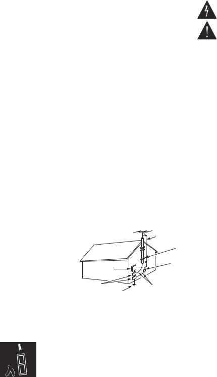
15.If an outside antenna is connected to the television equipment, be sure the antenna system is grounded so as to provide some protection against voltage surges and built up static charges. In the U.S. Selection 810-21 of the National Electrical Code provides information with respect to proper grounding of the mast and supporting structure, grounding of the leadin wire to an antenna discharge unit, size of grounding conductors, location of antenna discharge unit, connection to grounding electrodes, and requirements for the grounding electrodes.
EXAMPLE OF ANTENNA GROUNDING ACCORDING TO NATIONAL ELECTRICAL
CODE, ANSI/NFPA 70
|
ANTENNA |
|
LEAD IN |
|
WIRE |
|
GROUND |
|
CLAMP |
ELECTRIC |
ANTENNA |
SERVICE |
DISCHARGE UNIT |
EQUIPMENT |
(NEC SECTION 810-20) |
GROUND CLAMPS |
GROUNDING CONDUCTORS |
POWER SERVICE GROUNDING |
(NEC SECTION 810-21) |
ELECTRODE SYSTEM |
NEC - NATIONAL ELECTRICAL CODE |
(NEC ART 250, PART H) |
“Note to CATV system installer:
This reminder is provided to call the CATV system installer’s attention to
Article 820-40 of the NEC that provides guidelines for proper grounding and, in particular, specifies that the cable ground shall be connected to the grounding system of the building, as close to the point of cable entry as practical.”
16.An outside antenna system should not be located in the vicinity of overhead power lines or other electrical light or power circuits, or where it can fall into such power lines or circuits. When installing an outside antenna system, extreme care should be taken to keep from touching such power lines or circuits as contact with them might be fatal.
17."Apparatus shall not be exposed to dripping or splashing and no objects filled with liquids, such as vases, shall be placed on the apparatus."
2 Need help? Visit our Web site at www.sanyoctv.com or Call 1-800-877-5032

TO THE OWNER
Welcome to the World of Sanyo
Thank you for purchasing this Sanyo Plasma High-Definition television. You made an excellent choice for Performance, Reliability, Features, Value, and Styling.
Important Information
Before installing and operating this Plasma DTV, read this manual thoroughly. This Plasma DTV provides many convenient features and functions. Operating the Plasma DTV properly
enables you to manage those features and maintain it in good condition for many years to come. Improper operation may result in not only shortening the product-life, but may also cause malfunctions or other serious problems.
If your Plasma DTV seems to operate improperly, read this manual again, check operations and cable connections and try the solutions in the “Helpful Hints” section, page 26 of this manual. If the problem still persists, visit our website at www.sanyoctv.com or call 1.800.877.5032. We Can Help!
CONTENTS
Important Safety Instructions . . . . . . . . . . . . . . . . . . . . . . . 2
To The Owner . . . . . . . . . . . . . . . . . . . . . . . . . . . . . . . . . . 3
Contents . . . . . . . . . . . . . . . . . . . . . . . . . . . . . . . . . . . . . . 3
Features . . . . . . . . . . . . . . . . . . . . . . . . . . . . . . . . . . . . . . 4
Specifications . . . . . . . . . . . . . . . . . . . . . . . . . . . . . . . . . . 4
Handling Precautions . . . . . . . . . . . . . . . . . . . . . . . . . . . . . 5
Care and Cleaning . . . . . . . . . . . . . . . . . . . . . . . . . . . . . . . 5
Cleaning the Plasma DTV . . . . . . . . . . . . . . . . . . . . . . . . . . . . . . . . 5 Caring for the Plasma DTV . . . . . . . . . . . . . . . . . . . . . . . . . . . . . . . 5
Installation Precautions . . . . . . . . . . . . . . . . . . . . . . . . . . . 6
Child Safety . . . . . . . . . . . . . . . . . . . . . . . . . . . . . . . . . . . . . . . . . . 6
Positioning Precautions . . . . . . . . . . . . . . . . . . . . . . . . . . . . . . . . . 6
Removing the Plasma Stand (Feet) (Optional) . . . . . . . . . . . . . . . . 6
First-Things-First (Required Initial Setup) . . . . . . . . . . . . . . . 7
Initial Signal Connections . . . . . . . . . . . . . . . . . . . . . . . . . . . . . . . . 7
Digital RF Antenna Connection . . . . . . . . . . . . . . . . . . . . . . . . . . . 7
Analog RF Antenna Connection . . . . . . . . . . . . . . . . . . . . . . . . . . 7
Install Batteries . . . . . . . . . . . . . . . . . . . . . . . . . . . . . . . . . . . . . . . . 8
Connect AC Power Cord . . . . . . . . . . . . . . . . . . . . . . . . . . . . . . . . . 8
All Channel Search . . . . . . . . . . . . . . . . . . . . . . . . . . . . . . . . . . . . . . 8
Analog Antenna Signal Selection (Optional) . . . . . . . . . . . . . . . . . . 8
Top and Back Panels . . . . . . . . . . . . . . . . . . . . . . . . . . . . . 9
Choose Your Connection . . . . . . . . . . . . . . . . . . . . . . . . . . 10
Digital AV Connections
Connecting External Equipment to HDMI Input . . . . . . . . . . . . . . . 11
Connect STB or DVD with DVI Output to HDMI Input . . . . . . . . . . 12
Connecting Digital Audio Output to a Multi-Channel Receiver . . . . 12
Use the Component Jacks to Connect a DVD Player
or Other Digital Equipment . . . . . . . . . . . . . . . . . . . . . . . . . . . . . . 13
Analog AV INPUT Connections
Use the Video1 Jacks to Connect a VCR
or other Analog Equipment . . . . . . . . . . . . . . . . . . . . . . . . . . . . . . 14
Connecting Analog Audio Output Jacks to Stereo Amplifier . . . . . 15
Typical Home Theater Connections . . . . . . . . . . . . . . . . . . 15
Using the Remote Control . . . . . . . . . . . . . . . . . . . . . . . . . 16
Precautions . . . . . . . . . . . . . . . . . . . . . . . . . . . . . . . . . . . . . . . . . . 16
Remote Control Keys . . . . . . . . . . . . . . . . . . . . . . . . . . . . . . 16 ~ 17
TV Adjustment and Setup . . . . . . . . . . . . . . . . . . . . . . . . . 18
Basic Menu Operation . . . . . . . . . . . . . . . . . . . . . . . . . . . . . . . . . . 18
Menu Navigation Map . . . . . . . . . . . . . . . . . . . . . . . . . . . . . . . . . . 18
Menu Options:
All Channel Search . . . . . . . . . . . . . . . . . . . . . . . . . . . . . . . . . . . . . 18
Digital Cable Search (Optional) . . . . . . . . . . . . . . . . . . . . . . . . . . . 19
Digital Add-on Search . . . . . . . . . . . . . . . . . . . . . . . . . . . . . . . . . . 19
Analog Antenna Signal Selection (Optional) . . . . . . . . . . . . . . . . . 20
Channel Scan Memory . . . . . . . . . . . . . . . . . . . . . . . . . . . . . . . . . 20
Digital Caption . . . . . . . . . . . . . . . . . . . . . . . . . . . . . . . . . . . . . . . . 21
Changing the Look of Digital Captions . . . . . . . . . . . . . . . . . . . 21 To View Captions . . . . . . . . . . . . . . . . . . . . . . . . . . . . . . . . . . . . 21 V-Guide (Parental Control) . . . . . . . . . . . . . . . . . . . . . . . . . . . . . . 22 To Block MPAA Movie or TV Program . . . . . . . . . . . . . . . . . . . . 22 To Setup V-Guide Ratings . . . . . . . . . . . . . . . . . . . . . . . . . . . . . 22 Temporarily Unblock MPAA Movie or TV Program . . . . . . . . . . 23 To Unblock All MPAA Movie or All TV Ratings . . . . . . . . . . . . . . 23 MPAA Movie Ratings (Age-Based) . . . . . . . . . . . . . . . . . . . . . . . 23 TV Ratings (Age/Content-Based) . . . . . . . . . . . . . . . . . . . . . . . . 23 Picture/Sound Adjustment . . . . . . . . . . . . . . . . . . . . . . . . . . . . . . 24 Menu Language . . . . . . . . . . . . . . . . . . . . . . . . . . . . . . . . . . . . . . . 24 Picture Rotation (Screen Saver) . . . . . . . . . . . . . . . . . . . . . . . . . . 25 White Pattern Setup (Panel Repair) . . . . . . . . . . . . . . . . . . . . . . . . 25
Helpful Hints (Problems/Solutions) . . . . . . . . . . . . . . . . . . 26
Mexico Guarantee . . . . . . . . . . . . . . . . . . . . . . . . . . . . . . 27
United States and Canada Warranty . . . . . . . . . . . . . . . . . . 28
Need help? Visit our Web site at www.sanyoctv.com or Call 1-800-877-5032 |
3 |

FEATURES
42" Plasma HDTV Screen
RF Antenna Input Jacks: Digital and Analog
Built-in Digital and Analog Tuners
Receivable Formats: ATSC Digital Tuner for Terrestrial Broadcasts and non-scrambled (ClearQAM) broadcasts, NTSC Analog Tuner for VHF / UHF or CATV
Receives 181 Analog Channels (VHF 2~13 and UHF 14~69; Cable TV 1, 14~125); and 99 Digital Channels
Automatic Channel Search
Channel Scan Memory
3-D Y/C Digital Comb Filter (for better picture detail)
V-Chip for Movies and TV Guidelines Rating Limits (Parental Control)
Closed-Captioning: Analog EIA-608B and Digital EIA-708B
Audio Modes: TV—Main and Sub NTSC—Stereo, Mono, and SAP
Tone
Picture Rotation (Screen Saver)
White Pattern (Panel Repair)
Audio Format: Dolby® Digital 5.1 for TV and Analog for NTSC
Front Speakers 6 x 12 cm (two)
Detachable TV Stand (Feet)
Trilingual Menu Options
Factory Preset Adjustments for Picture / Sound
Picture Shape: PIX1, PIX2, PIX3, and PIX4
Sleep Timer (3 hours)
HDMI (High-Definition Multimedia Interface) Input with HDCP (High-bandwidth Digital Content Protection)
RF Antenna Input Jacks: Digital and Analog
Component Video Input (Two Sets)
Rear Composite AV Input
S-Video Input
Optical Digital Audio Out
Fixed Analog Audio Out
XDS (Extended Data Services) Displays Station Call Letters, Title of Show, and Ratings when Broadcast
32-Key Remote Control
SPECIFICATIONS
Screen Size: |
42 inches (Measured Diagonally) |
Panel Type: |
Plasma HDTV Display |
Aspect Ratio |
16:9 |
Display area: |
934 mm (W) x 532 mm (H) |
Resolution: |
1024 x 768 pixels |
Color System: |
ATSC / NTSC |
Scanning Format: |
720p (RF signals are converted to 720p) |
RF Antenna Input: |
Analog–UHF / VHF / CATV 75 ohm |
|
Digital–75 ohm |
Power Requirement: Source: AC 120V, 60Hz
Power Consumption: 351 Watts (Maximum)
Sound: Two Speakers, size: 6x12cm
Amplifier: Built-in with 5.0W/ch
Jacks and Connectors:
Video 1 Input: |
Composite Video and Audio L/R |
|
S-Video |
Video 2 Input: |
Component (Y/ Pb/Pr) with Audio L/R Input |
Video 3 Input: |
Component (Y/ Pb/Pr) with Audio L/R Input |
Digital Audio Output: |
Dolby® Digital (Optical) |
Analog Audio Output: |
Audio L/R |
HDMI Input: |
19-pin connector |
|
(Picture/Sound with HDCP) |
Service Input Jacks: |
For Production use only |
Size and Weight (approximately):
Horizontal Dim. (Width): |
47.5 in. (1205.8 mm) |
Vertical Dim. (Height): |
28.2 in. (715.2 mm) |
Depth Dim. (Thickness): |
9.8 in. (248.3 mm) |
Weight: |
84.1 lbs. (38.2 Kg) |
Environmental Considerations |
|
Operating Temperature: |
32°F ~ 140°F (0°C ~ 60°C) |
Humidity: |
20 ~ 80% |
Storage Temperature: |
-4°F ~ 158°F (-20°C ~ 70°C) |
Humidity: |
5 ~ 95 % |
Specifications are subject to change without notice.
CAUTION: FCC Regulations state that improper modifications or unauthorized changes to this unit may void the user’s authority to operate the unit.
Trademarks Information:
Manufactured under license from Dolby Laboratories. “Dolby” and the double-D symbol are trademarks of Dolby Laboratories.


 with a double “Z” is a registered trademark of Sanyo Manufacturing Corporation.
4 Need help? Visit our Web site at www.sanyoctv.com or Call 1-800-877-5032
HANDLING PRECAUTIONS
•Handle the Plasma DTV carefully when installing. Do Not Drop.
•Locate the set away from heat, excessive dust, and direct sunlight.
NOTE: When the Plasma DTV is not used for a long period of time, dark dots may be observed. This is a characteristic of the Plasma display. If this occurs, turn the Plasma DTV On and leave it on about one hour. These dots will gradually disappear.
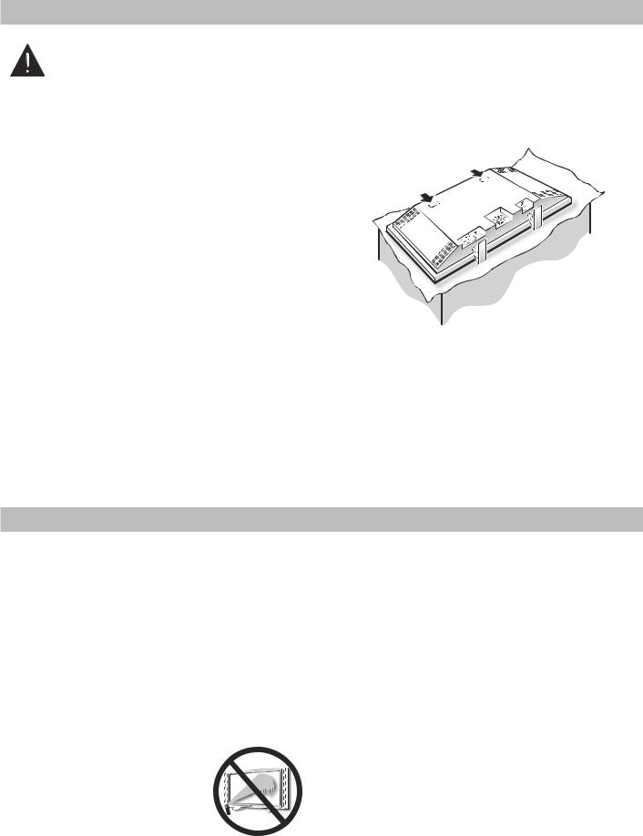
•Throughout the installation process, handling by more than two people is recommended.
•When removing the feet, use a working space that is larger than the screen size. The work surface must be flat and covered with a soft cloth or blanket to protect the screen surface.
•Before placing the Plasma DTV face down, make sure there are no objects under the screen. Leaving any object may cause damage on the screen surface.
Hand Slots
CARE AND CLEANING
CLEANING THE PLASMA DTV |
|
CARING FOR THE PLASMA DTV |
|
The surface of the cabinet can be damaged if not properly |
|
Do not bump or scratch the panel surface as this causes |
|
|
|||
maintained. Many common household aerosol sprays, |
|
flaws on the surface of the screen. |
|
cleaning agents, solvents, and polishes will cause perma- |
|
Do not display a still image on the screen for a long time. |
|
nent damage to the fine surface. |
|
||
|
Otherwise, an afterimage or “ghost” may appear on a |
||
1. Unplug the power cord before cleaning the Plasma |
|
||
|
part of the panel. To prevent this symptom, use the |
||
DTV. |
|
“Picture Rotation (Screen Saver) and White Pattern |
|
2. Gently wipe the screen and cabinet with dry soft |
|
(panel repair)” function of the Plasma DTV. See page 25. |
|
cloth. |
|
There may be some tiny black points and/or blight points |
|
The screen is likely to be damaged if it is not maintained |
|
on the Plasma Display Panel. These points are normal. |
|
properly. Do not use hard objects like a hard cloth or |
|
|
|
paper. Do not use solvents or abrasives. |
|
|
|
NOTES: Never spray liquids on the |
|
|
|
screen. |
|
|
|
Do not use benzene, thinner, or |
|
|
|
any volatile substances to clean |
|
|
|
the Plasma DTV. These chemi- |
|
|
|
cals may damage the cabinet |
|
|
|
|
|
|
|
finish. |
|
|
|
Need help? Visit our Web site at www.sanyoctv.com or Call 1-800-877-5032 |
5 |
||
INSTALLATION PRECAUTIONS
CHILD SAFETY
Sanyo is committed to making home entertainment safe and enjoyable. Always use an appropriate table or stand when positioning your DTV. Use appropriate brackets, braces, or straps to anchor your furniture in place. But never screw anything directly to the television.
Do not place televisions on dressers, shelves, desks, carts, etc. where curious or excited children could pull, push, or otherwise cause the unit to fall and cause personal injury.
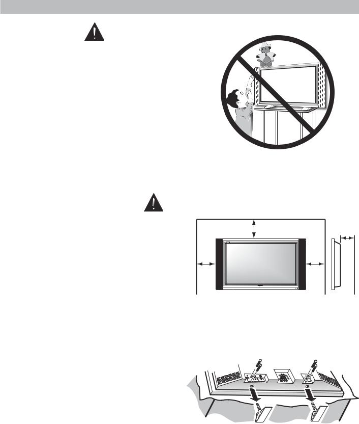
Never place toys or other items on top of the DTV that could pique children’s curiosity causing them to climb about the furniture.
Always use stands that are designed to support the size and combined weight of your television and other electronic devices.
POSITIONING PRECAUTIONS
•Place this Plasma DTV as indicated here. Failure to do so may result in a fire hazard. Allowing the proper amount of space at the top, sides, and rear of the Plasma DTV cabinet is critical for proper air circulation and cooling of the unit. The dimensions shown here indicate the minimum space required. If the Plasma DTV is to be built into a compartment or similarly enclosed, these minimum distances must be maintained.
•Do not cover the ventilation slots on the Plasma DTV. Heat build-up can reduce the life of your Plasma DTV, and can also be dangerous.
•If the Plasma DTV is not to be used for an extended period of time, unplug it from the power outlet.
|
4” (10 cm) |
2.36” |
|
(6 cm) |
|
|
|
|
4” |
|
4” |
(10 cm) |
|
(10 cm) |
|
AS |
|
REMOVING THE PLASMA STAND (FEET) (OPTIONAL)
Remove two (2) screws from each foot bracket, then slide the feet out of the brackets.
6 Need help? Visit our Web site at www.sanyoctv.com or Call 1-800-877-5032
FIRST-THINGS-FIRST (Required Initial Setup)
This Plasma television will reproduce a crystal clear Digital picture and exceptional sound.
The signal makes the difference!
1INITIAL SIGNAL CONNECTIONS
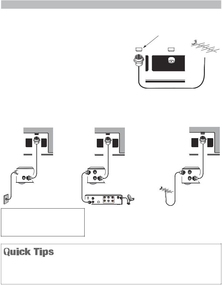
Digital (DTV) RF Antenna Connection
•Connect an RF Antenna to the Digital Antenna In terminal.
The digital tuner in this DTV receives HD signals from an antenna. Digital signals from a Set-top Box (STB) are received through the Component In jacks.
This DTV can receive ANY resolution being broadcast (HDTV, EDTV, or SDTV). However, ALL resolutions are converted to 1080i for display.
|
|
DIGITAL ANTENNA INPUT |
|
DIGITAL RF |
||||||
|
|
|
|
|
|
|
|
ANTENNA |
||
|
|
|
|
|
|
|
|
|
|
|
|
|
|
|
|
|
|
|
|
|
|
|
|
|
|
|
|
|
|
|
|
|
|
|
|
|
|
|
|
|
|
|
|
|
|
|
|
|
|
|
|
|
|
|
|
|
|
|
|
|
|
|
|
|
|
|
|
|
|
|
|
|
|
|
|
|
D |
L |
|
NTENNA IN |
UHF/VHF/CATV |
|
PLASMA TV BACK
Analog RF Antenna Connection
•Connect a Cable signal (with or without a cable box), Satellite Receiver, or RF antenna to the Analog RF input.
The analog tuner in this Plasma DTV receives Analog Antenna signals, Analog Cable signals, or the RF output from a Satellite Receiver, VCR, or cable box.
PLASMA |
|
PLASMA |
|
DTV BACK |
|
DTV BACK |
|
UHF/VHF/CATV |
UHF/VHF/CATV |
PLASMA |
UHF/VHF/CATV |
|
|
DTV BACK |
|
OR OR

 IN
IN 
FROM ANT.
OUT |
VCR BACK |
OUT TO TV |
IN |
VCR BACK |
IN |
VCR BACK |
FROM ANT. |
FROM ANT. |
||
OUT |
|
OUT |
|
OUT TO TV |
|
OUT TO TV |
|
|
ANALOG SATELLITE RECEIVER |
ANALOG RF |
|||
|
CATV IN |
|
|
|
|
ANALOG CABLE |
CH3 |
|
|
|
ANTENNA |
CH4 |
VIDEO |
L- AUDIO-R |
IN FROM |
||
|
|||||
|
OUT TO TV |
S-VIDEO |
|
SAT. |
|
|
|
VIDEO |
L- AUDIO-R |
|
|
CATV FRANCHISE NOTE: Cable companies, like public utilities, are franchised by local government authorities. To receive cable programs, even with equipment which is capable of receiving cable channels, the consumer must subscribe to the cable company’s service.
Notes: If you do not have a VCR, connect signal directly to the TV 75 ohm terminal (UHF/VHF/CATV).
Don’t be fooled by the phrase “Available in HighDefinition.” The only resolution available with any of these analog connections, regardless of the original content, is standard analog (SDTV).
■DTV will select the correct Antenna mode for the type of Analog RF signal connected automatically.
■Use “Analog Antenna Signal” in the Setup menu to change the Antenna Mode.
■If you move the DTV to a new location, press the RESET key twice after connecting the signal and turning on the DTV.
(Continued on next page.)
Need help? Visit our Web site at www.sanyoctv.com or Call 1-800-877-5032 |
7 |

FIRST-THINGS-FIRST (Required Initial Setup)
2INSTALL BATTERIES
•Install two “AAA” Batteries (not included) so that the “+” and “–” marks on the batteries match the “+” and “–” marks inside the Remote.
To review the remote control functions, go to pages 16 ~17.
NOTE: Use two “AAA” Alkaline batteries.
IMPORTANT NOTE: Spent or discharged batteries must be recycled or disposed of properly in compliance with all applicable laws. For detailed information, contact your local County Solid Waste Authority.
3CONNECT AC POWER CORD
•Connect AC Power Cord (supplied) to the Plasma TV and electrical outlet as shown here.
The AC outlet must be near this equipment and must be easily accessible.
To POWER CORD
CONNECTOR on back of Plasma TV.
To 120 V AC outlet.
4ALL CHANNEL SEARCH
When the television is powered on for the
time, it automatically checks for the presence |
|
|
|
|
|
|
|
|
INPUT |
|
|
|
|
|
|
|
|
|||||||
|
|
|
|
|
|
|
|
1 |
|
|
|
|
|
2 |
|
|
|
|
|
|||||
|
|
|
|
|
|
|
|
|
|
|
|
|
|
|
|
|
|
|
POWER |
|
|
|||
an RF signal. |
|
|
|
|
|
|
|
|
|
|
|
|
|
|
|
|
|
|
|
|
|
|
3 |
|
|
|
|
|
|
|
|
|
|
|
|
|
|
|
|
|
|
|
|
|
|
|
|||
|
|
|
7 |
4 |
|
|
|
|
|
|
|
|
|
6 |
|
|||||||||
|
|
|
|
|
|
|
|
|
|
|
|
|
|
|
|
|
|
5 |
|
|
|
|
|
|
|
|
|
|
|
|
|
|
|
|
|
|
|
|
|
|
|
8 |
|
|
|
9 |
|
|
|
• Press the POWER key to turn on the |
|
|
|
|
INFO |
|
|
|
|
|
|
|
|
|
|
|
||||||||
|
|
|
|
|
|
|
|
|
|
U |
|
|
|
MUTE |
|
|
||||||||
|
|
|
|
|
|
|
|
|
|
NER |
|
|
|
|
||||||||||
|
|
|
|
|
|
|
|
|
|
|
|
|
|
|
|
0 |
|
|
|
SL |
EEP |
|
|
|
|
|
|
|
|
|
|
RECALL |
|
|
|
|
|
|
|
|
|
|
|
|
|
|
|||
DTV. |
|
|
|
|
|
|
|
|
|
|
|
|
T |
|
|
|
|
|
|
|
|
|
|
|
|
|
|
|
|
|
|
|
|
|
|
|
|
|
|
|
|
|
|
|
|
|
|
||
|
|
|
MENU |
|
|
|
|
|
|
|
|
|
|
|
|
|
||||||||
|
|
|
|
|
|
|
|
|
|
|
|
|
|
|
|
|
|
|
|
|
|
|
|
|
|
|
|
|
|
|
|
|
|
|
|
|
|
|
|
|
|
|
|
ENTER |
|
|
|
|
|
• Then |
press |
the |
CHANNEL UP |
|
|
|
|
|
|
|
|
|
|
|
|
|
|
|
|
|
|
|
|
|
(CH ▲) key to |
automatically |
|
CAPTION |
|
|
|
|
|
|
|
|
|
|
|
|
|
|
|||||||
|
|
|
|
|
|
|
|
|
|
|
|
|
|
|
|
|
|
|
|
|
|
|
||
|
|
|
|
|
|
|
|
|
|
|
|
|
|
EXIT |
|
|
|
|
|
|
||||
search |
for |
available channels: |
CH |
|
|
VOL |
|
|
|
|
|
|
||||||||||||
|
|
|
|
|
|
|
|
|
|
|
|
|
|
|
|
|
|
|
|
|
|
|
|
|
Digital (ATSC) and Analog (NTSC).
The All Channel Search contains two processes that are executed simultaneously for digital and analog channels.
NOTES: Channel information found during All Channel Search is stored in two Channel Scan Memory databases (Analog and Digital). After all channel search is completed, the TV will tune to the lowest Digital channel or lowest Analog channel if no digital channels are found.
If the TV does not detect any digital or analog channels, a message advising the viewer to check the cables and antenna connections will appear. In this case, you must press the CHANNEL UP key again to repeat the channel search process. If after two searches the TV still fails to detect any channels, the TV will tune to analog channel 3.
If no analog or digital channels are found after the second search, All Channel Search will default to offair analog channels 2 through 69 and digital channel D3-1. Select analog channels using the remote control keypad. See page 16, item number 2.


SKIP THE CHANNEL SEARCH PROCESS
Use this feature only if the DTV is used primarily for playing video games, or watching videos, or if you receive local channels from a satellite receiver or cable system.
•Press the EXIT key to cancel the channel search process.
•The DTV will be tuned to Analog Channel 3.
•Press the INPUT key (remote control) to select AV signal source connected to: Video 1, Video 2, Video 3, or HDMI jacks.
5ANTENNA SIGNAL SELECTION
(OPTIONAL)
To change the initial analog tuning system setup (from antenna to cable or cable to antenna), use the onscreen menu. See “Analog Antenna Signal” on page 20.
8 Need help? Visit our Web site at www.sanyoctv.com or Call 1-800-877-5032

TOP AND BACK PANELS
|
|
|
|
|
11 |
|
|
|
|
Power key |
Volume |
|
|
|
|
Channel |
|
|
|
|
|
– + keys |
|
|
|
|
|
▼▲ keys |
|
|
|
|
|
|
|
|
|
|
|
CH |
VOL |
BACK PANEL—BOTTOM VIEW (CENTER) |
Top Panel View (see items 8, 11, & 17 on page 17.) |
|
HDMI (High Definition Multimedia Interface) Input, PAGES 11 ~ 12—Connect digital video equipment to this jack. It takes only one high bandwidth cable (not supplied) to communicate between the video/audio equipment and this TV. This connection is compatible with DVI equipped devices. (Separate audio connection and an adapter are required for DVI device.)
Digital Audio Output, PAGE 12—Use an Optical Audio cable to connect Digital Audio Output to an advanced stereo home theater system equipped with Dolby® Digital 5.1.
Digital Antenna Input, PAGE 7—Connect an RF antenna to this jack.
Service Jacks—For production use only
Analog Antenna Input (UHF/VHF/CATV), PAGE 7—Connect an RF antenna or Analog cable system to this jack.
S-Video Input (VIDEO1), PAGE 14—To enhance video detail use the S-Video jacks instead of the Video jacks, if available on your external equipment. (S-Video connection will override connection to the
Video input jack [VIDEO1]).
Analog Audio Out (L/R) Jacks, PAGE 15—Connect external audio equipment here.
Audio/Video Input (VIDEO1), PAGE 14—Connect analog video equipment here.
NOTE: S-Video connection overrides the (Video1) composite video connection.
Component Video Input (VIDEO2), PAGE 13—
Connect digital video equipment to the Y, Pb, Pr and Audio L/ R jacks. These jacks will automatically detect the type of signal being received.
Component Video Input (VIDEO3), PAGE 13—
Connect digital video equipment to the Y, Pb, Pr and Audio L/R jacks. These jacks will automatically detect the type of signal being received.
11 AC IN 120V—Connect power cord here. See page 8.
Need help? Visit our Web site at www.sanyoctv.com or Call 1-800-877-5032 |
9 |
 Loading...