


Model Nos.:
Nos. de Modelo:
HIGH-DEFINITION TELEVISION
DP26746
DP32746
Wide Screen LCD HDTV
See What You’ve Been Missing!
Owner’s Manual
Manual Del Propietario
ENGLISH
Table of Contents . . . . . . . . . 3
ESPAÑOL
Contenido . . . . . . . . . . . . . . 33
“Read this manual before assembling (or using) this product.”
Need assistance?
Visit our Web site at
www.sanyoctv.com
or call toll free 1-800-877-5032
We can Help!
© 2006 Sanyo Manufacturing Corporation
™
Importado Por :
Comercializadora México
Americana, S. DE R.L. DE C.V.
Nextengo Nº 78
Col. Santa Cruz Acayucan
Del. Azcapotzalco, México D.F. C.P.
02770, RFC CMA 9109119L0
Telefono: 55-5328-3500
DP32746
DP26746
ENERGY STAR
“As an ENERGY STAR® Partner, Sanyo Manufacturing Corporation has determined that this product meets the ENERGY STAR® guidelines for energy efficiency.”
Printed in U.S.A. SMC, March 2006 Impreso en U.S.A. SMC, Marzo 2006 Part No. / No. de Parte :
1AA6P1P5066– –
|
|
|
|
|
CAUTION |
|
THIS SYMBOL INDICATES THAT DANGEROUS VOLTAGE CONSTITUTING A |
|
|
|
|
|
|
|
RISK OF ELECTRIC SHOCK IS PRESENT WITHIN THIS UNIT. |
|
RISK OF ELECTRIC SHOCK DO NOT OPEN |
||
|
|
|
|
|
|
|
|
CAUTION: TO REDUCE THE RISK OF ELECTRIC SHOCK, DO NOT REMOVE COVER (OR |
|
THIS SYMBOL INDICATES THAT THERE ARE IMPORTANT OPERATING AND |
|
BACK). NO USER-SERVICEABLE PARTS INSIDE. REFER SERVICING TO QUALIFIED |
|
MAINTENANCE INSTRUCTIONS IN THE LITERATURE ACCOMPANYING THIS |
|
SERVICE PERSONNEL. |
|
UNIT. |
|
WARNING: TO REDUCE THE RISK OF FIRE OR ELECTRIC SHOCK, DO NOT EXPOSE THIS APPLIANCE TO RAIN OR MOISTURE.
IMPORTANT SAFETY INSTRUCTIONS
Important Safety Instructions for LCD DTV
1.Read these instructions.
2.Keep these instructions.
3.Heed all warnings.
4.Follow all instructions.
5.Do not use this apparatus near water.
6.Clean only with dry cloth.
7.Do not block any ventilation openings. Install in accordance with the manufacturer’s instructions.
8.Do not install near any heat sources such as radiators, heat registers, stoves, or other apparatus (including amplifiers) that produce heat.
9.Do not defeat the safety purpose of the polarized or grounding-type plug. A polarized plug has two blades with one wider than the other. A grounding-type plug has two blades and a third grounding prong. The wide blade or the third prong are provided for your safety. If the provided plug does not fit fully into your outlet, consult an electrician for replacement of the obsolete outlet.
10.Protect the power cord from being walked on or pinched particularly at plugs, convenience receptacles, and the point where they exit from the apparatus.
11.Only use attachments/accessories specified by the manufacturer.
12. Use only with the cart, stand, tripod, bracket, or table specified by the manufacturer, or sold with the apparatus. When a cart is used, use caution when moving the cart/apparatus combination to avoid injury from tip-over.
13.Unplug this apparatus during lightning storms or when unused for long periods of time.
14.Refer all servicing to qualified service personnel. Servicing is required when the apparatus has been damaged in any way, such as power-supply cord or plug is damaged, liquid has been spilled or objects have fallen into the apparatus, the apparatus has been exposed to rain or moisture, does not operate normally, or has been dropped.
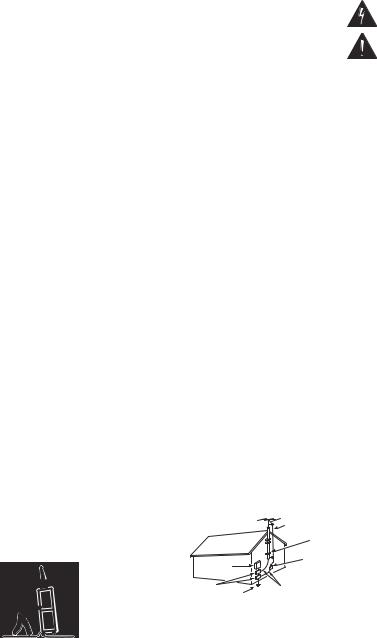
15.If an outside antenna is connected to the television equipment, be sure the antenna system is grounded so as to provide some protection against voltage surges and built up static charges. In the U.S. Selection 810-21 of the National Electrical Code provides information with respect to proper grounding of the mast and supporting structure, grounding of the lead-in wire to an antenna discharge unit, size of grounding conductors, location of antenna discharge unit, connection to grounding electrodes, and requirements for the grounding electrodes.
16.An outside antenna system should not be located in the vicinity of overhead power lines or other electrical light or power circuits, or where it can fall into such power lines or circuits. When installing an outside antenna system, extreme care should be taken to keep from touching such power lines or circuits as contact with them might be fatal.
EXAMPLE OF ANTENNA |
|
ANTENNA |
|
GROUNDING ACCORDING |
|||
LEAD IN |
|||
TO NATIONAL |
|
WIRE |
|
|
GROUND |
||
ELECTRICAL CODE, |
|
CLAMP |
|
ANSI/NFPA 70 |
ELECTRIC |
ANTENNA |
|
|
SERVICE |
DISCHARGE UNIT |
|
|
EQUIPMENT |
(NEC SECTION 810-20) |
|
GROUND CLAMPS |
GROUNDING CONDUCTORS |
||
POWER SERVICE GROUNDING |
(NEC SECTION 810-21) |
||
ELECTRODE SYSTEM |
NEC - NATIONAL ELECTRICAL CODE |
||
(NEC ART 250, PART H) |
|||
“Note to CATV system installer:
This reminder is provided to call the CATV system installer’s attention to Article 82040 of the NEC that provides guidelines for proper grounding and, in particular, specifies that the cable ground shall be connected to the grounding system of the building, as close to the point of cable entry as practical.”
17."Apparatus shall not be exposed to dripping or splashing and no objects filled with liquids, such as vases, shall be placed on the apparatus."
2 |
Need help? Visit our Web site at www.sanyoctv.com or Call 1-800-877-5032 |

Welcome to the World of Sanyo
Thank you for purchasing this Sanyo LCD HighDefinition Digital Television. You made an excellent choice for Performance, Reliability, Features, Value, and Styling.
Important Information
Before installing and operating this DTV, read this manual thoroughly. This DTV provides many convenient features and functions. Operating the DTV
properly enables you to manage those features and maintain it in good condition for many years to come.
If your DTV seems to operate improperly, read this manual again, check operations and cable connections and try the solutions in the “Helpful Hints” section, pages 28 ~ 29 of this manual. If the problem still persists, visit our website at www.sanyoctv.com or call 1.800.877.5032. We can help!
CONTENTS
Important Safety Instructions . . . . . . . . . . . . . . . . . . 2 Content . . . . . . . . . . . . . . . . . . . . . . . . . . . . . . . . . 3 Features . . . . . . . . . . . . . . . . . . . . . . . . . . . . . . . . 4 Specifications . . . . . . . . . . . . . . . . . . . . . . . . . . . . 4 Getting Started (Required Initial Setup) . . . . . . . . 5 ~ 8
Positioning the LCD DTV . . . . . . . . . . . . . . . . . . . . . . 5 Wall Mounting (Optional) . . . . . . . . . . . . . . . . . . . . . . 5 Detaching the DTV Stand (Optional) . . . . . . . . . . . . . 5 Installing Batteries in the Remote Control . . . . . . . . . 6 Initial Signal Connections . . . . . . . . . . . . . . . . . . . . . . 6
Digital (DTV) RF Antenna Connection . . . . . . . . . . 6 Analog RF Antenna Connection . . . . . . . . . . . . . . . 7 All Channel Search . . . . . . . . . . . . . . . . . . . . . . . . . . . 8 Analog Antenna signal (optional) . . . . . . . . . . . . . . . . 8
Side and Back Panels . . . . . . . . . . . . . . . . . . |
. . . . 9 |
Choose Your Connection . . . . . . . . . . . . . . . . . |
. . . 10 |
Digital AV Connections . . . . . . . . . . . . . . . . . . |
11 ~ 16 |
Connecting External Equipment to HDMI . . . . . . . . . 11 Connecting STB with DVI Output to HDMI . . . . . . . . 12 Using the Component Jacks to connect
a DVD Player or other digital equipment . . . . . . . . . 13 Connecting Digital Audio Out jack to a
Multi-Channel Receiver . . . . . . . . . . . . . . . . . . . . . . 14
Analog AV Connections . . . . . . . . . . . . . . . . . |
15 ~ 16 |
Using the Analog Video jacks to connect
a VCR (or other analog device) . . . . . . . . . . . . . . . . 15 Connecting Analog Audio Out jacks to
a Stereo Amplifier . . . . . . . . . . . . . . . . . . . . . . . . . . 16
Using the Remote Control . . . . . . . . . . . . . . . . 17 ~ 19
DTV Adjustment and Setup . . . . . . . . . . . . . . . 20 ~ 27
How to Operate the On-Screen Menu . . . . . . . . . . . 20 Menu Navigation Map . . . . . . . . . . . . . . . . . . . . . . . 20 Menu Options:
All Channel Search . . . . . . . . . . . . . . . . . . . . . . . . . . 20 Digital Cable Search (Optional) . . . . . . . . . . . . . . . . 21 Digital Add-On Search . . . . . . . . . . . . . . . . . . . . . . . 22 Analog Antenna Signal (Optional) . . . . . . . . . . . . . . 22 Channel Scan Memory . . . . . . . . . . . . . . . . . . . . . . . 23 Digital Caption . . . . . . . . . . . . . . . . . . . . . . . . . . . . . 24
Changing the Look of Digital Captions . . . . . . . . . 24 To View Captions . . . . . . . . . . . . . . . . . . . . . . . . . 24 V-Guide (Parental Control) . . . . . . . . . . . . . . . . 25 ~ 26 To Block MPAA Movie or TV Programs . . . . . . . . 25 To Setup V-Guide Ratings . . . . . . . . . . . . . . . . . . . 25
To Temporarily Unblock MPAA Movie
or TV Program . . . . . . . . . . . . . . . . . . . . . . . . . . . 26 To Unblock All MPAA Movie or All TV Ratings . . . 26
MPAA Movie Ratings (Age-Based) Symbol
Explanation . . . . . . . . . . . . . . . . . . . . . . . . . . . . . . 26
DTV Ratings (Age and Content-Based)
Symbol Explanation . . . . . . . . . . . . . . . . . . . . . . . . 26 Picture/Sound Adjustment . . . . . . . . . . . . . . . . . . . . 27 Menu Language . . . . . . . . . . . . . . . . . . . . . . . . . . . . 27
Helpful Hints (Problems / Solutions) . . . . . . . . 28 ~ 29 Care and Cleaning . . . . . . . . . . . . . . . . . . . . . . . . 29 Mexico Guarantee . . . . . . . . . . . . . . . . . . . . . . . . 30 Warranty (U.S.A. and Canada) . . . . . . . . . . . . . . . . 31 Child Safety Matters . . . . . . . . . . . . Inside Back cover
Need help? Visit our Web site at www.sanyoctv.com or Call 1-800-877-5032 |
3 |

FEATURES
DP26746: 26” / DP32746: 32” Wide Screen LCD HDTV
Detachable DTV Stand
Side bar Controls
3-Line Digital Comb Filter
Built-in Digital and Analog Tuners
Trilingual Menu options (English, Spanish, or French)
V-Chip for Movies and TV guidelines rating limits
Closed-Captioning: Analog EIA 608B / Digital EIA-708B
Audio Modes: Digital—Main and Sub
Analog—Stereo, Mono, and SAP
Tone
Front speakers (two): 6 x 12 cm
Factory preset adjustments for picture/sound
Picture Shape: PIX1, PIX2, PIX3, and PIX4
Automatic Channel Search
Audio Format: Dolby® digital 5.1 for DTV / Analog for NTSC
Receivable Formats: Digital Tuner for ATSC terrestrial broadcasts and nonscrambled (ClearQAM) cable channels. NTSC analog tuner for VHF/UHF or CATV
Channel Scan Memory
Receives 181 Analog Channels (VHF 2~13 and
UHF 14~69; Cable 14~125); and 99 Digital Channels
HDMI (High-Definition Multimedia Interface) Input with HDCP (High-bandwidth Digital Content Protection)
RF Antenna Input Jacks: Digital and Analog
Component Video Input (Two Sets)
Rear Composite AV Input
S-Video Input
Optical Digital Audio Out
Fixed Analog Audio Out
XDS (Extended Data Services) displays station call letters, title of show, and ratings when broadcast
Sleep Timer (3 hours)
32-Key Remote Control
CAUTION: FCC Regulations state that improper modifications or unauthorized changes to this unit may void the user’s authority to operate the unit.
SPECIFICATIONS
LCD Panel Size (Measured Diagonally):
DP26746: 26-inches / DP32746: 32-inches
1366 x 768 (WXGA)
720p (RF Signals are Converted to 720p)
Jacks and Connectors: |
|
Video 1 Input: |
Video and Audio L/R Composite |
|
S-Video |
Video 2 Input: |
Component (Y/ Pb/Pr) with |
|
Audio L/R Input |
Video 3 Input: |
Component (Y/ Pb/Pr) with |
|
Audio L/R Input |
Digital Audio Output: |
Dolby® Digital (Optical) |
Analog Audio Output: |
Audio L/R (Fixed) |
HDMI Input: |
19-pin connector |
|
(Picture/Sound with HDCP) |
Sound: |
Two Speakers, size: 6 x 12 cm |
Amplifier: |
Built-in with 3.0W/ch |
Power Requirement: |
Source: AC 120V, 60Hz |
AC Power Consumption (average): DP26746: 135 watts DP32746: 155 watts
Size and Weight (approximately):
DP26746 |
|
Horizontal Dim. (Width) |
26.7 in. (678mm) |
Vertical Dim. (Height) |
21.1 in. (537mm) |
Depth Dim. (Thickness) |
7.9 in. (201mm) |
Weight |
26.4 (lbs) 12.0 (Kg) |
DP32746 |
|
Horizontal Dim. (Width) |
32.0 in. (812mm) |
Vertical Dim. (Height) |
24.2 in. (614mm) |
Depth Dim. (Thickness) |
7.9 in. (201mm) |
Weight |
33.0 (lbs) 15.0 (Kg) |
Specifications are subject to change without notice.
Trademarks Information:
Manufactured under license from Dolby Laboratories “Dolby” and the double-D symbol are trademarks of Dolby Laboratories.


 with a double “Z” is a registered trademark of Sanyo Manufacturing Corporation.
4 |
Need help? Visit our Web site at www.sanyoctv.com or Call 1-800-877-5032 |
GETTING STARTED
POSITIONING THE LCD DTV
Always use an appropriate table or stand when positioning your DTV. For best viewing, avoid locating the DTV where direct sunlight or indoor lighting will fall on the screen. Do not position the DTV in a confined area. Allow adequate space for proper ventilation.
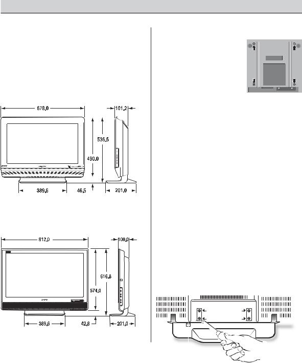
Model DP26746
NOTE: All dimensions are in millimeters (mm).
Model DP32746
WALL MOUNTING (OPTIONAL)
This LCD DTV is designed so that it may be mounted on a wall, if desired. Use the threaded inserts on the back of your DTV to secure it using a wall mounting kit.
NOTE: Wall |
Mounting |
kit is |
|
not |
supplied, |
check |
DTV Back View |
with |
your local |
elec- |
|
tronics store.
LCD Mounting screws measurements:
DP26746—M4 Diameter, Length—10mm
(minimum) to 20mm (maximum).
DP32746—M6 Diameter, Length—10mm
(minimum) to 20mm (maximum).
DETACHING THE DTV STAND (OPTIONAL)
Tools Needed: Phillips screwdriver
Important Note: Place DTV face down on a padded or cushioned surface to protect the screen and finish.
1 Removebracket. four (4) screws from the metal CAUTION: Hold the stand firmly as you remove the last screw.
2 Carefully remove the DTV stand.
|
|
|
|
|
|
|
|
|
|
|
|
|
|
|
|
|
|
|
|
|
|
|
|
|
|
|
|
|
|
|
|
|
|
|
|
Need help? Visit our Web site at www.sanyoctv.com or Call 1-800-877-5032 |
5 |
||||||||||
GETTING STARTED (REQUIRED INITIAL SETUP)
INSTALLING BATTERIES IN THE REMOTE CONTROL
Use 2 “AAA” batteries (Not supplied).
Be sure batteries are installed correctly. Match the “+” and “–” signs on the batteries with marks inside the remote control.
NOTES:
–Do not mix old batteries with new
ones or mix different types of batteries together.
– Remove the batteries if the remote control will not be used for a month or more. Weak batteries may leak and cause damage. (Normal battery life is roughly six months.) 
– Use two “AAA” Alkaline batteries.
IMPORTANT NOTE: Spent or discharged batteries must be recycled or disposed properly in compliance with all applicable laws. For detailed information, contact your local County Solid Waste Authority.
This LCD HDTV is capable of reproducing a crystal clear digital picture and exceptional sound. The signal makes the difference!
INITIAL SIGNAL CONNECTIONS
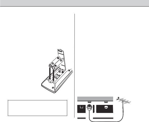
1 DIGITAL (DTV) RF ANTENNA CONNECTION
•Connect an RF antenna to the Digital Antenna In terminal.
The digital tuner in this DTV receives HD signals from an antenna. Digital signals from a Set-top Box (STB) are received through the Component In jacks.
This DTV can receive ANY resolution being broadcast (HDTV, EDTV, or SDTV).
DTV Back
AUDIO |
ANTENNA IN |
UHF/VHF/CATV |
RF Antenna |
DIGITAL |
DIGITAL |
|
|
|
|
|
|
OUTPUT |
|
|
|
Operational Tip for Monitor Use: |
|
If the DTV is used as a monitor only, with a DVD |
After the initial channel search is completed, you |
player or some other type of external equipment, |
must press the Channel (CH) ▲ key again to |
and no cable or antenna signal is available, the |
complete the channel search process. This may |
following setup is necessary: |
take several minutes. |
Your DTV is designed to automatically search for |
After the channel search process is complete (2 |
available channels. Therefore, the initial start up |
searches), you can press the INPUT key on the |
requires that you press the Channel (CH) ▲ key, |
remote control to use the DTV as a monitor. |
enabling the DTV to automatically go through the |
|
channel search process before you can operate |
|
the DTV. |
|
|
|
6 |
Need help? Visit our Web site at www.sanyoctv.com or Call 1-800-877-5032 |
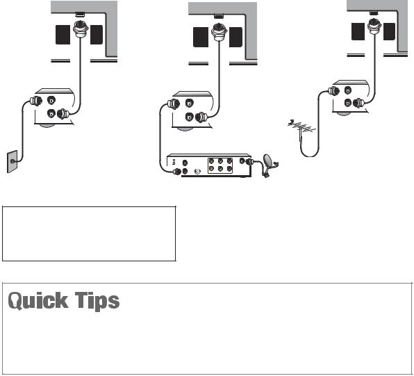
2 ANALOG RF ANTENNA CONNECTION
•Connect a Cable signal (with or without a cable box) or RF antenna to the Analog RF input.
The analog tuner in this DTV receives Analog Antenna signals, Analog Cable signals, or the RF output from a VCR or cable box.
DTV Back |
DTV Back |
DTV Back |
|
UHF/VHF/CATV |
|
UHF/VHF/CATV |
|
UHF/VHF/CATV |
OR |
||
|
|||
|
OR |
||
VCR Back |
|
VCR Back |
|
VCR Back |
|
||
|
IN |
||
|
|
||
IN |
|
FROM ANT. |
|
IN |
OUT |
||
FROM ANT. |
|||
FROM ANT. |
OUT TO TV |
||
OUT |
|||
OUT |
|
||
OUT TO TV |
|
||
OUT TO TV |
|
||
|
|
RF
Antenna
CATV IN |
|
|
|
CH3 |
|
|
|
CH4 |
VIDEO |
L- AUDIO-R |
IN FROM |
|
|||
OUT TO TV |
S-VIDEO |
|
SAT. |
|
VIDEO |
L- AUDIO-R |
|
Analog Cable
Analog Satellite Receiver
CATV FRANCHISE NOTE: Cable companies, like public utilities, are franchised by local government authorities. To receive cable programs, even with equipment which is capable of receiving cable channels, the consumer must subscribe to the cable company’s service.
NOTES: If you do not have a VCR, connect signal directly to the 75 ohm terminal (UHF/ VHF/CATV).
Don’t be fooled by the phrase “Available in High-Definition.” The only resolution available with any of these connections, regardless of the original content, is standard analog (SDTV).
■DTV will select the correct Antenna mode for the type of Analog RF signal connected automatically.
■Use “Analog Antenna Signal” in the Setup menu to change the Antenna Mode.
■If you move the DTV to a new location, press the RESET key twice after connecting the signal and turning on the DTV.
(Continued on page 8.)
Need help? Visit our Web site at www.sanyoctv.com or Call 1-800-877-5032 |
7 |
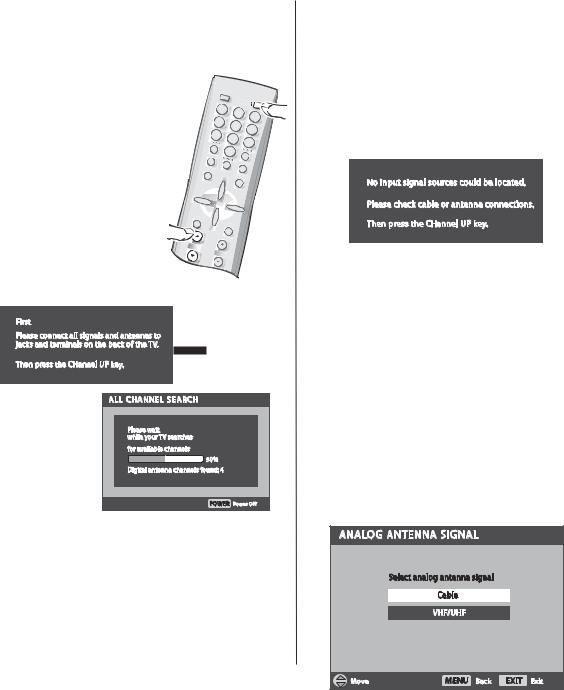
3 ALL CHANNEL SEARCH
When the television is powered on for the first time, it automatically checks for the presence of an RF signal.
• Press the Power key to turn on the DTV.
• Then press the Channel Up (CH ▲) key to automatically search for available channels: Digital (ATSC) and Analog (NTSC).
The All |
Channel Search |
|
contains |
two processes |
CH |
that are executed simultaneously for digital and analog channels.
NOTES:
The on-screen message for digital search will appear with a progress bar and percentile number displayed across the bottom of the screen (to indicate activity) as the search process continues.
Channel information found during the All Channel Search is stored in Analog and Digital Channel Scan Memory databases. After the All Channel Search is completed, the DTV will tune to the lowest Digital channel or lowest Analog channel if no digital channels are found.
If the DTV does not detect any digital or analog channels, a message advising the viewer to check the cables and antenna connections will appear. In this case, you must press the CHANNEL UP (CH ▲) key again to repeat the channel search process. If after two searches the DTV still fails to detect any channels, the DTV will tune to analog channel 3.
These two channel searches are necessary even if you plan to use the DTV only as a monitor.
If no analog or digital channels are found after the second search, All Channel Search will default to off-air analog channels 2 through 69 and digital channel D3-1. Select analog channels using the remote control keypad. See page 17, item number 2.
4 ANALOG ANTENNA SIGNAL
(OPTIONAL)
To change the initial analog tuning system setup (from antenna to cable or cable to antenna), use the on-screen menu, see “Analog Antenna Signal” on page 22.
8 |
Need help? Visit our Web site at www.sanyoctv.com or Call 1-800-877-5032 |
|
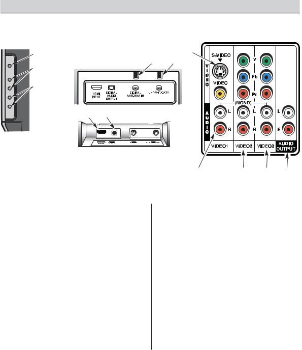
SIDE AND BACK PANELS |
|||
Right Side Panel |
|
|
Back Panel (Right) |
|
(see items 8, 11, & 17 |
|
|
||
on pages 18 & 19) |
|
|
|
|
|
Power |
|
|
|
|
key |
|
|
|
|
Back Panel (Center) |
|||
POWER |
Volume |
|
|
|
|
– + keys |
|
|
|
|
Channel |
|
|
|
|
▼▲ keys |
|
|
|
|
|
|
|
|
|
Back Panel—Bottom View (Center) |
|
||
HDMI (High Definition Multimedia Interface) Input, PAGES 11 and 12—Connect digital video equipment to this jack. It takes only one high bandwidth cable (not supplied) to communicate between audio/ video equipment and this DTV. This connection is compatible with DVI equipped AV devices. (Separate audio connection and an adapter are required for DVI device.)
Digital Audio Output, PAGE 14—Use an Optical Audio cable to connect Digital Audio Output to an advanced stereo home theater system equipped with Dolby® Digital 5.1.
Digital Antenna Input, PAGE 5—Connect an RF antenna to this jack.
Analog Antenna Input (UHF/VHF/CATV), PAGE 5—Connect an RF antenna or Analog cable system to this jack.
S-Video Input (VIDEO1), PAGE 15—To enhance video detail use the S-Video jacks instead of the Video jacks, if available on your external equipment. (S-Video connection will override connection to the Video input jack [VIDEO1]).
Audio/Video Input (VIDEO1), PAGE 15—
Connect analog video equipment here.
NOTE: S-Video connection overrides the (VIDEO1) composite video connection.
Component Video Input (VIDEO2), PAGE 13—Connect digital video equipment to the
Y, Pb, Pr and Audio L / R jacks. These jacks will automatically detect the type of signal being received.
Component Video Input (VIDEO3), PAGE 13—Connect digital video equipment to the Y, Pb, Pr and Audio L / R jacks. These jacks will automatically detect the type of signal being received.
Analog Audio Out (L/R) Jacks, PAGE 16—
Connect external audio equipment here.
Need help? Visit our Web site at www.sanyoctv.com or Call 1-800-877-5032 |
9 |

CHOOSE YOUR CONNECTION
This DTV is designed to handle several different connections making it compatible with Digital and Analog devices.
In order to receive the best performance from your DTV, choose your connection using this chart; then go to the specified page for detailed instructions.
Digital Signal |
Compatible External |
Cables Needed |
Go to |
|
Connections |
Equipment |
|
(Not Supplied) |
Page |
HDMI |
Digital Set-Top Box |
Video Game |
19 Pin HDMI |
11 |
Will accept HDTV |
or DVD Player |
|
|
|
|
|
OR |
||
(High Bandwidth |
|
|
|
|
|
|
|
12 |
|
Video component |
|
|
|
|
|
|
|
|
|
and Audio 5.1) |
|
|
|
|
COMPONENT |
Video Game |
|
Component |
13 |
(Y, Pb, Pr) IN |
|
|
Video |
|
Will accept HDTV, |
|
|
Cable |
|
|
|
[Green, Blue, |
|
|
EDTV, or SDTV |
|
Digital Set-Top Box or |
|
|
|
and, Red |
|
||
Video content. |
|
DVD Player |
|
|
|
connectors] |
|
||
(Requires separate |
|
|
|
|
|
|
Audio Cable |
|
|
audio connections.) |
|
|
|
|
|
|
|
[White and Red |
|
|
|
|
connectors] |
|
DIGITAL AUDIO OUT |
|
|
Optical Digital |
14 |
(Only available when |
|
|
Cable |
|
received as part of a |
Multi-Channel |
|
|
|
Digital RF signal or |
|
|
|
|
HDMI signal.) |
Receiver |
|
|
|
Analog Signal |
Compatible External |
Cables Needed |
Go to |
|
Connections |
Equipment |
|
(Not Supplied) |
Page |
COMPOSITE VIDEO |
Video Game |
|
Composite |
15 |
OR |
|
|
Video Cable |
|
S-VIDEO IN |
|
DVD Player |
[Yellow, White, |
|
|
and Red |
|
||
LEFT / RIGHT |
|
|
|
|
|
|
connectors] |
|
|
ANALOG AUDIO IN |
|
VCR |
S-Video |
|
|
|
Cable |
|
|
ANALOG AUDIO |
|
|
Audio Cable |
16 |
|
|
[White and Red |
||
OUT JACKS |
|
|
||
|
|
connectors] |
|
|
|
|
|
|
|
|
Stereo Amplifier System |
|
|
|
10 Need help? Visit our Web site at www.sanyoctv.com or Call 1-800-877-5032 |
|
|||
DIGITAL AV CONNECTIONS
This is the best option for picture and sound! Using the HDMI connection, which has high-definition content protection, provides you with uncompressed digital video and audio, Dolby® Digital 5.1 or PCM sound. This connection requires only one cable. As Real As It Gets!
CONNECTING EXTERNAL EQUIPMENT TO HDMI (INCLUDES HDCP COPY PROTECTION)
To avoid problems with some brands of external equipment, follow this procedure when connecting cables and powering on your equipment.
1 Switch off DTV and external equipment before connecting cable. (Cable is not supplied.)
2 Connect the external equipment’s high bandwidth HDMI Output to the DTV’s HDMI Input.
3 The DTV must be turned on first, press POWER. Then turn on your external equipment.
4 Press INPUT to select HDMI to view a digital program.
■If the television HDMI pin configuration is different from the pin configuration on your set-top box, you will need to use an Adapter.
■Press the INPUT key after connecting cables to access the AV Inputs. There is NO need to tune to a blank channel.
SET-TOP BOX (Can be a Digital Satellite Receiver, DVD Player, or similar digital device.)
HDMI CABLE
(Gently insert |
2 |
cable into |
DTV HDMI
Input jack.)
|
|
|
|
|
|
|
|
BACK VIEW |
REMOTE CONTROL |
OF DTV |
|
|
||
4 


3
What you will need for connections:
19 Pin HDMI Digital Cable – 1
(Make sure you check the pin configuration of the cable plug-end*)
*Adapter may be required. Check with your local electronics store.
IMPORTANT NOTE FOR MONITOR USE:
If you did not connect an antenna, you must run All Channel Search twice before you can select the AV inputs.
Need help? Visit our Web site at www.sanyoctv.com or Call 1-800-877-5032 |
11 |
 Loading...