


DP32649

© 2009 Sanyo Manufacturing Corporation
31.5”
Model No.: / No. de Modelo: / Nº de modèle :
DP32649
Table of ContentsOwner’s ManualOwner’s Manual
Tabla de contenidoManual del usuarioManual del usuario
Table des matières
4
22
22
4040Manuel d’instructionsManuel d’instructions
Part No. / No. de parte / de piece : 1JC6P1P0333- -1JC6P1P0333- -
HDTV LCD
TVHD de LCD
TVHD ACL
2
Need help? www.sanyoctv.com 1-800-877-5032
1. Read these instructions.
2. Keep these instructions.
3. Heed all warnings.
4. Follow all instructions.
5. Do not use this apparatus near water.
6. Clean only with dry cloth.
7. Do not block any ventilation openings. Install in
accordance with the manufacturer’s instructions.
8. Do not install near any heat sources such as radiators,
heat registers, stoves, or other apparatus (including
amplifiers) that produce heat.
9. Do not defeat the safety purpose of the polarized or
grounding-type plug. A polarized plug has two blades with
one wider than the other. A grounding-type plug has two
blades and a third grounding prong. The wide blade or the
third prong are provided for your safety. If the provided
plug does not fit fully into your outlet, consult an electrician for replacement of the obsolete outlet.
10. Protect the power cord from being walked on or
pinched particularly at plugs, convenience receptacles,
and the point where they exit from the apparatus.
11. Only use attachments/accessories specified by the
manufacturer.
12. Use only with the cart, stand, tripod,
bracket, or table specified by the manufacturer, or sold with the apparatus.
When a cart is used, use caution when
moving the cart/apparatus combination
to avoid injury from tip-over.
13. Unplug this apparatus during lightning storms or when
unused for long periods of time.
14. Refer all servicing to qualified service personnel.
Servicing is required when the apparatus has been
damaged in any way, such as power-supply cord or
plug is damaged, liquid has been spilled or objects have
fallen into the apparatus, the apparatus has been
exposed to rain or moisture, does not operate normally,
or has been dropped.
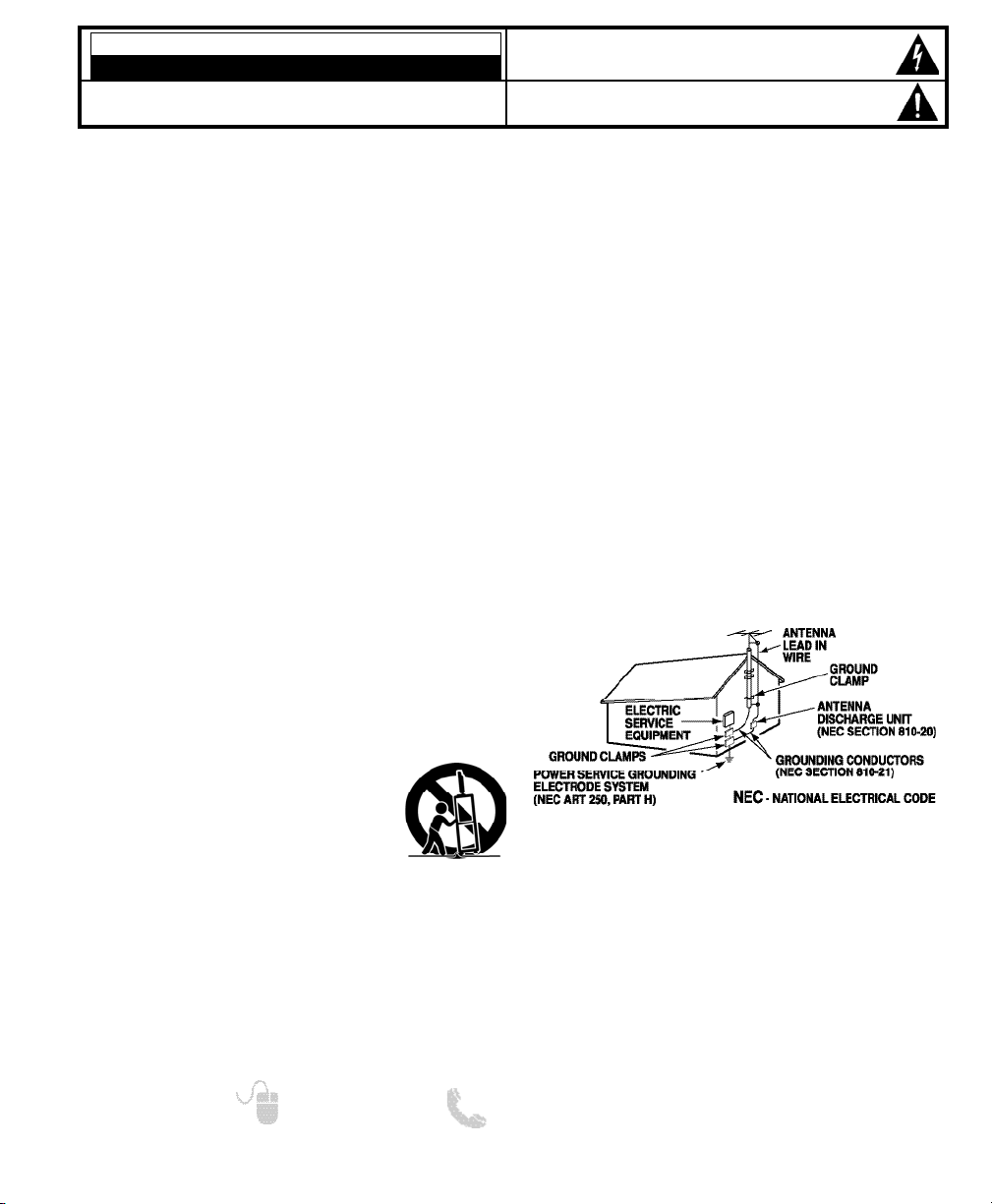
15. If an outside antenna is connected to the television
equipment, be sure the antenna system is grounded so
as to provide some protection against voltage surges
and built up static charges. In the U.S. Selection 810-21
of the National Electrical Code provides information with
respect to proper grounding of the mast and supporting
structure, grounding of the lead-in wire to an antenna
discharge unit, size of grounding conductors, location of
antenna discharge unit, connection to grounding electrodes, and requirements for the grounding electrodes.
16. An outside antenna system should not be located in the
vicinity of overhead power lines or other electrical light
or power circuits, or where it can fall into such power
lines or circuits. When installing an outside antenna
system, extreme care should be taken to keep from
touching such power lines or circuits as contact with
them might be fatal.
EXAMPLE OF ANTENNA GROUNDING ACCORDING
TO NATIONAL ELECTRICAL CODE, ANSI/NFPA 70
“Note to CATV system installer:
This reminder is provided to call the CATV system installer’s
attention to Article 820-40 of the NEC that provides guidelines for
proper grounding and, in particular, specifies that the cable
ground shall be connected to the grounding system of the building, as close to the point of cable entry as practical.”
17. Wall or Ceiling Mounting—The product should be
mounted to a wall or ceiling only as recommended by
the manufacturer.
18. Apparatus shall not be exposed to dripping or splashing
and no objects filled with liquids, such as vases, shall be
placed on the apparatus.
19. When the MAINS plug is used as the disconnect device,
the disconnect device shall remain readily operable.
CAUTION
RISK OF ELECTRIC SHOCK DO NOT OPEN!
CAUTION: TO REDUCE THE RISK OF ELECTRIC SHOCK, DO NOT REMOVE COVER (OR
BACK). NO USER-SERVICEABLE PARTS INSIDE. REFER SERVICING TO QUALIFIED SERVICE PERSONNEL.
THIS SYMBOL INDICATES THAT DANGEROUS VOLTAGE CONSTITUTING A
RISK OF ELECTRIC SHOCK IS PRESENT WITHIN THIS UNIT.
THIS SYMBOL INDICATES THAT THERE ARE IMPORTANT OPERATING AND
MAINTENANCE INSTRUCTIONS IN THE LITERATURE ACCOMPANYING THIS
UNIT.
WARNING: TO REDUCE THE RISK OF FIRE OR ELECTRIC SHOCK, DO NOT EXPOSE THIS APPLIANCE TO
RAIN OR MOISTURE.
IMPORTANT SAFETY INSTRUCTIONS
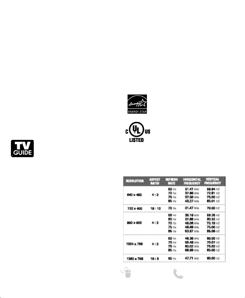
PC RESOLUTION CHART
“As an Energy Star® Partner, Sanyo
Manufacturing Corporation has determined that this product meets the Energy
Star® guidelines for energy efficiency.”
This symbol on the nameplate means
the product is Listed by Underwriter’s
Laboratories Inc. It is designed and
manufactured to meet rigid U.L. safety
standards against risk of fire, casualty
and electrical hazards.
3
Need help? www.sanyoctv.com 1-800-877-5032
FCC INFORMATION
This equipment has been tested and found to comply with the limits for a Class B digital device, pursuant to Part 15
of the FCC Rules. These limits are designed to provide reasonable protection against harmful interference in a residential installation. This equipment generates, uses and can radiate radio frequency energy and, if not installed and
used in accordance with the instructions, may cause harmful interference to radio communications. However, there
is no guarantee that interference will not occur in a particular installation. If this equipment does cause harmful
interference to radio or television reception, which can be determined by turning the equipment off and on, the user
is encouraged to try to correct the interference by one or more of the following measures:
– Reorient or relocate the receiving antenna.
– Increase the separation between the equipment and receiver.
– Connect the equipment into an outlet on a circuit different from that to which the receiver is connected.
– Consult the dealer or an experienced radio/TV technician for help.
CAUTION: FCC Regulations state that improper modifications or unauthorized changes to this unit may void
the user’s authority to operate the unit.
TRADEMARKS
Manufactured under license from Dolby Laboratories.
“Dolby” is a trademark of Dolby Laboratories.
In the United States, TV Guide and other
related marks are trademarks of GemstarTV Guide International, Inc. and/or its sub-
sidiaries. In Canada, TV Guide is a registered mark of Transcontinental Inc., and is used under
license by Gemstar-TV Guide International, Inc. and/or its
subsidiaries.
The TV Guide On Screen
TM
system is manufactured
under license from Gemstar-TV Guide International, Inc.
and/or its subsidiaries.
The TV Guide On Screen system is protected by one or
more of the following United States patents 6,498,895;
6,396,546; 5,940,073; 6,239,794 to Gemstar-TV Guide
International, Inc. and/or its subsidiaries.
Gemstar-TV Guide International, Inc. and/or its related
affiliates are not in any way liable for the accuracy or
availability of the program schedule information or other
data in the TV Guide On Screen system and cannot guarantee service availability in your area. In no event shall
Gemstar-TV Guide International, Inc. and/or its related
affiliates be liable for any damages in connection with the
accuracy or availability of the program schedule information or other data in the TV Guide On Screen system.
HDMI, the HDMI Logo and High-Definition Multimedia
Interface are trademarks or registered trademarks of
HDMI Licensing LLC.
This Class B digital apparatus complies with Canadian
ICES-003.
4
Need help? www.sanyoctv.com 1-800-877-5032
CONTENTS
IMPORTANT SAFETY INSTRUCTIONS . . . . . . . . . . . . . . . 2
FCC INFORMATION . . . . . . . . . . . . . . . . . . . . . . . . . . . . . . . .3
TRADEMARKS . . . . . . . . . . . . . . . . . . . . . . . . . . . . . . . . . . . .3
THINK GAIA . . . . . . . . . . . . . . . . . . . . . . . . . . . . . . . . . . . . . .3
DISPOSAL PRECAUTIONS . . . . . . . . . . . . . . . . . . . . . . . . . . .3
PC RESOLUTIONS . . . . . . . . . . . . . . . . . . . . . . . . . . . . . . . . . .3
CONTENTS . . . . . . . . . . . . . . . . . . . . . . . . . . . . . . . . . . . . . . .4
SPECIFICATIONS . . . . . . . . . . . . . . . . . . . . . . . . . . . . . . . . . .4
HANDLING PRECAUTIONS . . . . . . . . . . . . . . . . . . . . . . . . .4
STAND REMOVAL / WALL MOUNTING . . . . . . . . . . . . . . .5
PROTECTING THE LCD SCREEN . . . . . . . . . . . . . . . . . . . . .5
GETTING STARTED—
Remote Control Battery Installation . . . . . . . . . . . . . . . .5
Antenna Connections for off-air or cable . . . . . . . . . . .5
Remote Control operation . . . . . . . . . . . . . . . . . . . . . . . .6
PC CONNECTIONS . . . . . . . . . . . . . . . . . . . . . . . . . . . . . . . . .7
PC MENU OPERATION . . . . . . . . . . . . . . . . . . . . . . . . . . . . .7
BACK PANEL JACKS . . . . . . . . . . . . . . . . . . . . . . . . . . . . . . .8
A/V CONNECTIONS . . . . . . . . . . . . . . . . . . . . . . . . . . . . . . . .9
POWER CONNECTION / INITIAL CHANNEL SEARCH . .10
ON-SCREEN MENU OPERATION—
Channel Setting . . . . . . . . . . . . . . . . . . . . . . . . . . . . . . . .11
Channel Search . . . . . . . . . . . . . . . . . . . . . . . . . . . . .11
Channel Scan Memory . . . . . . . . . . . . . . . . . . . . . . .11
Setup . . . . . . . . . . . . . . . . . . . . . . . . . . . . . . . . . . . . . . . . .12
Menu Language . . . . . . . . . . . . . . . . . . . . . . . . . . . . .12
Digital Caption . . . . . . . . . . . . . . . . . . . . . . . . . . . . . .12
V-Chip . . . . . . . . . . . . . . . . . . . . . . . . . . . . . . . . . . . . . .13
Energy Saver . . . . . . . . . . . . . . . . . . . . . . . . . . . . . . . .14
Clock Timer . . . . . . . . . . . . . . . . . . . . . . . . . . . . . . . . .14
Picture . . . . . . . . . . . . . . . . . . . . . . . . . . . . . . . . . . . . . . . .15
Manual Picture Settings . . . . . . . . . . . . . . . . . . . . . .15
Sound . . . . . . . . . . . . . . . . . . . . . . . . . . . . . . . . . . . . . . . . .16
aaManual Sound Settings . . . . . . . . . . . . . . . . . . . . . . .16
PHOTO VIEWER . . . . . . . . . . . . . . . . . . . . . . . . . . . . . . . . . .17
TV GUIDE OPERATION . . . . . . . . . . . . . . . . . . . . . . . . . . . .18
WARRANTY . . . . . . . . . . . . . . . . . . . . . . . . . . . . . . . . . . . . . .19
CONTAINS MERCURY LAMPS,
DISPOSE OF PROPERLY
SANYO recommends keeping the TV set at its factory settings or moving Energy Saver settings
from “Level 1” to “Level 2” or “Level 3” to further
reduce power requirements and increase energy
savings. Doing so contributes to the sustainability
of our resources and environment.
For more information visit www.energystar.gov
SPECIFICATIONS
Power Requirement:
Source: AC 120V, 60Hz
AC Power Consumption: 108 watts
Dimensions:
MODEL WIDTH HEIGHT DEPTH
DP32649 31.3 22.1 8.9
w/o stand 20.8 4.7
NOTE: Dimensions are in inches
HANDLING PRECAUTIONS
• Handle by the cabinet only. Never touch the
screen when handling.
• Excessive pressure on the screen can cause per-
manent discoloration or dark spots.
• Handling damage is not covered under warranty.
POSITIONING THE LCD HDTV
Always use a firm-flat surface when positioning your HDTV. Do not position the unit
in a confined area. Allow adequate space
for proper ventilation.
5
Need help? www.sanyoctv.com 1-800-877-5032
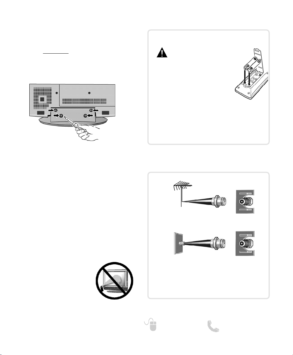
STAND REMOVAL AND WALL
MOUNTING
(OPTIONAL)
Tools Needed: Phillips screwdriver
IMPORTANT NOTE:
Place HDTV face down
on a padded or cushioned
flat surface to protect the screen and finish.
Wall mounting of the HDTV must be performed
by a skilled person.
1
Remove the four (4) screws securing the foot
stand. CAUTION: Hold the stand firmly as you
remove the last screw.
2
Use the screws you removed when detaching the stand to secure the HDTV to a wall
mounting kit (not included.)
VESA standard interface: 200 x 200
Mounting screws measurements:
M6 (6mm) Diameter, Length—16mm (maximum)
PROTECTING THE LCD SCREEN
The screen can be damaged if it is not maintained
properly. Do not use hard objects such as hard
cloth or paper. Do not use excessive pressure when
cleaning the screen; excessive
pressure can cause permanent
discoloration or dark spots.
NEVER spray liquids on the
screen.
The tuner in this HDTV can receive:
• Digital and Analog off air signals from an antenna
• Analog or ClearQAM cable channels from a direct
Cable TV connection.
GETTING STARTED
Install batteries in the remote control
( 2 “AAA”, not included)
PRECAUTIONS
To ensure safe operation, please observe
the following precautions:
• Replace both batteries at the same
time. Do not use a new battery with
a used battery.
• There’s a risk of explosion if a battery
is replaced by an incorrect type.
• Do not expose the Remote Control unit to moisture
or heat.
• Be sure to match the “+” and “
–” signs on the
batteries with marks inside the remote control.
ANTENNA CONNECTION FOR
OFF-AIR SIGNALS OR CABLE
ANTENNA
CABLE
ANALOG / DIGITAL
ANTENNA IN
BATTERY INSTALLATION
6
Need help? www.sanyoctv.com 1-800-877-5032
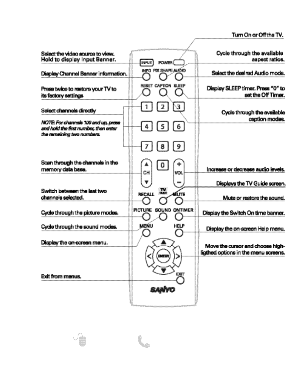
REMOTE CONTROL OPERATION
Point towards
HDTV
NOTE: For full function descriptions please see On-Screen
Menu Operation instructions starting on pg. 11.
7
Need help? www.sanyoctv.com 1-800-877-5032
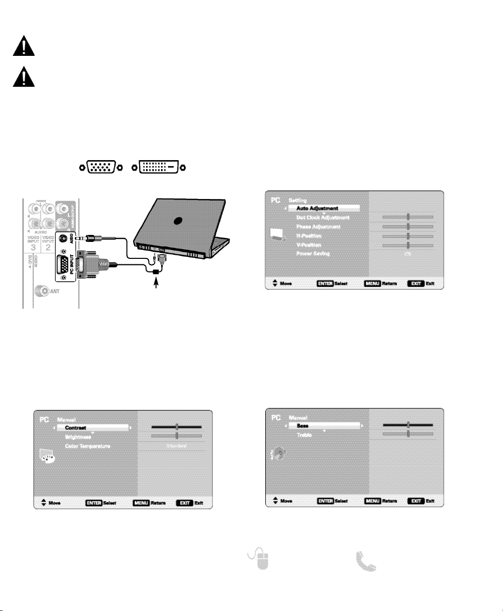
PC CONNECTIONS AND SETUP
PC PICTURE (MANUAL) SCREEN
PC SOUND (MANUAL) SCREEN
PC SETTING SCREEN
PC Setting
Auto Adjustment – Automatically adjust display
position, dot clock and phase.
Dot Clock – Adjust the Dot frequency to match
your computer’s Dot frequency.
Phase – Adjust this parameter when the picture
appears to flicker or is blurred.
H-Position – Move the image horizontally
V-Position – Move the image vertically
Power Saving – Enable the HDTV to turn to
Standby Mode when computer is not in use.
PC Picture
Standard – Sets predetermined values to the
Picture parameters.
Manual – Adjust the screen’s Contrast, Brightness
and Color Temperature settings.
NOTE: These settings do not affect normal TV viewing.
PC Sound
Standard – Sets predetermined values to the
Sound parameters.
Manual – Adjust the HDTV’s Bass and Treble
settings.
NOTE: These settings do not affect normal TV viewing.
NOTE: Before connecting any cables, disconnect the
AC power cords of both the HDTV and PC from the
AC outlets.
NOTE: Power on the HDTV and any other peripheral
equipment before powering on the computer.
To avoid an “Out of Range” condition please set
your PC’s output resolution to one compatible with
your HDTV. See page 3.
PC OR LAPTOP
HDTV BACK
RGB Monitor
cable
Stereo mini
audio cable
NOTE:If computer has only DVI Output, a DVI to RGB
converter will be required (not included.)
DVI OUTPUT
JACK
RGB OUTPUT
JACK
Sanyo recommends using a
monitor cable that includes a
Ferrite Core.
8
Need help? www.sanyoctv.com 1-800-877-5032
1
2
3
4
5
7
8
9
6
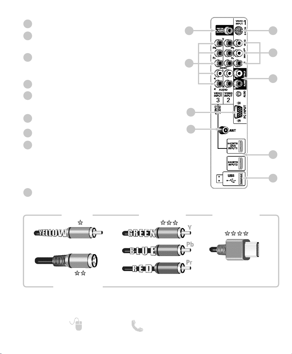
Digital Audio Output (Coaxial)
Component Video Input (VIDEO2 or VIDEO3)
Green (Y), blue (Pb), and red (Pr) Video inputs plus the
white and red Audio inputs.
PC Input and Stereo Audio (Mini)
• MONITOR RGB (D-SUB)
• AUDIO R/L (Stereo Mini Jack)
Analog / Digital Antenna Input
S-Video Input (VIDEO1)
NOTE: An S-Video connection will override a connection to
the Video1 (yellow) input jack.
AV Input (VIDEO1 - Composite)
Yellow (Video), plus white and red (Audio) input jacks.
Stereo Audio Out (L/R) Jacks
HDMI (INPUT1 or INPUT2)
An all digital AV interface that accepts uncompressed video signals for the very best picture
possible.
NOTE: A DVI conection is possible via the HDMI (DVI)
INPUT1 using an appropriate adapter and connecting the audio to the VIDEO3 Audio jacks.
USB Input
View pictures stored in a USB device.
1
2
3
4
5
6
7
8
9
BACK PANEL JACKS
Composite
S-Video
Component
H D M I
NOTE: Composite, S-Video, and Component video connections need their appropriate white and
red audio connections. High Definition image available from HD signals and HD equipment.
Above Standard
Standard High Definition
Optimum
High Definition
9
Need help? www.sanyoctv.com 1-800-877-5032
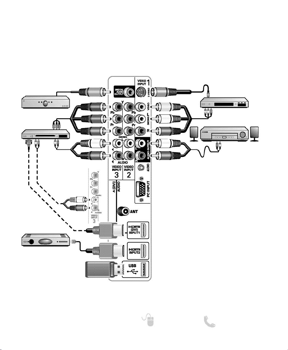
AUDIO / VIDEO CONNECTIONS
DVD PLAYER
(or similar device)
VCR
(or analog device)
STEREO
AMPLIFIER
MULTICHANNEL
RECEIVER
NOTE: Audio/Video cables are not supplied
Composite connections are used to hookup
your analog equipment such as a VCR or an
older DVD player.
S-Video connection can replace the yellow
Video connection for enhanced video.
Digital Audio Output is used to hookup a multichannel receiver with the use of a phono-type
digital audio cable.
Component connections will accept SDTV,
EDTV and HDTV video signals. Use them for
great image quality from digital devices.
SATELLITE RECEIVER
(or similar device)
USB DEVICE
Audio Output L/R are used to hookup an
external stereo Amplifier. (Do not connect
external speakers directly to the HDTV.)
HDMI INPUT1 & 2 are used to hookup HD
digital devices such as a Blu-ray player, HD
Cable Box, HD Satellite Receiver or Videogame System.
HDMI (DVI) INPUT1 can be used to hookup
a DVI device with the use of an appropriate
adapter. (VIDEO3 Audio in L/R jacks need to
be hooked up to the DVI device as well.)
USB input jack is used
to connect a USB mass
storage device to watch
JPEG images.
DVI
10
Need help? www.sanyoctv.com 1-800-877-5032
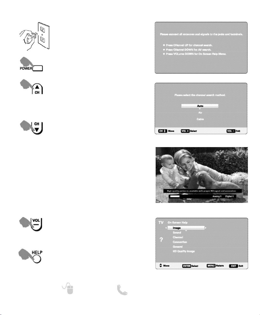
GETTING STARTED— INITIAL CHANNEL SEARCH (FIRST POWER ON)
Turn On TV
Wait for on-screen instructions to perform an Initial Channel Search.
CHANNEL SEARCH
Checks Antenna and Cable signals connected to the Antenna terminal.
AV SEARCH
Searches for signals from devices connected to the AV input jacks.
NOTE: Power ON external devices connected to the TV before
comencing an AV Search.
An AV search will begin if no Antenna signals are
detected, if neither of these searches detect signals,
the HDTV will tune to input Video1.
Plug in AC power cord
120V AC, 60Hz
Access an on screen trouble shooting
guide (in the Initial Setup Screen.)
INITIAL SETUP SCREEN
CHANNEL SEARCH METHOD SCREEN
CHANNEL SEARCH PROGRESS SCREEN
NOTE: “Auto” detects the mode detection, Cable or Air, first,
and then proceeds with the channel search.
You may acces the On Screen Help
menu later on at any time via the main
menu or by pressing the HELP key on
your remote control.
ON SCREEN HELP MENU
11
Need help? www.sanyoctv.com 1-800-877-5032
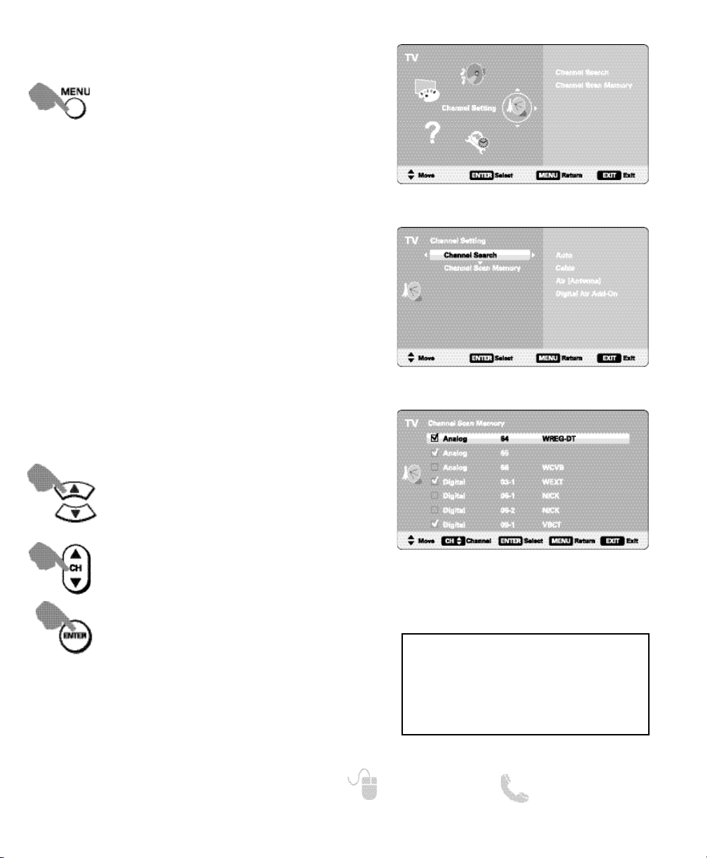
CHANNEL SETTING
Auto – Searches the detected mode, Cable or Air.
Cable – Searches for analog and unscrambled
(ClearQAM) digital cable channels.
Air (Antenna) – Searches for analog and digital off-air
channels.
Digital Air Add-On – Searches digital off-air channels
adding newly found digital channels to the channel
map database.
CHANNEL SETTING SCREEN
MAIN MENU SCREEN
CHANNEL SEARCH
Display the On Screen menu and use the
CURSOR keys to select Channel
Setting. Press ENTER.
NOTE: Digital Air Add-On option is not available when the
current mode is Cable.
ON-SCREEN MENU OPERATION
Channel Scan Memory lists all Analog and Digital
channels found. It also lists Analog channels that were
not found, which can be added.
CHANNEL SCAN MEMORY
CHANNEL SCAN MEMORY SCREEN
Move the channel select bar through all
channels, enabled and disabled.
Move the channel select bar through
enabled channels, skipping all disabled
channels.
Enable a disabled channel or disable an
enabled one.
NOTE: For information on local digital channels,
visit www.antennaweb.org
IMPORTANT FACT: This HDTV maintains only
one database of digital channels. Therefore,
when you search for cable channels, the database of antenna digital channels will be deleted.
You will only be able to receive those ClearQAM
channels your cable company provides.

12
Need help? www.sanyoctv.com 1-800-877-5032
SETUP
Display the On Screen menu and use the
CURSOR keys to select Setup.
Press ENTER.
ON-SCREEN MENU OPERATION
Choose between English, Spanish and French for your
On Screen menu’s display language.
Press ENTER on the desired language.
MENU LANGUAGE
MAIN MENU SCREEN
SETUP MENU SCREEN
Captioning is textual information transmitted along
with the picture and sound. Turning Captioning ON
causes the HDTV to open these captions (digital or analog) and superimpose them on the screen.
Digital Caption’s Font, Background and Foreground
display may be customized:
DIGITAL CAPTION
DIGITAL CAPTION SCREENS
Navigate the cursor
(highlight.)
Select / set parameter.
NOTE: Local broadcasters decide which caption signals
to transmit.
A blue marker indicates the current
selected option.
13
Need help? www.sanyoctv.com 1-800-877-5032
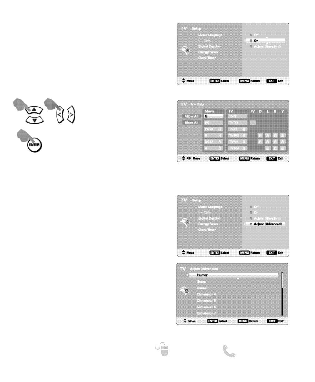
SETUP (CONTINUED)
ON-SCREEN MENU OPERATION
Use this feature to automatically block programs with
content you deem as inappropriate for viewing by
your children.
V – CHIP
SETUP V-CHIP SCREEN
ADJUST (STANDARD) SCREEN
Navigate the cursor
(highlight.)
Make selection.
Block or unblock the selected
Rating option.
NOTE: Blocking a rating will block all higher ratings automa-
tically. Unblocking a rating unblocks all lower ratings
automatically.
ADJUST (ADVANCED) SCREENS
Advanced V-Chip System
This feature is an advanced Regional rating system for
digital channels.
When the HDTV detects compatible Rating Region
Table (RRT) data, it’s downloaded & stored in memory.
The Setup V-Chip screen is then modified to show the
Adjust (Advanced) option.
Use the CURSOR and
< > keys to highlight the
different options. Use the ENTER key to block or
unblock the selected rating.
NOTE: This feature is designed to comply with the United
States of America’s FCC V-Chip regulations. Therefore,
it may not function with broadcasts that originate in
other countries.
MORE INFORMATION
Additional information about MPAA (Motion Picture
Association of America) and V-Chip rating can be
found at: www.mpaa.org and www.v-chip.org,
respectively.

14
Need help? www.sanyoctv.com 1-800-877-5032
SETUP (CONTINUED)
ENERGY SAVER SCREEN
Energy saver settings control the LCD backlight brightness to reduce power consumption.
The higher the level number, the more brightness
reduction and higher power saving.
Press ENTER on the desired level.
ENERGY SAVER
LLEEVVEELL 11 LLEEVVEELL 22 LLEEVVEELL 33
Set a Switch on Time to use with the On Timer
Function.
When On Timer Function is set to ON, the TV will auto-
matically turn on at the previously set time.
CLOCK TIMER
SWITCH ON TIME SCREEN
ON TIMER FUNCTION SCREEN
Change the value of the current
selection.
Move to the next or previous value
that you wish to change.
Save the desired Switch On Time.
Set the On Timer Function ON or
OFF.
ON-SCREEN MENU OPERATION
15
Need help? www.sanyoctv.com 1-800-877-5032
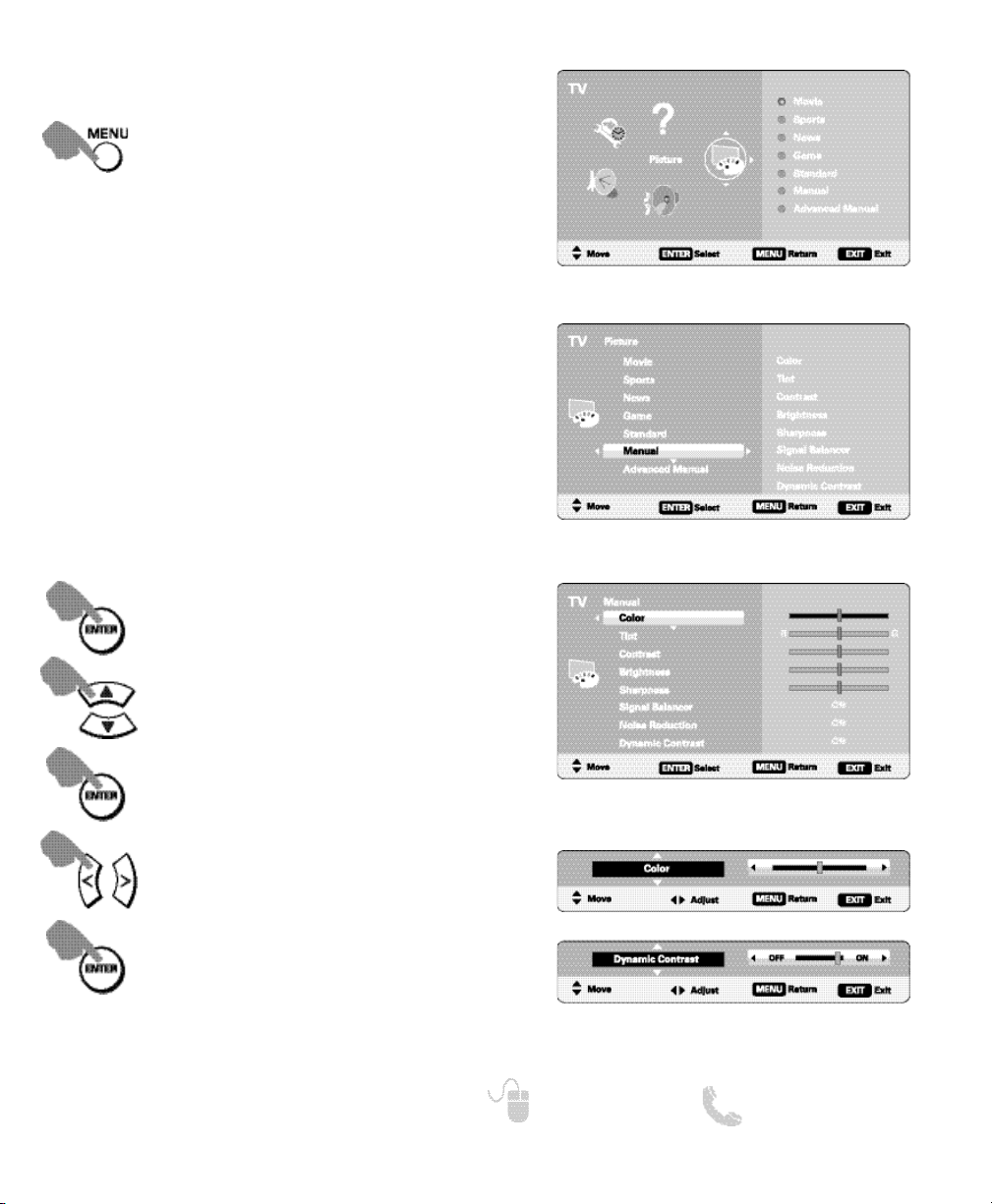
PICTURE
ON-SCREEN MENU OPERATION
Display the On Screen menu and use the
CURSOR keys to select Picture. Press
ENTER.
MAIN MENU SCREEN
You may choose between Movie, Sports, News,
Game, and Standard, which have predetermined fixed
picture parameter values, or one of the two Manual
options for customized personal settings.
NOTE: Each AV input can have its own picture mode (pre-
determined or manual.) Current input’s selected
option is indicated by a blue marker.
Choose Manual to adjust Color, Tint, Contrast,
Brightness, Sharpness, Signal Balancer, Digital Noise
Reduction and Dynamic Contrast values.
Advanced Manual offers a Detailed Setting sub-menu
with the following options: Expanded DNR, White
Balance, Vertical Sharpness, Edge Enhancer, H-Size
and V-Size.
MANUAL PICTURE SETTINGS
Cycle through the different Picture
parameters.
Adjust the value of the selected
parameter.
Enter selected parameter’s adjustment screen.
Set the value of the selected parameter and return to parameter selection screen.
PICTURE SCREEN (MANUAL)
PARAMETER SELECTION SCREEN
Select Manual or Advanced Manual.
VALUE ADJUSTMENT SCREEN EXAMPLES
NOTE:
CURSOR keys select the next/previous
parameter without returning to the previous
menu screen.
16
Need help? www.sanyoctv.com 1-800-877-5032
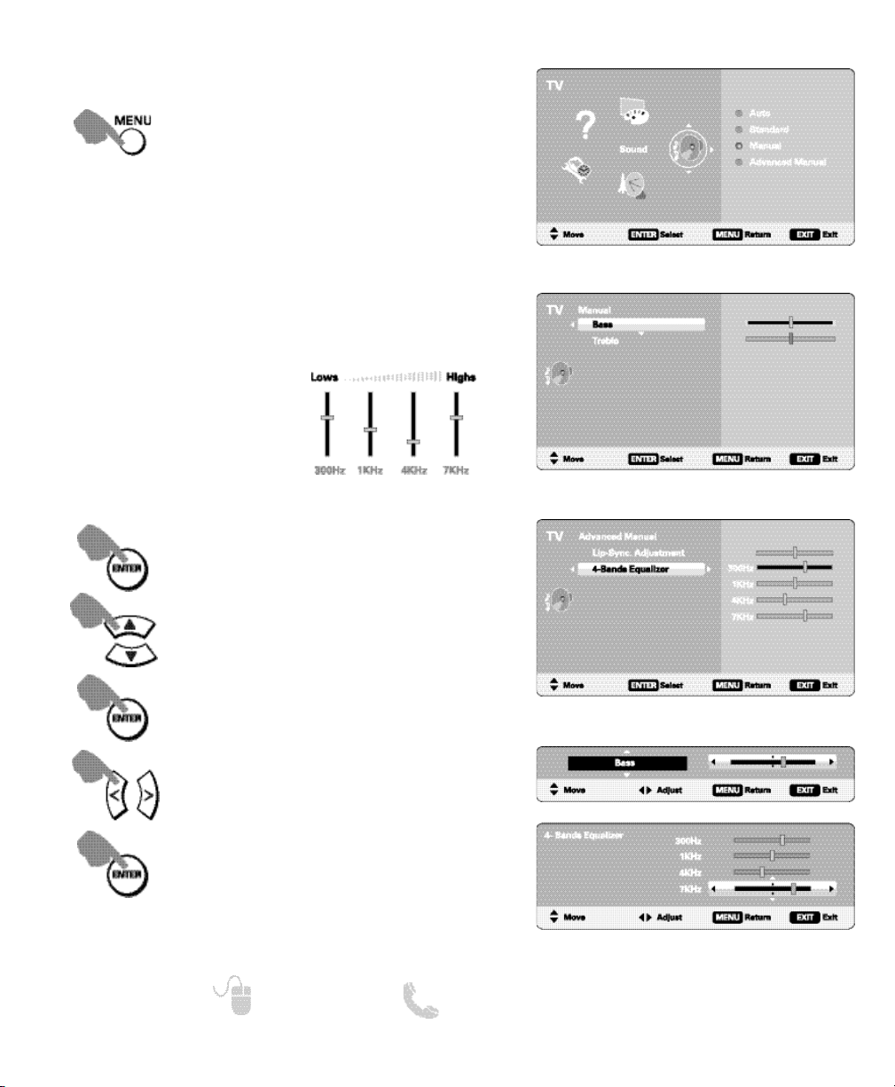
SOUND
Display the On Screen menu and use the
CURSOR keys to select Sound. Press
ENTER.
MAIN MENU SCREEN
MANUAL PARAMETER SCREEN
ADVANCED MANUAL PARAMETER SCREEN
VALUE ADJUSTMENT SCREEN EXAMPLES
Cycle through the different Sound
parameters.
Adjust the value of the selected
parameter.
Enter the selected parameter’s
adjustment screen.
Set the value of the selected parameter and return to parameter selection screen.
Select Manual or Advanced Manual.
ON-SCREEN MENU OPERATION
MANUAL SOUND SETTINGS
Choose one of the four available options for your
sound settings:
Auto – Sound setting levels are adjusted and linked
according to the current Picture option.
Standard – Neutral values for sound parameters.
Manual – Set Bass and Treble levels to your preference.
Advanced Manual – Adjust the audio delay with the
Lyp-Sync Adjustment feature.
Use a 4-Band Equalizer to
personalize sound settings.
17
Need help? www.sanyoctv.com 1-800-877-5032
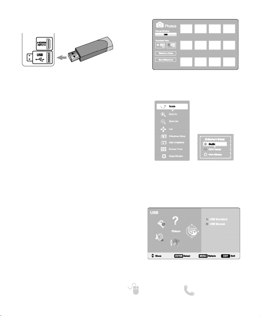
PHOTO VIEWER (USB)
USING THE PHOTO VIEWER
Press ENTER on a thumbnail photo to enable the
Rotate, Full View and Start Slideshow functions.
Once in Full View mode:
Use the CURSOR
< > keys to change picture.
Press ENTER to show the full view options menu.
SLIDE SHOW
In the Slideshow Setup menu you may turn the Shuffle
and Quick Change options ON or OFF.
Press ENTER on Start Slideshow from the Thumbnail
View Screen or from the full view options menu to
start the slideshow from the current picture.
JPEG VIEWER USB MENU
Press MENU when in Full View or Slideshow mode to
display the USB On screen menu.
Picture Setting
– Adjust Color, Tint, Contrast,
Brightness, Sharpness and Dynamic Contrast.
NOTE: Picture Settings are separate configurations from the
settings in TV and AV inputs.
USB MAIN MENU SCREEN
THUMBNAIL VIEW SCREEN
NOTE: A thumbnail hide icon will appear if a pic-
ture cannot be decoded or no thumbnail
data is available.
SLIDE SHOW
SETUP MENU
FULL VIEW
OPTIONS MENU
View pictures on your HDTV with the use of a USB
mass storage device.
HDTV BACK PANEL
NOTE: The HDTV switches to USB Input when a USB device
is detected.
USB DEVICE
 Loading...