


Samsung SH18BW6, SH24BW2, AQV18FA, AQV24FA, AQV18FAN Service Manual
...SPLIT-TYPEAIRCONDITIONER
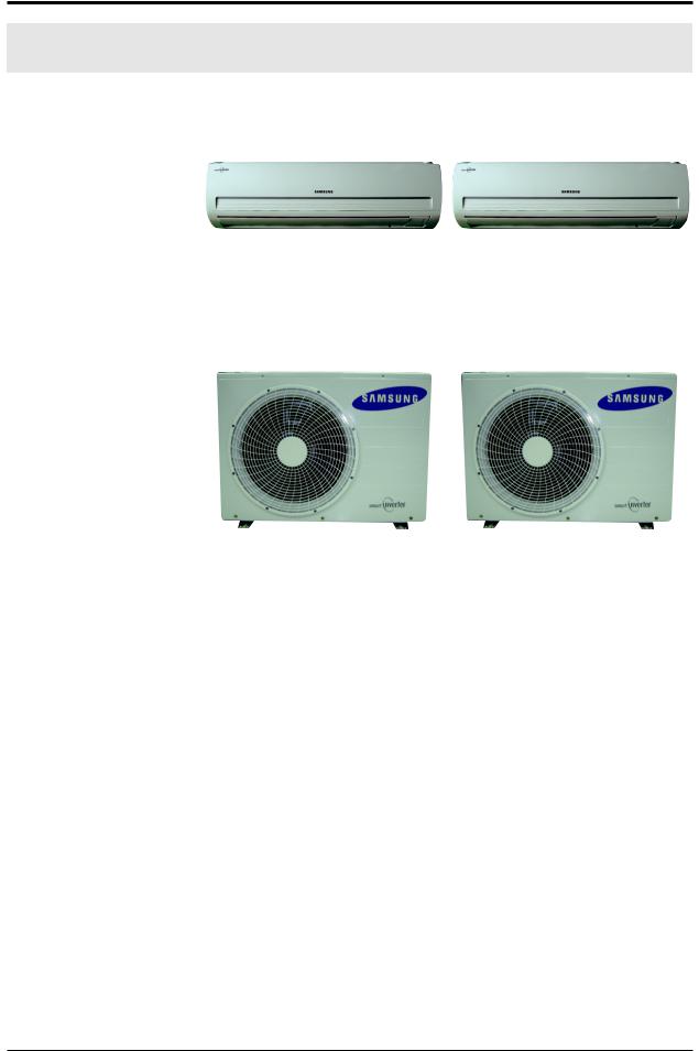
INDOOR UNIT |
OUTDOOR UNIT |
Basic : SH18BW6 |
|
SH24BW2 |
|
Model: AQV18FA |
|
AQV24FA |
|
Model Code : AQV18FAN |
AQV18FAX |
AQV24FAN |
AQV24FAX |
AQV24FANXSA |
AQV24FAXXSA |
AIR CONDITIONER |
THE FEATURE OF PRODUCT |
|
High Energy Efficiency BLDC |
|
Air Conditioner |
|
Simple Flat Grille Design |
|
Good Morning Mode |
|
:GoodMorningModecanhelpyousleepquickly |
AQV18FAN,AQV24FAN,AQV24FANXSA |
andsoundlyandwakeuprefreshed. |
|
Multi Functional Cleaning System |
|
:SilverNanoHealthSystemandDeodorizing/ |
|
CatechinFilterareadopted. |
|
Silence Mode |
|
:Whenyouusethe"SilenceMode",youcan |
|
experienceextremelyquietoperationofyour |
|
airconditioner. |
AQV18FAX,AQV24FAX,AQV24FAXXSA |
|
For more information, Please access to our service web site(http://itself.sec.samsung.co.kr)

Contents
11. Precautions ........................................................................................................................................ |
1-1 |
1-1Installingtheairconditioner .......................................................................................................... |
1-1 |
1-2Powersupplyandcircuitbreaker ................................................................................................. |
1-1 |
1-3Duringoperation .............................................................................................................................. |
1-1 |
1-4Disposingoftheunit ....................................................................................................................... |
1-2 |
1-5Others ................................................................................................................................................. |
1-2 |
12. Product Specifications ............................................................................................................... |
2-1 |
2-1TheFeatureofProduct .................................................................................................................... |
2-1 |
2-2ProductSpecifications ..................................................................................................................... |
2-2 |
2-3TheComparativeSpecificationsofProduct ................................................................................ |
2-3 |
2-4AccessoryandOptionSpecifications ........................................................................................... |
2-5 |
13. Alignment and Adjustments ................................................................................................. |
3-1 |
3-1TestMode ........................................................................................................................................... |
3-1 |
3-2IndoorDisplayErrorandCheckMethod ..................................................................................... |
3-2 |
3-3OutdoorLEDErrorDisplayandCheckMethod .......................................................................... |
3-3 |
3-4SettingOptionSetupMethod ....................................................................................................... |
3-4 |
14. |
Disassembly and Reassembly .............................................................................................. |
4-1 |
|
4-1IndoorUnit ......................................................................................................................................... |
4-2 |
|
4-2OutdoorUnit .................................................................................................................................... |
4-5 |
15. |
Exploded Views and Parts List ............................................................................................. |
5-1 |
|
5-1IndoorUnit ......................................................................................................................................... |
5-1 |
|
5-2OutdoorUnit ..................................................................................................................................... |
5-3 |
|
5-3Ass’yControlIn ................................................................................................................................. |
5-5 |
|
5-4Ass’yControlOut .............................................................................................................................. |
5-7 |
16. |
Electrical Parts List ....................................................................................................................... |
6-1 |
17. |
Wiring Diagram .............................................................................................................................. |
7-1 |
|
7-1IndoorUnit ......................................................................................................................................... |
7-1 |
|
7-2OutdoorUnit .................................................................................................................................... |
7-2 |
18. |
Schematic Diagram ...................................................................................................................... |
8-1 |
|
8-1IndoorUnit ......................................................................................................................................... |
8-1 |
|
8-2OutdoorUnit .................................................................................................................................... |
8-2 |
|
|
|

Contents
19. |
Circuit Descriptions ...................................................................................................................... |
9-1 |
|
9-1PCBCircuitDescriptions .................................................................................................................. |
9-1 |
|
9-2RefrigeratingCycleDiagram .......................................................................................................... |
9-3 |
10. |
PCB Diagram ..................................................................................................................................... |
10-1 |
|
10-1IndoorPCB ....................................................................................................................................... |
10-1 |
|
10-2OutdoorPCB ................................................................................................................................... |
10-2 |
11. |
Operating Instructions .............................................................................................................. |
11-1 |
|
11-1NameofEachPart .......................................................................................................................... |
11-1 |
|
11-2WirelessRemoteControl-ButtonsandDisplay ........................................................................ |
11-3 |
|
11-3MainFunction ................................................................................................................................. |
11-4 |
12. |
Troubleshooting ............................................................................................................................ |
12-1 |
|
12-1Itemstobecheckedfirst .............................................................................................................. |
12-1 |
|
12-2FaultDiagnosisbySymptom ....................................................................................................... |
12-2 |
|
12-3PCBInspectionMethod ................................................................................................................ |
12-20 |
|
12-4MainPartInspectionMethod ...................................................................................................... |
12-22 |
13. |
Block Diagram ................................................................................................................................. |
13-1 |
|
13-1IndoorUnit ...................................................................................................................................... |
13-1 |
|
13-2OutdoorUnit ................................................................................................................................... |
13-3 |
14. |
Reference Sheet .............................................................................................................................. |
14-1 |
|
14-1IndexforModelName .................................................................................................................. |
14-1 |
|
14-2LowRefrigerantPressureDistribution ....................................................................................... |
14-2 |
|
14-3Pressure&Capacitymark ............................................................................................................. |
14-3 |
|
14-4Q&AforNon-trouble ................................................................................................................... |
14-4 |
|
14-5Cleaning/FilterChange ................................................................................................................. |
14-7 |
|
14-6Installation ....................................................................................................................................... |
14-9 |
|
14-7InstallationDiagramofIndoorUnitandOutdoorUnit .......................................................... |
14-10 |

2. Product Specifications
2-1 The Feature of Product
High Energy Efficiency BLDC Air Conditioner
BLDCTechniquearisestheefficiencyofairconditionerandmakesaroomcoolandwarmwithhighenergysaving.
Simple Flat Grille Design
WithaSmartandfashionablestyle,thehighimpressiveinteriordesignallowthisproducttosetplaceinanywhere.
Good Morning Mode
GoodMorningModecanhelpyousleepquicklyandsoundlyandwakeuprefreshed.
Multi functional cleaning system
WithSilverNanoHealthSystemandDeodorizing/CatechinFiltersmakesyourroommorerefreshed.
Silence Mode
Whenyouusethe“SilenceMode”,youcanexperienceextremelyquietoperationofyourairconditioner.
SamsungElectronics |
2-1 |
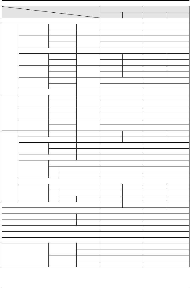
2-2 Product Specifications |
|
|
|
|
|
|||
|
|
|
Model |
AQV18FA |
AQV24FA |
|||
|
|
|
|
|
|
|
||
Item |
|
|
|
IndoorUnit |
OutdoorUnit |
IndoorUnit |
OutdoorUnit |
|
|
|
|
|
|||||
Type |
|
|
|
Wall-mounted |
Wall-mounted |
|||
|
Capacity |
Cooling |
kW |
1.6/5.0/6.0 |
2.2/6.8/8.0 |
|||
|
|
|
|
|
|
|||
|
Heating |
(Low/Std/Max) |
1.5/6.0/7.7 |
1.9/8.0/10.0 |
||||
|
|
|||||||
|
|
|
||||||
|
RunningFrequency |
Cooling |
Hz |
20/67/85 |
15/54/68 |
|||
|
|
|
|
|
|
|||
|
Heating |
(Low/Std/Max) |
20/74/100 |
15/58/85 |
||||
|
|
|||||||
|
|
|
||||||
|
Dehumidifying |
|
ℓ/h |
1.56 |
|
2.81 |
|
|
Performance |
AirVolume |
Cooling |
/min |
11.83/10.90/10.07 |
47 |
13.74/11.97/10.15 |
47 |
|
|
|
|
|
|
||||
Heating |
(H/M/L) |
13.38/12.41/11.47 |
46 |
14.31/12.49/10.55 |
46 |
|||
|
|
|||||||
|
|
|
||||||
|
Noise |
Cooling |
dB |
48/33 |
58 |
48/33 |
60 |
|
|
|
|
|
|
|
|||
|
Heating |
(H/L) |
48/33 |
58 |
48/33 |
60 |
||
|
|
|||||||
|
|
|
||||||
|
EnergyEfficiencyRatio |
Cooling |
W/W |
3.21 |
|
3.01 |
|
|
|
|
|
|
|
|
|||
|
Heating |
(Std) |
3.41 |
|
2.81 |
|
||
|
|
|
|
|||||
|
|
|
|
|
||||
|
Power |
|
ph-V-Hz |
1-220/240-50 |
1-220/240-50 |
|||
|
PowerConsumtion |
Cooling |
W |
500/1560/1950 |
590/2260/2950 |
|||
|
|
|
|
|
|
|||
|
Heating |
(Low/Std/Max) |
450/1760/2600 |
560/2850/4000 |
||||
|
|
|||||||
|
|
|
||||||
Power |
OperatingCurrent |
Cooling |
A |
2.4/7.0/9.0 |
3.0/10.6/13.9 |
|||
|
|
|
|
|
||||
Heating |
(Low/Std/Max) |
2.3/8.0/12.0 |
2.8/13.0/19.0 |
|||||
|
|
|||||||
|
|
|
||||||
|
PowerFactor |
Cooling |
% |
75/90/95 |
75/90/95 |
|||
|
|
|
|
|
|
|||
|
Heating |
(Low/Std/Max) |
75/90/95 |
75/90/95 |
||||
|
|
|||||||
|
|
|
||||||
|
OuterDimension |
WxHxD |
mm |
1065x298x218 |
880x638x310 |
1065x298x218 |
880x638x310 |
|
|
Weight(Net) |
|
kg |
13 |
46 |
13 |
50 |
|
|
RefrigerantPipe |
Liquid |
mmxL(m) |
Φ6.35x5 |
Φ6.35x5 |
|||
|
Gas |
mmxL(m) |
Φ12.7x5 |
Φ15.88x5 |
||||
|
|
|||||||
|
DrainHose |
|
DxL(mm) |
Φ18x550 |
Φ18x550 |
|||
Size |
|
Type |
|
Rotary,G4B135LUAEH |
Rotary,G8T260FUAEW |
|||
Compressor |
Type |
|
Hermetic |
Hermetic |
||||
|
|
|||||||
|
|
Motor |
|
|
|
|
|
|
|
|
RatedOutput |
|
1324W |
2454W |
|||
|
OilType |
|
|
FREOLα68ES-T |
FREOLα68ES-T |
|||
|
|
Type |
|
Cross-flow |
Propeller |
Cross-flow |
Propeller |
|
|
Blower |
Type |
|
Resin/Steel |
Resin/Steel |
Resin/Steel |
Resin/Steel |
|
|
|
Motor |
|
|
|
|
|
|
|
|
RatedOutput |
W |
40 |
90 |
40 |
93 |
|
HeatExchanger |
|
|
2Row16Step |
2Row28Step |
2Row16Step |
2Row28Step |
||
RefrigerantControlUnit |
|
|
EEV |
|
EEV |
|
||
FreezerOilCapacity |
|
cc |
600 |
|
700 |
|
||
RefrigeranttoChange(R410A) |
|
g |
1,450 |
1,450 |
|
|||
ProtectionDevice(OLP) |
|
|
None |
None |
|
|||
CoolingTestCondition |
|
|
IndoorUnit:DB27°CWB19°C |
OutdoorUnit:DB35°CWB24°C |
||||
HeatingTestCondition |
|
|
IndoorUnit:DB20°CWB15°C |
OutdoorUnit:DB7°CWB6°C |
||||
|
|
cooling |
indoor |
16°C~32°C |
16°C~32°C |
|||
|
|
Outdoor |
-10°C~43°C |
-10°C~43°C |
||||
Operationconditonrange |
|
|||||||
|
indoor |
27°Corless |
27°Corless |
|||||
|
|
heating |
||||||
|
|
Outdoor |
-15°C~24°C |
-15°C~24°C |
||||
|
|
|
||||||
2-2 |
|
|
|
|
|
SamsungElectronics |
||
2-3 The Comparative Specifications of Product
Item |
|
Development Model |
Comparative Model |
|
|
|
|
||
|
AQV18FA |
AQV24FA |
||
|
|
|||
|
|
|
|
|
|
IndoorUnit |
|
|
|
Design |
|
|
|
|
OutdoorUnit |
|
|
||
|
|
|
||
|
|
|
|
|
NetWeight |
IndoorUnit |
13kg |
13kg |
|
|
|
|
||
OutdoorUnit |
46kg |
50kg |
||
|
||||
|
|
|
|
|
OuterDimension |
IndoorUnit |
1065x298x218(mm³) |
1065x298x218(mm³) |
|
|
|
|
||
(WidthxHeightxDepth) |
OutdoorUnit |
880x638x310(mm³) |
880x638x310(mm³) |
|
|
|
|
|
|
Noise |
IndoorUnit |
48dB↓ |
48dB↓ |
|
|
|
|
||
OutdoorUnit |
58dB↓ |
60dB↓ |
||
|
||||
|
|
|
|
|
|
|
SilverNanoEvaporator |
SilverNanoEvaporator |
|
AirPurifyingSystem |
Filter |
CatechinFilter |
CatechinFilter |
|
|
|
DeodorizingFiter |
DeodorizingFiter |
|
|
|
|
|
|
IndoorDisplay |
ThreeColorLEDDisplay |
ThreeColorLEDDisplay |
||
|
|
|
|
|
SamsungElectronics |
2-3 |
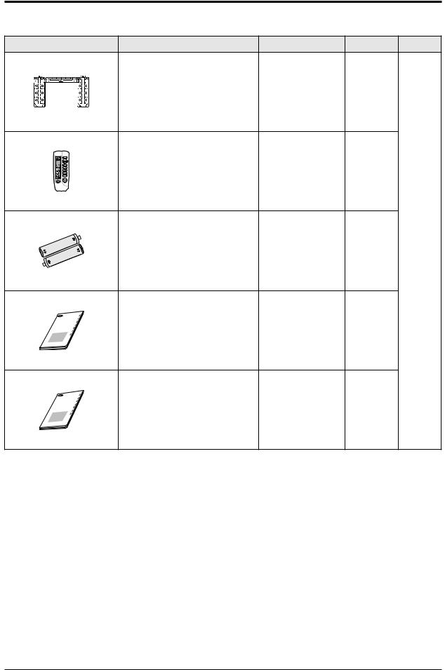
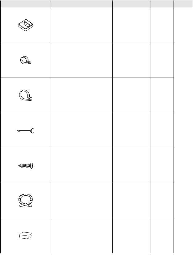
2-4 Accessory and Option Specifications
2-4-1 Accessories
Item |
Descriptions |
Code-No. |
Q'TY |
Remark |
Ass'yPlateHanger |
DB90-02738A |
1 |
RemoteControl |
DB93-03170S |
1 |
BatteriesforRemoteControl |
DB47-90024A |
2 |
Indoor |
|
Unit |
||||
|
|
|
|
TIONS |
OWNER'SINSTRUC |
|
ISMTRAUNZIUAOLNIDPEEINSRL'TRUSUOCCIONES |
|
MANANUUEALLDD'UTEIILNSISTRATUIO‚ÍNES |
|
GEBRAUM |
CHSANWEISUNG |
User’sManual |
DB98-26678A |
1 |
|
|
NS |
OWNER'SINSTRUCTIO |
||
MANZUIALONIDPEEINRSLT'URSUOCCIONES |
||
ISTRU |
INSTRU‚ÍES |
|
MANUALD'UTILISDE |
ATION |
|
GEBRAUMANUECHSANL |
WEISUNG |
|
InstallationManual |
DB98-26680A |
1 |
2-4 |
SamsungElectronics |
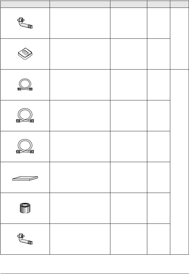
Item |
AssemblyPipe,ø6.35mm |
DB96-06553A |
1 |
Remark |
|
AssemblyPipe,ø12.70mm |
DB96-06553E |
1 |
|||
**18** |
|||||
|
|
||||
AssemblyPipe,ø15.88mm |
DB96-06553G |
1 |
|||
**24** |
|||||
|
|
||||
PET3FoamTubeInsulation |
DB72-50165A |
1 |
|||
VinylTape,Width50mm |
DB72-00459A |
1 |
|||
DrainPlug |
DB67-20011A |
1 |
|||
Descriptions |
Code-No. |
Q'TY |
|||
|
DrainPlug |
DB67-20011A |
1 |
|
|
|
|
|
|
Outdoor |
|
|
|
|
|
Unit |
|
|
RubberLeg |
DB73-20134A |
4 |
|
|
|
|
|
|
Accessory |
|
|
|
|
|
Box |
SamsungElectronics |
2-5 |
Product Specifications
Accessories(cont.)
Item |
Descriptions |
Code-No. |
Q'TY |
Remark |
RubberLeg |
DB73-20134A |
4 |
PipeClampsA |
DB39-20224A |
3 |
PipeClampsB |
DB39-20224B |
3 |
CementNail |
- |
6 |
Accessory |
|
Box |
||||
|
|
|
M4x16TappingScrews |
6002-000215 |
10 |
DrainHose,length2m |
DB62-00487A |
1 |
Putty100g |
DB98-10568A |
1 |
2-6 |
SamsungElectronics |
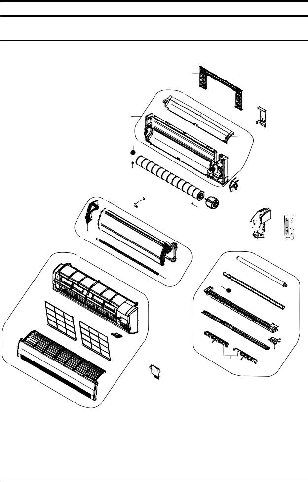
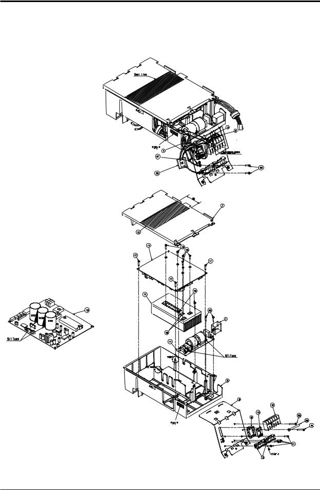
5. Exploded Views and Parts List
5-1 Indoor Unit
6
1
14
15
12
2
 16
16
2-1
2-3
2-2 2-4
2-5
55-1
5-5
3
5-2


5-4
8
7
1-2
1-1

 10
10
11
13
4

 9
9


3-6 3-8
3-4
3-1

 3-7
3-7
3-2
 3-5 3-3
5-3
5-1 |
SamsungElectronics |
Exploded Views and Parts List
Parts List
No. |
Code No. |
Description |
Specification |
Q’TY |
SA/SNA |
||
|
|
||||||
AQV18FAN |
AQV24FAN |
||||||
|
|
|
|
|
|||
|
|
|
|
|
|
|
|
1 |
DB94-00615B |
ASS’YBACKBODY |
ASS’Y |
1 |
1 |
SA |
|
1-1 |
DB61-01974B |
BACKBODY |
HIPS |
1 |
1 |
SNA |
|
1-2 |
DB69-01039A |
CUSHIONBACKBODY |
EPS |
1 |
1 |
SNA |
|
2 |
DB96-06587B |
ASS’YEVAPTOTAL |
ASS’Y |
1 |
- |
SA |
|
DB96-06587C |
ASS’YEVAPTOTAL |
ASS’Y |
- |
1 |
SA |
||
|
|||||||
2-1 |
DB63-01065A |
COVERBEARING |
ABS |
1 |
1 |
SNA |
|
2-2 |
DB96-06587B |
ASS’YEVAPMAIN |
ASS’Y |
1 |
1 |
SNA |
|
DB96-06525B |
ASS’YEVAPSUB |
ASS’Y |
1 |
1 |
SNA |
||
|
|||||||
2-3 |
DB96-03756B |
ASS’YTUBEEVAPOUT |
ASS’Y |
1 |
- |
SA |
|
DB96-03756A |
ASS’Y |
- |
1 |
SA |
|||
|
|
||||||
2-4 |
DB96-06500B |
ASS’YTUBEEVAPIN |
|
1 |
1 |
SA |
|
2-5 |
DB60-00192A |
SPACEREVAPLOW |
|
1 |
1 |
SNA |
|
3 |
DB94-00616E |
ASS’YTRAYDRAIN |
ASS’Y |
1 |
1 |
SA |
|
3-1 |
DB63-01071A |
TRAYDRAIN |
ABS |
1 |
1 |
SNA |
|
3-2 |
DB61-01975C |
BLADE-H |
HIPS |
1 |
1 |
SA |
|
3-3 |
DB61-01976A |
BLADE-V |
PP |
2 |
2 |
SA |
|
3-4 |
DB63-01066A |
TRAYSTABILIZER |
ABS |
1 |
1 |
SNA |
|
3-5 |
DB69-01024A |
CUSHIONEPSTRAYRH |
EPS |
1 |
1 |
SA |
|
3-6 |
DB73-00180A |
RUBBERCAPDRAIN |
GUM-EPM |
1 |
1 |
SNA |
|
3-7 |
DB31-00285A |
ASS’YMOTORSTEPPING |
220-240V~,50/60Hz, |
1 |
1 |
SA |
|
ClassE |
|||||||
|
|
|
|
|
|
||
3-8 |
DB94-00458B |
ASS’YDRAINHOSE |
ASS’Y |
1 |
1 |
SA |
|
4 |
DB93-04261A |
ASS’YCONTROLIN |
ASS’Y |
1 |
1 |
SA |
|
5 |
DB92-00850H |
ASS’YPANELFRONT |
ASS’Y |
1 |
1 |
SA |
|
5-1 |
DB64-01184C |
PANELFRONT |
HIPS |
1 |
1 |
SA |
|
5-2 |
DB64-01630D |
GRILLEAIRINLET |
HIPS |
1 |
1 |
SA |
|
5-3 |
DB64-01654B |
DECORATIONGRILLE |
PC(GRAY) |
1 |
1 |
SA |
|
5-4 |
DB93-02867C |
ASS’YCOVERDISPLAY |
ASS’Y |
1 |
1 |
SA |
|
5-5 |
DB63-01592A |
GUARDAIRFILTER |
PP |
2 |
2 |
SNA |
|
6 |
DB90-02738A |
ASS’YPLATEHANGER |
ASS’Y |
1 |
1 |
SNA |
|
7 |
DB61-01981B |
HOLDERPIPE |
PS |
1 |
1 |
SNA |
|
8 |
DB63-01063C |
COVERTERMINAL |
ABS |
1 |
1 |
SA |
|
9 |
DB93-03170S |
ASS’YREMOCON |
ARH-463 |
1 |
1 |
SA |
|
10 |
DB96-03817A |
ASS’YSUPPORTEVAPRH |
HIPS |
1 |
1 |
SA |
|
11 |
DB31-00267A |
MOTORIN |
220-240V~,50/60Hz, |
1 |
1 |
SA |
|
ClassE |
|||||||
|
|
|
|
|
|
||
12 |
DB94-00456B |
ASS’YCROSSFAN |
OD92 |
1 |
1 |
SA |
|
13 |
DB97-02075A |
ASS’YBOLTSPECIAL |
ASS’Y |
1 |
1 |
SNA |
|
14 |
DB94-00455A |
ASS’YRUBBERBEARING |
ASS’Y |
1 |
1 |
SNA |
|
15 |
DB94-40007A |
ASS’YBEARINGMOTOR |
BEARING |
1 |
1 |
SA |
|
16 |
DB61-01977A |
BRACKETEVAP |
SGCC-M |
1 |
1 |
SA |
|
|
|
|
|
|
|
|
|
SamsungElectronics |
5-2 |
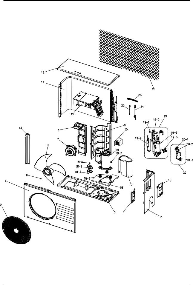
5-2 Outdoor Unit
5-3 |
SamsungElectronics |

Exploded Views and Parts List
Parts List
No. |
Code No. |
Description |
Specification |
Q’TY |
SA/SNA |
||
|
|
||||||
AQV18FAX |
AQV24FAX |
||||||
|
|
|
|
|
|||
|
|
|
|
|
|
|
|
1 |
DB90-01146D |
ASS’YCABIFRONT |
ASS’Y,SC-94445T |
1 |
1 |
SA |
|
2 |
DB63-00838A |
GUARDFAN |
HIPS,SC-90073R |
1 |
1 |
SA |
|
3 |
DB90-00970T |
ASS’YBASEOUT |
ASS’Y,SC-94445T |
1 |
- |
SA |
|
DB90-00970K |
- |
1 |
|||||
|
|
|
|
||||
4 |
DB61-01593A |
BRACKETVALVE |
SECC-P,SC-94445T |
1 |
1 |
SA |
|
5 |
DB67-00142A |
FAN-PROPELLER |
AS+G/F20%,Φ420 |
1 |
1 |
SA |
|
6 |
DB60-30020A |
NUT-HEXAGON |
M6 |
1 |
1 |
SA |
|
7 |
DB31-00264D |
MOTORFANOUT |
ACMotor |
1 |
1 |
SA |
|
8 |
DB61-00686A |
BRACKETMOTOR |
SGCC-M |
1 |
1 |
SA |
|
9 |
DB94-01210A |
ASS’YPARTITION |
ASS’Y,SGCC-M |
1 |
1 |
SA |
|
10 |
DB27-00043A |
REACTOR |
PPS,20A |
1 |
1 |
SA |
|
11 |
DB96-04087B |
ASS’YCONDUNIT |
ASS’Y |
1 |
1 |
SA |
|
12 |
DB90-10616G |
ASS’YCABIUP |
ASS’Y,SC-94445T |
1 |
1 |
SA |
|
13 |
DB63-00692A |
GUARDCOND |
SECC-P,SC-94445T |
1 |
1 |
SA |
|
14 |
DB90-01651B |
ASS’YCABINETSIDERH |
ASS’Y,SC-94445T |
1 |
1 |
SA |
|
15 |
DB90-40176B |
COVERCONTROL |
ABS,SC-90073R |
1 |
1 |
SA |
|
16 |
DB63-01718A |
FELTCOMPBASE |
FELT+PVCSheet |
1 |
- |
SA |
|
DB63-01719A |
- |
1 |
|||||
|
|
|
|
||||
17 |
DB63-01669A |
FELTCOMPSIDE |
FELT+PVCSheet |
1 |
- |
SA |
|
DB63-01668A |
- |
1 |
|||||
|
|
|
|
||||
18 |
G4B135LUAEH |
COMPRESSOR |
ROTARY,BLDC |
1 |
- |
SNA |
|
G8T260FUAEW |
- |
1 |
|||||
|
|
|
|
||||
18-1 |
DB63-00763A |
GROMMETISOLATOR |
NR |
3 |
- |
SNA |
|
DB63-00815A |
- |
3 |
|||||
|
|
|
|
||||
18-2 |
DB60-30028A |
SCREWHEX |
M8 |
3 |
3 |
SNA |
|
18-3 |
DB63-00817A |
GASKET |
EPDM |
1 |
1 |
SNA |
|
18-4 |
DB63-00816A |
COVERTERMINAL |
PBT(G/F15%) |
1 |
1 |
SNA |
|
18-5 |
6021-001142 |
SCREWMACHINE |
M5 |
1 |
1 |
SNA |
|
19 |
DB99-00851A |
ASS’YVALVE4WAY |
ASS’Y |
1 |
1 |
SA |
|
DB99-00852A |
|
|
|||||
|
|
|
|
|
|
||
19-1 |
DB62-02338A |
4WAYVALVE |
R410A,SANHUA |
1 |
1 |
SNA |
|
19-2 |
DB33-00002C |
SOLENOIDCOIL |
ASS’Y |
1 |
1 |
SNA |
|
19-3 |
DB67-00765A |
ACCUMULATOR |
STEELACCUM. |
1 |
1 |
SNA |
|
19-4 |
DB97-02054A |
TUBEMUFFLER |
C1220T-0 |
1 |
- |
SNA |
|
19-5 |
DB62-02285A |
VALVESERVICE |
R410A,SANHUA,1/2” |
1 |
- |
SNA |
|
DB62-02342A |
R410A,SANHUA,5/8” |
- |
1 |
||||
|
|
|
|||||
20 |
DB96-06744A |
ASS’YVALVEEEV |
|
1 |
1 |
SA |
|
20-1 |
DB62-03964A |
VALVEEXPANSIONCOIL |
FUJIKOKI |
1 |
1 |
SNA |
|
20-2 |
DB62-02863A |
VALVEEXPANSIONBODY |
FUJIKOKI |
1 |
1 |
SNA |
|
20-3 |
DB62-02283A |
VALVESERVICE |
R410A,SANHUA,1/4” |
1 |
1 |
SNA |
|
21 |
DB61-00821B |
GUIDESCREEN |
P.E.H100% |
1 |
1 |
SA |
|
22 |
DB93-04268B |
ASS’YCONTROLOUT |
ASS’Y |
1 |
- |
SA |
|
DB93-04268A |
ASS’YCONTROLOUT |
ASS’Y |
- |
1 |
SA |
||
|
|||||||
23 |
DB32-00176A |
THERMISTOROUT/DIS |
ASS’Y |
1 |
1 |
SA |
|
24 |
DB32-00175A |
THERMISTORCOND |
ASS’Y |
1 |
1 |
SA |
|
25 |
DB39-01301B |
CONNECTWIRECOMP |
ASS’Y |
1 |
1 |
SA |
|
|
|
|
|
|
|
|
|
SamsungElectronics |
5-4 |
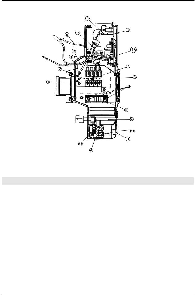
5-3 Ass'y Control In : DB93-04261A
Parts List
No. |
Code No. |
Description |
Specification |
Q’ty |
SN/SNA |
|
|
|
|
|
|
1 |
DB61-01979A |
CASE-CONTROLIN |
ABS |
1 |
SA |
2 |
DB65-00004U |
TERMINALBLOCK |
DAF-4P |
1 |
SNA |
3 |
DB93-04255A |
ASSY-PCBINMAIN |
FORTE,18K/24K |
1 |
SA |
4 |
DB93-03117A |
ASSY-PCBDISPLAY |
WW1Dynamic |
1 |
SNA |
5 |
DB70-00507A |
PLATECONTROLIN |
SGCC-M,T1.2 |
1 |
SNA |
6 |
DB61-01097A |
HOLDERWIRECLAMP |
ABS,BLK |
1 |
SA |
7 |
6001-000929 |
SCREW |
PH+,M3,L23 |
1 |
SNA |
8 |
6001-001054 |
SCREW |
TH+,M4.L16 |
3 |
SNA |
9 |
DB93-04832A |
CONNECTWIRE |
STEPMOTOR |
1 |
SNA |
10 |
DB32-00020H |
SENSOR |
4P(103AT) |
1 |
SA |
11 |
DB63-00851A |
COVERDRAIN |
ABS |
1 |
SNA |
12 |
DB73-00242B |
RUBBERBAND |
RUBBER |
1 |
SNA |
13 |
DB39-00765T |
CONNECTWIRE |
BRN |
1 |
SNA |
14 |
DB39-01193A |
CONNECTWIRE |
SKYBLU,3P |
1 |
SNA |
15 |
DB39-01210B |
CONNECTWIRE |
RED/BLU |
1 |
SNA |
16 |
DB93-04685A |
CONNECTWIRE |
DISPLAY |
1 |
SNA |
17 |
DB39-00148A |
CONNECTWIRE |
EARTH |
1 |
SNA |
18 |
6009-001001 |
SCREW |
TH+,M4,L8 |
1 |
SNA |
19 |
DB93-04257A |
ASSYPCB-INDOOR485 |
24K/18K(INDOOR) |
1 |
SNA |
5-5 |
SamsungElectronics |

MEMO
SamsungElectronics |
5-6 |
5-4 Ass'y Control Out
AQV18FAX : DB93-04268B
AQV24FAX : DB93-04268A
5-7 |
SamsungElectronics |

Exploded Views and Parts List
Parts List
No. |
Code No. |
Description |
Specification |
|
Q’ty |
SA/SNA |
|
|
|
|
|||||
AQV18FAX |
|
AQV24FAX |
|||||
|
|
|
|
|
|
||
|
|
|
|
|
|
|
|
1 |
2301-001378 |
C-FILM,LEAD-OTHER |
3.5uF,450V |
1 |
|
- |
SA |
2301-001379 |
C-FILM,LEAD-OTHER |
4.0uF,450V |
- |
|
1 |
SA |
|
|
|
||||||
2 |
DB93-04339A |
ASSYLEADWIRE |
SKYBLU |
1 |
|
1 |
SNA |
3 |
DB93-04339B |
ASSYLEADWIRE-POWERL |
BRN |
1 |
|
1 |
SNA |
4 |
DB93-04337A |
ASSYCONNECTORWIRE |
5P,MAINTODISPLAY |
1 |
|
1 |
SNA |
5 |
DB61-01097A |
HOLDER-WIRECLAMP |
ABS,BLK |
2 |
|
2 |
SA |
6 |
DB61-02973A |
CASE-CONTROLBASE |
ABSV0,T2.0 |
1 |
|
1 |
SNA |
7 |
DB61-02974A |
CASE-CONTROLCOVER |
ABSV0,T2.0 |
1 |
|
1 |
SNA |
8 |
DB61-02977A |
PLATE-CONTROLOUT |
SGCC_M,T0.6 |
1 |
|
1 |
SNA |
9 |
DB61-02975A |
CASE-DISPLAYPCB |
ABSV0,T2.0 |
1 |
|
1 |
SNA |
10 |
DB62-04566B |
SEAL-COVERCONTROL |
FOAM-LEX,T2,WHT |
1 |
|
1 |
SNA |
11 |
DB62-04626A |
HEATSINK |
100mm,185mm,50mmm,AL |
1 |
|
1 |
SNA |
12 |
DB65-00181C |
TERMINALBLOCK |
DAF-6P |
1 |
|
1 |
SNA |
13 |
DB93-04266B |
ASSYPCBMAIN-OUT |
PCB-2L |
1 |
|
- |
SA |
DB93-04266A |
ASSYPCBMAIN-OUT |
PCB-2L |
- |
|
1 |
SA |
|
|
|
||||||
14 |
DB93-04267B |
ASSYPCBSUB-EMI |
PCB-2L |
1 |
|
- |
SA |
DB93-04267A |
ASSYPCBSUB-EMI |
PCB-2L |
- |
|
1 |
SA |
|
|
|
||||||
15 |
DB93-04329A |
ASSYPCBDISPLAY |
PCB-1L |
1 |
|
1 |
SA |
16 |
DB98-17991A |
ASSY-INSULATORMICA |
MICA |
2 |
|
2 |
SNA |
17 |
6002-000630 |
SCREW-TAPPING |
PH+,M2,L8 |
3 |
|
3 |
SNA |
18 |
DB91-00306A |
ASSY-SCREWMACHINE |
PH+,M3,L16 |
3 |
|
3 |
SNA |
19 |
DB91-00307A |
ASSY-SCREWMACHINE |
PH+,M4,L16 |
4 |
|
4 |
SNA |
20 |
6002-000555 |
SCREW-TAPPING |
PH+,M4,L25 |
1 |
|
1 |
SNA |
21 |
6001-001054 |
SCREW-MACHINE |
TH+,M4,L10 |
4 |
|
4 |
SNA |
22 |
6009-001001 |
SCREW-SPECIAL |
TH+,M4,L8 |
1 |
|
1 |
SNA |
23 |
6002-000536 |
SCREW-TAPPING |
PH+,M4,L10 |
2 |
|
2 |
SNA |
25 |
DB61-00206B |
HOLDER-WIRE |
SGCC_M,T0.5 |
1 |
|
1 |
SNA |
26 |
6002-000231 |
SCREW-TAPPING |
PH+,M4,L10 |
1 |
|
1 |
SNA |
27 |
DB65-10088D |
CABLE-TIE |
NYLON66 |
1 |
|
1 |
SNA |
28 |
DB95-01040C |
ASSYNOISEABSORBER |
ASSY |
1 |
|
1 |
SNA |
|
|
|
|
|
|
|
|
SamsungElectronics |
5-8 |

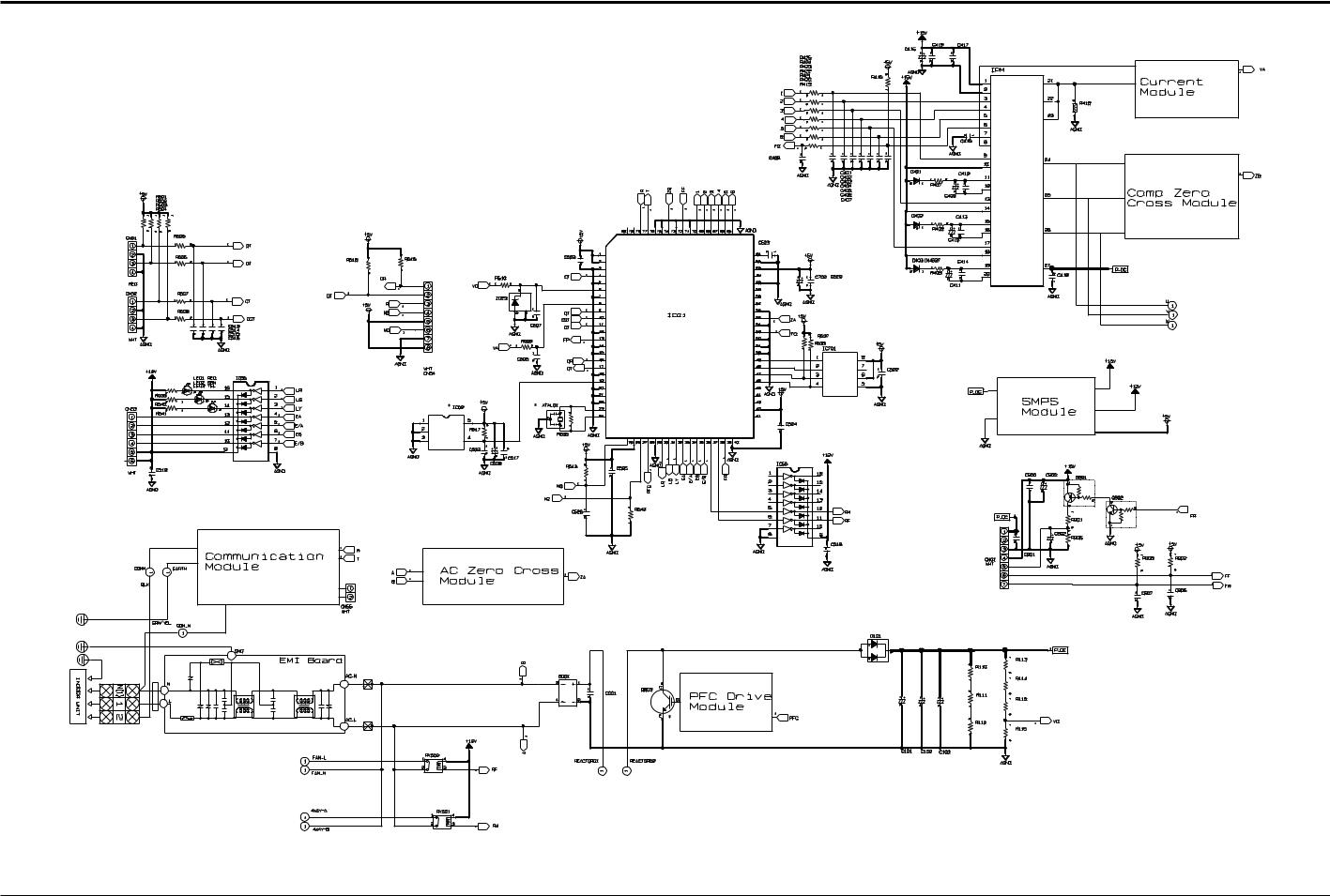
8. Schematic Diagram
8-1 Indoor Unit
ThisDocumentcannotbeusedwithoutSamsung’sauthorization.
SamsungElectronics |
8-1 |
8-2 Outdoor Unit
ThisDocumentcannotbeusedwithoutSamsung’sauthorization.
SamsungElectronics |
8-2 |
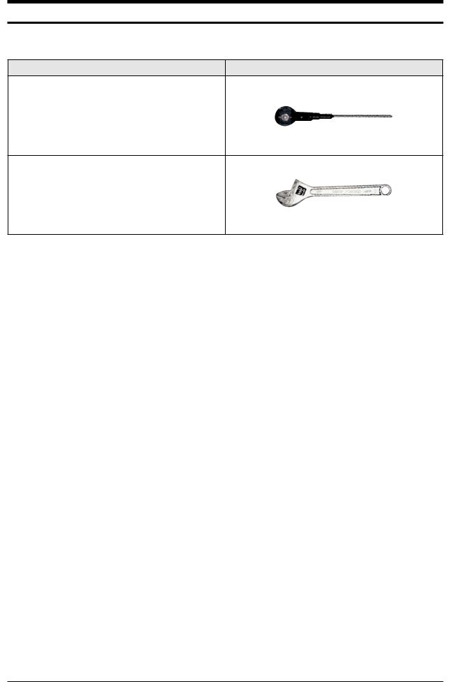
4. Disassembly and Reassembly
Necessary Tools
Item |
Remark |
+SCREWDRIVER
MONKEYSPANNER
SamsungElectronics |
4-1 |
4-1 Indoor Unit
No |
Parts |
Procedure |
Remark |
|
|
|
|
|
|
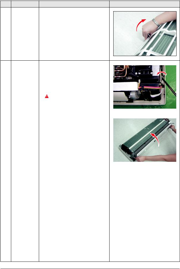
1 |
FrontGrille |
1) Stoptheairconditioneroperationand |
|
|
|
|
|||
|
|
shutoffthemainpower. |
|
|
|
|
|
|
|
2)OpentheFrontGrillebypullingrightand leftsidesofthehook.
3)Loosen1oftherightscrew(CCW)anddetach theTerminalCover.(Use+ScrewDriver.)
4)DetachthethermistorfromtheFrontGrille.
5) Loosen2fixingscrews(CCW)ofFrontGrille.
6)Unlock3hookstofixPanelFrontandTray Drain.(Use+ScrewDriver.)
4-2 |
SamsungElectronics |
Disassembly and Reassembly
No |
Parts |
Procedure |
Remark |
7)Unlock3hookstofixPanelFrontand Back-Body.
2 |
Control-In |
1) |
TakealltheconnectorofPCBuppersideout. |
|
|
|
|
||||
|
(Main PCB) |
|
(InclusionPowerCord) |
|
|
|
|
2) |
Detachtheoutdoorunitconnectionwirefrom |
|
|
|
|
|
theTerminalBlock. |
|
|
|
|
3) |
Loosen4fixingscrews(CCW)ofAss'y |
|
|
|
|
|
Control-In.(Use+ScrewDriver.) |
|
|
|
|
|
YoucandisassemblyAss'yControlIn |
|
|
|
|
|
withoutevaporatordisassembled. |
|
|
|
|
|
|
|
|
|
|
|
|
|
|
3 |
Tray Drain |
1) |
PullTrayDrainoutfromtheBackBody. |
|
|
|
|
||||
|
|
|
|
|
|
SamsungElectronics |
4-3 |

Disassembly and Reassembly
No |
Parts |
|
Procedure |
Remark |
|
|
|
|
|
|
|
4 |
Heat Exchanger |
1) |
Loosen2fixingearthscrews(CCW)ofright |
|
|
|
|
||||
|
|
|
side.(Use+ScrewDriver.) |
|
|
|
|
2) |
DetachtheConnectionPipe. |
|
|
|
|
3) |
DetachtheHolderPipeattherearside. |
|
|
|
|
|
|
|
|
4)Loosenthe4fixingscrews(CCW)ofrightand leftside.(Use+ScrewDriver.)
5)LiftingtheHeatExchangerupalittletopush theupsideforseparationfromtheindoor unit.
 First,checkComp.Downandthendisconnect theconnectionpipesbeforeyoudisassemble theEvaporatorfromindoorunit.
5 |
Fan Motor |
1) |
Loosenthefixingscrew(CCW). |
|
& |
|
(Use+ScrewDriver.) |
|
Cross Fan |
2) |
DetachtheFanMotorfromtheFan. |
|
|
3) |
DetachtheFanFromtheleftHolderBearing. |
4-4 |
SamsungElectronics |
4-2 Outdoor Unit
No |
Parts |
Procedure |
Remark |
|
|
|
|
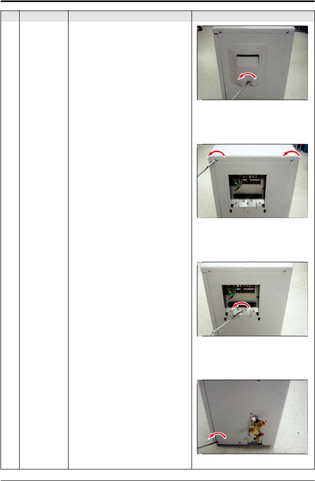
1 |
Common Work |
1)Loosen1fixingscrew(CCW)oftheCover- |
|
|
|
ControlanddetachtheCoverControl. |
|
2)Loosenfixingscrews(CCW)anddetachthe Cabinet-Upper.
3)Loosen1screw(CCW)fixedtoassembleControl BoxwithCabinet-SideRH.
4)Loosen6fixingscrews(CCW)anddetachthe Cabinet-SideRH.
SamsungElectronics |
4-5 |
Disassembly and Reassembly
No |
Parts |
Procedure |
Remark |
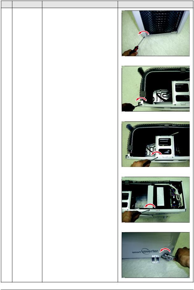
5)Loosen2screws(CCW)fixedontheGuide Condenser.
6)Loosenfixingscrews(CCW)oftheCabinet Front.
4-6 |
SamsungElectronics |
Disassembly and Reassembly
No |
Parts |
Procedure |
Remark |
|
|
|
|
2 |
Fan |
1)DetachtheNutFlangelikethepictureon |
|
&therightside.(Turnclockwisebecausethe
Motor |
screwisleft-handed.) |
|
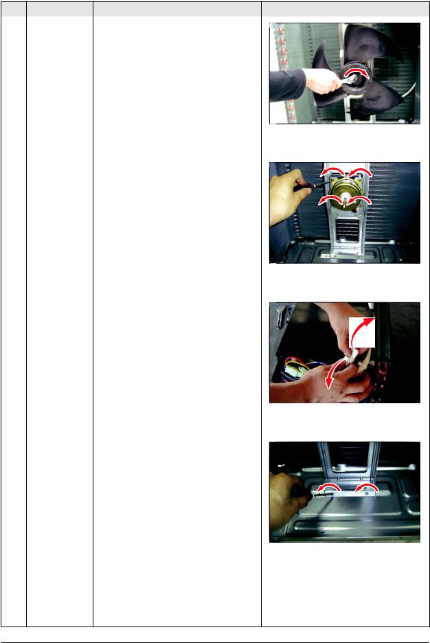
2)DetachtheFanPropeller.
3)Loosen4fixingscrews(CCW)todetach theMotor.
4)DisconnectthewirebetweenAss’yControl OutandMotor.
5)Loosen2fixingscrews(CCW)anddetachthe BracketMotor.
SamsungElectronics |
4-7 |
Disassembly and Reassembly
No |
Parts |
Procedure |
Remark |
|
|
|
|
3 |
Ass’yControlOut |
1)Detachseveralconnectorsfromthe |
|
|
|
Ass’yControlOut. |
|
|
|
2)DetachseveralconnectorsfromthePCBof |
|
|
|
Ass’yControlOut. |
|
|
|
3)PulluptheAss’yControlOut. |
|
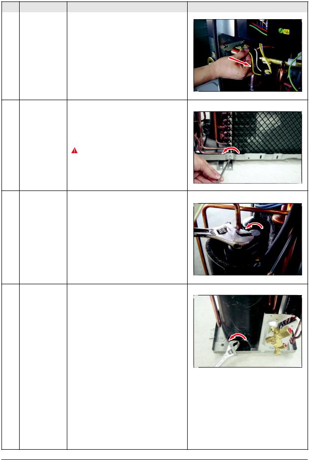
4 |
HeatExchanger |
1)Releasetherefrigerantatfirst. |
|
|
2)Loosenfixingscrew(CCW). |
|
|
3)Disassemblethepipesinbothinletandoutlet |
|
|
withweldingtorch. |
|
|
4)DetachtheHeatExchanger. |
|
|
Beforeyoudisassemblethepipesand |
|
|
Condenser,besurethatthereshouldbe |
|
|
norefrigerantremainedintheunit. |
5 |
Compressor |
1)Loosenthefixingnut(CCW)anddetachthe |
|
|
CompressorLeadWire. |
2)DisassembletheFeltCompSound.
3)Loosenthe3bolts(CCW)atthebottomof Compressorlikethepictureontherightside.
4-8 |
SamsungElectronics |

MEMO
SamsungElectronics |
4-9 |
12. Troubleshooting
12-1 Items to be checked first
1.Theinputvoltageshouldberatingvoltage±10%range.
Theairconditionermaynotoperateproperlyifthevoltageisoutofthisrange.
2.Isthelinkcablelinkingtheindoorunitandtheoutdoorunitlinkedproperly? Theindoorunitandtheoutdoorunitshallbelinkedby5cables.
Checktheterminalsiftheindoorunitandoutdoorunitareproperlylinkedbythesamenumberofcables. Otherwisetheairconditionermaynotoperateproperly.
3.Whenaproblemoccursduetothecontentsillustratedinthetablebelowitisasymptomnotrelatedtothemalfunctionofthe airconditioner.
No |
Operation of air conditioner |
Explanation |
|
|
|
1 |
The OPERATION indicationLED(BLUE)blinkswhenapower |
Itindicatespowerison.TheLEDstopsblinkingiftheoperation |
|
plugoftheindoorunitispluggedinforthefirsttime. |
ON/OFFbuttonontheremotecontrolunitispushed. |
|
|
|
2 |
InaCOOLoperationmode,thecompressordoesnot |
Inhappensafteradelayof3minuteswhenthecompressoris |
|
operateataroomtemperaturehigherthanthesetting |
reoperated.Thesamephenomenonoccurswhenapowerison. |
|
temperaturethattheINDOORFANshouldoperate. |
Asaphenomenonthatthecompressorisreoperatedaftera |
|
[In case of heat pump model] |
delayof3minutes,theindoorfanisadjustedautomaticallywith |
|
InaHEAToperationmode,thecompressordoesnot |
referencetoatemperatureoftheairblew. |
|
operateataroomtemperaturelowerthanthesetting |
|
|
temperaturethatindoorfanshouldoperate. |
|
|
|
|
3 |
FanspeedsettingisnotallowedinDRY( )mode. |
ThespeedoftheindoorfanissettoLLinDRYmode. |
|
|
FanspeedisselectedautomaticallyinAUTOmode. |
|
|
|
4 |
CompressorstopsoperationintermittentlyinDRY( ) |
CompressoroperationiscontrolledautomaticallyinDRYmode |
|
mode. |
dependingontheroomtemperatureandhumidity. |
|
|
|
5 |
TimerLED(ORANGE)oftheindoorunitlightsupandthe |
Timerisbeingactivatedandtheunitisinreadymode. |
|
airconditionerdoesnotoperate. |
Theunitoperatesnormallyifthetimeroperationiscancelled. |
|
|
|
6 |
ThecompressorstopsintermittentlyinaCOOLmodeor |
Thecompressorstopsintermittentlyorthefanspeedofthe |
|
DRYmode,andfanspeedoftheindoorunitdecreases. |
indoorunitdecreasestopreventinside/outsideairfrozen |
|
|
dependingontheinside/outsideairtemperature. |
|
|
|
7 |
[In case of heat pump model] |
Whentheunitisturnedoffwhilede-iceisactivated,the |
|
Compressoroftheoutdoorunitisoperatingalthoughitis |
compressorcontinuesoperationforupto9minutes(maximum) |
|
turnedoffinaHEATmode. |
untilthedeiceiscompleted. |
|
|
|
8 |
[In case of heat pump model] |
Thecompressorandindoorfanstopintermittentlyifroom |
|
Thecompressorandindoorfanstopintermittentlyin HEAT |
temperatureexceedsasettingtemperatureinordertoprotect |
|
mode. |
thecompressorfromoverheatedairinaHEATmode. |
|
|
|
9 |
[In case of heat pump model] |
Thecompressoroperatesinareversecycletoremove |
|
Indoorfanandoutdoorfanstopoperationintermittently |
exterioriceinaHEATmode,andindoorfanandoutdoor |
|
inaHEATmode. |
fandonotoperateintermittentlyforwithin20%ofthetotal |
|
|
heateroperation |
|
|
|
12-1 |
SamsungElectronics |
12-2 Fault Diagnosis by Symptom
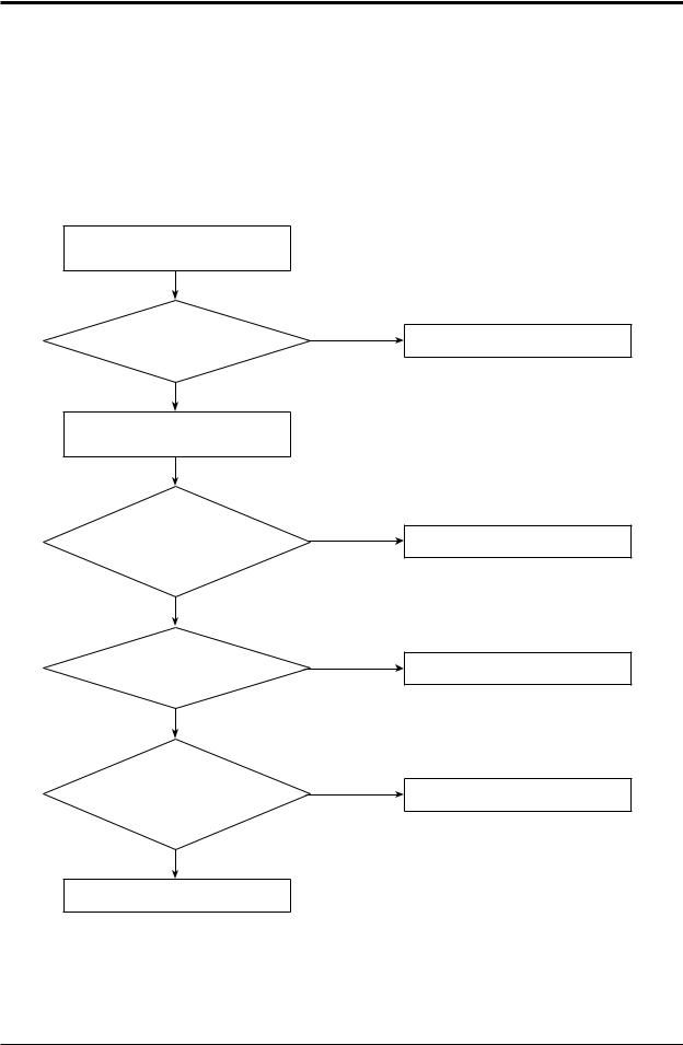
12-2-1 No Power (completely dead)-Initial diagnosis
1.Checklist:
1)Isinputvoltagenormal?
2)IsACpowerlinkedcorrectly?
3)IsinputvoltageofDCregulatorICKA7805(IC02)normal?(11VDC-12.5VDC)
4)IsoutputvoltageofDCregulatorICKA7805(IC02)normal?(4.5VDC-5.5VDC)
2.Troubleshootingprocedure
Unplugthepowercordand
plugitafter30seconds
Pressthe
PowerButtononthe remotecontrolunittooperatethe
airconditioner
doesnotoperate
Checktheindoorunit controlboard
Yes
Checkwhether
2wiresofpowercordare connectedcorrectlytothe terminalblockand controlboard.
Yes
Checkwhether
thefuseonthecontrolboardisnormal. FUSE(F701):T3.15[A]/250[V]
Yes
Checktheoutputof
SMPSonthecontrolboard.
Inputpower:AC230±15%[V]
IC02Input:DC12[V]
IC02output:DC5[V]
operate
Checkthedisplayboard
No
Reconnectwirescorrectly
No
Replacefuse
No
PCBshouldbereplaced
Yes
Checkthesettingtemperature
SamsungElectronics |
12-2 |
 Loading...