


Real Time DVR
SHR-2040/2041/2042 User’s Manual
English

-2040/2041/2042 USER’S MANUAL
Safety Regulations
Please be sure to keep the following in mind for the right use of the product to
pre-vent proprietary risk or damage.
■Do not use multiple plugs at once.
●This may cause abnormal heat generation or fire
■Do not put a vase, flowerpot, cup, cosmetics, medicine, or vessel with water around you.
●This may cause fire.
■Do not bend the power cord forcibly nor put a heavy material on it.
●This may cause fire.
■Do not touch the power plug with wet hands.
●This may cause electric shock.
■Insert the power plug firmly enough not to shake.
●This imperfect connection may cause fire.
■Keep the product off humidity, dust, or soot.
●This may cause fire or electric shock.
■Do not put metals(coin, hair pin, metal piece, etc.) or inflammable materials(match, paper, etc.) in the ventilation hole.
●This may cause fire.
■Keep the surrounding temperature between 0˚C to 40˚C and keep the product off humidity.
●This may cause breakdown.
■Secure sufficient ventilation.
●This may cause abnormal operation due to high temperature.
■Keep the product off direct ray of light or heat from the heating device
●This may cause fire.
■Do not disassemble, repair, or remodel the product.
●This may cause fire, electric shock, or injury due to abnormal operation.
■Do not pull out the power cord.
●This may destroy the power cord, eventually, cause fire or
electric shock.
■ Plug out in the event of thunder or lightning.
● This may cause fire.
■Keep your children off the battery after you take it out of the product. They tend to swallow it unconsciously.
●If your children swallow it, please see the doctor immediately.
■Install the product at a safe place or attach the product to the wall or ceiling with a stand firmly enough not to fall to the ground.
●This may injure people.
ii
Before we start
This User’s Manual describes the basic usage of SHR-2040/2041/2042.
This Manual contains all the matters necessary for using SHR-2040/2041/2042 such as brief instruction, part name, function, connecting other equipment, and menu setup of SHR-2040/2041/2042.
-SEC retains the copyright on this User’s Manual.
-This User’s Manual cannot be copied without SEC’s prior written approval.
-We are not liable for any or all losses to the product incurred by your use of non-standard product or violation of User’s Manual.
-If you want to open the system case to touch the inside, please consult with an expert who works for the shop where you bought the product.
-You may download open source codes from the following website. (See CCTV Part of http://www.samsung.com)
-Before installing any external device such as external memory or HDD, please check the compatibility of the device with Samsung DVR. The list of the compatible devices with Samsung DVR can be obtained from your vendor.
-Apparatus shall not be exposed to dripping or splashing and no objects filled with liquids, such as vases, shall be placed on the apparatus.
-The Mains plug is used as a disconnect device and shall stay readily operable at any time.
WARNING
[Battery]
As wrong exchange of the battery in SHR-2040/2041/2042 may cause explosion, you shall use the certified battery for SHR-2040/2041/2042.
The battery specification is as follows.
-Normal Voltage : 3V -Normal Capacity : 170mAh
-Continuous Standard Load : 0.2mA -Operating Temperature : -20 to +85˚C
(-4 to +185˚F)
[System Shutdown]
CALIFORNIA USA ONLY
This Perchlorate warning applies only to primary CR (Manganese Dioxide) Lithium coin cells in the product sold or distributed ONLY in California USA “Perchlorate Material - special handling may apply,
See www.dtsc.ca.gov/hazardouswaste/perchlorate.”
-Power-off without terminating the system in the System Shutdown menu may incur improper motion like data loss and disk failure. Also it can cause a dysfunction to the hard disk while using the product. Power-off shall be done in the System Shutdown menu.
[Operation warranty temperature]
-Operation warranty temperature of this device is 0°C to 45°C(32°F to 104°F) If the device is left under the warranty temperature for a long time, it cannot be operated. When using the device after leaving for a long time in the low temperature, please use it after keeping in the normal temperature for a few times. Especially the warranty temperature of the embedded HDD is 5°C to 55°C(41°F to 131°F), therefore it cannot be operated in the low temperature.
Standards Approvals
Note : This equipment has been tested and found to comply with the limits for a Class A digital device, pursuant to part 15 of the FCC Rules.
These limits are designed to provide reasonable protection against harmful interference when the equipment is operated in a commercial environment. This equipment generates, uses, and can radiate radio frequency energy and, if not installed and used in accordance whit the instruction manual, may cause harmful interference to radio communications. Operation of this equipment in a residential area is likely to cause harmful interference in which case the user will be required to correct the interference at his own expense.
English iii

Contents
iiSafety Regulations Before we start Standards Approvals
|
Chapter 1 Overview |
|
1-1 |
1. |
Introduction |
1-2 |
2. |
Features |
1-3 |
3. |
Part Names and Functions |
2 |
Chapter 2 Installation |
|
2-1 |
1. |
Installation Environment Setup |
2-3 |
2. |
Checking Product & Accessory |
2-4 |
3. |
HDD Addition |
3 |
Chapter 3 Connecting with other device |
|
3-1 |
1. |
Connecting the Video, Audio, and Monitor |
|
||
3-3 |
2. |
Connecting the Network |
|
||
3-5 |
3. |
Connecting the USB |
|
||
3-6 |
4. |
Connecting the Alarm Input/Output |
|
||
3-8 |
5. |
Connecting the RS-485 Device |
|
||
4 |
Chapter 4 Live |
|
4-1 |
1. |
System Operation |
4-2 |
2. |
Live Screen Mode |
4-5 |
3. |
Live Channel Selection and Audio On/Off Setup |
4-6 |
4. |
Freeze and Zoom |
4-7 |
5. |
Event Monitoring |
4-8 |
6. |
Spot-out Monitoring |
iv

5 |
|
Menu Setup |
5-1 |
Before Use |
|
5-2 |
1. |
System |
5-14 |
2. |
Camera |
5-18 |
3. |
Monitoring |
5-20 |
4. |
Recording Mode |
5-22 |
5. |
Event Record Mode |
5-27 |
6. |
Schedule |
5-29 |
7. |
Backup |
5-30 |
8. |
Network |
5-34 |
9. |
Network Setup |
6 |
Chapter 6 PTZ Camera Control |
|
6-1 |
1. |
PTZ Camera Control Mode |
6-3 |
2. |
Basic Operation of PAN, TILT, & ZOOM |
6-4 |
3. |
Preset Setup |
6-6 |
4. |
Camera Menu Setup |
6-7 |
5. |
Preset View |
6-8 |
6. |
Other View |
7 |
Chapter 7 Recording |
|
7-1 |
1. |
REC (Normal Recording) |
7-2 |
2. |
Schedule Recording |
7-3 |
3. |
Event Recording |
8 |
Chapter 8 Search and Play |
|
8-1 |
Before Use |
|
8-2 |
1. |
Calendar Search |
8-3 |
2. |
Event Search |
8-4 |
3. |
Date/Time Search |
8-5 |
4. |
Go to First Search |
8-6 |
5. |
Go to Last Search |
8-7 |
6. |
Backup |
8-8 |
7. |
Playback |
English v

9 |
|
|
9-1 |
1. |
Introduction |
9-2 |
2. |
Feature |
9-3 |
3. |
PC Specification(Recommendation) |
9-4 |
4. |
Smart Viewer Installation |
9-7 |
5. |
Smart Viewer Program Execution |
9-8 |
6. |
Smart Viewer Initial Screen |
9-9 |
7. |
Monitoring Mode |
9-23 |
8. |
Search Mode |
9-30 |
9. |
Setup Mode |
10 |
Appendix |
|
10-1 |
1. |
Product Specification |
10-4 |
2. |
Outline Drawings |
10-6 |
3. |
Factory Default |
10-9 |
4. |
SHR-2040/2041/2042 Smart Viewer |
|
|
Frame Specification for the Playback |
10-11 |
5. Troubleshooting(FAQ) |
|
10-14 |
6. |
Open source license report on the product |
vi

Chapter 1
Overview

SHR-2040/2041/2042 USER’S MANUAL
The Digital Video Recorder(DVR) compresses the 4 channel of camera input data into the MPEG4 video file and the 4 channel of voice input data into the ADPCM audio file in the real time to record them in the Hard Disk or retrieve them from the Hard Disk simultaneously.
In addition, it transfers the Video/Audio out through a network in the real time and it is able to monitor the Video/Audio remotely by your PC.
1-1 English

2Features
■4 CH Composite Input Connectors
■NTSC / PAL Video Source Compatible
( NTSC : SHR-2040 / SHR-2041 / SHR2042, SHR-2040N / SHR-2041N / SHR-2042N
PAL : SHR-2040P / SHR-2041P / SHR2042P )
■Able to record the CIF sized (NTSC-352 x 240 / PAL-352 x 288) video at the speed of 120 ips(NTSC)/100ips(PAL)(Image Per Second)
■4 CH Loop Through Video Connectors
■Hard Disk Overwrite Mode
■Large Quantity Hard Disk Backup by USB2.0
■Backup function by the USB2.0 memory and exterior CD/DVD writer (SHR-2042 supports the internal CD-RW.)
■Able to record, play, and transmit both audio and video files to Windows Network Viewer(Smart Viewer) simultaneously
■Able to record and play the audio 4CH
■Variable Search Mode (Time/Date, Event, Schedule)
■Variable Recording Mode (Time Lapse, Event, Schedule)
■Extended Hard Disk Connection (USB2.0)
■Alarm Interface function (Input : 4, Output : 2, Reset : 1)
■Remote Monitoring function by Windows Network Viewer(Smart Viewer)
English 1-2
SHR-2040/2041/2042 USER’S MANUAL
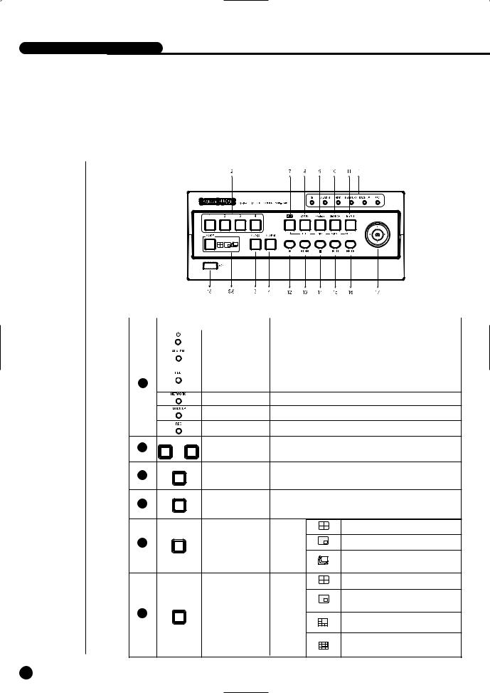
3Part Names and Functions
|
|
[SHR-2040] |
|
|
|
|
Name |
Function |
|
Power LED |
Displays power on/off condition. |
|
|
|
|
Alarm LED |
lights on when an event occurs. |
|
|
|
|
HDD Access |
Displays Normal Access to HDD. Upon Access to HDD, LED |
Network LED Displays both network connection and data transmission conditions.
|
Backup LED |
Displays Back Up Mode. |
||
|
Rec LED |
Displays the record condition. |
||
1 |
4 |
Selects a channel in the Single Mode. Used for number |
||
... |
Channel Button |
|||
input button in the number input mode. |
||||
AUDIO |
Audio Setup |
|
|
|
|
Sets the Audio On/Off. |
|
||
|
Button |
|
||
|
|
|
||
ALARM |
Setup |
|
|
|
4 |
Cancels the alarm when the Alarm button is selected. |
|||
|
||||
|
|
|
Displays 4 split screen. |
|
MODE |
Split Screen |
Display |
|
|
|
Displays PIP(Picture in Picture) screen. |
|||
|
Selection Button |
Mode |
The single channel screen is changed |
|
|
|
|
||
|
|
|
according to the time set on the menu. |
|
|
|
|
Displays 4 split screen. |
|
|
|
|
Displays both LIVE Channel and Playback |
|
MODE |
Mode Selection |
|
Channel in the PIP Screen simultaneously. |
|
6 |
Search |
Displays 6 split screen. |
||
Button |
||||
|
|
|||
|
|
|
(1 CH playback screen and 4 CH live screen) |
|
|
|
|
Displays 9 split screen. |
|
|
|
|
(4 CH playback screen and 4 CH live screen) |
|
1-3
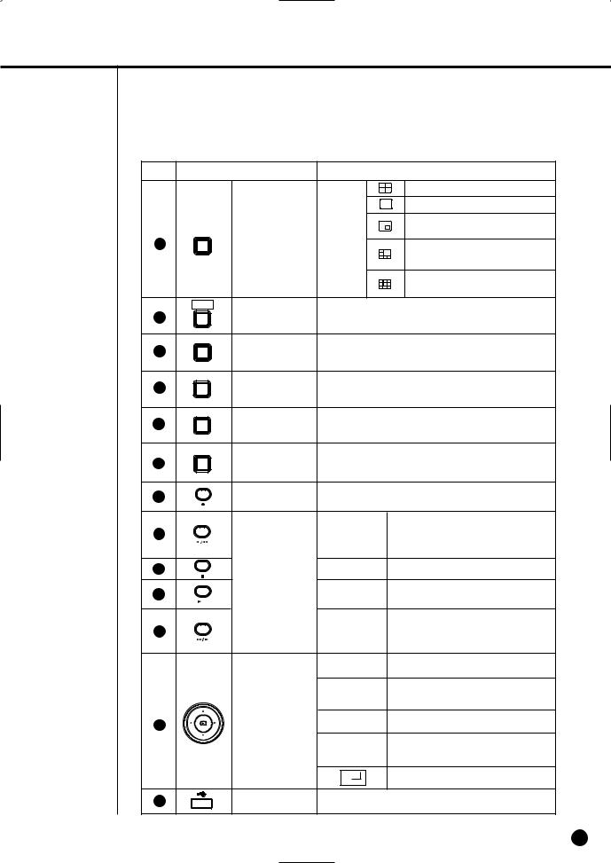
No. |
|
Name |
|
Function |
|
PTZ |
|
|
|
7 |
|
|
TELE, WIDE, PRESET, and VIEW function. |
|
|
ZOOM |
ZOOM(TELE) |
Sets up Digital Zoom(x2). |
|
|
|
|||
|
TELE |
|
|
the PTZ button.) |
|
|
|
|
|
|
FREEZE |
FREEZE(WIDE) |
Performs the FREEZE function in the DISPLAY Mode. |
|
|
|
|||
|
WIDE |
Button |
( Performs the WIDE function by pressing the PTZ button.) |
|
|
|
|
|
|
|
SEARCH |
SEARCH(VIEW) |
Displays the search method. |
|
|
|
|||
|
VIEW |
Button |
( Performs the VIEW function by pressing the PTZ button.) |
|
|
|
|
|
|
|
MENU |
MENU (PRESET) |
Displays the system setup menu or enters to the upper |
|
|
|
menu.( Performs the PRESET setup function by pressing |
||
|
|
Button |
||
|
PRESET |
the PTZ.) |
|
|
|
|
|
||
|
|
RECORD |
Records the record setup set in the normal record mode. |
|
|
|
|
Fast/Step |
Fast Reverse: Used for the fast rewinding |
|
|
|
search in the playback mode. |
|
|
|
|
Reverse |
Step Reverse: Used for the 1 step reverse |
|
|
|
|
search during the pause. |
|
|
Search Function |
STOP |
Used for the search stop in the playback mode. |
|
|
Key |
PLAY/PAUSE |
Toggles in the playback mode to activate |
|
|
|
||
|
|
|
|
PLAY/PAUSE. |
|
|
|
Fast/Step |
Fast Forward: Used for the fast-forwarding |
|
|
|
search in the playback mode. |
|
|
|
|
Forward |
Step Forward: Used for the 1 step-forwarding |
|
|
|
|
search during the pause. |
|
|
|
|
In case of setting the details of Menu, it is |
|
|
|
used as Direction Key. (For PTZ Operation) |
|
|
|
|
|
In case of setting the details of Menu, it |
|
|
|
increases the value or it is used as Direction |
|
|
|
|
|
Key. (For PTZ Operation) |
17 |
|
Direction Button |
|
In case of setting the details of Menu, it is |
|
Key |
used as Direction Key. (For PTZ Operation) |
||
|
|
|
In case of setting the details of Menu, it |
|
|
|
|
|
|
|
|
|
decreases the value or it is used as Direction |
|
|
|
|
|
Key. (For PTZ Operation) |
|
|
|
|
Acts as the Enter key for the menu setup. |
18 |
|
USB Port |
Connects the USB type device. |
|
English 1-4

-2040/2041/2042 USER’S MANUAL
[SHR-2041]
|
|
|
[SHR-2042] |
|
|
No. |
|
Name |
|
Function |
|
|
|
Power LED |
Displays power on/off condition. |
||
|
|
Alarm LED |
lights on when an event occurs. |
||
|
|
HDD Access |
Displays Normal Access to HDD. Upon Access to HDD, LED |
||
1 |
|
|
|
|
|
|
|
Network LED |
Displays both network connection and data transmission conditions. |
||
|
|
Backup LED |
Displays Back Up Mode. |
||
|
|
Rec LED |
Displays the record condition. |
||
2 |
|
Eject Button |
Performs the OPEN/CLOSE of CD/RW. |
||
1 |
|
4 |
Selects a channel in the Single Mode. Used for number |
||
3 |
... |
Channel Button |
|||
input button in the number input mode. |
|||||
|
|
|
|||
4 |
AUDIO |
Setup |
|
|
|
|
|
Sets the Audio On/Off. |
|
||
|
ALARM |
Alarm Setup |
Turns off the alarm LED and stops the sound when an |
||
|
|
|
|||
|
|
alarm is issued. |
|
||
|
|
Button |
|
||
|
|
Alarm icon disappears when the alarm button is used. |
|||
|
|
|
|||
|
|
|
|
Displays 4 split screen. |
|
|
MODE |
Split Screen |
Display |
Displays PIP(Picture in Picture) screen. |
|
6 |
|
||||
|
Selection Button |
Mode |
|
||
|
|
Auto Sequence Mode: The single channel screen |
|||
|
|
|
|
||
|
|
|
|
is changed according to the time set on the menu. |
|
1-5
No. |
|
Name |
|
Function |
|
|
|
|
Displays 4 split screen. |
|
|
|
|
Displays the selected channel to the Single Mode |
|
|
|
|
Displays both LIVE Channel and Playback |
|
MODE |
Mode Selection |
|
Channel in the PIP Screen simultaneously. |
7 |
|
|
|
|
|
|
|
Displays 6 split screen. |
|
|
|
|
|
|
|
|
|
|
(1 CH playback screen and 4 CH live screen) |
|
|
|
|
Displays 9 split screen. |
|
|
|
|
(4 CH playback screen and 4 CH live screen) |
|
PTZ |
|
|
|
|
|
|
|
VIEW function. |
|
ZOOM |
ZOOM(TELE) |
Sets up Digital Zoom(x2). |
|
|
|
|||
|
TELE |
Button |
( Performs the TELE function by pressing the PTZ button.) |
|
|
|
|
|
|
|
FREEZE |
FREEZE(WIDE) |
Performs the FREEZE function in the DISPLAY Mode. |
|
|
|
|||
|
WIDE |
Button |
( Performs the WIDE function by pressing the PTZ button.) |
|
|
|
|
|
|
|
SEARCH |
SEARCH(VIEW) |
Displays the search method.( Performs the VIEW function |
|
|
|
|||
|
VIEW |
Button |
by pressing the PTZ button.) |
|
|
|
|
|
|
|
MENU |
MENU (PRESET) |
Displays the system setup menu or enters to the upper |
|
|
|
menu.( Performs the PRESET setup function by pressing |
||
|
|
Button |
||
|
PRESET |
the PTZ.) |
|
|
|
|
|
|
|
|
|
RECORD |
Records the record setup set in the normal record mode. |
|
|
|
|
Fast/Step |
Fast Reverse: Used for the fast rewinding |
|
|
|
search in the playback mode. |
|
|
|
|
Reverse |
Step Reverse: Used for the 1 step reverse |
|
|
|
|
search during the pause. |
|
|
Search Function |
STOP |
Used for the search stop in the playback mode. |
|
|
|
Toggles in the playback mode to activate |
|
|
|
Key |
PLAY/PAUSE |
|
|
|
PLAY/PAUSE. |
||
|
|
|
Fast / Step |
Fast Forward: Used for the fast-forwarding |
|
|
|
search in the playback mode. |
|
|
|
|
Forward |
Step Forward: Used for the 1 step-forwarding |
|
|
|
|
search during the pause. |
|
|
|
|
In case of setting the details of Menu, it is |
|
|
|
used as Direction Key. (For PTZ Operation) |
|
|
|
|
|
In case of setting the details of Menu, it |
|
|
|
increases the value or it is used as |
|
|
|
Direction Button |
|
Direction Key. (For PTZ Operation) |
18 |
|
|
In case of setting the details of Menu, it is |
|
|
Key |
used as Direction Key. (For PTZ Operation) |
||
|
|
|||
|
|
|
|
In case of setting the details of Menu, it |
|
|
|
decreases the value or it is used as |
|
|
|
|
|
Direction Key. (For PTZ Operation) |
|
|
|
|
Acts as the Enter key for the menu setup. |
19 |
|
USB Port |
Connects the USB type device. |
|
English 1-6

-2040/2041/2042 USER’S MANUAL
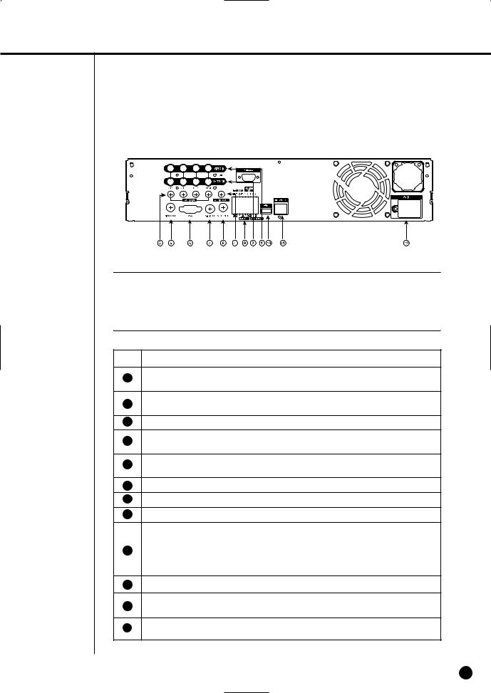
[SHR-2040]
 Caution
Do not play DVR on the carpet or other soft material to prevent clogging of the air ventilator. To play DVR on the cabinet or rack, be sure to check the ventilation condition.
No. |
Name |
Function |
|
|
|
|
|
1 |
VIDEO IN |
Composite Video Signal Input Port (BNC Style Connector) |
|
|
|
|
|
2 |
THROUGH |
You may use THROUGH port to transmit a video signal to the |
|
other video equipment. |
|||
|
|
||
|
|
|
|
3 |
AUDIO IN |
Audio Signal Input Port (RCA Jack) |
|
4 |
AUDIO OUT |
Audio Signal Output Port (RCA Jack) |
|
|
|
|
|
|
OUT |
Composite Video Signal Output Port (BNC Style Connector) |
|
|
|
|
|
|
VGA |
VGA Video Signal Output Port |
|
|
|
|
|
|
S-VIDEO |
S-VIDEO Video Signal Output Port |
|
|
|
|
|
|
SPOT OUT |
SPOT Out Output Port (BNC Style Connector) |
|
|
|
|
|
|
|
- ALARM IN 1~4 : Alarm Input Port |
|
|
ALARM |
- ALARM RESET IN : Alarm Reset Port |
|
|
|
- ALARM OUT1~2 : Alarm Output Port |
|
|
|
- TX+, TX-, RX+, RX- : RS-485 Communication |
|
|
|
|
|
|
USB |
USB connection Port |
|
|
|
|
|
|
NETWORK |
Network Connection Port |
|
|
|
|
|
|
DC-IN |
12V Power Socket Support |
|
|
|
|
1-7
[SHR-2041/2042]
 Caution
Do not play DVR on the carpet or other soft material to prevent clogging of the air ventilator. To play DVR on the cabinet or rack, be sure to check the ventilation condition.
No.
1
2
3
4
Name |
Function |
|
VIDEO IN |
Composite Video Signal Input Port (BNC Style Connector) |
|
THROUGH |
You may use THROUGH port to transmit a video signal to the |
|
other video equipment. |
||
|
||
AUDIO IN |
Audio Signal Input Port (RCA Jack) |
|
AUDIO OUT |
Audio Signal Output Port (RCA Jack) |
|
OUT |
Composite Video Signal Output Port (BNC Style Connector) |
|
VGA |
VGA Video Signal Output Port |
|
S-VIDEO |
S-VIDEO Video Signal Output Port |
|
SPOT OUT |
SPOT Out Output Port (BNC Style Connector) |
|
|
- ALARM IN 1~4 : Alarm Input Port |
|
ALARM |
- ALARM RESET IN : Alarm Reset Port |
|
|
- ALARM OUT1~2 : Alarm Output Port |
|
|
- TX+, TX-, RX+, RX- : RS-485 Communication |
|
USB |
USB connection Port |
|
NETWORK |
Network Connection Port |
|
AC-IN |
(NTSC) AC 110~220V Power Socket Support |
|
(PAL) AC 100~230V Power Socket Support |
||
|
||
|
|
English 1-8


Chapter 2
Installation
SHR-2040/2041/2042 USER’S MANUAL
Environment Setup
the carpet or other soft material to prevent clogging of the air ventilator. cabinet or rack, be sure to check the ventilation condition.
to the following before you use the product.
.
or liquid in the connection part or the product itself. excessive shock or force.
power plug unreasonably. the product on your own. rated input or output range.
cord only.
with a ground for the product with an input ground.
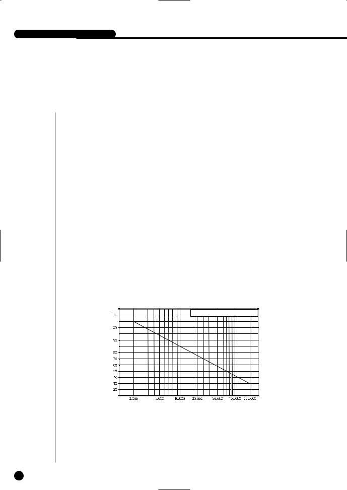
Samsung Digital Video Recorder (hereafter “DVR”) is a high-tech security equipment that contains a high-capacity HDD and top-notch circuits. High temperature inside or outside of the product may cause reduced life and deteriorated performance (see graph 1 below), leading to a malfunction. So please follow the instructions below to proceed with the installation.
Temperature |
One Year:24 HR X 365 DAY = 8,760 HR |
|
(Unit:°C) |
||
|
||
|
Life (Unit:HOURS) |
<Graph 1 : Correlation between temperature and product life>
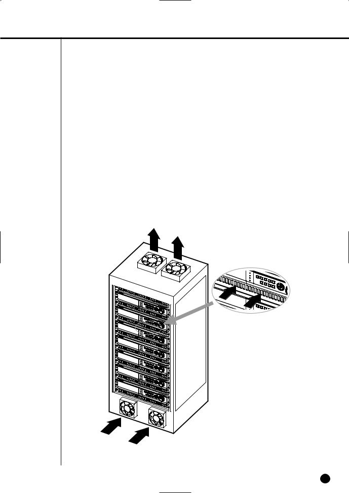
<Instructions for the rack mounting of Samsung DVR>
1.The rack on which the DVR is mounted should not be sealed off.
2.And it also can allow air circulation through the vent.
3.As in the figure to the right, we recommend the product should be stacked up with other DVRs or rack-mounting devices at a certain space or you install a vent system to accommodate airflow.
4.For forming a natural convection, the air intake hole should be positioned at the bottom and the emission at the top.
5.We recommend you install each of the air intake and emission holes with a fan motor for sufficient airflow.
(The air intake fan should be equipped with a filter to block dust and other impurities from inflow.)
6.The temperature inside the rack and around the DVR should stay between 0°C and 40°C (32°F and 104°F).
English 2-2

-2040/2041/2042 USER’S MANUAL
2Checking Product & Accessory
Upon delivery of a product, you shall unwrap the product and put it on the even floor or where you want to use it. Then you shall check if the following items are in it.
■Main Body
■User’s Manual
■One Power Cord
■Two Brackets
-These are not supplied in SHR-2040.
-Brackets are used to attach the product to the rack.
■Smart Viewer Software CD (PDF Manual included)
■Special Screws
-SHR-2041 : SCREW-SPECIAL 12EA
-SHR-2042 : SCREW-SPECIAL 4EA
-SHR-2040 : SCREW 4EA (Code : 6001-000742)
-Please keep special screws for HDD addition.
■2 EA of RS-485/Alarm Terminal Block
Main Body
SHR-2040
Main Body
SHR-2041
Main Body
SHR-2042
CD Bracket
Power Cord
|
|
RS-485/Alarm |
User’s Manual |
Screw |
Terminal Block |
Adapter (Only 2040)
WARNING) SHR-2040 set must use the adapter we provide. Adapter : ADP-5412
2-3 English
3HDD Addition
 Caution
[Checking HDD Data]
Please, pay attention to Following information to minimize the chance of losing HDD data.
-Remember that you should protect HDD from any impact or misuse as this may cause damaged.
-The Manufacturer is not responsible for missing data or defects caused by the user’s mishandling.
Note: Adding Extra HDD. Check in advance that the HDD is compatible with the manufacturer’s DVR.
Examples that can cause loss of data or damage HDD.
-Any outside Impact on the case which could happen whilst disassembling or setting up the DVR.
-Power cut or incorrect shutdown whilst the DVR is operating.
-Refer to page 5-11 : how to turn off DVR
-Moving or causing any impact on the DVR during operation. Please, back up events as soon as possible to minimize disappointment should HDD data be lost.
SHR-2040 HDD ADDITION
The user can add 1 HDD to this product. However, there are many factors that can cause electrical shock, accidents, and malfunctioning of the device inside of the product. When the user does not correctly install or apply the proper settings, the device may not recognize the HDD or the device will not run. Therefore, before adding any HDDs, it is recommended that the user contacts a specialist where they purchased the product.
[Caution when adding a HDD]
■When adding HDDs, pay attention so that the cable doesn’t get caught between unsuitable places or the cable’s insulation doesn’t come off. (This may cause a malfunction or fire.)
■When adding HDDs, be careful not to receive any injury from the pointed edges inside the product.
■Pay attention so as not to lose the disassembled screws or accessories.
If the screws or accessories are not put together, the product will either malfunction or won’t be able to operate.
■Check the compatibility list of HDDs before installing additional HDDs. The list of the compatible devices with Samsung DVR can be obtained from your vendor.
■If you contact the RTC battery while adding hard disks, the battery failure may happen. In this case, you will encounter failures when setting the time and operating DVR.
■If you don’t connect fan power cables after adding hard disks, the fan failure message appears on the screen. This can cause operation failures because it raises the temperature inside your DVR.
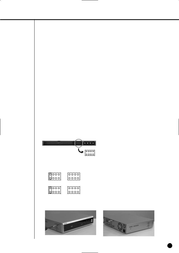
[Setting the Jumper]
The jumper setting method is illustrated on the surface of the purchased HDD. Using SAMSUNG hard disk, the jumper setting method is as follows:
• HDD jumper for Primary Master and Primary Slave.
English 2-4
-2040/2041/2042 USER’S MANUAL
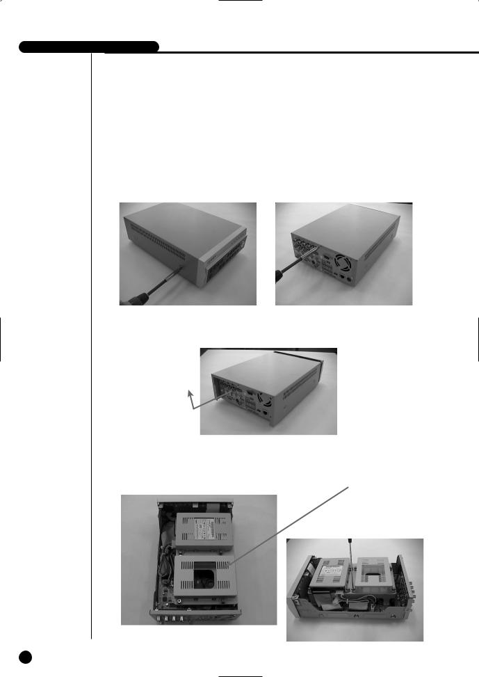
[How to Add a HDD]
1.To remove the product’s cover, take out the screws on the left and right sides (2 spots each) and on the back (3 spots).
2.Remove the cover from the product. (Remove the cover by first lifting its back part upward after sliding the cover slightly backward.)
3.There is bracket-HDD mounted on the back where you can mount a HDD, and you have to remove the screws (4 spots) that are holding the bracket that you want to mount an HDD onto.
BRACKET-HDD
2-5 English
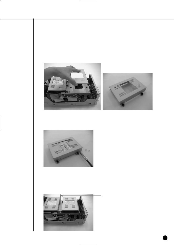
4. Remove the bracket-HDD from the product by lifting it upward from the product.
5.Mount the HDD to the bracket-HDD with the SCREW-TAPTITE (BW, +, S, M3, L6, ZPC) (4 spots) that was provided as an accessory. (The screws have to be tightened so that it doesn’t vibrate loose.)
6.Re-mount the built-in HDD bracket-HDD to the place where it was separated from.
The work order for mounting the BRACKET-HDD is in reverse from when disassembling it. Tighten the screw after the BRACKET-HDD’s mounting holes are perfectly aligned with four mounting spots on the bottom.)
SCREWDRIVER
English 2-6
-2040/2041/2042 USER’S MANUAL
7.Make sure that the bracket-HDD is mounted stably inside the product, then connect the power supply cable and signal transmission cable (IDE cable) to the HDD.
8.Check if there is any problem with connector or wiring inside of the product for connecting and mounting then close the cover.
9.Tighten cover mounting screws. (The left and right side each has 2 spots and the back side has 3 spots)
2-7 English

SHR-2041 HDD ADDITION
The user can add 3 HDDs to this product.
However, there are many factors that can cause electrical shock, accidents, and malfunctioning of the device inside of the product. When the user does not correctly install or apply the proper settings, the device may not recognize the HDD or the device will not run. Therefore, before adding any HDDs, it is recommended that the user contacts a specialist where you purchased the product.
[Caution when adding a HDD]
■When adding HDDs, pay attention so that the cable doesn’t get caught between unsuitable places or the cable’s insulation doesn’t come off. (This may cause a malfunction or fire.)
■When adding HDDs, be careful not to receive any injury from the pointed edges inside the product.
■Pay attention so as not to lose the disassembled screws or accessories.
If the screws or accessories are not put together, the product will either malfunction or will be inop erable.
■Check the compatibility list of HDDs before installing additional HDDs. The list of the compatible devices with Samsung DVR can be obtained from your vendor.
■If you contact the RTC battery while adding hard disks, the battery failure may happen. In this case, you will encounter failures when setting the time and operating DVR.
■If you don’t connect fan power cables after adding hard disks, the fan failure message appears on the screen. This can cause operation failures because it raises the temperature inside your DVR.
[Setting the Jumper]
The jumper setting method is illustrated on the surface of the purchased HDD. Using SAMSUNG hard disk, the jumper setting method is as follows:
•HDD jumper for Primary Master and Primary Slave.
•Jumper setting for Secondary Master and Secondary Slave.
[How to Add a HDD]
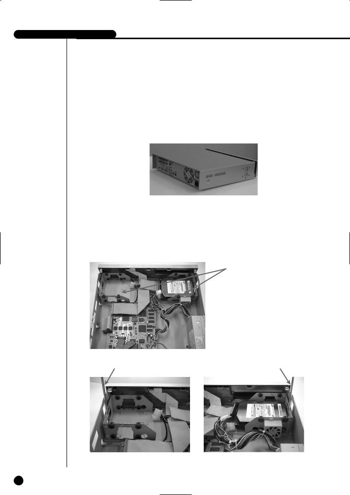
1.To remove the product’s cover, take out the screws on the left and right sides (5 spots each) and on the back (1 spot).
English 2-8
-2040/2041/2042 USER’S MANUAL
2.Remove the cover from the product. (Remove the cover by first lifting its back part upward after sliding the cover slightly backward.)
3.There is a bracket (bracket-HDD) mounted on the right and left sides where you can mount the HDD, and you have to remove the screws that are holding the bracket that you want to mount an HDD onto.
BRACKET-HDD
SCREWDRIVER |
SCREWDRIVER |
2-9 English

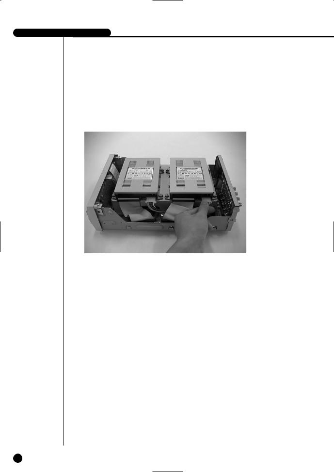
4.Remove the bracket-HDD from the product by separating the power supply cable, signal transmission cable (IDE cable), and fan cable then pulling it toward the center of the product to separate its fixed part from the bottom.
5.Mount the HDD to the bracket-HDD with the SCREW-SPECIAL (BWH, 6-32UNC, L10.5) (4 spots) that was provided as an accessory. (The screws have to be tightened so that it doesn’t vibrate loose.)
English 2-10

-2040/2041/2042 USER’S MANUAL
6.Re-mount the built-in HDD bracket-HDD to the place where it was separated from.
Place the bracket-HDD so that all five mounting spots on the bottom and the bracket-HDD’s mounting holes are perfectly aligned, then slide it toward the outside of the product and tigh ten the screws.
7.Make sure that the bracket-HDD is mounted stably inside of the product, then connect the power supply cable, signal transmission cable (IDE cable), and fan cable to the HDD.
MASTER HDD
SLAVE HDD
8.Check if there is any problem with connector or wiring inside of the product for connecting and mounting then close the cover.
9.Tighten cover mounting screws. (The left and right side each has 5 spots and the back side has 1 spot)
 Caution
When mounting an additional HDD, the primary master has to be mounted.
2-11 English
SHR-2042 HDD ADDITION
The user can add up to 2 HDDs to this product.
However, there are many factors that can cause electrical shock, accidents, and malfunctioning of the device inside of the product. When the user does not correctly install or apply the proper settings, the device may not recognize the HDD or the device will not run. Therefore, before adding any HDDs, it is recommended that the user contacts a specialist where they purchased the product.
[Caution when adding a HDD]
■When adding HDDs, pay attention so that the cable doesn’t get caught between unsuitable places or the cable’s insulation doesn’t come off. (This may cause a malfunction or fire.)
■When adding HDDs, be careful not to receive any injury from the pointed edges inside the product.
■Pay attention so as not to lose the disassembled screws or accessories.
If the screws or accessories are not put together, the product will either malfunction or will be inop erable.
■Check the compatibility list of HDDs before installing additional HDDs. The list of the compatible devices with Samsung DVR can be obtained from your vendor.
■If you contact the RTC battery while adding hard disks, the battery failure may happen. In this case, you will encounter failures when setting the time and operating DVR.
■If you don’t connect fan power cables after adding hard disks, the fan failure message appears on the screen. This can cause operation failures because it raises the temperature inside your DVR.
[Setting the Jumper]
The jumper setting method is illustrated on the surface of the purchased HDD. Using SAMSUNG hard disk, the jumper setting method is as follows:
•HDD jumper for Primary Master and Primary Slave.
•Jumper setting for Secondary Master (CD-RW) and Secondary Slave.
[How to Add a HDD]
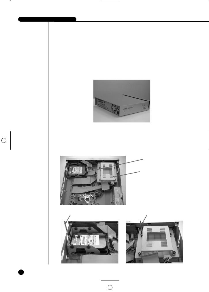
1.To remove the product’s cover, take out the screws on the left and right sides (5 spots each) and on the back (1 spot).
English 2-12
-2040/2041/2042 USER’S MANUAL
2.Remove the cover from the product. (Remove the cover by first lifting its back part upward after sliding the cover slightly backward.)
3.There is a bracket (bracket-HDD) mounted on the right and left sides where you can mount the HDD, and you have to remove the screws that are holding the bracket that you want to mount an HDD onto.
BRACKET-HDD(A)
BRACKET-HDD(B)
SCREWDRIVER |
SCREWDRIVER |
2-13 English
 Loading...