


 Loading...
manual user DVR Channel 8/16
Correct Disposal of This Product(Waste Electrical & Electronic Equipment)
(Applicable in the European Union and other European countries with separate collection systems)
This marking shown on the product or its literature, indicates that it should not be disposed with other household wastes at the end of its working life. To prevent possible harm to the environment or human health from uncontrolled waste disposal, please separate this from other types of wastes and recycle it responsibly to promote the sustainable reuse of material resources.
Household users should contact either the retailer where they purchased this product, or their local government office, for details of where and how they can take this item for environmentally safe recycling.
Business users should contact their supplier and check the terms and conditions of the purchase contract. This product should not be mixed with other commercial wastes for disposal.
SHR-5080/5082
SHR-5160/5162
8/16 Channel DVR
user manual
imagine the possibilities
Thank you for purchasing a Samsung product. To receive a more complete service, please
register your product at
www.samsung.com/global/register
Code No. AB68-00686B-02
key features of your DVR
The Digital Video Recorder (DVR) compresses the acquired images of 8/16 video channels from cameras using MPEG-4 technologies, and compresses the 4 channel audio inputs into ADPCM audio file to record them on the hard disk or retrieve them from the hard disk simultaneously.
In addition, it transfers the video and audio data through a network and allows you to remotely monitor them using your PC.
8/16 channel Composite Input connectors
NTSC/PAL video source compatible
With Dual Codec, can change the FPS (frames per second) according to the bandwidth and send live pictures regardless of the recording condition
Picture quality improvement by adopting the De-interlace chip
Can display HDD information and status using the HDD SMART function
Can convert the CIF (NTSC: 352*240, PAL: 352*288) images to 120 IPS images for NTSC or 100 IPS images for PAL
8/16 channel loop through video connectors
Hard disk overwrite mode
USB 2.0 hard disk backup capability for large quantities of data
Backup function using USB 2.0 memory and external CD/DVD writer (SHR-5162 and SHR-5082 include built-in DVD writer)
Can record, play, and transmit audio/video data to Windows Network Viewer (Smart Viewer) simultaneously
Can record or play 8/16 channel video data
Various search modes (time/date, event, schedule)
Various recording modes (time lapse, event, schedule)
Extended hard disk connection (USB 2.0)
Alarm interface function (Input: 8/16, Output: 4, Reset: 1)
Remote monitoring function using Windows Network Viewer (Smart Viewer)
WHAT’S INCLUDED WITH YOUR DVR
Upon delivery of this product, you shall unwrap and put it on the even floor or where you want to use it. Then you must check if the following items are in it.
Remote control unit |
One power cord |
Two brackets |
Smart Viewer |
(RCU) |
|
Brackets are used to |
software CD (PDF |
|
|
attach the product to the |
manual included) |
|
|
rack |
|
|
|
|
|
Special 4 screws |
2 EA of RS-485/ |
2 EA of AAA batteries |
User manual |
|
Alarm terminal block |
|
|
|
|
|
|
safety regulations
Please be sure to keep the following in mind for the right use of the product to prevent proprietary risk or damage.
Do not use multiple plugs at once.
This may cause abnormal heat generation or fire
Do not put a vase, flowerpot, cup, cosmetics, medicine, or vessel with water around you.
This may cause fire.
Do not bend the power cord forcibly nor put a heavy material on it.
This may cause fire.
Do not touch the power plug with wet hands.
This may cause electric shock.
Insert the power plug firmly enough not to shake.
This imperfect connection may cause fire.
Keep the product off humidity, dust, or soot.
This may cause fire or electric shock.
Do not put metals (coin, hair pin, metal piece, etc.) or inflammable materials (match, paper, etc.) in the ventilation hole.
This may cause fire.
Keep the surrounding temperature between 0°C to 40°C and keep the product off humidity.
This may cause breakdown.
Secure sufficient ventilation.
This may cause abnormal operation due to high temperature.
Keep the product off direct ray of light or heat from the heating device.
This may cause fire.
Do not disassemble, repair, or remodel the product.
This may cause fire, electric shock, or injury due to abnormal operation.
Do not pull out the power cord.
This may destroy the power cord, eventually, cause fire or electric shock.
Plug out in the event of thunder or lightning.
This may cause fire.
Keep your children off the battery after you take it out of the product. They tend to swallow it unconsciously.
If your children swallow it, please see the doctor immediately.
Install the product at a safe place or attach the product to the wall or ceiling with a stand firmly enough not to fall to the ground.
This may injure people.

before start
This user’s manual provides Information for using DVR such as brief introduction, part names,
functions, connection to other equipment, menu setup, and the like. You have to keep in mind the following notices:
SEC retains the copyright on this manual.
This manual cannot be copied without SEC’s prior written approval.
We are not liable for any or all losses to the product incurred by your use of non-standard product or violation of instructions mentioned in this manual.
If you want to open the case of your system for checking problems, please consult the expert from the shop where you bought the product.
You may download open source codes from the following website: http://www.samsung.com.
Before installing any external device such as external memory or HDD, please check the compatibility of the device with Samsung DVR. The list of the compatible devices with Samsung DVR can be obtained from your vendor.
Apparatus shall not be exposed to dripping or splashing and no objects filled with liquids, such as vases, shall be placed on the apparatus.
The Mains plug is used as a disconnect device and shall stay readily operable at any time.
WARNING
Battery
Exchanging a wrong battery in your product may cause an explosion. Therefore you must use the same type of battery as the one being used in the product.
The following are the specifications of the battery you are using now.
Normal voltage: 3V
Normal capacity: 170mAh
Continuous standard load: 0.2mA
Operating temperature: -20°C ~ +85°C
(-4°F ~ +185°F)
CALIFORNIA USA ONLY
This Perchlorate warning applies only to primary CR (Manganese Dioxide) Lithium coin cells in the product sold or distributed ONLY in California USA.
“Perchlorate Material - special handling may apply, See www.dtsc.ca.gov/hazardouswaste/perchlorate.”
System Shutdown
Turning off the power while the product is in operation, or taking not permitted actions may cause damage to the hard drive or the product. Also it can cause a dysfunction to the hard disk while using the product. Please turn off the power using the Power button on the front of your DVR. After selecting OK in the pop-up menu, you can pull off the power cord.
You may want to install a UPS system for safe operation in order to prevent damage caused by an unexpected power stoppage. (Any questions concerning UPS, consult your USP retailer.)
Operating Temperature
The guaranteed operating temperature range of this product is 0°C ~ 40°C (32°F ~ 104°F).
This product may not work properly if you run right after a long period of storage at a temperature below the guaranteed one.
When using the device after a long period of storage at low temperature, place the product at room temperature for a while and run it.
Especially for the built-in HDD in the product, its guaranteed temperature range is 5°C ~ 55°C (41°F ~ 131°F). Likewise, the hard drive may not work at a temperature below the guaranteed one.
STANDARDS APPROVALS
This equipment has been tested and found to comply with the limits for a Class A digital device, pursuant to part 15 of the FCC Rules. These limits are designed to provide reasonable protection against harmful interference when the equipment is operated in a commercial environment.
This equipment generates, uses, and can radiate radio frequency energy and, if not installed and used in accordance with the instruction manual, may cause harmful interference to radio communications. Operation of this equipment in a residential area is likely to cause harmful interference in which case the user will be required to correct the interference at his own expense.

contents
continued next page
INTRODUCING YOUR 8/16
CHANNEL DVR
03
03 Controls on the DVR
05 Rear panel jacks
06 Remote control
INSTALLATION
08
08 Checking installation environment
08 Hdd addition
CONNECTING WITH OTHER
DEVICES
14
LIVE
17
MENU SETUP
22
BACKUP
PTZ CAMERA CONTROL
38
RECORDING
41
14Connecting video, audio, and monitor
14Connecting the network
15Connecting the USB
15Connecting the alarm input/output
16Connecting the RS-485 device
17Operating the system
17 Live screen mode
19Setting audio on/off
20Freezing and zooming
20Event monitoring
21Spot-out monitoring
22Before use
22 System
27Camera
28Monitoring
29Record mode
31Event record mode
32Schedule
33Network
36Configuring network
37Backup
38PTZ camera control mode
38Basic PTZ operations
39Preset setup
39Camera menu setup
40Preset view
40Other view
41Rec (normal recording)
41Record schedule
contents _01

SEARCH AND PLAY
42
SMART VIEWER
46
WEB VIEWER
70
APPENDIX
82
42 Before use
42Calendar search
42Event search
43Date time search
43Go to first search
44Go to last search
44Backup search
44Playback
46Introduction
46Main features
46PC specification (recommended)
46Smart Viewer installation
47Smart Viewer program execution
48Smart Viewer initial screen
48 Setup mode
59 Monitoring mode
66 Search mode
70Introducing Web Viewer
71Connecting Web Viewer
72Using Live Viewer
77 Using Search Viewer
81About
82Product specification
85Outline drawings
89Factory default
92Troubleshooting (FAQ)
95Open source license report on the product
02_ contents

Introducingyour8/16ChannelDVR
CONTROLS ON THE DVR
5080 |
1 |
2 |
3 |
4 |
INTRODUCING 01
9 7 6 5
5082 1 2 3 4
9 8 7 6 5
5160 1 2 3 4
9 7 6 5
5162 1 2 3 4
9 |
8 |
7 |
6 |
5 |
introducing _03

1.ALARM LED
Lights when an event occurs.
HDD LED
Lights when the hard disk is operating. When the HDD is accessed, LED repeatedly blinks.
NETWORK LED
Lights when the data is transferred through the network.
BACKUP LED
Lights when a backup is in progress.
REC LED
Lights when a recording is in progress.
2.PTZ Button
Toggles PTZ mode On and Off.
ZOOM(TELE) Button
Implements the digital zoom (x2). Performs the TELE function in PTZ mode.
FREEZE(WIDE) Button
Performs the FREEZE function in live mode. Performs the WIDE function in PTZ mode.
SEARCH(VIEW) Button
Goes to the Search function window. Performs the Preset View function in PTZ mode.
MENU(PRESET) Button
Goes to the system menu screen or moves to the upper menu. Performs the Preset Setup function in PTZ mode.
3. REC Button
Starts or ends the recording


 (Step Rewind/Fast) Button
-Step Rewind: Used for backward scene-by-scene search while at pause.
-Fast Rewind: Used for quick backward search while in play. (-x2, -x4, -x8, -x16, -x32, -x64)
 (STOP) Button
Ends search while in play.

 (PLAY/PAUSE) Button Pauses and resumes the screen play.
(Fast/Step Forward) Button
-Fast Forward: Used for quick forward search while in play. (x2, x4, x8, x16, x32, x64)
-Step Forward: Used for forward scene-by-scene search while at pause.
4.Direction Buttons
Used for changing settings or for moving the cursor up/down/left/right.
5.MODE Button
When
and single sequence.
When pressed in playback mode for playback-exclusive channels (16, 9, 4), it sequentially displays single channel, 1 playback channel with 1 live channel, 1 playback channel with 8 live channels, 1 playback channel with 12 live channels, and 1 playback channel with 15 live channels.
AUDIO Button
Toggles Audio On and Off. ALARM Button
Turns off the alarm LED and stops the sound when an alarm is issued. Alarm icon disappears when the alarm button is used.
BACKUP Button
Press it for backup operation.
6.USB Port
Use it to connect USB type devices.
7.Channel Button
Select a single channel (1 to 16) while in live mode.
8.OPEN Button
Opens the DVD-RW tray (SHR-5162/5082 only).
9.Power LED
Displays power On/Off state. Power Button
Press to turn on the power or shut down your DVR in live mode.
Do not install DVR on the carpet or other soft material to prevent clogging of the air ventilator. CAUTION To install DVR on the cabinet or rack, be sure to check the ventilation condition.
04_ introducing

REAR PANEL JACKS
5080/5082 REAR
1 |
2 |
3 |
4 |
5 |
6 |
7 |
8 |
9 |
5160/5162 REAR
1 |
2 |
3 |
4 |
5 |
6 |
7 |
8 |
9 |
10 |
11 |
12 |
10 |
11 |
12 |
1VIDEO OUT Composite video output port (BNC type connector)
2AUDIO OUT Audio output port (RCA jack)
3 |
VGA |
aVGA video output port |
|
|
|
|
|
4 |
S-VIDEO |
S-VIDEO video output port |
|
|
|
|
|
5 |
NETWORK |
Network connection port |
|
|
|
|
|
6 |
AUDIO IN |
Audio input port (RCA jack) |
|
|
|
|
|
7 |
SPOT |
SPOT1: 1 channel exclusive SPOT output |
|
SPOT2: The same output as the Main VIDEO OUT (OSG is not displayed) |
|||
|
|
||
8 |
USB |
USB connection port |
|
|
|
|
|
|
|
- ALARM IN 1~16(SHR-5160/5162): Alarm input port |
|
|
ALARM |
- ALARM IN 1~8(SHR-5080/5082): Alarm input port |
|
9 |
- ALARM RESET IN: Alarm reset port |
||
|
|
- ALARM OUT 1~4: Alarm output port |
|
|
|
- TX+, TX-, RX+, RX-: RS~485 communication |
|
10 |
THROUGH |
You may use THROUGH port to transmit a video signal to the other video |
|
equipment. |
|||
|
|
||
11 |
VIDEO IN |
Composite video input port (BNC type connector) |
|
|
|
|
|
12 |
AC-IN |
AC 100 ~ 230V (PAL) |
|
AC 110 ~ 220V (NTSC) |
|||
|
|
introducing _05
 INTRODUCING 01
introducing _06
Using the NUMERIC Buttons
CHANNEL 1–9 |
Press the 1 to 9 button respectively. |
|
CHANNEL 10 |
Press the 0(10+) button, release, and press the 0 button again within 3 seconds.Or press the 0(10+) button, |
|
release, and wait 3 seconds. |
||
|
||
|
|
|
CHANNEL 11–16 |
Press the 0(10+) button, release, and press the 1 (or 2, 3, 4, 5, 6) button again within 3 seconds. |
|
|
|
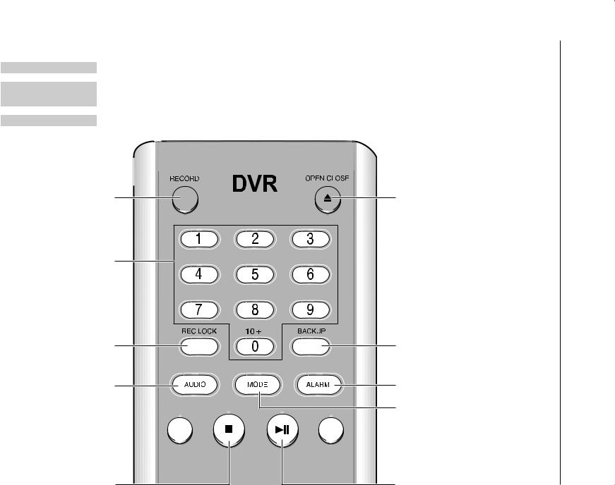
RECORD
Starts or ends the recording.
0~9
Selects a single channel while in live mode. Used for inputting numeric values.
REC LOCK
Locks the record function.
AUDIO
Toggles Audio On and
Off.
FR (fast rewind) 


FR (fast reverse): Used for quick backward search while in play. (-x2, -x4, -x8, -x16, -x32, -x64)
 OPEN/CLOSE
Used to open and close the DVD-RW tray (SHR-5162, SHR-5082 only).
 BACKUP
Press it for backup operation.
 ALARM
ALARM
Cancels sending alarms.
 MODE
MODE
Select a split screen.

 FF (fast forward)
Used for quick forward search while in play. (x2, x4, x8, x16, x32, x64)
CONTROL REMOTE
07_ introducing
STOP 

Ends playing.
ZOOM
Implements the digital zoom (x2).
MENU
Goes to the system menu screen or moves to the upper menu.
UPDOWNLEFT RIGHT
Used for changing settings or for moving the cursor up/down/left/right.
PTZ
Toggles PTZ mode On
and Off.
TELE
Performs the TELE function in PTZ mode.
WIDE
Performs the WIDE function in PTZ mode.
 Play/Pause

Pauses or resumes playing.
 FREEZE
Performs the FREEZE function in live mode.
 SEARCH
Goes to the search select screen.
 ENTER
ENTER
Shows the cursor for channel selection in live mode or used as the selection button for menu configuration.
 SYS ID
Use for inputting or confirming system or remote control ID.
 PRESET
Performs the PRESET function in PTZ mode.
 VIEW
VIEW
Performs the VIEW function in PTZ mode.
Changing the Remote Control ID
As you press the SYS ID button, input the desired 2-digit ID in order (Remote control default ID: 00).
For instance, to change the remote control ID to 08, press the SYS ID button, and then input 0 and 8 buttons in order. After the input completes, press the SYS ID button again in order to confirm the setting.
01INTRODUCING

installation
You should pay attention to the following before you use the product.
Do not use it outdoor.
Do not place water or liquid near the connection part or the product.
Do not impose excessive shock or force.
Do not pull out the power cord unreasonably.
Do not disassemble the product on your own.
Do not exceed the rated input or output voltage range.
Use the certified power cord only.
For the product with an input ground, use a power plug with a ground pin.
CHECKING INSTALLATION ENVIRONMENT
Samsung Digital Video Recorder (hereinafter referred to “DVR”) is a high-tech security equipment that contains a high-capacity HDD and top-notch circuits. High temperature inside or outside of the product may reduce the product life, deteriorate performance (see the graph below; it explains the correlation between temperature and product life), and lead to a malfunction.
Temperature |
One Year: 24HR X 365 DAY =8,760 HR |
Unit: ºC |
|
Life (Unit: HOURS)
Figure 1
Please keep the following instructions for rackmounting the Samsung DVRs to proceed with the installation.
1.The rack on which the DVR is mounted should not be sealed off.
2.And it also can allow air circulation through the vent.
3.As shown in the Figure 2, we recommend you to heap the product with other DVRs or use rack-mount devices at a certain space, or install a vent system to accommodate airflow.
4.For forming a natural convection, the air intake hole should be positioned at the bottom and the emission at the top.
5.We recommend you to install each of the air intake and emission holes with fan motors for sufficient airflow. (The air intake fan should be equipped with a filter to prevent possible inflow of dust and other impurities.
6.As shown in the Figure 1, the temperature inside the rack and around the DVR should maintain between 0°C ~ 40°C (32°F ~ 104°F).
HDD ADDITION
The user can add up to two hard disks to this product. However, there are many factors that can cause electric shock, accidents, and malfunctioning of the device inside of the product.
When the user does not correctly install or apply the proper settings, the device may not recognize the hard disks or the device will not properly run. Therefore, before adding any hard disks, it is recommended that you consult the specialist from the site where you purchased the product.
Figure 2
08_ installation
[Checking HDD Data]
CAUTION Please, pay attention to Following information to minimize the
chance of losing HDD data.
Remember that you should protect HDD from any impact or misuse as this may cause damaged.
The Manufacturer is not responsible for missing data or defects caused by the user’s mishandling.
Note: Adding Extra HDD. Check in advance that the HDD is compatible with the manufacturer’s DVR.
Examples that can cause loss of data or damage HDD.
Any outside Impact on the case which could happen whilst disassembling or setting up the DVR.
Power cut or incorrect shutdown whilst the DVR is operating.
Moving or causing any impact on the DVR during operation. Please, back up events as soon as possible to minimize disappointment should HDD data be lost.
Things to consider when adding a hard disk
When adding a hard disk, pay attention so that the cable doesn’t get caught between unsuitable places or the cable’s insulation is not damaged. (This may cause a malfunction or fire.)
When adding a hard disk, be careful not to have any injury by the pointed edges inside the product.
Pay attention not to lose screws or accessories.
If the screws or accessories are not put together, the product may malfunction or not properly operate.
If you contact the RTC battery while adding hard disks, the battery failure may happen. In this case, you will encounter failures when setting the time and operating DVR.
If you don’t connect fan power cables after adding hard disks, the fan failure message appears on the screen. This can cause operation failures because it raises the temperature inside your DVR.
Check the compatibility list of HDDs before installing additional HDDs. The list of the compatible devices with Samsung DVR can be obtained from your vendor.
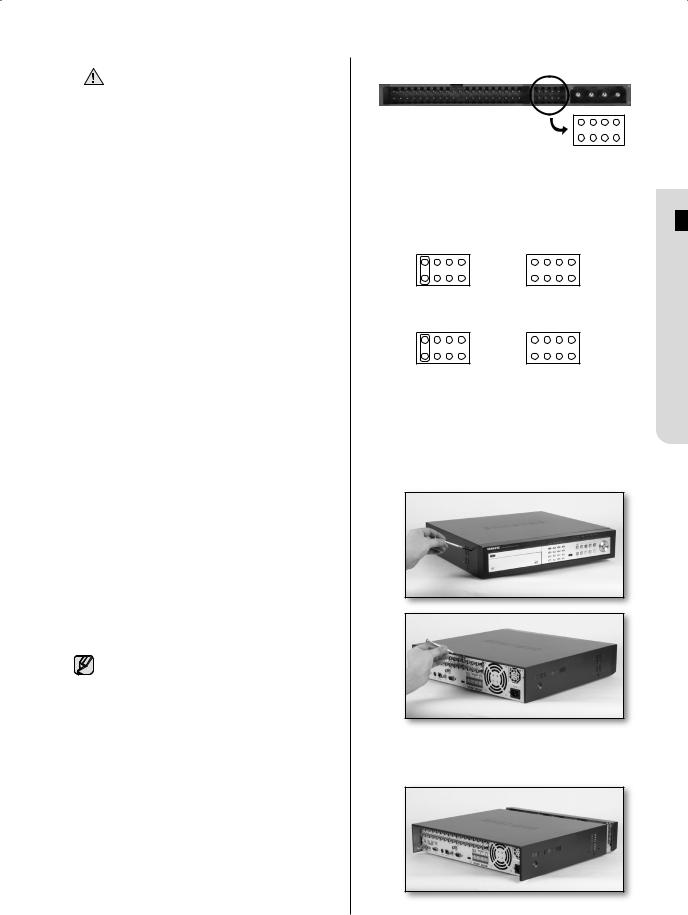
Setting the jumper
The jumper setting method is illustrated on the surface of the purchased HDD.
Using SAMSUNG hard disk, the jumper setting method is as follows:
HDD jumper for Primary Master and Primary Slave.
Jumper setting for Secondary Master (DVD-RW) and Secondary Slave.
How to add hard disks SHR-5082, SHR-5162
Before starting this work, remove the power cord from the outlet.
1.Take out the screws on the left and right sides (5 spots for each side) and on the rear (1 spot).
2.Remove the cover from the product. (Slide the cover slightly backward, lift it upward and remove it.)
 INSTALLATION 02
installation _09

3.There are brackets (Bracket-HDD) mounted on the right and left sides where you can mount HDDs. Remove the screws holding each bracket to mount an HDD onto.
BRACKET-
HDD(B)
BRACKET-
HDD(A)
4.If you want to add a hard disk, remove Bracket-HDD(A), power supply cable, signal transmission cable (IDE Cable), and fan cable.
BRACKET-HDD(A)
SCREW-SPECIAL
Screwdriver
10_ installation
5.To add a hard disk, the built-in HDD (Primary Master) should have been installed. Basically a built-in HDD has been installed as the Primary Master and a DVD-RW driver as the Secondary Master. Before adding a hard disk, set the jumper for master and slave. The jumper setting method is illustrated
on the surface of the purchased hard disk. Fix the hard disk to the Bracket using the (A)SCREW-SPECIAL (BWH, 6-32UNC, L10. 5). Align the 5 spots on the bottom and mounting holes of the Bracket, insert the HDD, and then fix it using the screws.
Screwdriver
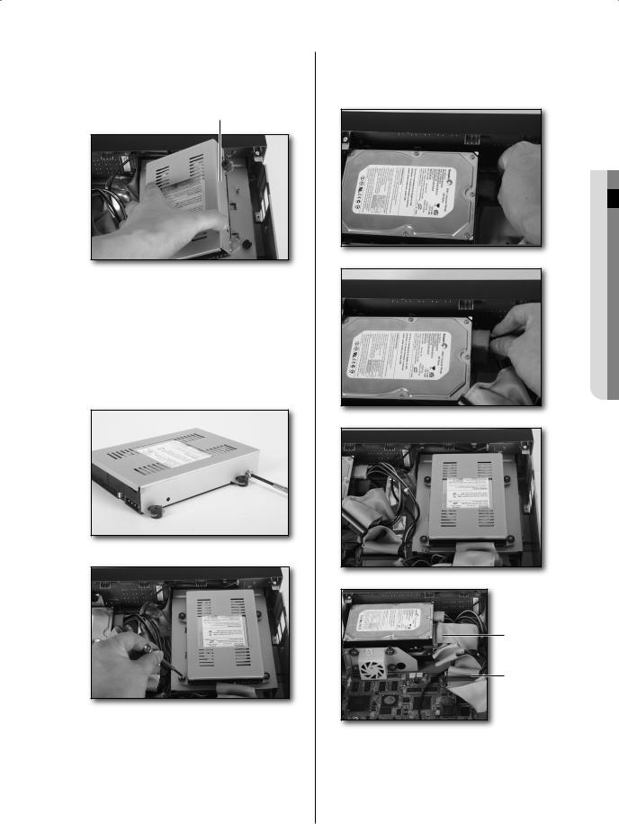
6.To add another hard disk after adding a hard disk completes, remove the Bracket-HDD(B) on the DVD-RW driver.
BRACKET-HDD(B)
7.Fix the hard disk to the Bracket using 4 (B)SCREW-MACHINE (6-32UNC, L4. 2) provided when purchasing the HDD. The screws should be fastened not to come loose. Fix the Bracket-HDD(B) using screws after aligning 4 spots on the bottom and mounting holes.
8.When adding hard disks completes, connect the power supply cable, signal transmission cable (IDE Cable), and fan cable to the hard disks.
INSTALLATION 02
Primary HDD
IDE Connector
Secondary HDD
IDE Connector
9.After checking whether or not the connections have no problem, close the cover.
10. Fix the cover using screws. (Each of left and right sides has 5 spots and the back side has 1 spot.)
installation _11
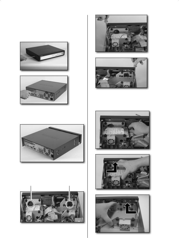
SHR-5080, SHR-5160
Before starting this work, remove the power cord from the outlet.
1.Take out the screws on the left and right sides (5 spots for each side) and on the rear (1 spot).
2.Remove the cover from the product. (Slide the cover slightly backward, lift it upward and remove it.)
3.There are brackets (Bracket-HDD) mounted on the right and left sides where you can
mount HDDs. Remove the screws holding each bracket to mount an HDD onto.
 Bracket-HDD
4.If you want to add a hard disk, remove BracketHDD, power supply cable, signal transmission cable (IDE Cable), and fan cable.
12_ installation

5.To add a hard disk, the built-in HDD (Primary Master) should have been installed. Basically a built-in HDD has been installed as the Primary Master. Before adding a hard disk, set the jumper for master and slave. The jumper setting method is illustrated on the surface of the purchased hard disk. Fix the hard disk to the Bracket using the (A)SCREW-SPECIAL (BWH, 6-32UNC, L10. 5).
6.Re-mount the bracket-HDD mounted with the HDD’s to the place where it was separated from. Place the bracket-HDD so that all five mounting spots on the bottom and the bracket-HDD’s mounting holes are perfectly aligned, then slide it toward the outside of the product and tighten the screws.
7.When adding hard disks completes, connect the power supply cable, signal transmission cable (IDE Cable), and fan cable to the hard disks.
8.After checking whether or not the connections have no problem, close the cover.
9.Fix the cover using screws. (Each of left and right sides has 5 spots and the back side has 1 spot.)
 INSTALLATION 02
installation _13

connecting with other devices
The illustrations are described based on SHR-5162.
CONNECTING VIDEO, AUDIO, AND MONITOR
CONNECTING THE NETWORK
Connecting to Internet through Ethernet (10/100BaseT)
14_ connecting

Connecting to Internet through ADSL
 CONNECTING 03
CONNECTING THE USB
1.There are two USB connecting ports on the front and rear panels of the product.
2.USB Hard Disk, USB CD/DVD, and USB Memory can be connected through any of those ports.
3.If the USB HDD is connected to the system, it should be detected and set through
Menu > System > Storage Setup before operation.
4.The product provides the HOT PLUG feature that allows the connection/removal of USB devices during system operation.
|
The USB type of hard disk |
CAUTION |
should be set to Master. |
|
If the backup USB device cannot |
|
be formatted in the DVR, format |
|
it as FAT32 using your PC. |
For more details, refer to the System section in Chapter 5 Menu Setup.
CONNECTING THE ALARM INPUT/OUTPUT
The Alarm IN/OUT ports on the rear of the product have the following elements:
5080/5082 Alarm IN/OUT Ports
5160/5162 Alarm IN/OUT Ports
ALARM IN 1 to 8 (SHR-5080/5082): Alarm input port
ALARM IN 1 to 16 (SHR-5160/5162): Alarm input Port
ALARM RESET: When receiving an ALARM RESET signal, the system clears the current ALARM input or output signal and resumes alarm sensing.
ALARM OUT 1 to 4: Alarm output ports
connecting _15

CONNECTING THE RS-485 DEVICE
You can connect an RS-485 device through a rear port of the product. For example, you can connect and control PTZ cameras supporting the RS-485 communication.
You can also adopt either Half Duplex or Full Duplex method for exchanging data.
PTZ device |
|
|
|
|
|
Rear |
|
|
|
|
|
|
|
|
|
Half Duplex Type |
|
|
|
|
|
|
|
Data (–) |
|
|
|
|
|
|
|
|
|
|
|
|
Tx(–) |
||
Data (+) |
|
|
|
|
|
||
|
|
|
|
|
|||
|
|
|
|
|
Tx(+) |
||
|
|
|
|
|
|
|
|
|
|
||||||
|
|
|
|
|
|
|
|
|
|
|
|
|
|
|
|
Full Duplex Type |
|
|
|
|
|
|
|
Rx(+) |
|
|
|
|
|
|
|
|
|
|
|
|
|
||
Rx(–) |
|
|
|
|
|
|
Rx(–) |
|
|
|
|
|
|
||
Tx(–) |
|
|
|
|
|
Rx(+) |
|
|
|
|
|
|
|||
Tx(+) |
|
|
|
|
|
||
|
|
|
|
|
|
||
|
|
|
|
|
|
|
|
|
|
|
|
|
|
|
|
Supportable baud rates are 600, 1200, 2400, 4800, 9600, 19200, and 38400.
Check if the RS-485 device is CAUTION compatible with the product first.
Then pay attention not to change the polarity (+/-) of RS-485 when connecting it.
16_ connecting
live
OPERATING THE SYSTEM
Turn on the power and the following Samsung logo appears.
Upon completion of initializing procedure, the live screen appears with a beep sound. (It takes about one minute until a live screen comes up.)
If a new HDD is installed, the initialization may take much more time because it includes a new HDD initialization.
If the live screen does not appear or the LEDs on the front panel repeat flickering, please check the connections. If the system does not operate normally, contact the expert from the shop where you bought the product.
The live screen does not affect the earlier MENU settings. If you reboot the system when a recording is in progress, the recording will start again.
LIVE SCREEN MODE
Live screen icons
The live screen icons display the status of current setup or function.
CAM 01
CAM 01


 : Recording icon
Each icon represents Normal/Event (Alarm+Motion)/Schedule Recording.


 : Recording Video Size icon
Each icon represents the recording size of Normal or CIF.
Normal: Half D1—(NTSC) 720x240, (PAL) 720x288
CIF: CIF— (NTSC) 352x240, (PAL) 352x288
Half D1 is an MPEG-4 video encoding mode in which half the horizontal resolution is sampled.
 : Record Lock icon
It indicates that the record lock is activated. This icon appears when you are recording video images while the record lock is set. To cancel the recording, enter the preset password.
LIVE 04
live _17


 : PTZ icon
This icon appears when setting the PTZ device and it changes to yellow when operating the PTZ.


 : Audio icon
This icon represents the ON/OFF status of audio and it changes to yellow when the audio is set to ON. It does not appear in Video mode or when the audio is disabled.
 : Sensor Active icon
This icon appears in the channel linked with the external sensor signal when the sensor is active.
 : Motion Event icon
This icon appears in the Motion Event channel when the motion detection is set to ON.
 : Zoom icon
This icon appears while the Zoom operation is active and disappears by canceling the operation.


 : Freeze icon
This icon appears in Freeze mode and disappears by canceling the freeze operation.
 : Recording Hard Disk Full icon
This icon appears when the hard disk space is not sufficient when recording.
 : Auto Sequence icon
This icon appears in Auto Sequence mode.
 : Backup Play icon
This icon appears when the backup data is now played.
 : Fan Error icon
This icon appears when the fan does not work properly.
 : No HDD icon
This icon appears when there is a dysfunctional hard disk.
When the Fan Error icon or No HDD icon appears, please contact the service center.
V.Loss/V.Off: Video input status
When there is no video data input while the video is active, V.Loss appears in the channel. When you set the Video On/Off to OFF, V.Off appears.
Live screen modes
The SHR-5162/5160 models receive 16 live images and displays them in the following 9 modes as shown in the picture. To see each mode in order, repeatedly press the MODE button on the front panel or remote control. But the SHR-5082/5080 models have no 16-split mode.
CAM_01 |
CAM_02 |
CAM_03 CAM_04 |
|
CAM_01 |
CAM_02 |
CAM_03 |
|
|
|
|
|
CAM_02 |
|
|
|
|||||
|
|
|
|
|
|
|
|
|
|
|
|
|
|
|
||||||
CAM_05 |
CAM_06 |
CAM_07 |
CAM_08 |
|
|
|
|
|
|
|
CAM_01 |
CAM_02 |
|
|
|
CAM_01 |
CAM_02 |
|||
|
|
|
|
|
|
|
CAM_04 |
CAM_05 |
CAM_06 |
|
|
|
|
CAM_01 |
CAM_03 |
|
|
|
||
CAM_09 CAM_10 CAM_11 |
CAM_12 |
|
|
|
|
|
|
|
|
|
|
|
|
|
|
CAM_04 CAM_05 |
||||
CAM_13 CAM_14 CAM_15 |
CAM_16 |
|
CAM_07 |
CAM_08 |
CAM_09 |
|
CAM_03 |
CAM_04 |
|
CAM_04 CAM_05 CAM_06 |
CAM_03 |
CAM_06 CAM_07 |
||||||||
16 Split Mode |
|
|
9 Split Mode |
|
4 Split Mode |
|
6 Split Mode |
|
7 Split Mode |
|||||||||||
|
|
|
|
|
||||||||||||||||
|
|
|
CAM_02 |
|
|
|
|
|
|
|
|
|
|
|
|
|
|
|
||
|
|
|
CAM_03 |
|
|
|
|
|
|
|
|
|
|
|
|
|
|
|
||
CAM_01 |
|
|
CAM_04 |
|
|
|
|
|
|
|
|
|
|
|
|
|
|
|
||
|
|
|
|
|
|
|
CAM_01 |
|
CAM_02 |
|
CAM_01 |
|
|
|
CAM_01 |
|
|
|
||
CAM_05 CAM_06 |
CAM_07 CAM_08 |
|
|
|
|
|
|
|
|
|
|
|
|
|||||||
|
|
|
|
|
|
|
|
|
|
|
|
|
|
|
||||||
8 Split Mode |
|
|
|
PIP Mode |
|
|
Auto Sequence Mode |
Single Mode |
|
|||||||||||
|
|
|
|
|||||||||||||||||
18_ live
Full Screen (Single) mode:
Displays the selected channel in full screen.
4, 6, 7, 8, and 9 Split mode:
Displays 4, 6, 7, 8, 9 channels in each split screen. You can select channel numbers on your own using the MODE button on the front panel or remote control. In 4-channel and 9-channel split modes, the screen page is changed using the Direction buttons.
16 Split mode:
Displays 16 live channels on a 16-split screen. The Auto Sequence is not available.
PIP (Picture in picture) mode:
Displays a small screen on a full screen. You can change the channel number on a full screen or small screen by pressing the ENTER button and inputting the NUMERIC button. To switch between main and sub screens, press the ENTER button and press the LEFT or RIGHT direction button. You can move
the sub screen to 5 different stages using the UP/DOWN direction buttons.
Auto Sequence mode:
Sequentially displays all the channels at an interval of auto sequence time. The auto sequence time is set in Camera Configuration on the menu.
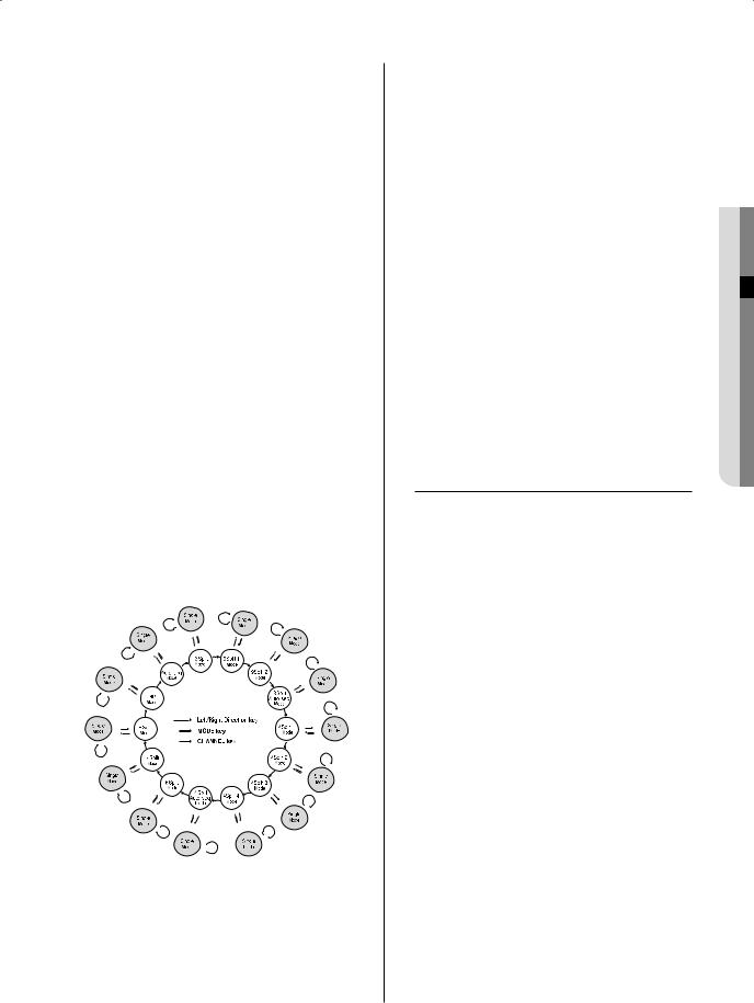
Selecting live screen mode
Available modes are switched using the MODE button and the NUMERIC buttons on the front panel or remote control. The following figure is the live modes transition diagram in the SHR-5162/5160 models.
The initial live screen shows the 16-split screen mode at first. The SHR-5082/5080 models start from the 9-split mode.
In the 9-split screen mode, the first screen shows 9 channels (CH 1 to CH 9) and the second screen shows the rest 7 channels (CH 10 to CH 16) after pressing the RIGHT direction button. If you press the RIGHT direction button again, it changes to the Auto Sequence mode.
Likewise, in the 4-split screen mode, the first screen shows 4 channels (CH 1 to CH 4), the second screen shows CH 5 to CH 8, the third screen shows CH 9 to CH 12, the fourth screen shows CH 13 to CH 16. If you press
the RIGHT direction button again, it changes to the Auto Sequence mode.
Every time you press the MODE button, the modes change in the following sequence: 16-split mode 9-split mode 4-split mode 6-split mode 7-split mode 8-split mode PIP mode Auto Sequence mode 16-split mode.
Press the CH 1 to CH 16 button to see a full screen of each channel after pressing the ENTER button.
Press the MODE button after entering a full screen channel in a split screen mode to return to the previous split mode screen.
SETTING AUDIO ON/OFF
In other split modes except full screen mode, 16-split mode, and auto sequence mode, you can choose a channel to be displayed by
pressing the ENTER and NUMERIC buttons. If you set the selected channel to Audio On, you can turn the Audio On and Off in live mode.
Audio On/Off setting in full screen mode
In full screen mode, the audio of the selected channel automatically turns on. You can turn the audio On and Off by toggling the AUDIO button. Depending on the audio On/Off setting condition, the Audio icon of the channel changes to yellow and white.
Audio On/Off setting in 16-split mode
When pressing the ENTER button in the 16-split mode, the selection cursor appears for you to select a channel. When you select a channel and press the AUDIO button on the front panel or remote control, the audio of the selected channel is changed to On or Off.
Depending on the audio On/Off setting condition, the Audio icon of the selected channel changes to yellow and white. You can have audio settings on channel 1 to 4 in 16-split mode.
LIVE 04
live _19

Audio On/Off setting in 4, 6, 7, 8, and 9-split modes and PIP mode
As in 16-split mode, when pressing the ENTER button in 4, 6, 7, 8, and 9-split modes and PIP mode, the selection cursor appears for you to select a channel.
After selecting a channel, you can set the Audio to On or Off using the AUDIO button. According to the audio On/Off setting condition, the Audio icon of the selected channel changes to yellow and white.
FREEZING AND ZOOMING
Freeze function
The freeze function pauses the video image on the live screen and it is only available in the live mode.
You can set this function to On or Off using the FREEZE button on the front panel or remote control.
Zoom function
The zoom function enlarges the selected area to double size, and it is only available in the single screen mode.
When you press the ZOOM button on the front panel or remote control, the zooming area appears. Use the UP/DOWN/LEFT/RIGHT direction buttons to adjust the position for zooming. After selecting the Zoom area, press the ENTER button to enlarge the selected area in double size. To cancel the zooming function, press the ZOOM button again.
EVENT MONITORING
The event monitoring is used to display the channel that is synchronized with an event on the screen when a special event (Sensor/Motion/ Video Loss) occurs. The settings for event monitoring activation and event duration setup are done in the Monitoring on the menu.
If you set the event monitoring interval to 5 seconds and an event occurs at CH 2 as shown in the picture, the system will display CH 2 in full screen for 5 seconds. If another event occurs within 5 seconds, it is also displayed together with the existing event.
As shown in the picture, if we assume that both CH 1 and CH 3 events occur within 5 seconds (for example, after 4 seconds), after CH 2 event, these three events are displayed with split into 4 screens.
If a new event does not occur during the event duration, the system will return to the previous live mode. Pressing the ALARM button during the event duration makes the event monitoring stop. When an event occurs, the ALARM LED is turned on. Press the ALARM button again to turn ALARM LED Off. At this time, the alarm
setup is initialized, the event icon disappears, and the event monitoring is cancelled while in event monitoring. After alarming, the event recording resumes.
[ Event-driven screen changes in Event Monitoring ]
20_ live

SPOT-OUT MONITORING
Spot-out monitoring has nothing to do with the live screen output. It monitors a
specific channel in full screen. After selecting Monitoring on the MENU, you can select a channel for monitoring in Spot Out Channel. You can also monitor all the channels at an interval of auto sequence time.
In case of spot-out monitoring, the live screen icons do not appear.
If the Spot Out Event Monitor is set to On, you can see the event channels.
When the events occur sequentially, the channel of the camera that the last event has been issued is displayed. (In case of alarms, multiple channels are enabled.)
When multiple cameras are connected, the camera with the smallest number is output on Spot-out channel.
In the live screen, you can select a spotout channel as described below:
Press the STOP button on the front panel or remote control and press a button out of 16 channels. The selected channel is set to a spot-out channel.
When you press the STOP button and then the MODE button within 2 seconds, the spot-out channel mode is changed to the change screen mode.
|
If the built-in HDD is not connected |
||
CAUTION |
|
or it is out of order, the system |
|
|
|
displays an error ( |
) saying “built- |
|
|
in HDD error” at the top-left corner. |
|
|
|
In this case, you cannot perform |
|
|
|
recording, playback, and backup. |
|
|
|
So please contact the service |
|
|
|
personnel. |
|
|
If the fans in the product do not |
||
|
|
properly operate or have some |
|
|
|
problem, the fan error message |
|
|
|
appears on the live screen as shown |
|
|
|
in the following picture. In this case, |
|
|
|
check whether the fans normally run |
|
|
|
or not. When the fans are recovered, |
|
|
|
the Failure icon ( |
) that is displayed |
|
|
at the top-left corner disappears. In |
|
|
|
case of a fan failure, it can shorten |
|
|
|
the life of the product so please |
|
|
|
contact the service personnel. |
|
|
|
|
|
|
|
Fan Information |
|
|
|
|
|
|
|
A error occurs in the fan. |
|
|
|
Refer to the manual. |
|
|
|
|
|
LIVE 04
live _21
menu setup
BEFORE USE
The menu structure is as follows:
MENU SETUP
System |
Date/Time/Language |
|
|
Camera |
Password |
|
|
Load Factory Default |
|
||
Monitoring |
|
||
System Log |
|
||
|
|
||
Record Mode |
Event Log |
|
|
Event Record |
System Information and Setup |
||
Storage Setup |
|
||
Schedule |
|
||
Export/Import the Configuration |
|||
|
|||
Backup |
Remote Control Device |
||
Network |
|
|
|
Move/Control |
Select |
MENU Exit |
|
Selection
The yellow cursor is the selection bar. Use the Direction buttons on the front panel or remote control to move the cursor to a desired menu. If you press the ENTER button when the cursor is located in a desired menu, the screen displays the sub window.
To select an item from the menu, press the ENTER button. On a drop-down menu, use the UP/DOWN direction buttons to move the cursor on your desired item.
OK and Cancel in each Setup window Once any changes are made in a setup window, they can be applied by selecting OK.
When Cancel is selected, the changed settings are not applied and it returns to the upper menu.
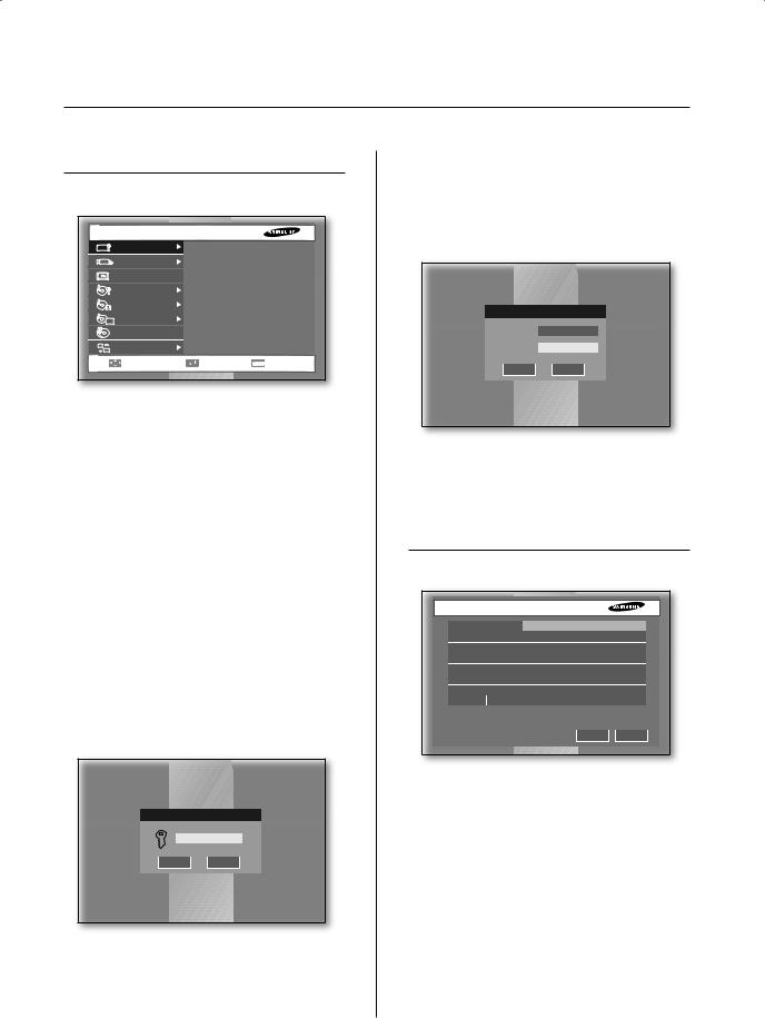
MENU button
When the MENU button is pressed in any of the Setup menus, it changes to the upper menu. If you press the MENU button in Live
mode, the password window appears for user validation.
Admin Password
OK Cancel
SEARCH, BACKUP, PTZ, POWER buttons in Live mode
To perform the search, backup, PTZ controls, or shutdown function, press the following button in Live mode. Then the window asking for an ID and password appears for user validation.
Enter ID and Password
ID Admin
Password
OK Cancel
The direction sign (► or ▼) right next to the title of menu or item leads you to press the displayed button on the front panel or remote control to go for sub item.
SYSTEM
Date/Time/Language Setup
 Date/Time/Language Setup
Date |
|
2007-08-01 |
|
Time |
|
10:00:00 |
|
Time Zone |
|
(GMT+01:00) |
|
Time Synchronization |
Setup |
|
|
Date Format |
|
YYYY-MM-DD |
|
Time Format |
|
24 Hours |
|
Language |
|
English |
|
DST |
Off |
Mar-last-Sun 01H ~ Oct-last-Sun 01H |
|
|
|
OK |
Cancel |
Date
Press the ENTER button and use the LEFT or RIGHT direction button to move to year, month, and day. To change the value, use the UP or DOWN button. Press the ENTER button to confirm the setting.
Time
Press the ENTER button and use the LEFT or RIGHT direction button to move to hour, minute, and second. To change the value, use the UP or DOWN button. Press the ENTER button to confirm the setting.
22_ menu setup

[Date/Time Change]
CAUTION After the date and time has been changed, the data recorded before
the change can be removed. For example, if the current time is changed from 8 to 7, all the data recorded between 7 and 8 will be deleted.
Time Zone
Set the local time zone based on the Greenwich Mean Time (GMT).
Time Synchronization
The time of your DVR can be synchronized by a specified server. For this purpose, enter the IP address of the time server and determine the initiator of this activity.
-Automatic Time Synchronization
Synchronizes while gathering time information from the Time Server (IP)
-Activate by Server(Master)
Time Synchronization is executed while more than two DVR devices are connected, and the operating DVR device connected to the server is set as standard.
 Time Synchronization Setup
Automatic Time Synchronization |
Off |
|
|
Time Server(IP) |
|
203.248.240.103 |
|
Activate by Server(Master) |
|
Off |
|
Last Synchronization Time |
2007-01-26 12:39:12 |
Fail |
|
OK Cancel
Date Format
The system supports 3 types of formats: YYYY-MM-DD, DD-MM-YYYY, and MM-DD- YYYY.
Time Format
The system supports 2 type of formats: 24 Hours and 12 Hours(AM/PM).
Language
After selecting a language, on-screen display (OSD) menus are displayed in the selected language.
DST (Daylight Saving Time)
DST sets the clock one hour ahead the local standard time. This setting enables the system to display the time adjusted for DST. If the DST is set to Off, it does not apply. To set the DST, enter the start time and end time on the right. It allows you to set month, week (e.g. 1st, 2nd, 3rd, 4th, last), date, and time only.
Password
The factory default password for Admin and user privileges is “4321.” The Menu Setup window cannot be accessed by user privileges but by the Admin privilege. The Admin user can give users (User1 to User5) access rights to the selected functions. If you press Setup in User Authority, all the access rights are selected.
 Password
Admin Password |
|
|
|
New Password |
|
Confirm |
|
Password Lock |
|
On |
|
Record Lock |
|
Off |
|
User Password |
|
|
|
User Setup |
|
User1 |
|
New Password |
|
Confirm |
|
User Authority |
|
Setup |
|
Search |
Backup |
PTZ |
Shutdown |
All Key Lock On |
|
OK |
Cancel |
New Password
You can change the password by entering a new password value in this field. The input password is allowed up to 8 digits. Press the ENTER button and enter numbers using the NUMERIC buttons on the front panel or
remote control. Press the ENTER button again for confirmation. Then the cursor moves to the
New Password Confirm field.
Confirm
It confirms that the newly input password is correct. Enter the new password again in the field.
Password Lock
If it is set to On, a pop-up window for asking the password appears every time you select a menu. If it is set to Off, you can enter menus without entering the password.
Record Lock
If the Record Lock is set to On, a pop-up window, asking for the password appears while disabling the recording.
User Authority
You can select any of Search, Backup, PTZ, and Shutdown. If the user has no access right for Search, the user cannot enter the Search menu.
All Key Lock On
If you select this, the system will enter the live mode immediately. If you press any button on the front panel or remote control, the password input window appears. If the correct password is input, the lock function is deactivated.
[All Key Lock On]
If you select this, the system immediately switches to the live mode and all buttons are locked.
If the user enters the selected function, he or she has to input the password first.
menu setup _23
 SETUP MENU 05
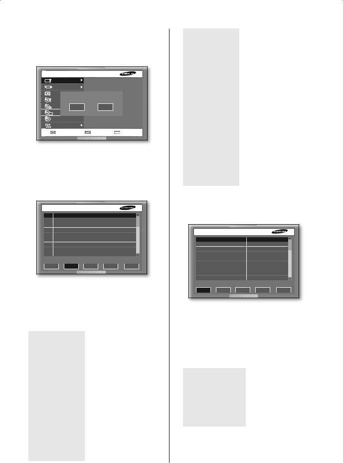
Load Factory Default
It is used to initialize all the settings to the factory default values. The recorded video data will not be removed. Select OK to start initialization.
MENU SETUP
System |
|
Date/Time/Language |
|
Camera |
|
Password |
|
|
Load Factory Default |
|
|
Monitoring |
|
|
|
|
|
|
|
Record |
Sure to default setting? |
|
|
|
|
|
|
Event |
OK |
Cancel |
|
|
|
||
Schedule |
|
|
|
Backup |
|
Remote Control Device |
|
Network |
|
|
|
Move/Control |
Select |
MENU Exit |
|
System Log
The System Log is used to check the important history records by an administrator. The log data includes the system-related logs such as system start, system termination, menu setup change, and the like.
 System Log
No. |
System Log List |
|
Date/Time |
|
46 |
Setup Start (Local) |
|
2007-08-01 10:00:29 |
|
45 |
Setup End (Local) |
|
2007-08-01 10:00:29 |
|
44 |
Setup Start (Local) |
|
2007-08-01 10:00:29 |
|
43 |
Setup End (Local) |
|
2007-08-01 10:00:29 |
|
42 |
Setup Start (Local) |
|
2007-08-01 10:00:29 |
|
41 |
Setup End (Local) |
|
2007-08-01 10:00:09 |
|
40 |
Setup Start (Local) |
|
2007-08-01 09:59:38 |
|
39 |
Setup End (Local) |
|
2007-08-01 09:59:30 |
|
First |
Prev |
Next |
Last |
Exit |
Available action buttons are:
First: Moves to the first log page.
Prev: Moves to the previous log page.
Next: Moves to the next log page.
Last: Moves to the recent log page.
The system logs are as follows:
System Start |
Starts the system. |
|
|
Login(Admin) |
Viewer Login (Admin) |
|
|
Logout(Admin) |
Viewer Logout (Admin) |
|
|
Login(User) |
Viewer Login (User) |
|
|
Logout(User) |
Viewer Logout (User) |
|
|
Setup Start (Local) |
Enters into the menu. |
|
|
Setup End (Local) |
Comes out of menu. |
|
|
Setup (Remote): |
Sets the menu. |
Viewer |
|
|
|
Play Back Start |
Starts the playback. |
|
|
Play Back End |
Ends the playback. |
|
|
Power Failure |
Returns the system after |
Recovery |
power interruption. |
|
|
Time Change |
Changes the Date/Time. |
|
|
Load Factory Default |
Initializes the system. |
|
|
System Upgrade |
Changes the system S/W. |
|
|
Disk Full |
No Space in the HDD |
|
|
Backup Start |
Starts the backup. |
|
|
Backup End |
Ends the backup. |
|
|
Backup Stop |
Stops the backup. |
|
|
Backup Fail |
Backup Failure |
|
|
ATA HDD Erase |
Erases the ATA Data. |
|
|
USB HDD Erase |
Erases the USB HDD data. |
|
|
USB MEMORY |
Erases the USB MEMORY data. |
Erase |
|
|
|
Overwrite Playback |
Stops the playback by |
Stop |
overwrite. |
|
|
Backup |
Stops the backup by |
Stop(Overwrite) |
overwrite. |
|
|
Event Log
It is used to check the recorded events like alarm, motion, video loss, and such.
 Event Log
No. |
Event Log List |
Date/Time |
4 |
Video Loss CH[2] |
2007-08-01 10:00:29 |
3 |
Video Loss CH[1] |
2007-08-01 10:00:29 |
2 |
Video Loss CH[2] |
2007-08-01 10:00:29 |
1 |
Video Loss CH[1] |
2007-08-01 10:00:29 |
First |
Prev |
Next |
Last |
Exit |
The log data contains the event execution data and time.
First: Moves to the first log page.
Prev: Moves to the previous log page.
Next: Moves to the next log page.
Last: Moves to the recent log page.
The event logs are as follows:
Video Loss CH[N] |
Means the occurrence |
|
of Channel [N] Video |
|
Loss. |
|
|
Alarm Detection CH[N] |
Means the occurrence |
|
of Channel [N] alarm. |
|
|
Motion Detection CH[N] |
Means the occurrence |
|
of Channel [N] Motion. |
|
|
24_ menu setup
System Information and Setup
System Information and Setup
System Information |
|
Software Version |
B3.09-K1.53-V2.20_0707051455 |
Broadcast Format |
NTSC |
Mac Address |
00:16:6C:22:28:EF |
USB S/W Upgrade |
|
|
Version |
B3.09-K1.53-V2.20_0707071230 |
|
|
OK |
Cancel |
This setup window provides the following setting items:
Software Version: Displays the current software version. The value cannot be changed.
Broadcast Format: Displays the current broadcast format (NTSC/PAL). The value cannot be changed.
Mac Address: 6-Byte hardware address. The value cannot be changed.
USB S/W Upgrade
You can update the software using a USB device. If there is no device, None is displayed. If the USB memory has an upgrade software, its version is displayed.
To upgrade the software stored in the USB device, select the check box on the right and press OK.
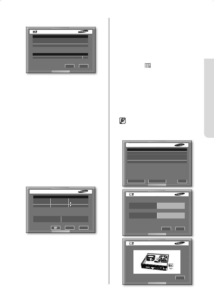
Storage Setup
You can configure the storage device related settings.
 Storage Setup
Device Information |
|
|
|
Device |
No |
Used/Total |
Erase Usage |
ATA |
1 |
0.00/235.66G |
Internal |
USB Memory |
1 |
0.00/494.98M |
Backup |
Disk End Mode |
OverWrite |
|
Disk End Beep |
Off |
|
|
OK |
Cancel |
Device Information
Displays the number, capacity, and usage of ATA and USB devices. (The total capacity displayed may be lower than the actual
capacity because the DVR uses some portion of it for internal purpose.) After selecting Erase for each device, you can remove the data
on it. In case of USB device, you can set the usage for extension or backup. If you change the usage of the device, the stored data will be removed.
Disk End Mode
-Stop: Stops recording when the disk is full while recording is still in progress.
-Overwrite: Deletes the previously recorded data to store new data when the disk is full during recording.
Disk End Beep
-On: Beeps when the disk is full while recording.
-Off: Although the disk is full while recording, it doesn’t make beep sound.
HDD Installation Information
When you click ( ), The HDD Installation Information displays on the screen. Then you can
see the model name, the capacity, and the status of the HDD in your DVR. The status displays Good, Not good, and Check. In the status of Not good, you should replace the HDD. In the status of Check, you should replace the HDD or check periodically. After clicking the Alarm Setup, you can set the alarm and the duration while the status is Not good or Check. If you click the HDD location map, it displays the information about the HDD installation. When a problem occurs, you can see which HDD has a problem.
The capacity of the HDD may differently appear in the Storage Setup menu and HDD Installation Information menu.
In case of SHR-5160/5080, the model name of HDD appears instead of DVD RW.
 HDD Installation Information
No. |
Model |
Capacity |
Status |
1 |
ST3250823ACE |
250.05G |
Good |
2 |
ST3160212ACE |
160.04G |
Good |
3 |
DVD RW |
- |
- |
4 |
ST3250823ACE |
250.05G |
Good |
Alarm Setup HDD Location Map Exit
Alarm Setup
NG |
None |
|
Duration |
10 sec |
|
Check |
None |
|
Duration |
10 sec |
|
|
OK |
Cancel |
HDD Location Map
Exit
menu setup _25
 SETUP MENU 05
When the Disk end mode is set to
CAUTION Overwrite and the HDD overwrites the data that was previously backed
up, the backup start time may be changed or the backup process may be cancelled.
[Disk Overwrite]
When Overwrite is selected, the previous event data is to be deleted and the mode is also changed.
[Built-in HDD]
This is a physical hard disk connected to the IDE cable inside the main body, and it stores data.
[External HDD]
This is a physical hard disk connected to the port and jack on the rear of the main body, and it also stores data. This can be used as an extended hard disk or backup hard disk.
Extended HDD: Supplements the builtin HDD. It is located on the top of the built-in HDD.
Backup HDD: Used for backup of the data recorded on the HDD.
[ATA]: Built-in HDD
This is a disk drive implementation that integrates the controller on the HDD itself. It is a physical hard disk connected to the IDE cable inside the main body.
[USB]: External HDD
(Extension HDD or backup HDD) This is used for external HDD connection. The external HDD is connected through this USB port on the front or rear panel.
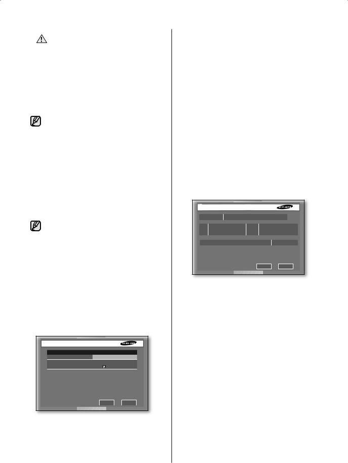
Export/Import the Configuration
This menu is used to export or import the DVRrelated settings to/from the USB memory.
 Export/Import the Configuration
Export the Configurations to USB Memory
Mode |
Export |
File Name |
07011000 |
Include N/W Settings |
|
Apply Cancel
The related settings are as the following:
Mode: You can select any of Import and Export.
File Name: In case of Export, the file name is displayed. The file naming convention is YYMMDD00. “00” is the serial number so it increases by 1. To change the file name, press the ENTER button. You can change the name using the virtual keyboard.
File Open: In case of Import, you can select the file that you want to import from the USB memory after pressing the ENTER button.
When the importing completes, your DVR automatically reboots.
Include N/W Settings: In case of Export, this flag is selected by default. But with Import, you can decide whether or not to copy the network settings. Be careful when you select this because it will remove the previous network settings.
Remote Control Device
 Remote Control Device
Device |
|
None |
|
|
|
ID |
Baudrate |
Parity |
Date |
Stop |
Duplex |
000 |
9600 |
None |
8 |
1 |
Half Duplex |
Remocon |
|
|
On |
|
ID:00 |
|
|
|
|
OK |
Cancel |
This menu enables you to use the Samsung system keyboard or remote control.
Device
It indicates a remote control device that is connected to the RS485 port.
ID
This is a unique ID of the device. This ID is necessary to control multiple DVRs.
Baudrate
Baud rate for communicating with cameras. It should be the same as the baud rate of cameras for communication.
Parity
Select one of None, Even, and Odd.
Data
Select one of 7 and 8.
Stop
Select 1 or 2 for stop bit.
Duplex
Select one of Half Duplex and Full Duplex. (Data exchanging method)
Remocon
Set the remote control to On or Off. You can set the ID of remote control to any of 0 to 99.
26_ menu setup
Loading...