


manual user SYSTEM RECORDING DIGITAL
SPR-9816/9716
DIGITAL RECORDING SYSTEM
user manual
imagine the possibilities
Thank you for purchasing this Samsung product. To receive a more comprehensive service,
please register your product at
www.samsung.com/global/register
AB82-01978A Rev-00
key features of your DVR
The SHR-9816/9716 compresses up to 16 video input signals using an advanced MPEG4 codec and up to 16 audio input signals using ADPCM for real-time simultaneous storage and playback from the hard drive. This unit is also capable of streaming these signals across various networks for remote monitoring.
16-Channel BNC Video Input Connectors
NTSC/PAL Video Source Compatible
Recording speed: 480 ips (NTSC) / 400 ips (PAL) using CIF resolutions (352x240 NTSC / 352x288 PAL)
Supports hard drive overwrite mode.
Supports USB 2.0 backup devices.
Supports remote monitoring via Windows Network with SPR Smart Viewer.
Record and playback 16 audio channels.
Includes various recording options/triggers (continuous, motion, object watch, sensor, POS, video loss, and 1 ch. instant recording)
Alarm Interface (Input: 16, Output: 4)
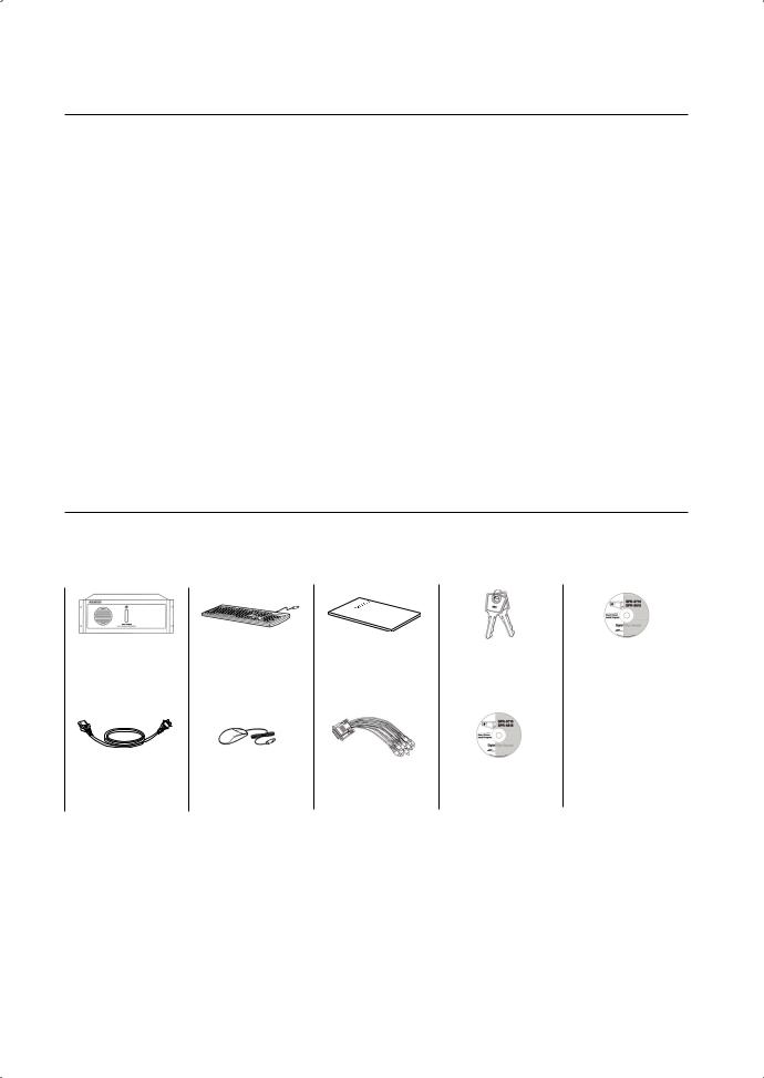
WHAT’S INCLUDED WITH YOUR DVR
Please ensure that the following components are included within the box. Contact your retailer if any of the components are missing.
|
|
|
|
|
|
|
|
|
SPR Smart System |
|
Keyboard |
|
User Manual |
|
Keys |
|
SPR Smart Viewer |
|
|
|
|
|
|
|
|
Program CD |
|
|
|
|
|
|
|
|
|
Power Cable |
|
Mouse |
|
Audio Cable |
|
System Recovery CD |
|
|
|
|
|
|
|

safety regulations
Please adhere to these safely regulations for the proper use of the product and to prevent risk/damage to you or the unit.
Do not use more than one multi-plug.
Using too many multi-plugs can cause abnormal heat generation or fire.
Do not place sources of liquids near the DVR. ie: vases, cups, medicine, etc.
Liquids can present a fire hazard.
Do not bend the power cord forcibly nor put a heavy material on it.
This action could lead to a fire.
Do not operate or setup the DVR with wet hands.
This can cause a serious injury by an electrical shock.
Firmly insert the power plug into the socket so that it does not shake.
An imperfect connection presents a fire hazard.
Protect the DVR from humidity, dust, or soot.
They can cause a fire or an electric shock.
Do not put metals (coin, hair pin, metal piece, etc.) or inflammable materials (match, paper, etc.) in the ventilation hole.
These obstructions can cause abnormal heat generation or fire.
Keep the surrounding temperature between 0°C to 40°C and keep the product off humidity.
Excessive temperatures can cause the DVR to malfunction.
Provide sufficient ventilation.
This will prevent abnormal operation due to high temperatures.
Keep the unit out of direct sunlight and away from any other sources of heat.
These sources of heat can cause abnormal heat generation or fire.
Do not disassemble, repair, or remodel the product.
This may cause fire, electric shock, or injury due to abnormal operation.
Do not pull out the power plug by the power cord.
This may destroy the power cord, eventually, cause fire or electric shock.
Unplug the unit during thunder or lightning.
A power surge can damage the unit.
Keep children away from the unit or it's components.
The unit's components present a choking hazard. Contact a doctor immediately if a component has been swallowed.
Install the product at a safe place so that there is no risk the DVR can be knocked or fall to the ground.
An insecure DVR positioning can cause physical harm or damage to the unit.
before start
This user manual provides information that are necessary in the use of the DVR, ranging from a brief introduction of the product to names, functions, and connection instructions of the components, menu configurations, and other information pertinent to product use. Please read and adhere to the following notices.
SEC retains the copyright on this manual.
This manual cannot be copied without prior written approval from the SEC.
Samsung Electronics will not be held responsible for damages caused by the improper use of the product or the use of non-specified equipment with the product.
If you want to open the case of your system for for any reason, please consult the installer or the retail outlet which you brought the product.
Source codes are available for download at: http://www.samsung.com
Check compatibility before attempting to install any internal devices (memory, HDD). A list of compatible devices can be obtained from your vendor.
WARNING
System Shutdown
Turning off the power while the product is in operation, or taking not permitted actions may cause damage to the hard drive or the product. Also it can cause a dysfunction to the system installed on the hard disk.
Please turn off the power using the Power ( /I)button on the front of your DVR. After selecting OK in the pop-up menu, you can pull out the power cord.
You may want to install a UPS system for safe operation in order to prevent damage caused by an unexpected power surge/loss. (Any questions concerning UPS, consult a UPS retailer.)
Make sure that the mains plug is not covered or obstructed by any object. The unit must be connected to an outlet with a protective ground connection.
Operating Temperature
The operating temperature range of this product is 0°C to 45°C (32°F to 113 °F). Operating the DVR outside the temperature range can cause the unit to malfunction.
If the unit was stored outside the operational temperature range, allow the unit to return to room temperature before operating.
The HDD operating temperature is 5°C (41°F) to 55°C (131°F).
The HDD like the DVR may malfunction outside of these temperatures.
STANDARDS APPROVALS
This equipment has been tested and found to comply with the limits for a Class A digital device, pursuant to part 15 of the FCC Rules. These limits are designed to provide reasonable protection against harmful interference when the equipment is operated in a commercial environment.
This equipment generates, uses, and can radiate radio frequency energy and, if not installed and used in accordance with the instruction manual, may cause harmful interference to radio communications. Operation of this equipment in a residential area is likely to cause harmful interference in which case the user will be required to correct the interference at his own expense.
The rechargeable battery incorporated in this product is not user replaceable.
For information on its replacement, please contact your service provider.

contents
introducing your real time DVR
03
installation
05
03 DVR: Front View
04 DVR: Rear view
05 Installation
connecting with other devices
06
watch
13
06 Basic connections
07 Sensor connection
08 Alarm connection
09RS485 Connection
10Network connection
11External keypad connection
12Pos device connection
13Live watch screen
14Login screen
14Camera channel
15Database drive allocation
16Resource/ptz/playback/log
18Full screen
19Live screen switch
201-Channel video playback
20Camera channel assignment
21ON-Screen keyboard
system setup
21
search
52
21System setup - Basic menu
22Hardware
29 Recording
32 Event
38Backup
39Network
43System
52Search screen
53Search date and time selection
53Timeline
54Search screen playback
54 Split-scren setupt
54 Screen adjustment
57 Event search
57 Printing
contents _01

advanced search
58
BACKUP
63
58Event search
59Sequential search
60Thumbnail search
61Object search
62Pos search
63Backup
64Backup management
appendix
65
65 System recovery
67 WebDVR
70 SPR Smart viewer
77Remote desktop control
78Specifications
79Outline drawings
80Troubleshotings(FAQ)
02_ contents
introducing your real time DVR
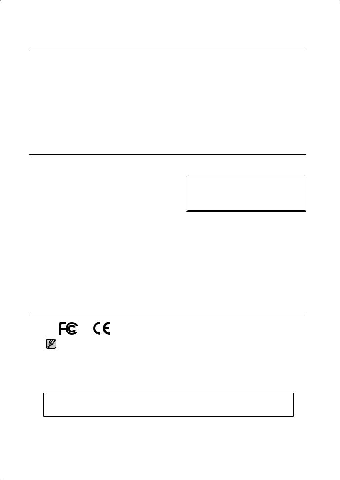
DVR: Front View
With the Panel Closed
With the Panel Open
2 3
1
1 |
Power |
2 |
USB |
3 |
DVD-RW |
|
|
Front and rear configurations of the system may change to reflect changes in specifications or other quality improvement purposes.
 DVR time real your introducing 01
introducing your real time DVR_03
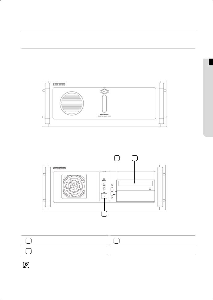
DVR: Rear View
2 |
3 |
4 |
5 |
6 |
7 |
1 |
8 |
9 |
10 |
11 |
12 |
13 |
14 |
15 |
16 |
17 |
18 |
1 |
Power Supply (AC 100-240V, 60/50Hz, 4A/2A) |
2 |
Sensor Input (Alarm-In) Ports (16 ports) |
|
|
|
|
|
|
3 |
Spot Monitor Out Ports (2 ports) |
4 |
Camera Video Input Ports (16 ports) |
|
|
|
|
|
|
5 |
RS485 Port |
6 |
Alarm-Out Ports (4 ports) |
|
|
|
|
|
|
7 |
Audio Input Port |
8 |
Mouse Input Port (PS/2) |
|
|
|
|
|
|
9 |
Keyboard Input Port (PS/2) |
10 |
Printer Port (LPT1) |
|
|
|
|
|
|
11 |
COM Port (COM1) |
12 |
Internal VGA Port |
|
|
|
|
|
|
13 |
USB Port (Ver. 2.0) |
14 |
Ethernet Port (100 Mbps) |
|
|
|
|
|
|
15 |
Microphone Input Port (two-way audio input) |
16 |
Audio Output Port (speaker connection port) |
|
|
|
|
|
|
17 |
VGA Port |
18 |
Spot Monitor Out Port (supports 16-screen) |
|
|
|
|
|
|
04_ introducing your real time DVR
installation
Checking Installation Conditions
Adhere to the following precautions when installing the unit.
•Indoor use only.
•Prevent water and liquids from coming in contact with the unit’s terminals.
•Protect the unit from excessive impact and force.
•Do not forcibly pull on the power cable.
•Do not open or disassemble the unit.
•Use within the rated power input/ output range only.
•Use an approved power cable only.
•For products that require a ground source always use a plug that includes a ground pin.
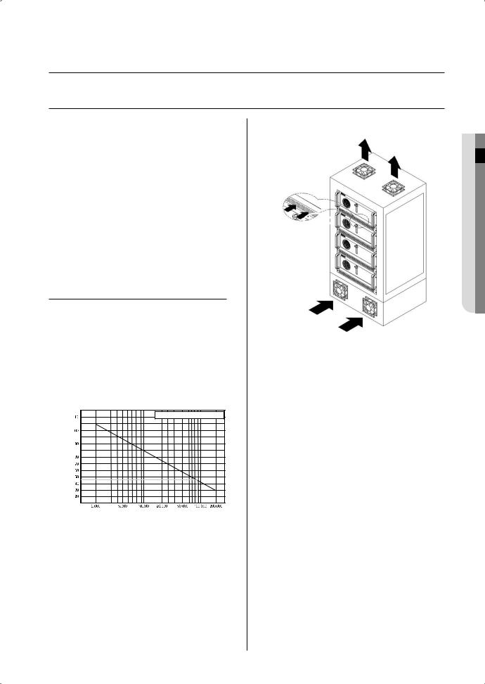
Temperature Conditions
Samsung's Digital Video Recorder is an advanced security system that contains a high-capacity hard drive and other critical circuitry.
Carefully follow the installation instructions to prevent high internal or ambient temperatures, which can lead to a shortened lifespan or malfunction of the unit.
Temperature |
One Year: 24HR X 365 DAY =8,760 HR |
|
Unit: ºC |
||
|
Life (Unit: HOURS)
[Graph: Correlation between Temperature and Product Lifespan]
Recommendations for Mounting into a Rack
1.The inside of the rack must not be enclosed.
2.The rack must feature ventilation ports to provide sufficient internal air circulation, as shown in the diagram above.
3.Allow sufficient space between the DVR unit and other modules mounted to the rack or install ventilation ports to facilitate air circulation, as shown in the diagram.
4.Install the intake ports at the bottom of the rack and exhaust ports at the top of the rack to facilitate the formation of a natural convection airflow.
5.SEC strongly recommends the installation of fans at both intake and exhaust ports. Intake fans should be installed with a filter to block dust and other foreign materials.
6.An ambient temperature range of 0˚C to +45˚C must be maintained inside the rack.
installation 02
installation _05
connecting with other devices
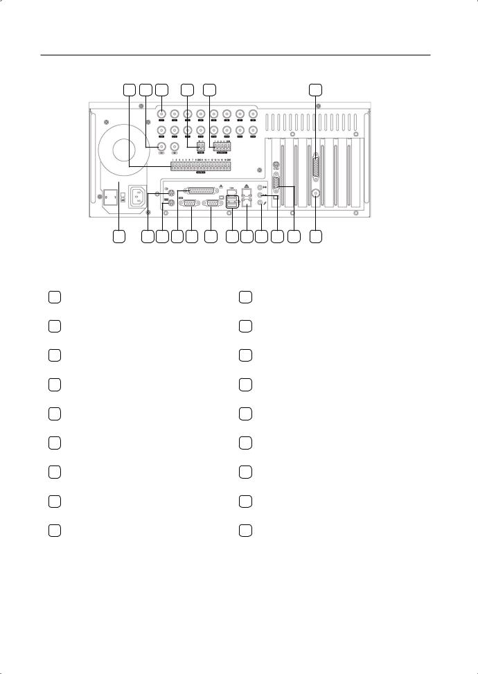
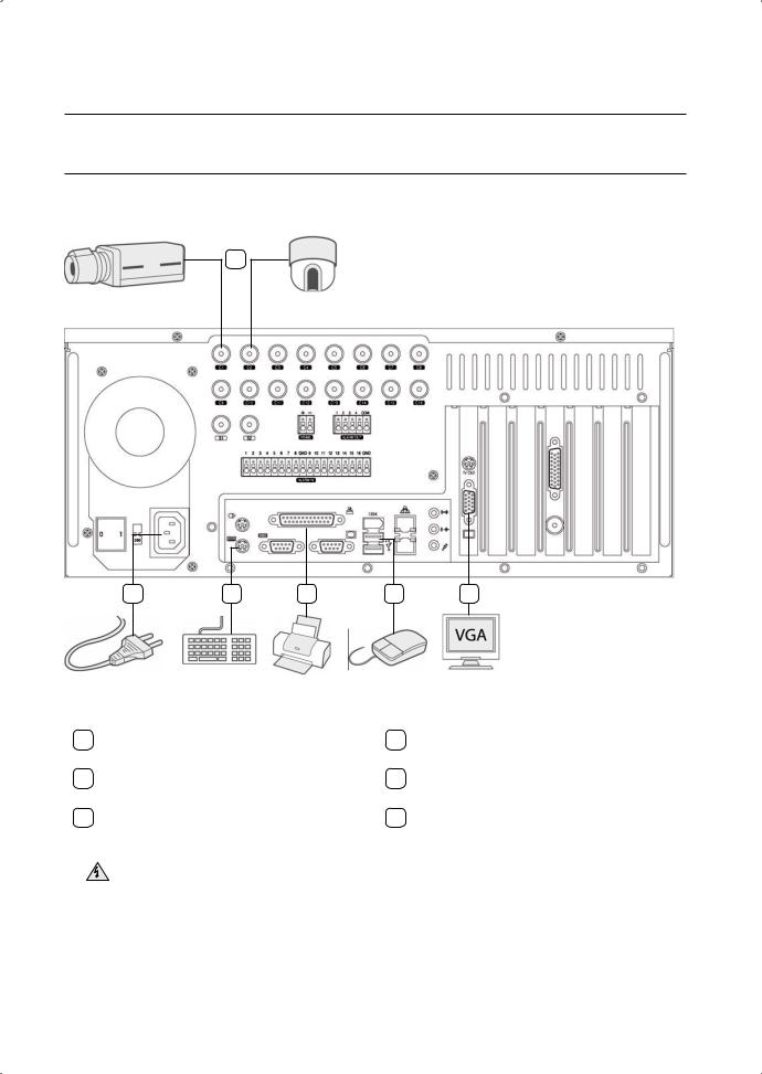
Basic Connection
1
2 |
3 |
4 |
5 |
6 |
1 |
Using a coaxial cable, connect a camera(s) to |
2 |
Attach the appropriate power cord to the |
||
the BNC port(s). |
power supply unit. |
||||
|
|
|
|||
3 |
Connect a keyboard to the PS/2 port. |
4 |
Connect a printer to the LPT1 port. |
||
|
|
|
|
|
|
5 |
Connect a mouse to a USB port. |
6 |
Connect a VGA monitor to the VGA port. |
||
|
|
|
|
|
|
|
Ensure the correct rated voltage is provided before powering the unit. Improper voltage may cause |
Warning |
malfunction and/or permanent damage to the system. |
Electrical Hazard: Please carefully read through the Safety Warnings and Precautions section. |
06_ connecting with other devices
Sensor (Alarm-In) Connection
No.1 Sensor |
|
GND |
|
No.9 Sensor |
GND |
|||
(Alarm-In) |
|
|
|
|
(Alarm-In) |
|
||
|
|
|
|
|
|
|
|
|
 devices other with connecting 02
Your DVR system is capable of transmitting electrical signals to external devices when an event occurs. Mechanical or electrical switches can be connected to the Alarm-In and Ground (GND) ports. The individual Alarm-In ports can be configured from the System Setup menu as either NC (Normal Close) or NO (Normal Open).
Alarm-In Connection
1.Connect one of the external device’s signal lines to the desired Alarm-In port.
2.Connect the remaining line to the Ground port (GND).
connecting with other devices _07
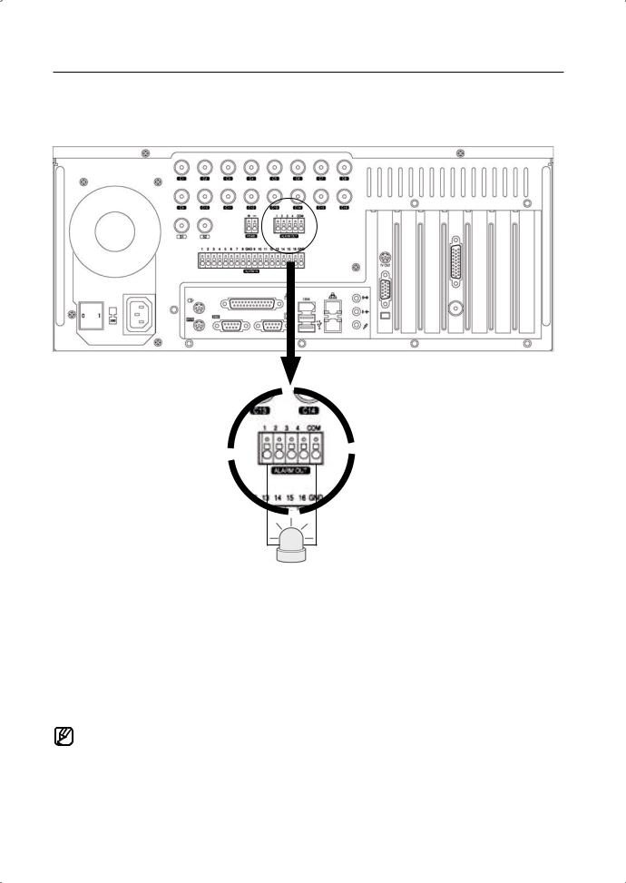
Alarm (Alarm-Out) Connection
Your DVR system is capable of activating warning lights, sirens, and other types of external devices. External device s can be connected to the unit's Alarm-Out and COM ports.
Alarm Connection
1.Connect one of the external device's signal lines to the desired alarm (Alarm-Out) port.
2.Connect the remaining line to the COM port.
•The alarms (Alarm-Out) operate in conjunction with the sensors (Alarm-In). When an event signal is received through a sensor, an electrical signal is transmitted from the corresponding alarm to activate the external device connected to that alarm.
•Alarms can be configured to function in unison with motion detection, video loss, object detection, and other software features.
08_ connecting with other devices

RS485 Connection
devices other with connecting 02
It's possible to control an external device by the DVR using the RS485 interface for communication.
The RS485 port can be used to control PTZ cameras, speed domes, keyboard controllers and other types of external devices.
Connect the RX+/TX+ & RX-/TX- of the external device to the + & - of the RS485 port respectively.
 Check the polarity (+/-) when making the connection. Faulty wiring can damage both devices. Warning Electrical Hazard: Please carefully read through the Safety Warnings and Precautions section.
It’s not possible to connect a PTZ device and a keypad device (SSC-2000) to the RS485 port and use the two devices at the same time. In order to use a PTZ device with a keypad or another type of external device, you will need to install a separate COM port expansion card.
connecting with other devices _09
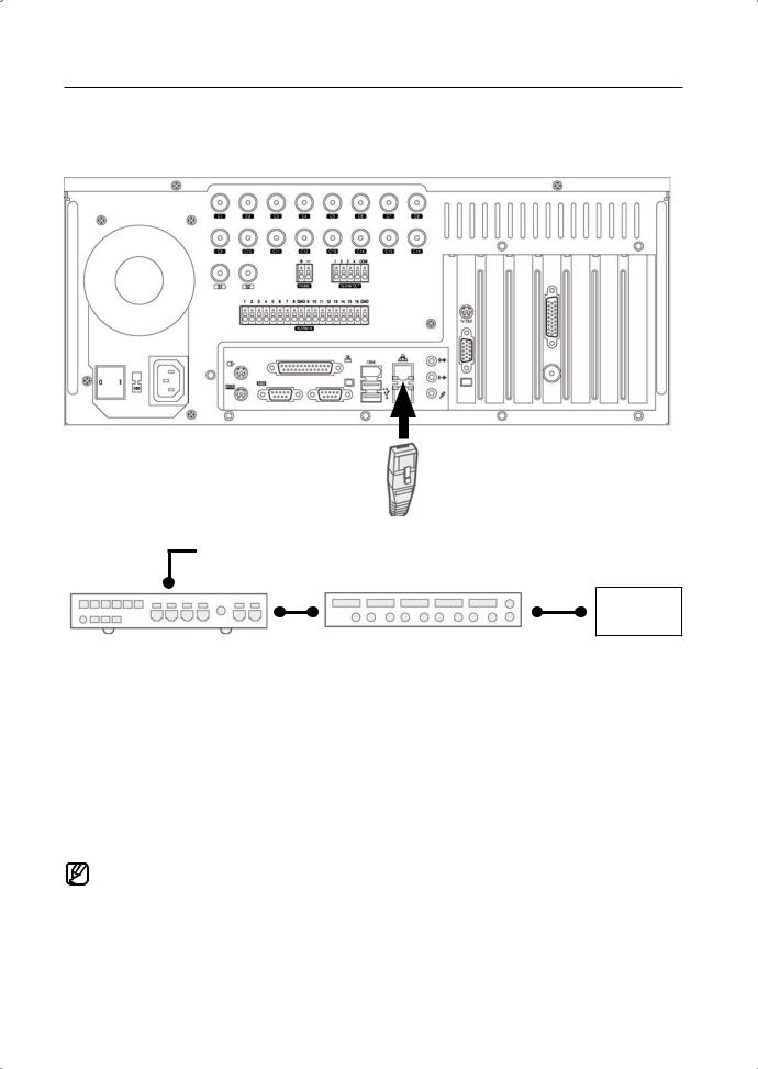
Network Connection
Ethernet/UTP Cable (CAT5) 
LAN/WAN
Internet
Switch Hub (100Mbps) |
Router |
Your DVR system supports network-based remote monitoring, remote search, remote control, and remote software upgrade. SEC recommends the use of the TCP/IP protocol and a switching hub for LAN/WAN applications.
Network Cable Connection
1.Connect a Ethernet/UTP cable to the network port located at the rear of the system.
2.Connect the opposite end of the Ethernet/UTP cable to the switch hub.
•Before connecting your DVR system to the network, please contact your network administrator to prevent the system from causing a network conflict.
10_ connecting with other devices

External Keypad Connection
devices other with connecting 02
The SSC-2000 keypad can be used to control up to 255 DVR and PTZ units.
Connect the DVR's RS485 (+/-) port to the SSC-2000 keypad's RS485 port.
•Turn the power off both units while connecting the SSC-2000.
•Pay attention to the polarity of the RS485 connections.
•Refer to the SSC-2000 manual when attempting a RS232 connection.
•When using a keypad device, please ensure that communication settings for both the DVR and the keypad device are the same. Communication settings mismatch can prevent the keypad device and the DVR from making normal communication. (Set communication protocols for both the keypad and the DVR as Half Duplex.)
•It’s not possible to connect a PTZ device and a keypad device (SSC-2000) to the RS485 port and use the two devices at the same time. In order to use a PTZ device with a keypad or another type of external device, you will need to install a separate COM port expansion card.
connecting with other devices _11

POS Device Connection
Camera
Video Input
|
|
|
|
|
|
|
|
|
|
|
|
|
|
|
POS System |
|
|
|
RS232C Cable |
|
|
V SI-PRO(Text Input Device) |
|
||||||
|
|
|
|
|
|
|||||||||
|
|
|
|
|
|
|
||||||||
|
|
|
|
|
|
|
|
|
|
|
|
|||
|
|
RS232C Cable |
|
|
|
|
|
|
|
|
Video Output |
|||
|
|
|
|
|
|
|
||||||||
|
|
|
|
|
|
|
|
|
|
|
|
|
|
|
|
|
Video Input |
|
|
|
|
|
|
|
|
|
|
||
|
|
|
|
|
|
|
|
|
|
|
|
|
|
|
RS232C Cable
Your DVR system is capable of operating in conjunction with POS systems, enabling you to store and search video transactions at the point of sale. AVE’s VSI-PRO is needed to connect the POS device to the DVR.
For details on connecting VSI-PRO with your DVR, please refer to VSI-PRO’s user manual.
•VSI-PRO by AVE (www.americanvideoequipment.com) is a device that transmits all text data received from POS device to the DVR via the RS232C interface.
•Turn off the power to all devices when connecting the POS device, VSI-PRO, and the DVR.
12_ connecting with other devices
watch
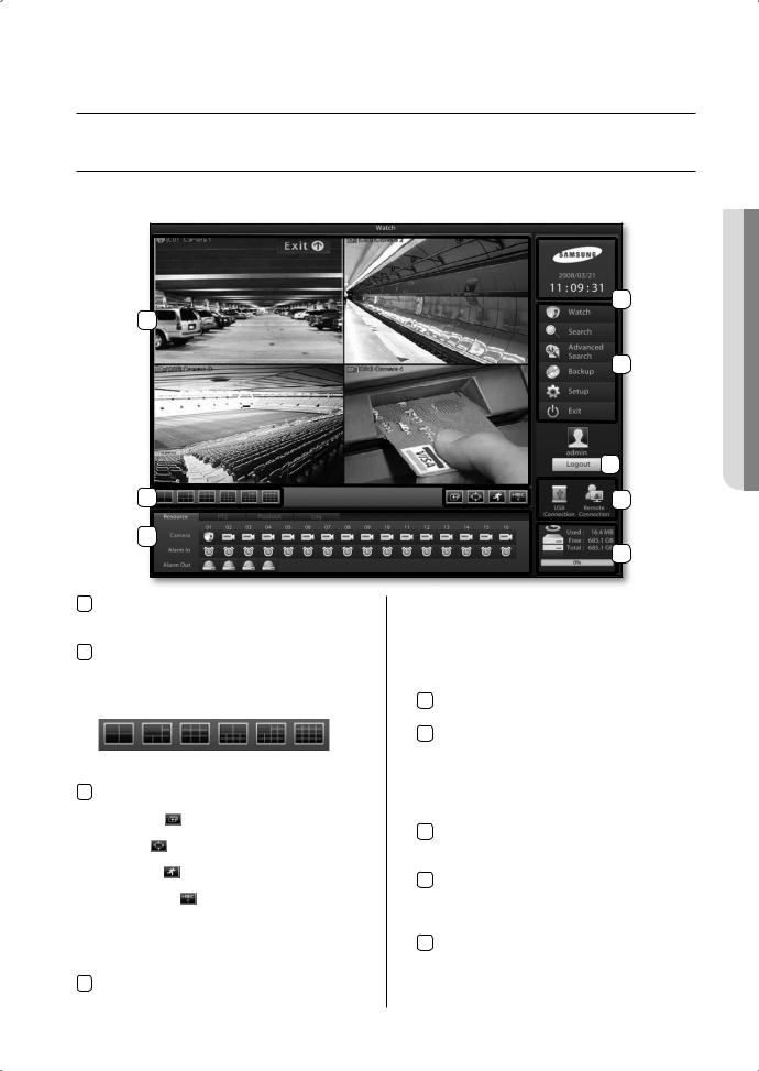
LIVE WATCH SCREEN
Live Watch supports full screen and various split-screen confi gurations. From Live Watch, you will be able to control PTZ, perform 1ch instant playback and make a backup. The buttons located within the watch screen also provide access to the other menus.(search, setup, etc).
5
1
6
7
2 |
8 |
4
9
1Video Display window
Displays the live video feeds on screen. Simply drag and drop a camera channel to move a video feed.
2Split-screen Buttons
These buttons indicate 4-, 6-, 9-, 10-, 13-, and 16-split screen modes. Continue clicking on the same mode to sequentially cycle through the other camera channels in the same split.
4- |
6- |
9- |
10- |
13- |
16- |
Screen |
Screen |
Screen |
Screen |
Screen |
Screen |
3Switch Screen/Full Screen/Switch to Live/Instant Recording.
Switch Screen( ): Automatically cycles through the video feeds.
Full Screen( ): Expands the video feeds to a full screen view.
Switch to Live( ): Reverts a 1-channel playback screen back to the live feed screen.
Instant Recording( ): Starts the instant recording of the selected channels. In the event of an emergency, clicking on this button initiates selected camera channels to start continuous recording
4Resource/pTZ/playback/Log
Resource: Select and view the status of cameras,
sensors, alarms, and other devices connected to the DVR.
PTZ: Displays PTZ controls.
Playback: Displays the controls for 1 channel playback.
Log: Displays information on the 100 most recent events that have transpired during DVR system operation.
5ClockDisplays the current time of your DVR system.
6Menu Buttons
Watch: Accesses the Live Watch screen. Search: Accesses the Search screen.
Advanced Search: Accesses the Advanced Search screen. Backup: Accesses the Backup screen.
Setup: Accesses the System Setup screen. Exit: Terminates the DVR program/system.
7Login/Logout
Launches the login window for user ID and password entry.
8USB Connection and Remote Connection
Displays the connection status of the USB storage device and the connection status of a remote PC. Blue icon indicates a connected status.
9hard Drive Capacity
Displays the total hard drive space of the system, the amount of space used, and the amount of space available.
 MONITORING 03
monitoring _13
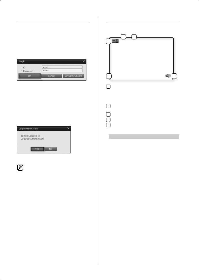
LOGIN SCREEN
Entering authorized user ID and password gives access to search features, system setup, and other system functions. Entering an incorrect user ID and password, however, will result in limited DVR functionality and control access.
Logging In
1.Click on the  button.
2.Enter the user ID and password.
3.Click OK to login.
Logging Out
1.Click on the  button.
2.Login information window will prompt displaying information about the active login account.
3.To log out from this user click the Yes button.
•From the factory, the default admin password is set as 4321.
•Admin account password cannot be changed without knowing the current admin account password; therefore, it is important that you do not lose it.
Administrators should separately record and manage their registered password.
CAmERA CHANNEL
Camera Channel Display Icons
2 3
1 |
[C01] CAMERA01 |
4 REC : M |
5 |
1Camera Type
Indicates whether the camera is a normal camera or a PTZ camera.
 : Indicates a normal camera.
 : Indicates a PTZ camera.
2Channel Number: Indicates the channel number of
the camera.
3Camera Designation: Displays the camera’s designation.
4Recording mode: Displays the camera’s recording Mode.
5Live Audio: Indicates that audio output has been
activated for the channel.
Recording modes |
On Screen Indication |
|
Not Recording |
No Indication |
|
Continuous Recording |
REC: C |
|
Motion Recording |
REC: M |
|
Object Detection |
REC: W |
|
Recording |
REC: S |
|
Sensor (Alarm-In) |
REC: P |
|
PreAlarm Recording |
REC: $ |
|
POS Recording |
||
|
||
Instant Recording |
REC: I |
|
Video Loss |
REC: L |
14_ monitoring
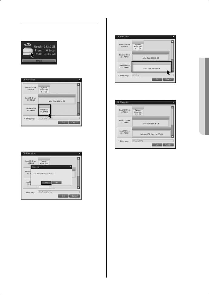
DATABASE DRIVE ALLOCATION
Allocating a New Database Drive
1.Login as an administrator then double click on the icon.
icon.
2.You will then be prompted with the Database Drive Allocation window.
3.Left-click on a non-allocated drive (Free Size) and you will be prompted with a "Do you want to format?" warning window. Click the Yes button to initiate formatting and the allocation of a new database drive.
Disabling an Allocated Database Drive
1.Right-click on the allocated drive you wish to disable. The drive color will turn from blue to grey.
2.Click OK to disable the allocated drive. The drive color will turn red.
3.Right-clicking on the disabled database drive will place the database drive in free status. Free status drives may contain data, but this data will not be recognized as database data.
 MONITORING 03
monitoring _15
Reallocating a Disabled Drive
1.Left-click your mouse on a disabled database drive and you will be prompted with a “Do you want to format?” warning window.
2.Click Yes to initiate formatting or No to bypass formatting. The drive will then be reallocated as a database drive.
RESOURCE/PTZ/PLAYBACK/LOG
Resource Tab
1
2
3
1CameraDisplays the camera status. Drag and drop a camera icon to the live screen to view the video feed from that camera.
2Alarm in
Displays the alarm-in status. A triggered channel will turn red.
3Alarm out
Displays the alarm-out status. An activated alarm will turn red.
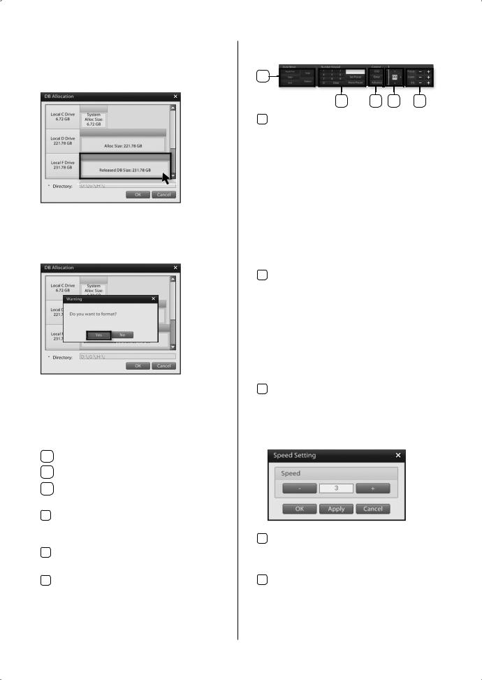
PTZ Tab
1 |
|
|
|
2 |
3 |
4 |
5 |
1Auto move
Automated PTZ movement functions.
Auto Pan: This button is used to initiate Auto Pan. AutoPan is a function where, after designating the start point and end point, the camera completes pan/tilt trips within the defi ned interval.
Start: Starting position for the Auto Pan. End: Ending position for the Auto Pan.
Scan: Seeks out presets containing PTZ position data and moves to the position stored in memory.
Pattern: Memorizes observation trajectories initiated by the user and then automatically moves the camera in the same pattern and speed.
2Preset
Enables the user to define Pan/Tile positions and Zoom/Focus settings under Preset IDs that can be used on demand. The number of supported presets varies depending on the PTZ model. The system supports up to the number of presets supported by the PTZ itself.
Numeric Keypad: Use to enter Preset numbers. Set Preset: Use to assign a PTZ camera position to a specified Preset ID.
move Preset: Moves the PTZ camera to the position specified by a Preset ID.
3Control
OSD: Accesses the PTZ camera's OSD menu. Enter: Confi rms selections in the PTZ camera's
OSD menu.
Advanced: Accesses the PTZ camera's speed confi guration window.
4Directional Pad
Controls the vertical, horizontal, and diagonal movement of the PTZ camera. Also used to navigate in the PTZ camera's OSD menu.
5Focus/Zoom/Iris
Controls the PTZ camera's focus, zoom, and iris.
16_ monitoring
Playback Tab
Click on the Playback tab to access recording timelines and recording playback controls for 1ch playback.
3
1
2
4 |
5 |
6 |
7 |
1RefreshRefreshes the timeline to the latest recording data.
2CameraDisplays the selected video channel. Selecting the camera will display the corresponding time line data.
3Date & Time Selection
Select the desired year, month, and date to search.
4Timeline
Timeline features fi ve levels of zoom. The zoom feature can be used view the time line in more detail. Left-click on the timeline to zoom-in. Rightclick on the time line to zoom-out.
5Recorded Data Time line
Displays recording times and types in a colored time line.
Orange |
Continuous Recording |
|
|
Blue |
Motion Recording |
|
|
Grey |
Object Detection Recording |
|
|
Green |
Alarm in Recording |
|
|
Yellowish Green |
PreAlarm Recording |
|
|
Dark Blue |
ATM/POS Recording |
|
|
Yellow |
Video Loss |
|
|
Purple |
Instant Recording |
|
|
6Timeline Bar
Identifies the location of the desired timeframe you wish to search. Click the bar to the desired time.
7Playback Controls
Controls the direction and speed of the video playback.
First recorded Data
Single Frame Reverse
Reverse Playback
Forward Play
Stop
Single Frame Forward
Last recorded Data
1x Playback
Slow Fast
Maximum
Speed
Mute
High Volume
•Audio output is only available for 1x forward playback.
Log Tab
Clicking on the Log tab accesses event detection details, such as recording type (continuous, motion, object detection, PreAlarm, and POS) and network connection status.
 MONITORING 03
monitoring _17

FULL SCREEN
Switching to Full Screen
1. Click on the button to expand the live video to full screen.
2.You now have full screen view of the live video feeds.
3.Click on the left mouse button to end full screen display.
LIVE SCREEN SWITCH
This feature enables you to fl ip through different camera feeds. If all camera feeds are not visible on a single screen, use this feature to fl ip through and view the remaining channels in sequence.
Sequencing Button
1.Select a single-screen or a 4-, 6-, 9-, 10-split screen, mode then click on the button.
2.The system will cycle through video feeds while maintaining the selected display mode.
13 |
14 |
|
9 |
10 |
|
5 |
6 |
13~16 |
1 |
2 |
9~12 |
|
||
|
|
5~6 |
3 |
4 |
1~4 |
|
|
4-Channel Split Screen
10 |
11 |
|
12 |
|
1 |
2 |
3 15 |
|
|
4 |
5 |
6 18 |
10~18 |
|
7 |
8 |
9 |
1~4 |
|
9-Channel Split Screen
3. Click on the button to stop the cycling.
18_ monitoring
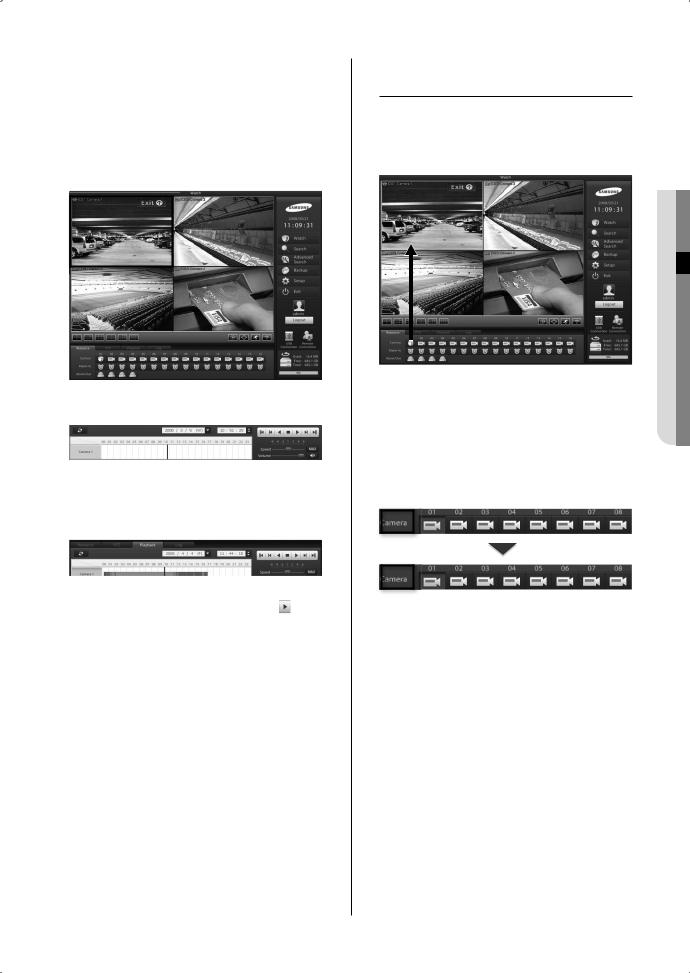
1-CHANNEL VIDEO PLAYBACK
Instant 1-channel playback of the selected channel while monitoring others on live video feed.
1-Channel Playback
1.While monitoring, select a camera feed you wish to playback.
2.Click on the playback tab.
3.Click on the camera  button.
4.The recording time line data of the selected channel will be displayed.
5.Select the playback time and click on the button to start playback.
6.Click on the  button to exit the 1-channel playback.
CAmERA CHANNEL
ASSIGNmENT
Assigning a Camera Channel
1.Click on a camera button using your mouse and drag to the live screen.
MONITORING 03
2.After dragging to live screen drop over the desired location on live screen to assign that channel.
Reset the video feed layout
The camera designations will turn from white to brown if reassigned video channels are preventing other channels from being displayed or if the video channel sequence is mixed up.
1. To reset the cameras to their default locations double-click on  .
.
monitoring _19
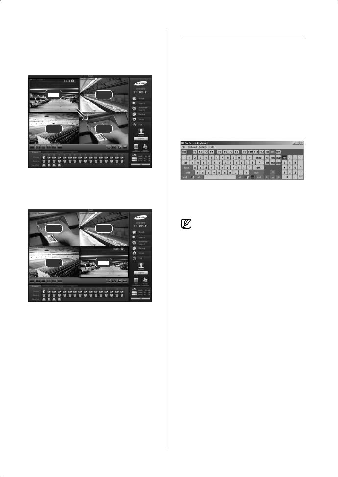
moving Camera Picture Via View Panel
1.Click on a video feed and drag to the desired location.
Ch 2
Ch 3 |
Ch 4 |
2.Release the mouse button over the desired location to complete the camera feed movement.
Ch 4 |
Ch 2 |
Ch 3
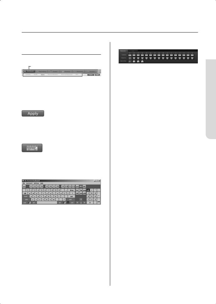
ON-SCREEN KEYBOARD
A virtual keyboard can be displayed on screen. This On-Screen Keyboard allows the user to directly enter text using the mouse when there is no keyboard attached to the DVR system or when using a keyboard is not a viable option.
Launching the On-Screen
Keyboard
1.Click on the  button to launch the virtual keyboard.
2.Using your mouse, click on the characters of the virtual keyboard to make key entries.
3.To terminate On-Screen Keyboard, either click on File then select Exit or click the button.
•The virtual keyboard supports only the English language option.
20_ monitoring
System Setup
System Setup - Basic
Menu
Setup menu category buttons
Main Menu
 Sub Menu
Select from individual system setup categories.
The main setup categories are Hardware, Recording,
Event, Backup, Network, and System.
Saving Changes
Apply: Applies any change that has been made in the system setup.
Virtual Keyboard
Click on the  button to launch the virtual keyboard.
With the virtual keyboard, key entries can be made using the mouse.
Camera/Alarm In/Alarm
Camera: Use to select cameras you wish to configure.
Alarm In: Use to select sensors (Alarm In) you wish to configure.
Alarm: Use to select alarms (Alarm Out) you wish to configure.
 Setup System 05
System Setup _21
HARDWARE
This category applies to the external devices that form your DVR system. External devices like cameras, audio devices, sensors, alarms, monitors, keyboards, and POS devices Setup. These options can be used to confi gure a security system to meet your operating environment.
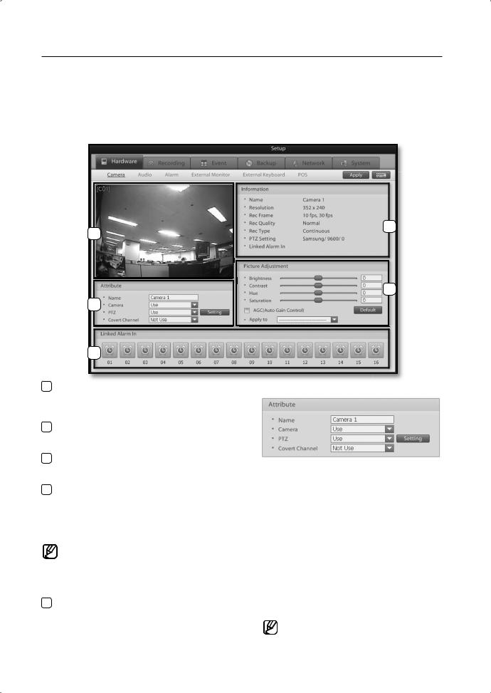
Camera
Use this menu to enable/disable individual cameras and to confi gure the brightness, contrast, hue, and saturation levels of the video source. In addition, select whether to enable PTZ use and assign covert attributes to video feeds.
2
1
4
3
5
1 |
Video Display window |
|
Camera Attribute |
|
|||
|
Displays the selected camera video feed. |
|
|
|
Changes to camera settings can be verifi ed from |
|
|
|
this window. |
|
|
2 |
Information |
|
|
|
Displays information about the selected camera |
|
|
|
channel. |
|
|
3 |
Attribute |
|
|
|
Confi gure the camera name, mode, PTZ setting, |
|
Name: Enter a name (Suggestion: Camera location). |
|
and covert channel. |
|
Camera: Enable or disable the selected camera. |
4 picture Adjustment |
|
||
|
PTZ: Enable or disable PTZ use for the selected |
||
|
Use this feature to adjust the video signal's brightness, |
|
|
|
|
camera. |
|
|
contrast, hue, and saturation levels. Clicking on the |
|
|
|
|
Setting: Click the setting button to access PTZ |
|
|
Default button will return all settings to default. Automatic |
|
|
|
Gain Control is a feature that automatically adjusts the |
|
protocol setup and communication |
|
brightness level for the camera. |
|
confi guration options. |
|
The screen adjustment functions cannot be |
|
Covert Channel: Enable or disable Covert Channel |
|
|
option for the selected camera. |
|
|
expected to improve the quality on a low |
|
|
|
|
Covert Channel is a feature that |
|
|
quality video signal. Also make sure that |
|
|
|
|
hides the selected camera's video |
|
|
the camera and monitor have been setup |
|
|
|
|
feed. This feature is particularly |
|
|
correctly before making video adjustments. |
|
|
|
|
useful when you don’t want selected |
|
|
Linked Alarm In |
|
|
5 |
|
users/people to view the camera |
|
Select which sensor to link with the selected |
|
feed, recording or location. |
|
|
camera. When an event is detected, the selected |
|
When monitoring video feeds from a |
|
sensor will initialize the camera to commence |
|
|
|
|
remote location, covert video feeds are |
|
|
video recording. |
|
|
|
|
viewable by authorized users. |
|
|
|
|
|
22_ System Setup |
|
|
|
|
|
||
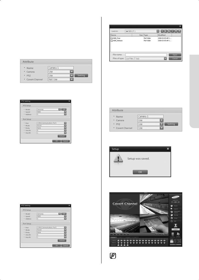
This DVR system allows you to remotely control PTZs, speed domes, and other external devices connected to the system. Before using this feature, however, you must install the external device to the RS485 port and configure the external device settings.
PTZ Setup
1.To select a camera for PTZ control set the PTZ option to Use.
2.Click on the Setting button to access the following window:
3.Define the model, baudrate, address, and communication method of the PTZ installed to the DVR.
4.Click on the OK button to finish configuring the PTZ.
Add to PTZ List
1. To add a new PTZ model, click on the Add button:
2. |
Select the PTZ model you wish to add. |
|
|
|
|
|
|
05 |
|
|
|
|
|
|
3. |
Click on the Open button to register the selected |
System |
|
|
|
|
|||
|
PTZ model. |
|
|
|
Covert Channel Setup |
Setup |
|
||
|
||||
|
|
|||
1. |
Select the camera channel you wish to set as a |
|
|
|
|
Covert Channel. |
|
|
|
2. |
Set Covert Channel option to Use. |
|
|
|
3. |
Click on the Apply button and then, when the |
|
|
|
|
|
|||
|
following window prompts, click on the OK button. |
|
|
|
|
|
|
|
|
|
|
|
|
|
4.The covert channel sign will be shown instead of a video feed on the display screen.
The video feeds will be shown when logged in as a user with secure channel permission.
System Setup _23
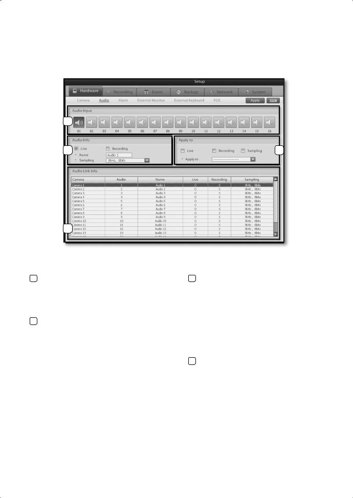
Audio
Use this menu to enable/disable live audio output and audio recording.
1
2 |
3 |
4
1 |
Audio Input |
3 |
Apply to |
|
This menu allows you to associate individual |
|
Live: Select this option if you want to apply the |
|
audio input channels to each camera channel. |
|
current live option settings to all or selected |
|
Select a camera channel and then the audio input |
|
camera channels. |
|
channel you wish to associate to the selected |
|
Recording: Select this option if you want to apply |
|
|
the current recording option settings to |
|
|
camera channel. |
|
|
|
|
all or selected camera channels. |
|
2 |
Audio Setup |
|
|
|
Sampling: Select this option if you want to apply |
||
|
Live: Enables/disables live audio output on the live |
|
the current sampling settings to all or |
|
screen. |
|
selected camera channels. |
|
Recording: Enables/disables audio recording. |
|
Apply to: Implements the setting changes for the |
|
Name: Enter the name of the audio channel. |
|
selected options to all or selected camera |
|
Sampling: Select the desired recording sampling |
|
channels. |
|
rate. |
4 |
Audio Link Info |
|
|
||
|
|
|
Displays the audio properties of each camera |
|
|
|
channel. |
|
|
|
|
24_ System Setup

Alarm
This setup category covers sensor, camera, and alarm association settings. By associating a camera to a sensor, you can confi gure how long the camera is going to record for when a sensor event is detected. In addition, by associating an alarm output to a sensor, you can setup the alarm output to sound a warning signal when a sensor event is detected.
1
2
3
4
1 |
Setting |
3 |
Type |
|
Channel: Select the sensor you wish to confi gure. |
|
Select the input type of the sensor. |
|
Name:Enter the name of the sensor. |
|
Click the button to switch between the NC and |
|
Pre rec time: Select the time prior to a sensor event |
|
NO option. |
|
that the camera should record. |
|
: Normally open, but closes when an event is |
|
Post rec time: Select the time after to a sensor |
|
|
|
|
detected (Normally Open). |
|
|
event that the camera should record. |
|
|
|
|
: Normally closed, but opens when an event is |
|
|
Full Screen: Make the linked camera channels pop- |
|
|
|
|
detected (Normally Close). |
|
|
up full screen on the display screen |
|
|
|
|
|
|
|
when a sensor event occurs. |
4 |
Alarm Out |
|
Dwell Time: This option is used to defi ne for how long |
|
Channel: Select an alarm (Alarm Out) to associate |
|
subsequent sensor event signals are |
|
to the sensor (Alarm In). |
|
ignored after an initial event signal. Enabling |
|
Name: Enter the name of the alarm. |
|
this option instructs the system to ignore |
|
Dwell Time: Set how many seconds the alarm will |
|
all other event signals transmitted by the |
|
be active on a sensor event. |
|
sensor for the set amount of time following |
|
Alarm Out Button: Select a sensor channel to |
|
the initial event signal. So once an event |
|
associate to the alarm. |
|
signal is transmitted, the set discard time |
|
: Indicates an associated sensor. |
|
must lapse before another event signal can |
|
|
|
|
: Indicates a non-associated sensor. |
|
|
be recognized. |
|
|
2 |
Linked pTZ |
|
|
|
Camera: Select the PTZ camera channel you wish |
|
|
|
to associate to the sensor. |
|
|
|
Preset: Select the PTZ preset for when the sensor |
|
|
|
event is detected. |
|
|
|
Spot Full up: Select the camera channel to be |
|
|
|
displayed full screen on the spot |
|
|
|
monitor in a sensor alarm event. |
|
|
|
Dwell Time: Set the time that the camera is |
|
|
|
displayed on the spot monitor. |
|
|
|
|
|
|
 SETUp SYSTEM 05
System Setup _25
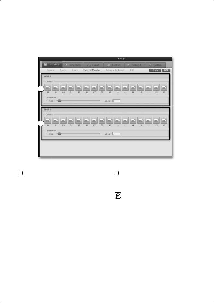
External monitor
This menu directs video feeds to an external monitor via the spot port. Select the cameras to be display on the spot and confi gure their dwell time.
1
2
1 SpOT 1 |
2 SpOT 2 |
Camera: Select camera feeds to be transmitted by |
Camera: Select camera feeds to be transmitted by |
spot port 1. |
spot port 2. |
Dwell Time: Drag the slider left or right to set the |
Dwell Time: Drag the slider left or right to set the |
delay interval between screen changes. |
delay interval between screen changes. |
|
Channels confi gured as a Covert Channel |
|
cannot be displayed on the spot monitor. |
|
|
26_ System Setup
 Loading...