


16 Channel DVR
SHR-4160N/P User’s Manual

SHR-4160N/P USER’S MANUAL
Safety Regulations
Please be sure to keep the following in mind for the right use of the product to
pre-vent proprietary risk or damage.
■Do not use multiple plugs at once.
●This may cause abnormal heat generation or fire
■Do not put a vase, flowerpot, cup, cosmetics, medicine, or vessel with water around you.
●This may cause fire.
■Do not bend the power cord forcibly nor put a heavy material on it.
●This may cause fire.
■Do not touch the power plug with wet hands.
●This may cause electric shock.
■Insert the power plug firmly enough not to shake.
●This imperfect connection may cause fire.
■Keep the product off humidity, dust, or soot.
●This may cause fire or electric shock.
■Do not put metals(coin, hair pin, metal piece, etc.) or inflammable materials(match, paper, etc.) in the ventilation hole.
●This may cause fire.
■Keep the surrounding temperature between 0˚C to 40˚C and keep the product off humidity.
●This may cause breakdown.
■Secure sufficient ventilation.
●This may cause abnormal operation due to high temperature.
■Keep the product off direct ray of light or heat from the heating device
●This may cause fire.
■Do not disassemble, repair, or remodel the product.
●This may cause fire, electric shock, or injury due to abnormal operation.
■Do not pull out the power cord.
●This may destroy the power cord, eventually, cause fire or
electric shock.
■ Plug out in the event of thunder or lightning.
● This may cause fire.
■Keep your children off the battery after you take it out of the product. They tend to swallow it unconsciously.
●If your children swallow it, please see the doctor immediately.
■Install the product at a safe place or attach the product to the wall or ceiling with a stand firmly enough not to fall to the ground.
●This may injure people.
ii

Before we start
This User’s Manual describes the basic usage of SHR-4160N/P. This Manual contains all the matters necessary for using SHR-4160N/P such as brief instruction, part name, function, connecting other equipment, and menu setup of SHR-4160N/P.
-SEC retains the copyright on this User’s Manual.
-This User’s Manual cannot be copied without SEC’s prior written approval.
-We are not liable for any or all losses to the product incurred by your use of nonstandard product or violation of User’s Manual.
-If you want to open the system case to touch the inside, please consult with an expert who works for the shop where you bought the product.
-You may download open source codes from the following website. (See CCTV Part of http://www.sec.co.kr)
WARNING
[Battery]
As wrong exchange of the battery in SHR-4160N/P may cause explosion, you shall use the certified battery for SHR-4160N/P.
The battery specification is as follows.
-Normal Voltage: 3V
-Normal Capacity: 220mAh
-Continuous Standard Load: 0.2mA
-Operating Temperature: -30 ~ +60˚C
[System Shutdown]
- Power-off without terminating the system in the System Shutdown menu may incur
improper motion like |
data loss |
and |
disk failure |
. Power-off shall be done in the |
System Shutdown menu. |
|
|
|
|
Standards Approvals
Note : This equipment has been tested and found to comply with the limits for a Class A digital device, pursuant to part 15 of the FCC Rules. These limits are designed to provide reasonable protection against harmful interference when the equipment is operated in a commercial environment. This equipment generates, uses, and can radiate radio frequency energy and, if not installed and used in accordance whit the instruction manual, may cause harmful interference to radio communications. Operation of this equipment in a residential area is likely to cause harmful interference in which case the user will be required to correct the interference at his own expense.
iii

Contents
iiSafety Regulations Before we start Standards Approvals
|
Chapter 1 Overview |
|
1-1 |
1. |
Introduction |
1-2 |
2. |
Features |
1-3 |
3. |
Part Names and Functions |
2 |
Chapter 2 Installation |
|
2-1 |
1. |
Installation Environment Setup |
2-2 |
2. |
Checking Product & Accessories |
2-3 |
3. Additional HDD Installation |
|
3 |
Chapter 3 Connecting with Other |
|
|
|
Equipment |
3-1 |
1. |
Connecting Video, Audio, & Monitor |
3-2 |
2. |
Connecting Network |
3-3 |
3. |
Connecting IEEE1394 Device |
3-5 |
4. |
Connecting USB Device |
3-6 |
5. |
Connecting Alarm Input/Output |
3-8 |
6. |
Connecting RS-485 Device |
4 |
Chapter 4 Live |
|
4-1 |
1. |
System Motion |
4-2 |
2. |
Live Screen Mode |
4-5 |
3. |
Live Channel Selection and Audio On/Off |
|
|
Setup |
4-6 |
4. |
Freeze and Zoom |
4-7 |
5. |
Event Monitoring |
4-8 |
6. |
Spot-out Monitoring |
iv

5 |
|
5 Menu Setup |
5-1 |
Before Use |
|
5-2 |
1. |
System |
5-12 |
2. |
Camera |
5-16 |
3. |
Monitoring |
5-18 |
4. |
Record Mode |
5-19 |
5. |
Event Record Mode |
5-24 |
6. |
Record Schedule |
5-26 |
7. |
Backup |
5-28 |
8. |
Network |
5-32 |
9. |
Network Setup |
6 |
Chapter 6 PTZ Device Control |
|
6-1 |
1. |
PTZ device Control Mode |
6-3 |
2. |
Basic Operation of PAN, TILT, & ZOOM |
6-4 |
3. |
PRESET Setup |
6-6 |
4. |
Camera Menu Setup |
6-7 |
5. |
Preset View |
6-8 |
6. |
Other Views |
7 |
Chapter 7 Recording |
|
7-1 |
1. |
PANIC (Emergency Recording) |
7-2 |
2. |
REC (Normal Recording) |
7-3 |
3. |
Record Schedule |
7-4 |
4. |
Event Recording |
8 |
Chapter 8 Search & Play |
|
8-1 |
Before Use |
|
8-2 |
1. |
Calendar Search |
8-3 |
2. |
Event Search |
8-4 |
3. |
Date/Time Search |
8-5 |
4. |
Go to First Search |
8-6 |
5. |
Go to Last Search |
8-7 |
6. |
Play |
v

9 |
|
Back up Search |
9-1 |
1. |
Backup |
9-4 |
2. |
Backup Search |
10 |
Chapter 10 Smart Viewer |
|
10-1 |
1. |
Introduction |
10-2 |
2. |
Feature |
10-3 |
3. |
PC Specification(Recommendation) |
10-4 |
4. |
Smart Viewer Installation |
10-7 |
5. |
Smart Viewer Program Execution |
10-8 |
6. |
Smart Viewer Initial Screen |
10-9 |
7. |
Monitoring Mode |
10-23 |
8. |
Search Mode |
10-30 |
9. |
SETUP MODE |
11 |
Backup Viewer |
|
11-1 |
1. |
Introduction |
11-2 |
2. |
Features |
11-3 |
3. |
PC Specification(Recommendation) |
11-4 |
4. |
Backup Viewer Installation |
11-8 |
5. |
Executing Backup Viewer Program |
11-9 |
6. |
Initial Screen of Backup Viewer |
11-10 |
7. |
Using Backup Viewer |
12 |
Appendix |
|
12-1 |
1. |
Product Specification |
12-4 |
2. |
HDD Specifications |
12-5 |
3. |
Outline Drawing |
12-6 |
4. |
Factory Default |
12-8 |
5. |
SHR-4160N/P Smart Viewer Play Frame Specification |
12-10 |
6. Troubleshooting(FAQ) |
|
vi


Chapter 1 Overview
1

SHR-4160N/P USER’S MANUAL
Video Recorder(DVR) compresses the camera input data from 16
a MPEG4 video file and the voice input data into a G.726 audio file to record them in the Hard Disk or retrieve them from the Hard Disk
.
it transmits the video or audio file out through a network on real time basis can monitor either file remotely by your PC.
1-1

2Features
■
■
■
■
■
■
■
■
■
■
■
■
■
16 CH Composite Input Connectors
NTSC/PAL Video Source Compatible
Able to record the CIF size (NTSC : 352 x 240 / PAL : 352 x 288) video image at the speed of 360ips(NTSC) / 300ips(PAL)
16 CH Loop Through Video Connectors
Hard Disk Overwrite Mode
Large quantity HDD backup function by using IEEE1394 and USB2.0, USB2.0 Memory, Backup function by using an external CD/DVD writer.
Able to record, play, and transmit both audio and video files to Windows Network Viewer(Smart Viewer) simultaneously
Able to reacord and replay 8 channels of Audio
Variable Search Mode (Time/Date, Event, Camera)
Variable Recording Mode (Time Lapse, Event, Schedule, Emergency) Extended Hard Disk Connection (IEEE1394, USB2.0)
Alarm Interface (Input:16, Output:4, Reset:1)
Remote Monitoring by Windows Network Viewer(Smart Viewer)
1-2
SHR-4160N/P USER’S MANUAL
3Part Names and Functions
|
|
|
|
|
|
|
|
|
|
|
|
|
|
|
|
|
|
|
|
|
|
|
|
|
|
|
|
|
|
|
|
|
|
|
|
|
|
|
|
|
|
|
|
|
|
|
|
|
|
|
|
|
|
|
|
|
|
|
|
|
|
|
|
|
|
|
|
|
|
|
|
|
|
|
|
|
|
|
|
|
|
|
|
|
|
|
|
|
|
|
|
|
|
|
|
|
|
|
|
|
|
|
|
|
|
|
|
|
|
|
|
|
|
|
|
|
|
|
|
|
|
|
|
|
|
|
|
|
|
|
|
|
|
|
|
|
|
|
|
|
|
|
|
|
|
|
|
|
|
|
|
|
|
|
|
|
|
|
|
|
|
|
|
|
|
|
|
|
|
|
|
|
|
|
|
|
|
|
|
|
|
|
|
|
|
|
|
|
|
|
|
|
|
|
|
|
|
|
|
|
|
|
|
|
|
|
|
|
|
|
|
|
|
|
|
|
|
|
|
|
|
|
|
|
|
|
|
|
|
|
|
|
|
|
|
|
|
|
|
|
|
|
|
|
|
|
|
|
|
|
|
|
|
|
|
|
|
|
|
|
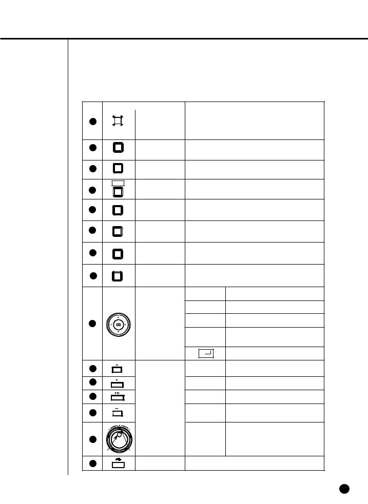
No |
|
|
|
|
|
|
Name |
|
|
|
|
|
|
|
Function |
|||||||||||||
|
|
|
|
|
|
|
|
|
|
Power LED |
Displays power on/off condition. |
|||||||||||||||||
|
|
|
|
|
|
|
|
|
|
|
|
|
|
|
|
|
|
|
|
|
|
|
|
|
|
|
|
|
|
|
|
|
|
|
|
|
|
|
Network LED |
Displays both network connection and data transmis- |
|||||||||||||||||
|
|
|
|
|
|
|
|
|
|
sion conditions. |
|
|
|
|
|
|
|
|
|
|
||||||||
|
|
|
|
|
|
|
|
|
|
|
|
|
|
|
|
|
|
|
|
|
|
|
||||||
|
|
|
|
|
|
|
|
|
|
|
|
|
|
|
|
|
|
|
|
|
|
|
|
|
|
|
|
|
1 |
|
|
|
|
|
|
|
|
Back Up LED |
Displays Back Up Mode. |
||||||||||||||||||
|
|
|
|
|
|
|
|
|
|
|
|
|
|
|
|
|
|
|
|
|
|
|
|
|
|
|
|
|
|
|
|
|
|
|
|
|
|
|
HDD Access |
Indicates Normal Access to HDD. |
|||||||||||||||||
|
|
|
|
|
|
|
|
|
|
LED |
Upon Access to HDD, LED repeats on and off. |
|||||||||||||||||
|
|
|
|
|
|
|
|
|
|
|
|
|
|
|
|
|
|
|
|
|
|
|
|
|
|
|
|
|
|
|
1 |
|
|
16 |
|
|
|
|
|
Selects Single Channel in the Display Mode. |
|||||||||||||||||
2 |
|
|
|
... |
|
|
|
Channel Button |
||||||||||||||||||||
|
|
|
|
|
|
|||||||||||||||||||||||
|
|
|
|
|
|
Used for Number Input Button in the Number Input Mode. |
||||||||||||||||||||||
|
|
|
|
|
|
|
|
|
|
|
|
|
|
|
|
|
|
|
|
|
|
|
|
|
|
|
|
|
|
|
|
|
16 |
|
|
|
|
Audio Setup |
|
|
|
|
|
|
|
|
|
|
|
|
|
|
|
|
|||
3 |
|
|
|
|
|
|
|
|
|
Audio On/Off setup during play mode. |
||||||||||||||||||
|
|
|
|
|
|
|
|
|||||||||||||||||||||
|
|
|
|
|
|
|
|
|||||||||||||||||||||
|
|
|
|
|
|
|
|
|
Button |
|||||||||||||||||||
|
|
|
|
|
|
|
|
|
|
|
|
|
|
|
|
|
|
|
|
|
|
|
|
|
|
|||
|
|
|
|
|
|
|
|
|
|
|
|
|
|
|
|
|
|
|
|
|
|
|
|
|
||||
|
|
|
|
|
|
|
|
|
|
|
|
|
|
|
|
|
|
|
|
|
|
|
|
|
||||
|
|
|
|
|
|
|
|
|
|
|
|
|
|
|
|
|
|
|
|
|
|
|
|
|
|
|
|
|
|
|
|
|
|
|
|
|
|
|
|
|
|
|
|
|
|
|
|
|
16 Displays Split Screen. |
||||||||
|
|
|
|
|
|
|
|
|
|
|
|
|
|
|
|
|
|
|
|
|
||||||||
|
|
|
|
|
|
|
|
|
|
|
|
|
|
|
|
|
|
|
|
9 Displays Split Screen. |
||||||||
|
|
|
|
|
|
|
|
|
|
|
|
|
|
|
|
|
|
|
|
|
|
|
|
|
|
|
|
|
|
|
|
|
MODE |
|
|
|
|
Split Screen |
|
|
|
|
|
|
|
4 Displays Split Screen. |
|||||||||||
|
|
|
|
|
|
|
|
|
|
|
|
|
|
|
||||||||||||||
|
|
|
|
|
|
|
|
|
|
|
|
|
|
|
||||||||||||||
|
|
|
|
|
|
|
|
|
|
|
|
|
|
|
|
|
|
|
|
|
|
|
|
|||||
|
|
|
|
|
|
|
|
|
|
|
|
|
|
|
6 Displays Split Screen. |
|||||||||||||
|
|
|
|
|
|
|
|
|
|
|
|
|
|
|
|
|
||||||||||||
|
|
|
|
|
|
|
|
|
|
Button |
Mode |
|
|
|
|
|
7 Displays Split Screen. |
|||||||||||
|
|
|
|
|
|
|
|
|
|
|
|
|
|
|
||||||||||||||
|
|
|
|
|
|
|
|
|
|
|
|
|
|
|
|
|
8 Displays Split Screen. |
|||||||||||
|
|
|
|
|
|
|
|
|
|
|
|
|
|
|
|
|
|
|
|
|
|
|
|
|
|
|
|
|
|
|
|
|
|
|
|
|
|
|
|
|
|
|
|
|
|
|
|
|
Displays PIP(Picture In Picture) |
||||||||
|
|
|
|
|
|
|
|
|
|
|
|
|
|
|
|
|
|
|
|
Screen. |
||||||||
|
|
|
|
|
|
|
|
|
|
|
|
|
|
|
|
|
|
|
|
Screen change Mode : |
||||||||
|
|
|
|
|
|
|
|
|
|
|
|
|
|
|
|
|
|
|
|
Enters Single Channel Screen |
||||||||
|
|
|
|
|
|
|
|
|
|
|
|
|
|
|
|
|
|
|
|
by the time set in MENU. |
||||||||
|
|
|
|
|
|
|
|
|
|
|
|
|
|
|
|
|
|
|
|
4 Displays Split Screen. |
||||||||
|
|
|
|
|
|
|
|
|
|
|
|
|
|
|
|
|
|
|
|
|||||||||
|
|
|
|
|
|
|
|
|
|
|
|
|
|
|
|
|
|
|
|
|||||||||
|
|
|
|
|
|
|
|
|
|
|
|
|
|
|
|
|
|
|
|
|||||||||
|
|
|
|
|
|
|
|
|
|
|
|
|
|
|
|
|
|
|
|
|
|
|
|
|
|
|
|
|
|
|
|
|
|
|
|
|
|
|
|
|
|
|
|
|
|
|
|
|
Displays the selected channel |
||||||||
|
|
|
|
|
|
|
|
|
|
|
|
|
|
|
|
|
|
|
|
in Full Screen. |
||||||||
5 |
|
|
|
MODE |
|
|
|
Mode Selection |
Search |
|
|
|
|
|
Displays both LIVE Channel and |
|||||||||||||
|
|
|
|
|
|
|
|
|
|
|
|
|
Play Channel in PIP Screen |
|||||||||||||||
|
|
|
|
|
|
|
|
|
|
|
||||||||||||||||||
|
|
|
|
|
|
|
|
|
|
|
||||||||||||||||||
|
|
|
|
|
|
|
|
|
|
Button |
|
|
|
|
|
|
|
simultaneously. |
||||||||||
|
|
|
|
|
|
|
|
|
|
|
|
|
|
|
|
|
|
|
|
|||||||||
|
|
|
|
|
|
|
|
|
|
|
|
|
|
|
|
|
|
|
||||||||||
|
|
|
|
|
|
|
|
|
|
|
|
|
|
|
|
|
|
|
|
9 Displays Split Screen. |
||||||||
|
|
|
|
|
|
|
|
|
|
|
|
|
|
|
|
|
|
|
|
|
||||||||
|
|
|
|
|
|
|
|
|
|
|
|
|
|
|
|
|
|
|
|
16 Displays Split Screen. |
||||||||
|
|
|
|
|
|
|
|
|
|
|
|
|
|
|
|
|
|
|
|
|||||||||
|
|
|
|
|
|
|
|
|
|
|
|
|
|
|
|
|
|
|
|
|
|
|
|
|
|
|
|
|
6 |
|
|
|
|
|
|
|
|
|
REC Button |
Recording starts as set in the Normal Record Mode |
|||||||||||||||||
|
|
|
|
|
|
|
|
|
||||||||||||||||||||
|
|
|
|
|
|
|
|
|
||||||||||||||||||||
|
|
|
|
|
|
|
|
|
||||||||||||||||||||
|
|
|
|
|
|
|
|
|
while LED is on. |
|
|
|
|
|
|
|
|
|
|
|||||||||
|
|
|
|
|
|
|
|
|
|
|
|
|
|
|
|
|
|
|
|
|
|
|
||||||
|
|
|
|
|
|
|
|
|
|
|
|
|
|
|
|
|
|
|
|
|
|
|
||||||
|
|
|
|
REC |
|
|
|
|
|
|
|
|
|
|
|
|
|
|
|
|
|
|
|
|
|
|
|
|
1-3
No |
|
|
Name |
Function |
7 |
|
|
|
Video/Audio, set to the system, is recorded to 15 |
|
|
|
||
|
|
|
||
|
|
|
The image quality of video recording is very high and |
|
|
|
|
||
|
|
|
|
|
|
|
|
|
|
|
PANIC |
|||
|
|
|
|
its size is CIF. |
8 |
REC LOCK |
Locks the REC key motion. |
||
Button |
||||
REC LOCK KEY |
|
|
||
9 |
ZOOM Button |
Sets up Digital Zoom(x2). |
||
ZOOM |
|
|
|
|
PTZ |
PTZ Button |
Performs the TELE, WIDE, PRESET, and VIEW func- |
||
10 |
||||
tion by pressing the PTZ button. |
||||
FREEZE |
FREEZE(TELE) |
Performs the FREEZE function in the DISPLAY Mode. |
||
11 |
||||
Performs the TELE function by pressing the PTZ. |
||||
Button |
||||
TELE |
|
|
||
|
|
|
||
ALARM |
|
Cancels the preset ALARM function to set up a new ALARM |
||
12 |
ALARM(WIDE) |
|||
function.Performs the WIDE function by pressing the PTZ |
||||
|
||||
WIDE |
|
|
|
|
SEARCH |
SEARCH |
Indicates the Search method. |
||
13 |
||||
(VIEW) Button |
Performs the VIEW setup function by pressing the PTZ. |
|||
VIEW |
||||
|
|
|
||
MENU |
MENU(PRESET) |
Displays the system setup menu or enters an upper menu. |
||
14 |
||||
Button |
Performs the PRESET setup function by pressing the PTZ. |
|||
PRESET |
|
|
||
|
|
|
||
|
|
|
Changes or edits the left setup value for the |
|
|
|
detailed menu item setup. |
||
|
|
|
Moves the cursor up in a menu or increases the |
|
|
|
setup value for the detailed menu item setup. |
||
|
Direction |
|
Changes or edits the right setup value for the |
|
|
|
|||
15 |
|
detailed menu item setup. |
||
|
Control Button |
|
Moves the cursor down in a menu or decreases |
|
|
|
the setup value for the detailed menu item |
||
|
|
|
setup. |
|
|
|
|
Acts as the Enter key for the menu setup. |
|
16 |
|
Fast |
Views the fast rewinding search screen. |
|
|
Reverse |
|||
|
|
|
||
17 |
|
STOP |
Stops file searching. |
|
18 |
Search |
PLAY/PAUSE Toggles during playback to activate |
||
|
Fast |
PLAY/PAUSE or PLAY. |
||
19 |
Function Key |
Views the fast forwarding search screen. |
||
|
Forward |
|||
|
|
|
||
|
|
Jog/ |
Jog : Used for the Forward/Reverse |
|
20 |
|
Frame search. |
||
|
Shuttle |
Shuttle : Performs the Play/Reverse Play |
||
|
|
|||
JOG SHUTTLE |
|
|
/FF/REW function. |
|
|
|
|
||
21 |
USB Port |
A port to connect the USB type device. |
||
1-4
-4160N/P USER’S MANUAL
 Caution
Do not play DVR on the carpet or other soft material to prevent clogging of the air ventilator.
To play DVR on the cabinet or rack, be sure to check the ventilation condition.
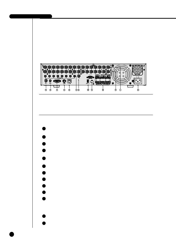
No |
Name |
Function |
|
|
|
|
|
1 |
VIDEO IN |
Composite Video Signal Input Port (BNC Style |
|
Connector) |
|||
|
|
||
|
|
|
|
2 |
THROUGH |
You may use THROUGH port to transmit a video |
|
signal to the other video equipment. |
|||
|
|
||
|
|
|
|
3 |
AUDIO IN |
Audio Signal Input Port (RCA Jack) |
|
|
|
|
|
4 |
SPOT |
SPOT Out Output Port (BNC Style Connector) |
|
|
|
|
|
|
OUT |
Composite Video Signal Output Port (BNC Style |
|
|
|
Connector) |
|
|
AUDIO OUT |
Audio Signal Output Port (RCA Jack) |
|
|
|
|
|
|
VGA |
VGA Video Signal Output Port |
|
|
|
|
|
|
S-VIDEO |
S-VIDEO Video Signal Output Port |
|
|
|
|
|
|
NETWORK |
Network Connection Port |
|
|
|
|
|
|
IEEE1394 |
IEEE1394 Type Device Connection Port |
|
|
|
|
|
|
ALARM |
- ALARM IN 1~16 : Alarm Input Port |
|
|
|
- ALARM RESET IN : Alarm Reset Port |
|
|
|
- ALARM OUT1~4 : Alarm Output Port |
|
|
|
- TX+, TX-, RX+, RX- : RS-485 Communication |
|
|
|
Port |
|
|
|
|
|
|
AC-IN |
Supports the AC110-220V(NTSC) power socket. |
|
|
|
|
|
|
USB |
A port to connect the USB type device. |
|
|
|
|
1-5


Chapter 2 Installation
2

SHR-4160N/P USER’S MANUAL
Environment Setup
DVR on the carpet or other soft material to prevent clogging of the air
To play DVR on the cabinet or rack, be sure to check the ventilation
attention to the following before you use the product. use it outdoor.
let water or liquid in the connection part or the product itself. impose excessive shock or force.
pull out the power plug unreasonably. disassemble the product on your own. exceed the rated input or output range.
power cord only.
product with an input ground with a power cord with a ground.
2-1
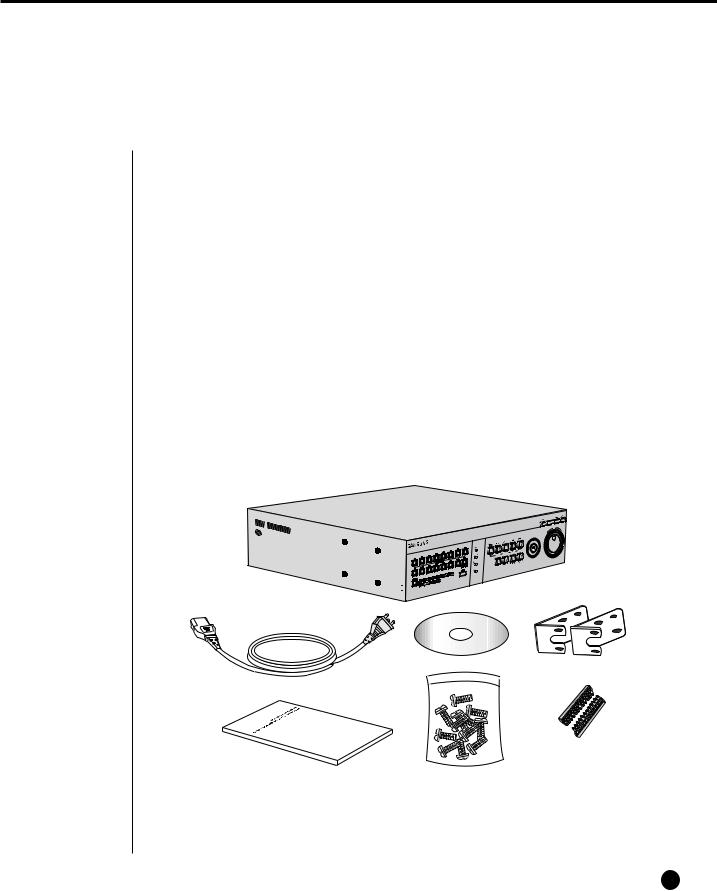
2Checking Product & Accessories
Upon delivery of a product, you shall unwrap the product and put it on the even floor or where you want to use it. Then you shall check if the following items are in it.
■Main Body
■User’s Manual
■One Power Cord
■Two Brackets
-Brackets are used to attach the product to the rack.
■Smart Viewer Software CD (Incl. PDF Manual)
■12 Screw Specials
-Please keep screw specials well to be used for HDD addition.
■2 EA of RS-485/Alarm Terminal Block
DIGITAL VIDEO |
RECODER |
SHR-4160 |
|
||
|
|
Main Body
CD |
Bracket |
Power Cord
|
|
RS-485/Alarm |
User’s Manual |
Screw |
Terminal Block |
2-2
SHR-4160N/P USER’S MANUAL
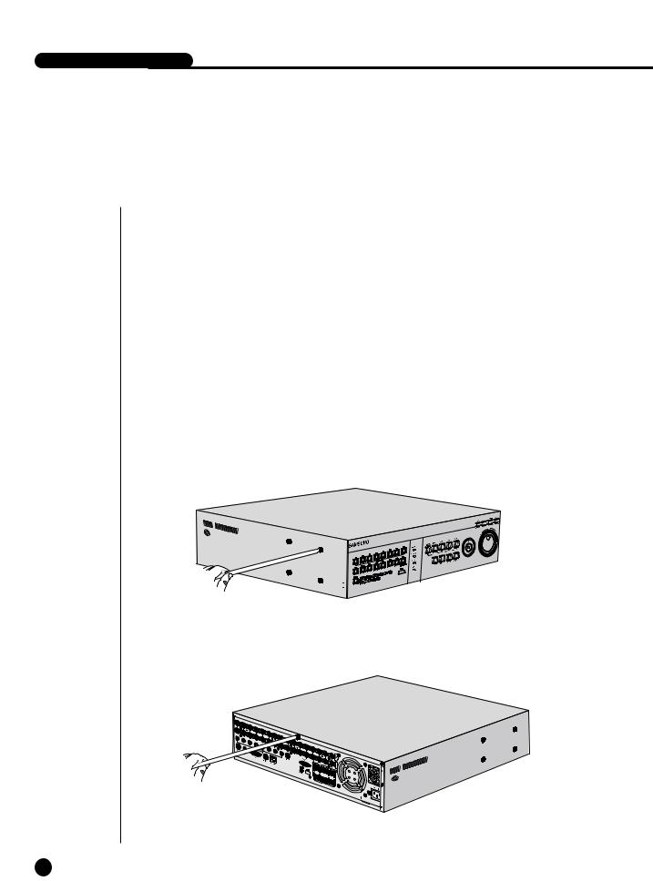
3Additional HDD Installation
You may add up to 3 more HDDs to the product.
However, since the product contains has many parts which may incur electric shock, accident, or product breakdown and improper installation or setup may disturb HDD recognition or normal product operation, you shall consult with an expert of the agency where you bought the product.
[Caution for HDD Addition]
■Do not let the cable stuck improperly nor uncoated. (This may cause breakdown or fire.)
■Be careful not to cut yourself by sharp edges of the product.
■Be careful not to miss the disassembled screws or parts. Imperfect assembly due to short of screws or parts may cause breakdown or malfunctioning.
[HDD Addition Procedure]
1. Loosen screws on both sides(5 points) and back(1 point) to detach the product cover.
DIGITAL VIDEO |
RECODER |
SHR-4160 |
|
||
|
|
2-3
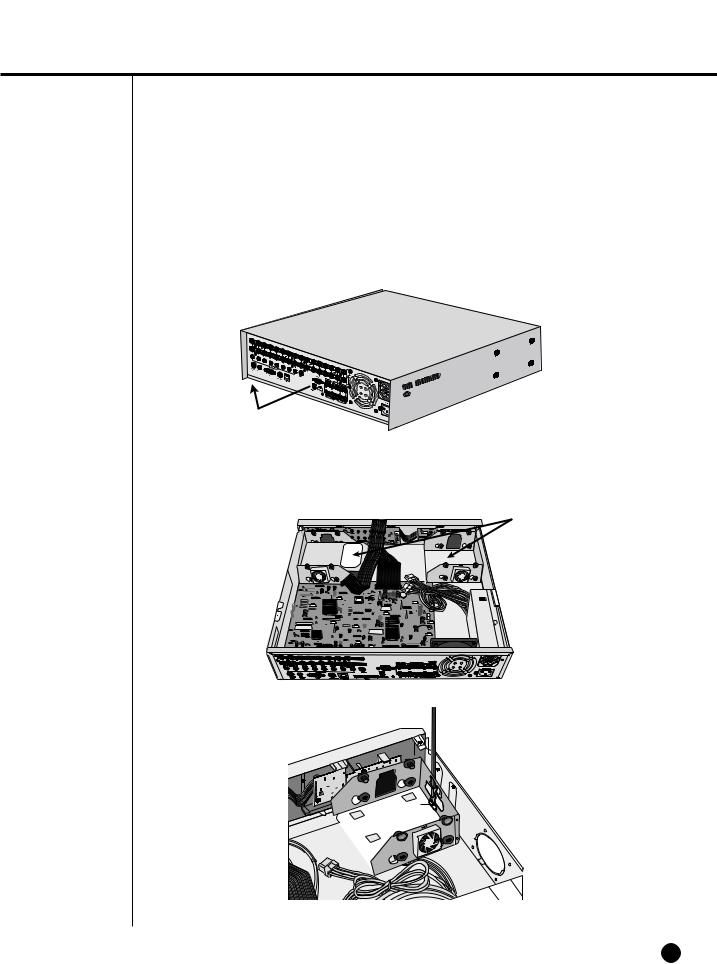
2.Detach the cover from the product. (Pull out the cover slightly and lift from the back side to detach.)
3.A bracket is fixed to each side of HDD. Please loosen the screw of the bracket to which you want to fix HDD.
BRACKET-HDD
2-4
-4160N/P USER’S MANUAL
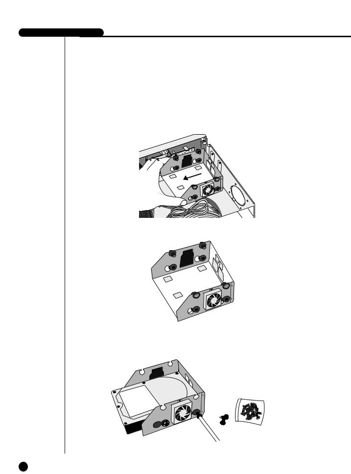
4.Pull BRACKET-HDD to the product center to detach the fixed part at the bottom to detach BRACKET-HDD from the product.
5.Tighten 4 SCREW-SPECIALs(BWH,6-32UNC,L10.5), supplied as an accessory to fix HDD to BRACKET-HDD. (Screw tighten force shall be strong enough to resist vibration.)
2-5
6.Restore HDD installed BRACKET-HDD.
(Assembly shall be done in the reverse procedure of disassembly as follows. Align the 5 fixing points at the bottom with the BRACKET-HDD fixing holes respectively and push BRACKET-HDD out of the product to align the screw fixing holes. Then, tighten the screws firmly.)
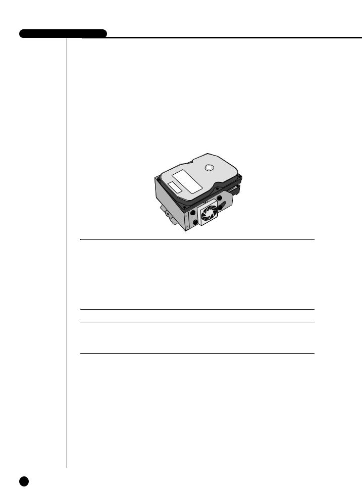
7.Check if BRACKET-HDD has been fixed to the product and connect both the power supply cable and the signal transmission cable (IDE CABLE) to the HDD.
|
|
|
|
|
|
|
|
|
|
|
|
|
|
|
|
|
|
|
|
|
|
|
|
|
|
|
|
|
|
|
|
|
|
|
|
|
|
|
|
|
|
|
|
|
|
|
|
|
|
|
|
|
|
Signal |
Transmission |
|
Power Supply |
Cable |
||||
Cable (IDE Cable) |
|
|
|
|
|
|||
|
|
|
|
|
|
|
|
|
|
|
|
|
|
|
|
|
|
2-6
-4160N/P USER’S MANUAL
8.Check the connector, wiring, and cable fixing condition inside the product and close the cover.
9.Tighten cover-fixing screws. (5 points on both sides and 1 point in the back side)You can apply 2 HDDs to each BRACKET-HDD as shown in the figure.
 Attention
For HDD addition, please select the same HDD with the existing HDD fixed to the product as far as possible. This product can accept 4 more HDDs, 2 at Primary Slot and 2 at Secondary Slot respectively. Both HDDs attached to Primary Slot and Secondary Slot shall be set to Master and Slave respectively. Refer to User’s Manual for Master or Slave Jumper Setting.
In the event of only one HDD installation, it shall be inserted into the Primary slot.
Note
Refer to Appendix 2 to see which HDD specifications are supplied.
2-7
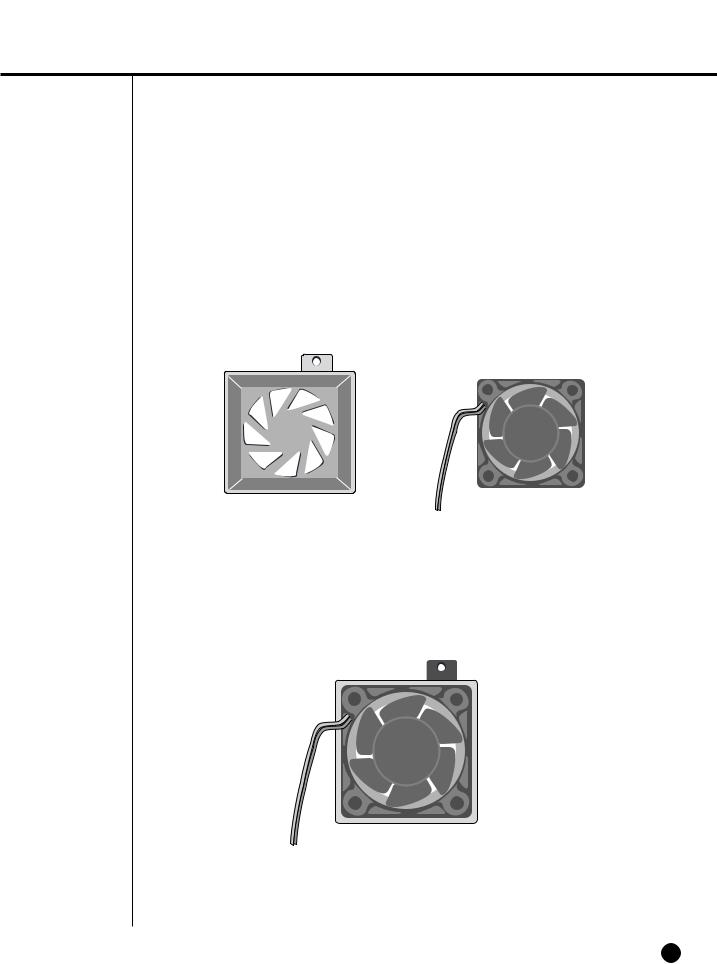
Attention
!Regarding the sub fan, you need additional brackets and sub fans as follows. The sub fan is shaped like this when viewed from the front and back. Please pay attention to the fan direction to let wind go through the fan.
@ Fix the fan as follows.
2-8
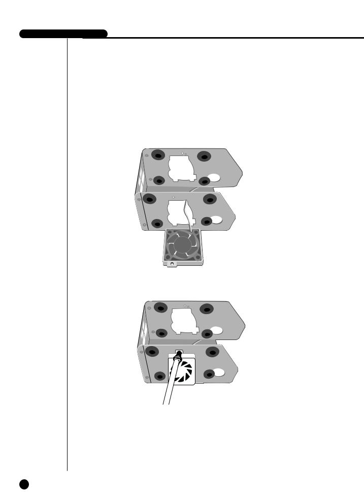
-4160N/P USER’S MANUAL
# Please install the fan to be seen from the front view of the set.
2-9
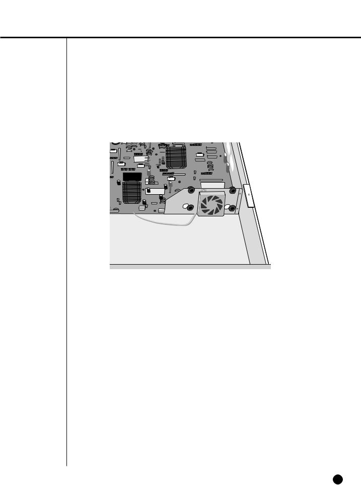
$ Fixing the fan to the left.
2-10

Chapter 3 Connecting with Other Equipment
3
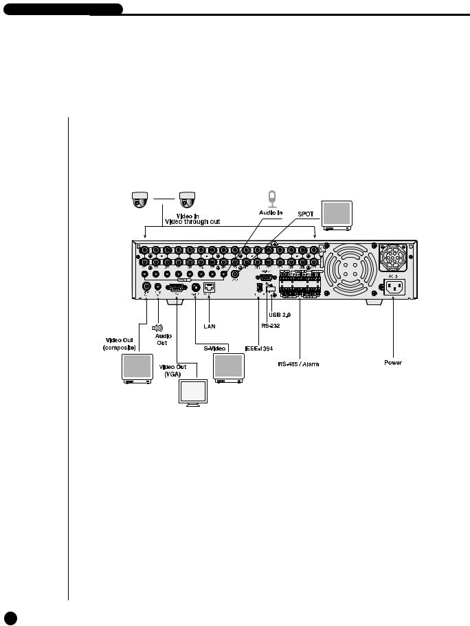
SHR-4160N/P USER’S MANUAL
Video, Audio, & Monitor

2Connecting Network
● Connecting to Internet through Ethernet(10/100BaseT)
● Connecting Internet through ADSL
3-2

-4160N/P USER’S MANUAL
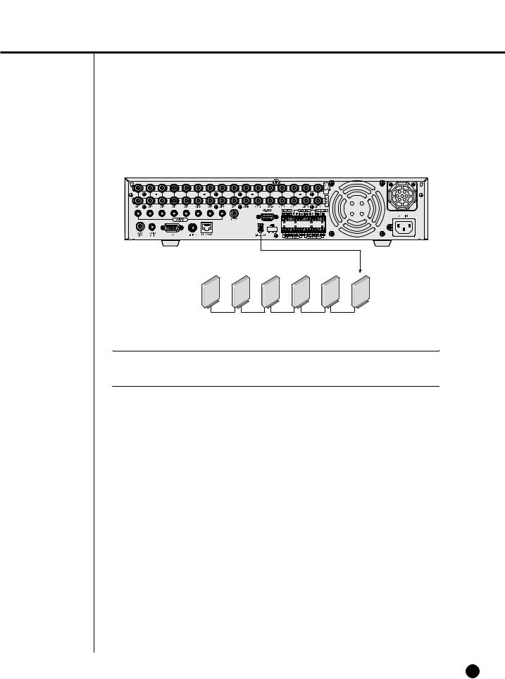
IEEE1394 Device
the IEEE1394 hard disk through the back port of SHR-4160N/P. connect up to 6 IEEE1394 armored hard disks by the Daisy-Chain
.
Menu - System - HDD Setup is necessary for recognition and
use.
 Caution
The IEEE1394 Device hard disk shall be set to Master.
as HOT PLUG to connect or disconnect the IEEE1394 device while the sysrunning.
press Connect/Disconnect in Menu - System - HDD Setup, HOT PLUG will or deleted.
Note
See 5-8 System (HDD Setup) of User’s Manual.
 Caution
-Wait until the HOT PLUG connected hard disk is stabilized enough (approx. 2 seconds per each hard disk) and click CONNECT in SHR-4160N/P MENU before use.
-Be sure to click DISCONNECT in SHR-4160N/P MENU to delete IEEE1394 Device safely. Failure of clicking DISCONNECT may cause improper operation of IEEE1394 Device.
3-3
Note
Refer to Appendix 2 to see which HDD specifications are supplied.
3-4
 Loading...