


UMTS TELEPHONE
SGH-Z630
UMTS TELEPHONE |
CONTENTS |
1. |
Safety Precautions |
2. |
Specification |
3. |
Product Function |
4. |
Array course control |
5. |
Exploded View and Parts list |
6. |
MAIN Electrical Parts List |
7. |
Block Diagrams |
8. |
PCB Diagrams |
9. |
Flow Chart of Troubleshooting |
10. Reference data |
|

Contents
1. Safety Precautions
1-1. |
Repair Precaution ...................................................................................................... |
1-1 |
|
1-2. |
ESD(Electrostatically Sensitive Devices) Precaution ............................................... |
1-2 |
|
2. Specification |
|
||
2-1. |
GSM |
General Specification ....................................................................................... |
2-1 |
2-2. |
GSM |
TX power Level ............................................................................................... |
2-2 |
3.Product Function
4.Array course control
4-1. Downloading Binary Files ...................................................................................... |
4-2 |
|
4-2. Pre-requsite for Downloading ................................................................................ |
4-2 |
|
4-3. S/W Downloader Program ..................................................................................... |
4-3 |
|
5. Exploded View and Parts list |
|
|
5-1. |
Cellular phone Exploded View .............................................................................. |
5-1 |
5-2. |
Cellular phone Parts list ........................................................................................ |
5-2 |
5-3. |
Disassembly ............................................................................................................ |
5-4 |
5-4. |
Assembly ................................................................................................................. |
5-6 |
6.MAIN Electrical Parts List
7.Block Diagrams
8.PCB Diagrams

Contents |
|
|
|
|
|
9. Flow Chart of Troubleshooting |
|
|
9-1. Baseband ............................................................................................................ |
9-1 |
|
9-1-1. Power ON ..................................................................................................... |
9-1 |
|
9-1-2. Initial ............................................................................................................. |
9-4 |
|
9-1-3. SIM Part ......................................................................................................... |
9-6 |
|
9-1-4. Microphone Part ........................................................................................... |
9-7 |
|
9-1-5. Speaker Part_1(MP3, SPEAKER PHONE) ................................................ |
9-8 |
|
9-1-6. Speaker Part_2(RECEIVER) ..................................................................... |
9-10 |
|
9-1-7. Charging Part ............................................................................................. |
9-11 |
|
9-2. RF ...................................................................................................................... |
9-13 |
|
9-2-1. EGSM RX ................................................................................................... |
9-13 |
|
9-2-2. DCS RX ...................................................................................................... |
9-15 |
|
9-2-3. PCS RX ...................................................................................................... |
9-16 |
|
9-2-4. EGSM TX ................................................................................................... |
9-17 |
|
9-2-5. DCS TX ...................................................................................................... |
9-18 |
|
9-2-6. PCS TX ...................................................................................................... |
9-19 |
|
10. Reference data

1. Safety Precautions
1-1. Repair Precaution
●Repair in Shield Box, during detailed tuning.
Take specially care of tuning or test, because specipicty of cellular phone is sensitive for surrounding interference(RF noise).
●Be careful to use a kind of magnetic object or tool,
because performance of parts is damaged by the influence of manetic force.
●Surely use a standard screwdriver when you disassemble this product, otherwise screw will be worn away.
●Use a thicken twisted wire when you measure level.
A thicken twisted wire has low resistance, therefore error of measurement is few.
●Repair after separate Test Pack and Set because for short danger (for example an overcurrent and furious flames of parts etc) when you repair board in condition of connecting Test Pack and tuning on.
●Take specially care of soldering, because Land of PCB is small and weak in heat.
●Surely tune on/off while using AC power plug, because a repair of battery charger is dangerous when tuning ON/OFF PBA and Connector after disassembing charger.
●Don't use as you pleases after change other material than replacement registered on SEC System. Otherwise engineer in charge isn't charged with problem that you don't keep this rules.
1-1
SAMSUNG Proprietary-Contents may change without notice
This Document can not be used without Samsung's authorization

Safety Precautions
1-2. ESD(Electrostatically Sensitive Devices) Precaution
Several semiconductor may be damaged easilly by static electricity. Such parts are called by ESD (Electrostatically Sensitive Devices), for example IC,BGA chip etc. Read Precaution below.
You can prevent from ESD damage by static electricity.
●Remove static electricity remained your body before you touch semiconductor or parts with semiconductor. There are ways that you touch an earthed place or wear static electricity prevention string on wrist.
●Use earthed soldering steel when you connect or disconnect ESD.
●Use soldering removing tool to break static electricity. , otherwise ESD will be damaged by static electricity.
●Don't unpack until you set up ESD on product. Because most of ESD are packed by box and aluminum plate to have conductive power,they are prevented from static electricity.
●You must maintain electric contact between ESD and place due to be set up until ESD is connected completely to the proper place or a circuit board.
1-2
SAMSUNG Proprietary-Contents may change without notice
This Document can not be used without Samsung's authorization

2. Specification
2-1. GSM/WCDMA General Specification
|
EGSM 900 |
DCS1800 |
PCS1900 |
WCDMA |
|
|
Phase 2 |
Phase 1 |
|||
|
|
|
|||
|
|
|
|
|
|
Freq. Band[MHz] |
880~915 |
1710~1785 |
1850~1910 |
1920~1980 |
|
Uplink/Downlink |
925~960 |
1805~1880 |
1930~1990 |
2110~2170 |
|
|
|
|
|
|
|
ARFCN range |
0~124 & |
512~885 |
512~810 |
10562~10838 |
|
975~1023 |
|||||
|
|
|
|
||
|
|
|
|
|
|
Tx/Rx spacing |
45 MHz |
95 MHz |
80 MHz |
190 MHz |
|
|
|
|
|
|
|
Mod. Bit rate/ |
270.833 kbps |
270.833 kbps |
270.833 kbps |
3.84 Mcps/s |
|
Bit Period |
3.692 us |
3.692 us |
3.692 us |
||
|
|||||
|
|
|
|
|
|
Time Slot |
576.9 us |
576.9 us |
576.9 us |
|
|
Period/Frame |
10 ms |
||||
4.615 ms |
4.615 ms |
4.615 ms |
|||
Period |
|
||||
|
|
|
|
||
|
|
|
|
|
|
Modulation |
0.3 GMSK |
0.3 GMSK |
0.3 GMSK |
UL:2BPSk |
|
DL:QPSK |
|||||
|
|
|
|
||
|
|
|
|
|
|
MS Power |
33 dBm~5 dBm |
30 dBm~0 dBm |
30 dBm~0 dBm |
MAX:24(+1,-3) dBm |
|
MIN:<-50 dBm |
|||||
|
|
|
|
||
|
|
|
|
|
|
Power Class |
5 pcl ~ 19 pcl |
0 pcl ~ 15 pcl |
0 pcl ~ 15 pcl |
CLASS3 |
|
|
|
|
|
|
|
Sensitivity |
-102 dBm |
-100 dBm |
-100 dBm |
-106.7 dBm |
|
|
|
|
|
|
|
TDMA Mux |
8 |
8 |
8 |
- |
|
|
|
|
|
|
|
Cell Radius |
35 Km |
2 Km |
- |
- |
|
|
|
|
|
|
2-1
SAMSUNG Proprietary-Contents may change without notice
This Document can not be used without Samsung's authorization

Specification
2-2. GSM TX power class
TX Power |
EGSM900 |
|
TX Power |
|
DCS1800 |
|
TX Power |
PCS1900 |
control level |
|
control level |
|
|
control level |
|||
|
|
|
|
|
|
|||
5 |
33±2 dBm |
|
0 |
|
30±3 dBm |
|
0 |
30±3 dBm |
|
|
|
|
|
|
|
|
|
6 |
31±2 dBm |
|
1 |
|
28±3 dBm |
|
1 |
28±3 dBm |
|
|
|
|
|
|
|
|
|
7 |
29±2 dBm |
|
2 |
|
26±3 dBm |
|
2 |
26±3 dBm |
|
|
|
|
|
|
|
|
|
8 |
27±2 dBm |
|
3 |
|
24±3 dBm |
|
3 |
24±3 dBm |
|
|
|
|
|
|
|
|
|
9 |
25±2 dBm |
|
4 |
|
22±3 dBm |
|
4 |
22±3 dBm |
|
|
|
|
|
|
|
|
|
10 |
23±2 dBm |
|
5 |
|
20±3 dBm |
|
5 |
20±3 dBm |
|
|
|
|
|
|
|
|
|
11 |
21±2 dBm |
|
6 |
|
18±3 dBm |
|
6 |
18±3 dBm |
|
|
|
|
|
|
|
|
|
12 |
19±2 dBm |
|
7 |
|
16±3 dBm |
|
7 |
16±3 dBm |
|
|
|
|
|
|
|
|
|
13 |
17±2 dBm |
|
8 |
|
14±3 dBm |
|
8 |
14±3 dBm |
|
|
|
|
|
|
|
|
|
14 |
15±2 dBm |
|
|
|
|
|
|
|
|
9 |
|
12±4 dBm |
|
9 |
12±4 dBm |
||
|
|
|
|
|
|
|
|
|
15 |
13±2 dBm |
|
10 |
|
10±4 dBm |
|
10 |
10±4 dBm |
|
|
|
|
|
|
|
|
|
16 |
11±3 dBm |
|
11 |
|
8±4 dBm |
|
11 |
8±4 dBm |
|
|
|
|
|
|
|
|
|
17 |
9± 3dBm |
|
12 |
|
6±4 dBm |
|
12 |
6±4 dBm |
|
|
|
|
|
|
|
|
|
18 |
7±3 dBm |
|
13 |
|
4±4 dBm |
|
13 |
4±4 dBm |
|
|
|
|
|
|
|
|
|
19 |
5±3 dBm |
|
14 |
|
2±5 dBm |
|
14 |
2±5 dBm |
|
|
|
|
|
|
|
|
|
|
|
|
15 |
|
0±5 dBm |
|
15 |
0±5 dBm |
|
|
|
|
|
|
|
|
|
|
|
2-2 |
|
|
|
|
||
|
|
|
|
|
|
|
|
|
|
SAMSUNG Proprietary-Contents may change without notice |
|
||||||
This Document can not be used without Samsung's authorization

3. Product Function
3-1. Main Function
-Camera and camcorder -Image editor
-Music player -File viewer -Bluetooth -Photo printing -i-mode browser
-Get personal with photo/vIDEO caller ID -Name card
-Multimedia Message Service (i-MMS) -Email (i-mail)
-Java
-Voice recorder
3-1
SAMSUNG Proprietary-Contents may change without notice
This Document can not be used without Samsung's authorization
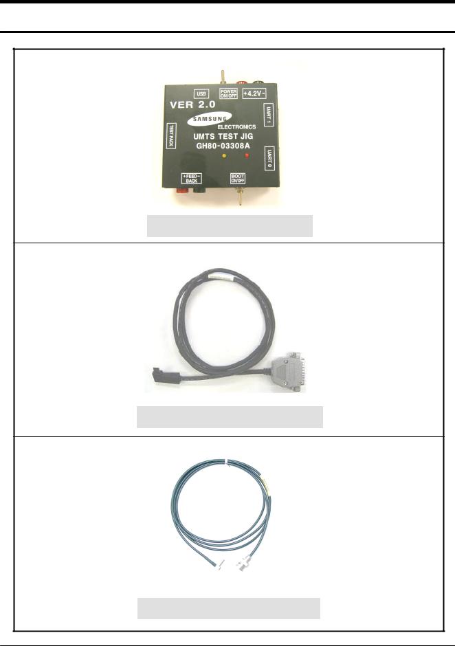
4. Array course control
Test JIG (GH80-03308A)
IF Test Cable (GH39-00478A)
RF Test Cable (GH39-00397A)
4-1
SAMSUNG Proprietary-Contents may change without notice
This Document can not be used without Samsung's authorization
Array course control
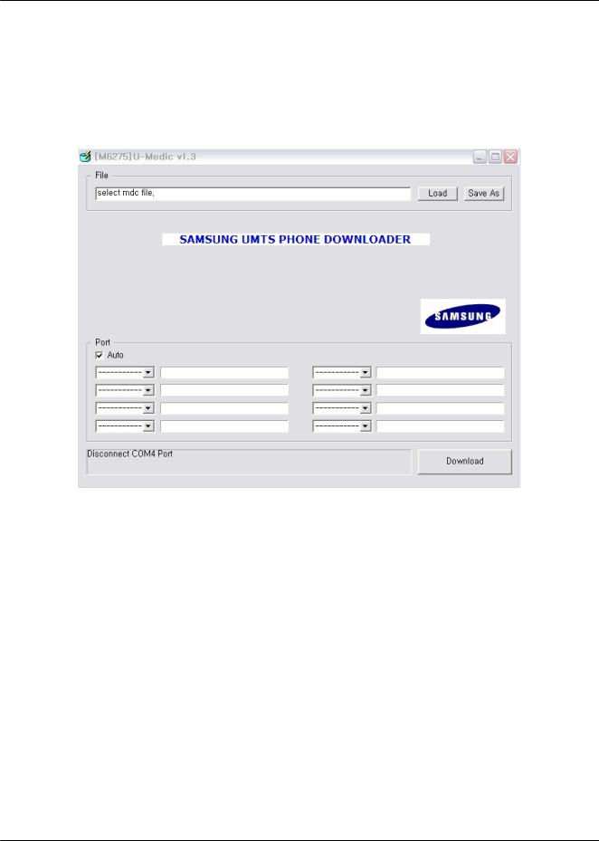
4.1 Downloading Binaries.
Start the Downloader application.
You can get the downloader program from binary zip file. Unzip the file and move to the \tools\downloa der directory. You will see below if run the [M6275]U-Medic v1.3_SVC.exe file.
Please follow the order. The detailed fact is explained below. (store the user data using PC-Studio3 if ne cessary)
1.Load the Z630.mdc file.
2.Connect the Mobile Handset to the PC via USB port.
3.Download.
First, click the 'Load' button to select “Z630.mdc” file. The mdc file is located in the \tools\downloader dir ectory. And then Connect the Mobile Handset to the PC via USB port. Press power button with red color and button captioned 4 to put the mobile into download mode. To verify that the mobile is put into down load mode, just check the front LCD screen of the mobile. (USB DOWNLOAD SAMSUNG UMTS)
Once the mobile is detected/sensed by the Downloader Application, the appropriate Mobile Entry will be enabled in the application screen.Optionally Port Search button could be pressed to detect/sense the mob ile.
4-2
SAMSUNG Proprietary-Contents may change without notice
This Document can not be used without Samsung's authorization
Array course control
Press 'Download' Button to proceed. After successful completion of download, a message saying Downloa d Completed will be flashed.
Please try to download again if you will see the "ERROR : Download Fail" popup. We need to download twice when the Boot and Resource code is changed. This is for preventing a wrong operation.
Warning:-
Incorrect download of binary file may lead to incorrect operation of the mobile, or the mobile may not op erate at all.
4-3
SAMSUNG Proprietary-Contents may change without notice
This Document can not be used without Samsung's authorization

5. Exploded View and Parts List
5-1. Cellular phone Exploded View
|
|
QSP05 |
|
|
QMW01 |
|
|
QFU01 |
|
|
QCA00 |
QHI01 |
QME03 |
|
|
QKP02 |
|
|
|
|
QFR01 |
|
|
|
|
QLC01 |
|
QCK01 |
QBR03 |
QVO01 |
|
QME01 |
|
|
|
QCA01 |
|
|
QCR12 |
QMI03 |
|
|
QFL01 |
|
|
|
|
QMP01 |
QCA02 |
|
|
|
|
QPC01 |
|
|
QVK01 |
|
|
QSH01 |
|
|
QCB01 |
|
QCR17 |
|
|
|
QAN02 |
|
QCR32 |
|
|
|
|
QSD01 |
|
QRE01 |
|
|
|
QIF01 |
|
QCW01 |
QRF01 |
|
QCR56 |
|
|
QBA01 |
|
|
QBA00 |
|
|
|
5-1 |
|
SAMSUNG Proprietary-Contents may change without notice
This Document can not be used without Samsung's authorization

Exploded View and Parts List
5-2. Cellular phone Parts list
Design LOC |
Discription |
SEC CODE |
|
QAN02 |
|
INTENNA-SGHZ630 |
GH42-00911A |
QBA00 |
|
ASSY CASE-BATTERY |
GH98-02392A |
QBA01 |
|
BATTERY-880MAH,BLK,MAIN |
GH43-02253A |
QBR03 |
|
IPR-BRACKET SUB KEY V2 |
GH70-01675A |
QCA00 |
|
UNIT-VGA CAMERA(SELF) |
GH59-03204A |
QCA01 |
|
UNIT-2M CAMERA(REC) |
GH59-03190A |
QCA02 |
|
UNIT-CAMERAKEY |
GH59-03237A |
QCB01 |
|
CBF COAXIAL CABLE-SGHZ630 ANTE |
GH39-00598A |
QCK01 |
|
ASSY KEY-CAMERA |
GH98-02751A |
QCR06 |
|
SCREW-MACHINE |
6001-001155 |
QCR12 |
|
SCREW-MACHINE |
6001-001530 |
QCR17 |
|
SCREW-MACHINE |
6001-001460 |
QCR32 |
|
SCREW-MACHINE |
6001-001700 |
QCW01 |
|
PMO-COVER WINDOW CAMERA |
GH72-34702A |
QFL01 |
|
ASSY MEC-HINGE S/L F/C |
GH75-09403A |
QFR01 |
|
MEA-FRONT KIT(CL/GRY) |
GH97-06739A |
QFU01 |
|
ASSY MEC-UPPER SLIDE |
GH75-09381A |
QHI01 |
|
ASSY ACCE-PUSH ROD |
GH98-01237A |
QKP02 |
|
ASSY KEYPAD-SUB(TIM/CA) |
GH75-09400A |
QLC01 |
|
MEA-LCD MODULE KIT |
GH97-06604A |
QME01 |
|
UNIT-EL KEY PBA(NAVI) |
GH59-03233A |
QME03 |
|
UNIT-SPK_MOT FPCB |
GH59-03205A |
QMI03 |
|
PMO-MIC HOLDER |
GH72-34159A |
QMP01 |
|
PBA MAIN-SGH-Z630 |
GH92-02568A |
QMW01 |
|
ASSY MEC-COVER MAIN WINDOW |
GH75-09396A |
QPC01 |
|
MEA-SLIDE FPCB KIT |
GH97-06605A |
QRF01 |
|
MPR-TAPE RF SHEET |
GH74-27744A |
QSH01 |
|
ASSY COVER-SHIELD CAN |
GH98-02614A |
QSP05 |
|
ASSY DECO-SPK |
GH98-01405A |
QVK01 |
|
UNIT-VOLUME KEY |
GH59-03239A |
QVO01 |
|
PMO-KEY VOLUME |
GH72-35859A |
QRE01 |
|
ASSY MEC-COEVER REAR |
GH75-09397A |
|
QIF01 |
PMO-COVER EAR IF |
GH72-29654A |
|
QSD01 |
PMO-COVER MICRO SD |
GH72-29655A |
5-2
SAMSUNG Proprietary-Contents may change without notice
This Document can not be used without Samsung's authorization

Exploded View and Parts List
Discription |
|
SEC CODE |
BAG PE |
|
6902-000297 |
CBF INTERFACE-DATA LINK CABLE |
|
GH39-00444A |
ADAPTOR-SGHE690,BLK,EU,A_TYPE |
|
GH44-01361A |
S/W CD-SAMSUNG PC STUDIO 3.0,Z |
|
GH46-00327A |
UNIT-EARPHONE(BLK) |
|
GH59-02499A |
LABEL(P)-WATER SOAK |
|
GH68-02026A |
LABEL(R)-MASTER TIM |
|
GH68-11408D |
MANUAL USERS-TIM ITALIAN |
|
GH68-12568A |
LABEL(R)-MAIN(TIM) |
|
GH68-12832A |
CUSHION-CASE TA2 |
|
GH69-04602A |
BOX(P)-UNIT MAIN(TIM) |
|
GH69-04636E |
RMO-HINGE DAMPER A |
|
GH73-08414A |
MPR-TAPE LCD PCB GOLD |
|
GH74-17771A |
MPR-TAPE LCD CONN A |
|
GH74-18637A |
MPR-VINYL BOHO MAIN WINDOW |
|
GH74-26869A |
MPR-VINYL BOHO REAR UPPER |
|
GH74-26872A |
MPR-VINYL BOHO REAR CAMERA |
|
GH74-26874A |
MPR-INSU TAPE |
|
GH74-26989A |
MPR-INSU TAPE |
|
GH74-26990A |
MPR-SPONGE SLIDE FPCB NOISE |
|
GH74-26997A |
MPR-TAPE SLIDE CON SHIELD |
|
GH74-27005A |
MPR-TAPE BATT MASKING |
|
GH74-27006A |
MPR-TAPE |
|
GH74-27010A |
MPR-TAPE |
|
GH74-27010A |
MPR-GASKET TAPE |
|
GH74-27014A |
MPR-TAPE MAIN KEY FPCB SHIELD |
|
GH74-27283A |
MPR-TAPE LCD MASKING A |
|
GH74-27284A |
MPR-TAPE LCD MASKING B |
|
GH74-27285A |
MPR-TAPE LCD DONG |
|
GH74-27287A |
MPR-TAPE 2M CAMERA CON |
|
GH74-27422A |
MPR-INSU TAPE |
|
GH74-27424A |
MPR-TAPE MAIN CON |
|
GH74-27435A |
MPR-TAPE SHEET SLIDE SCREW |
|
GH74-27743A |
MPR-INSU TAPE |
|
GH74-27774A |
MPR-SPONGE REAR BGA ABS A |
|
GH74-28042A |
MPR-SPONGE REAR BGA ABS B |
|
GH74-28043A |
MPR-SPONGE T FLASH |
|
GH74-28055A |
MPR-INSU TAPE |
|
GH74-28186A |
MPR-VINYL BOHO MAIN WINDOW |
|
GH74-28397A |
MPR-TAPE MAIN WINDOW WATER |
|
GH74-28420A |
AS-IC-MCP UMTS |
|
GH81-05913A |
5-3 |
|
|
|
|
|
SAMSUNG Proprietary-Contents may change without notice |
|
|
This Document can not be used without Samsung's authorization

Exploded View and Parts List
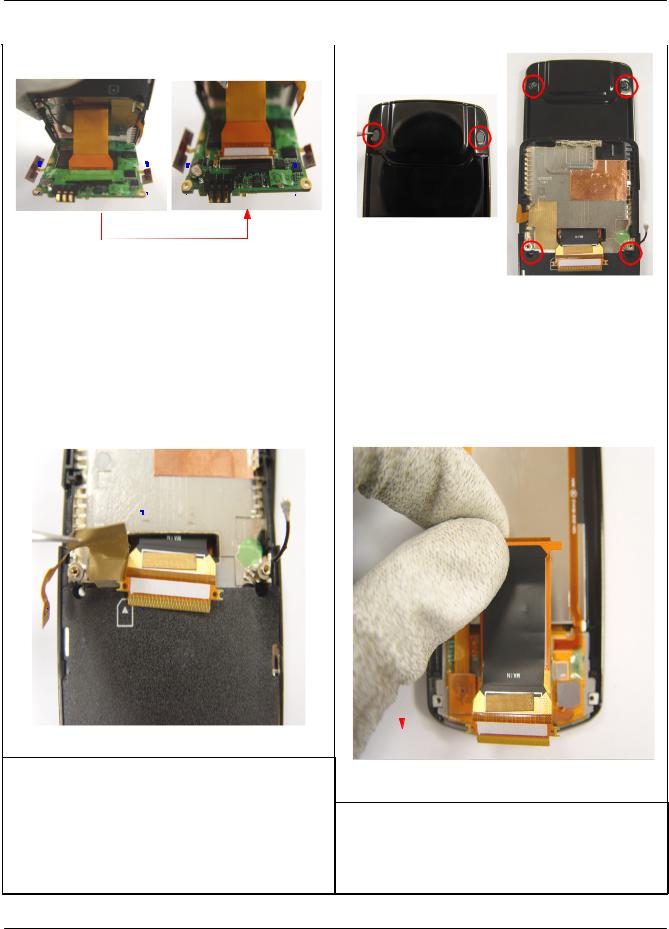
5-3. Disassembly
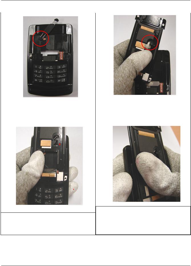
1
Unscrew 4 places of the Rear.
caution
1)Attention, Avoid scratching
2)using the star driver
2
1)Open the lower part of Rear using stick for disassembly. And With the picture it disassemble in same order (And
disassemble in order such as the picture)
caution
1) Attention, Avoid scratching
3


1)After remove the green tape, disassemble the 3*4 connector
2)After disassemble the CAM KEY FPCB using tweezers, 3*4 key FPCB is located in CAM KEY FPCB behind.
3)Disassemble VOL KEY FPCB using tweezers.
4)Disassemble INTENNA WIRE using tweezers.
5)Softly lift the CAMERA using tweezers.
caution
1)When moving the position of the 3*4 KEY CONNECTOR FPCB and CAM KEY FPCB, attention for the FPCB not to be damaged,
2)When disassembling INTENA WIRE, attention for the end of the WIRE not to be bend.
5-4
SAMSUNG Proprietary-Contents may change without notice
This Document can not be used without Samsung's authorization
Exploded View and Parts List
4 |
|
|
|
|
|
|
|
|
|
|
|
|
|
|
|
|
|
|
|
|
|
|
|
|
|
|
|
|
|
|
|
|
|
|
|
|
|
|
|
|
|
|
|
|
|
|
|
|
|
|
|
|
|
|
|
|
|
|
|
|
|
|
|
|
|
|
|
|
|
|
|
|
|
5 |
|
|
|
|
|
|
|
|
|
|
|
|
|
|
|
|
|
|
|
|
|
|
|
|
|
|
|
|
|
|
|
|
|
|
|
|
|
|
|
|
|
|
|
|
|
|
|
|
|
|
|
|
|
|
|
|
|
|
|
|
|
|
|
|
|
|
|
|
|
|
|
|
|
|
|
|
|
|
|
|
|
|
|
|
|
|
|
|
|
|
|
|
|
|
|
|
|
|
|
|
|
|
|
|
|
|
|
|
|
|
|
|
|
|
|
|
|
|
|
|
|
|
|
|
|
|
|
|
|
|
|
|
|
|
|
|
|
|
|
|
|
|
|
|
|
|
|
|
|
|
|
|
|
|
|
|
|
|
|
|
|
|
|
|
|
|
|
|
|
|
|
|
|
|
|
|
|
|
|
|
|
|
|
|
|
|
|
|
|
|
|
|
|
|
|
|
|
|
|
|
|
|
|
|
|
|
|
|
|
|
|
|
|
|
|
|
|
|
|
|
|
|
|
|
|
|
|
|
|
|
|
|
|
|
|
|
|
|
|
|
|
|
|
|
|
|
|
|
|
|
|
|
|
|
|
|
|
|
|
|
|
|
|
|
|
|
|
|
|
|
|
|
|
|
|
|
|
|
|
|
|
|
|
|
|
|
|
|
|
|
|
|
|
|
|
|
|
|
|
|
|
|
|
|
|
|
|
|
|
|
|
|
|
|
|
|
|
|
|
|
|
|
|
|
|
|
|
|
|
|
|
|
|
|
|
|
|
|
|
|
|
|
|
|
|
|
|
|
|
|
|
|
|
|
|
|
|
|
|
|
|
|
|
|
|
|
|
|
|
|
|
|
|
|
|
|
|
|
|
|
|
|
|
|
|
|
|
|
|
|
|
|
|
|
|
|
|
|
|
|
|
|
|
|
|
|
|
|
|
|
|
|
|
|
|
|
|
|
|
|
|
|
|
|
|
|
|
|
|
|
|
|
|
|
|
|
|
|
|
|
|
|
|
|
|
|
|
|
|
|
|
|
|
|
|
|
|
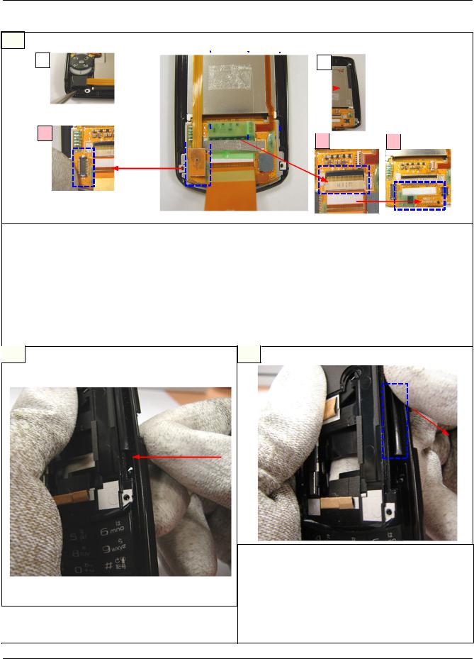
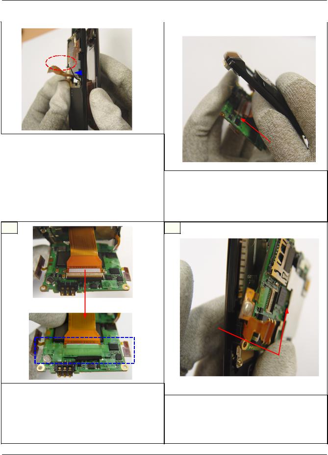
1) |
Remove a green insulation Tape on the |
|
|
|
|
|||||||||||||||||||||||||||||||||||||||||||||
|
FPCB Connector using tweezers. |
|
|
|
|
|||||||||||||||||||||||||||||||||||||||||||||
|
1) |
Remove the Screw Cap |
||||||||||||||||||||||||||||||||||||||||||||||||
2) |
Open the cover of the Connector and pull |
|||||||||||||||||||||||||||||||||||||||||||||||||
2) |
Unscrew 4 places of Front |
|||||||||||||||||||||||||||||||||||||||||||||||||
|
out the Slide FPCB carefully in the PBA. |
|||||||||||||||||||||||||||||||||||||||||||||||||
|
caution |
|||||||||||||||||||||||||||||||||||||||||||||||||
caution |
1) |
Attention, SET does not occur scratch |
||||||||||||||||||||||||||||||||||||||||||||||||
1) |
Attention not to be get the crack |
2) |
Using the a screwdriver |
|||||||||||||||||||||||||||||||||||||||||||||||
6 |
|
|
|
|
|
|
|
|
|
|
|
|
|
|
|
|
|
|
|
|
|
|
|
|
|
|
|
|
|
|
|
|
|
|
|
|
|
|
|
|
|
|
|
|
|
7 |
|
|
|
|
|
|
|
|
|
|
|
|
|
|
|
|
|
|
|
|
|
|
|
|
|
|
|
|
|
|
|
|
|
|
|
|
|
|
|
|
|
|
|
|
|
|
|
|
|
|
|
|
|
|
|
|
|
|
|
|
|
|
|
|
|
|
|
|
|
|
|
|
|
|
|
|
|
|
|
|
|
|
|
|
|
|
|
|
|
|
|
|
|
|
|
|
|
|
|
|
|
|
|
|
|
|
|
|
|
|
|
|
|
|
|
|
|
|
|
|
|
|
|
|
|
|
|
|
|
|
|
|
|
|
|
|
|
|
|
|
|
|
|
|
|
|
|
|
|
|
|
|
|
|
|
|
|
|
|
|
|
|
|
|
|
|
|
|
|
|
|
|
|
|
|
|
|
|
|
|
|
|
|
|
|
|
|
|
|
|
|
|
|
|
|
|
|
|
|
|
|
|
|
|
|
|
|
|
|
|
|
|
|
|
|
|
|
|
|
|
|
|
|
|
|
|
|
|
|
|
|
|
|
|
|
|
|
|
|
|
|
|
|
|
|
|
|
|
|
|
|
|
|
|
|
|
|
|
|
1)Softly remove tape using tweezers, FPCB and in tape internal it pulls out Extract FPCB to TAPE inside after lift TAPE using
tweezers
caution
1)When pulling out the FPCB on LCD, not to be bend.
2) Remove bronze cover tape, FPCB take off in lower such as the picture
caution
1)When pulling out the FPCB on LCD, not to be bend.
5-5
SAMSUNG Proprietary-Contents may change without notice
This Document can not be used without Samsung's authorization
Exploded View and Parts List
9
|
|
|
|
|
|
|
|
|
|
|
|
|
|
|
|
|
|
|
|
|
|
|
|
|
|
|
|
|
|
|
|
|
|
|
|
|
|
|
|
|
|
|
|
|
|
|
|
|
|
|
|
|
|
|
|
|
|
|
|
|
|
|
|
|
|
|
||
|
|
|
|
|
|
|
|
|
|
|
|
|
|
|
|
|
|
|
|
|
|
|
|
|
|
|
|
|
|
|
|
|
|
|
|
|
|
|
|
|
|
|
|
|
|
|
|
|
|
|
|
|
|
|
|
|
|
|
|
|
|
|
|
|
|
|
|
|
|
|
|
|
|
|
|
|
|
|
|
|
|
|
|
|
|
|
|
|
|
|
|
|
|
|
|
|
|
|
|
|
|
|
|
|
|
|
|
|
|
|
|
|
|
|
|
|
|
|
|
|
|
|
|
|
|
|
|
|
|
|
|
|
|
|
|
|
|
|
|
|
|
|
|
|
|
|
|
|
|
|
|
|
|
|
|
|
|
|
|
|
|
|
|
|
|
|
|
|
|
|
|
|
|
|
|
|
|
|
|
|
|
|
|
|
|
|
|
|
|
|
|
|
|
|
|
|
|
|
|
|
|
|
|
|
|
|


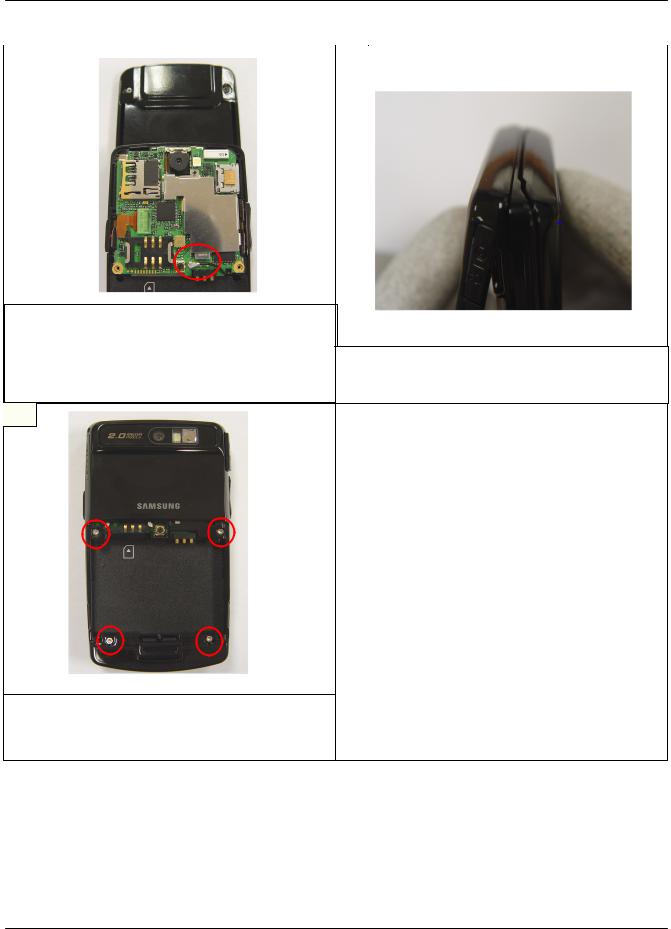
1),2) Remove VGA CAM such as pictures using tweezers, disassemble connector of the bottom
3) Remove tape in FPCB connector using tweezers
3),4) After lift connector pin, disassemble FPCB using tweezers
5) Remove SPK,MOT ASS'Y using tweezers
caution
1)When disassemble VGA CAMERA using tweezers, attention not to be get the crack
2)Attention not to be get the damage
3)When disassemble LCD FPCB, using tweezers not to be get the crack
10
1)Downing lower such as picture
caution
1) Attention, Avoid scratching.
11
1)With right hand thumb it hands down the LOWER in the lower part and the FRONT
and it disjoints.
caution
1)With the picture together it catches the portion which is to the dotted line which is a blue
2)Attention, Avoid scratching.
5-6
SAMSUNG Proprietary-Contents may change without notice
This Document can not be used without Samsung's authorization

Exploded View and Parts List
5-4. Assembly
1 |
|
2 |
|
|
|
|
|
|
|
|
|
|
|
|
|
|
|
|
|
|
|
|
|
|
|
|
|
|
|
|
|
|
|
|
|
|
|
|
|
|
|
|
|
|
|
|
|
|
|
|
|
|
|
|
|
|
|
|
|
|
|
|
|
|
|
|
|||
|
|
|
|
|
|
|
|
|
|
|
|
|
|
|
|
|
|
|
|
|
|
|
|
|
|
|
|
|
|
|||||
|
|
|
|
|
|
|
|
|
|
|
|
|
|
|
|
|
|
|
|
|
|
|
|
|
|
|
|
|
|
|||||
|
|
|
|
|
|
|
|
|
|
|
|
|
|
|
|
|
|
|
|
|
|
|
|
|
|
|
|
|
|
|
|
|
|
|
|
|
|
|
|
|
|
|
|
|
|
|
|
|
|
|
|
|
|
|
|
|
|
|
|
|
|
|
|
|
|
|
|
|
|
|
|
|
|
|
|
|
|
|
|
|
|
|
|
|
|
|
|
|
|
|
|
|
|
|
|
|
|
|
|
|
|
|
|
|
|
|
|
|
|
|
|
|
|
|
|
|
|
|
|
|
|
|
|
|
|
|
|
|
|
|
|
|
|
|
|
|
|
|
|
|
|
|
|
|
|
|
|
|
|
|
|
|
|
|
|
|
|
|
|
|
|
|
|
|
|
|
|
|
|
|
|
|
|
|
|
|
|
|
|
|
|
|
|
|
|
|
|
|
|
|
|
|
|
|
|
|
|
|
|
|
|
|
|
|
|
|
|
|
|
|
|
|
|
|
|
|
|
|
|
|
|
|
|
|
|
|
|
|
|
|
|
|
|
|
|
|
|
|
|
|
|
|
|
|
|
|
1) |
The SPK arriving safely first it arrives |
||
|
|
|
safely the MOT after. It follows the line |
||
|
|
|
which is coming to carve the FPCB in the |
||
|
|
|
LCD and it arrives safely. |
||
|
|
2) |
It inserts the FPCB in CONNECTOR portion |
||
|
|
caution |
|||
1) With the picture 3*4 key arrives |
|||||
1) |
The MOT&SPK the ASS'Y should have |
||||
safely the UPPER |
|||||
|
arrived safely completely in shooting out, it |
||||
caution |
|
||||
|
is confirmed. |
||||
1) 3*4 KEY`s hole in lower to be in contact |
|
||||
2) |
In order for the FPCB not to be the crack |
||||
in the UPPER, arrives safely. |
|
the branch, it arrives safely. |
|||
3 |
|
4 |
|
|
|
|
|
|
|
|
|
|
|
|
|
|
|
|
|
|
|
|
|
|
|
|
|
|
|
|
|
|
|
|
|
|
|
|
|
|
|
|
|
|
|
|
|
|
|
|
|
|
|
|
|
|
|
|
|
|
|
|
|
|
|
|
|
|
|
|
|
|
|
|
|
|
|
|
|
|
|
|
|
|
|
|
|
|
|
|
|
|
|
|
|
|
|
|
|
|
|
|
|
|
|
|
|
|
|
|
|
|
|
|
|
|
|
|
|
|
|
|
|
|
|
|
|
|
|
|
|
|
|
|
|
|
|
|
|
|
|
|
|
|
|
|
|
|
|
|
|
|
|
|
|
|
|
|
|
|
|
|
|
|
|
|
|
|
|
|
|
|
|
|
|
|
|
|
|
|
|
|
|
|
|
|
|
|
|
|
|
|
|
|
|
|
|
|
|
|
|
|
|
|
|
|
|
|
|
|
|
|
|
|
|
|
|
|
|
|
|
|
|
|
|
|
|
|
|
|
|
|
|
|
|
|
|
|
|
|
|
|
|
|
|
|
|
|
|
|
|
|
|
|
|
|
|
|
|
|
|
|
|
|
|
|
|
|
|
|
|
|
|
|
|
|
|
|
|
|
|
|
|
|
|
|
|
|
|
|
|
|
|
|
|
|
|
|
|
|
|
|
|
|
|
|
|
|
|
|
|
|
|
|
|
|
|
|
|
|
|
|
|
|
|
|
|
|
|
|
|
|
|
|
|
|
|
|
|
|
|
|
|
|
|
|
|
|
|
|
|
|
|
|
|
|
|
|
|
|
|
|
|
|
|
|
|
|
|
|
|
|
|
|
|
|
|
|
|
|
|
|
|
|
|
|
|
|
|
|
|
|
|
|
|
|
|
|
|
|
|
|
|
|
|
|
|
|
|
|
|
|
|
|
|
|
|
|
|
|
|
|
|
|
|
|
|
|
|
|
|
|
|
|
|
|
|
|
|
|
|
|
|
|
|
|
|
|
|
|
|
|
|
|
|
|
|
|
|
|
|
|
|
|
|
|
|
|
|
|
|
|
|
|
|
|
|
|
|
|
|
|
|
|
|
|
|
|
|
|
|
|
|
|
|
|
|
|
|
|
|
|
|
|
|
|
|
|
|
|
|
|
|
|
|
|
|
|
|
|
|
|
|
|
|
|
|
|
|
|
|
|
|
|
|
|
|
|
|
|
|
|
|
|
|
|
|
|
|
|
|
|
|
|
|
|
|
|
|
|
|
|
|
|
|
|
|
|
|
|
|
|
|
|
|
|
|
|
|
|
|
|
|
|
|
|
|
|
|
|
|
|
|
|
|
|
|
|
|
|
|
|
|
|
|
|
|
|
|
|
|
|
|
|
|
|
|
|
|
|
|
|
|
|
|
|
|
|
|
|
|
|
|
|
|
|
|
|
|
|
|
|
|
|
|
|
|
|
|
|
|
|
|
|
|
|
|
|
|
|
|
|
|
|
|
|
|
|
|
|
|
|
|
|
|
|
|
|
|
|
|
|
|
|
|
|
|
|
|
|
|
|
|
|
|
|
|
|
|
|
|
|
|
|
|
|
|
|
|
|
|
|
|
|
|
|
|
|
|
|
|
|
|
|
|
|
|
|
|
|
|
|
|
|
|
|
|
|
|
|
|
|
|
|
|
|
|
|
|
|
|
|
|
|
|
|
|
|
|
|
|
|
|
|
|
|
|
|
|
|
|
|
|
|
|
|
|
|
|
|
|
|
|
|
|
|
|
|
|
|
|
|
|
|
|
|
|
|
|
|
|
|
|
|
|
|
|
|
|
|
|
|
|
|
|
|
|
|
|
|
|
|
|
|
|
|
|
|
|
|
|
|
|
|
|
|
|
|
|
|
|
|
|
|
|
|
|
|
|
|
|
|
|
|
|
|
|
|
|
|
|
|
|
|
|
|
|
|
|
|
|
|
|
|
|
|
|
|
|
|
|
|
|
|
|
|
|
|
|
|
|
|
|
|
|
|
|
|
|
|
|
|
|
|
|
|
|
|
|
|
|
|
|
|
|
|
|
|
|
|
|
|
|
|
|
|
|
|
|
|
|
|
|
|
|
|
|
|
|
|
|
|
|
|
|
|
|
|
|
|
|
|
|
|
|
|
|
|
|
|
|
|
|
|
|
|
|
|
|
|
|
|
|
|
|
|
|
|
|
|
|
|
|
|
|
|
|
|
|
|
|
|
|
|
|
|
|
|
|
|
|
|
|
|
|
|
|
|
|
|
|
|
|
|
|
|
|
|
|
|
|
|
|
|
|
|
|
|
|
|
|
|
|
|
|
|
|
|
|
|
|
|
|
|
|
|
|
|
|
|
|
|
|
|
|
|
|
|
|
|
|
|
|
|
|
|
|
|
|
|
|
|
|
|
|
|
|
|
|
|
|
|
|
|
|
|
|
|
|
|
|
|
|
|
|
|
|
|
|
|
|
|
|
|
|
|
|
|
|
|
|
|
|
|
|
|
|
|
|
|
|
|
|
|
|
|
|
|
|
|
|
|
|
|
|
|
|
|
|
|
|
|
|
|
|
|
|
|
|
|
|
|
|
|
|
|
|
|
|
|
|
|
|
|
|
|
|
|
|
|
|
|
|
|
|
|
|
|
|
|
|
|
|
|
|
|
|
|
|
|
|
|
|
|
|
|
|
|
|
|
|
|
|
|
|
|
|
|
|
|
|
|
|
|
|
|
|
|
|
|
|
|
|
|
|
|
|
|
|
|
|
|
|
|
|
|
|
|
|
|
|
|
|
|
|
|
|
|
|
|
|
|
|
|
|
|
|
|
|
|
|
|
|
|
|
|
|
|
|
|
|
|
|
|
|
|
|
|
|
|
|
|
|
|
|
|
|
|
|
|
|
|
|
|
|
|
|
|
|
|
|
|
|
|
|
|
|
|
|
|
|
|
|
|
|
|
|
|
|
|
|
|
|
|
|
|
|
|
|
|
|
|
|
|
|
|
|
|
|
|
|
|
|
|
|
|
|
|
|
|
|
|
|
|
|
|
|
|
|
|
|
|
|
|
|
|
|
|
|
|
|
|
|
|
|
|
|
|
|
|
|
|
|
|
|
|
|
|
|
|
|
|
|
|
|
|
|
|
|
|
|
|
|
|
|
|
|
|
|
|
|
|
|
|
|
|
|
|
|
|
|
|
|
|
|
|
|
|
|
|
|
|
1) |
Line in the lower part in standard, it raises |
|
|||||||||||||||||
|
1) |
VGA CAMERA arrives like picture |
|
|
|||||||||||||||||||||||||||||||||||||||||||||||||||||||
|
|
|
the FPCB |
|
|||||||||||||||||||||||||||||||||||||||||||||||||||||||
|
|
|
|
|
|
|
|
|
|
|
|
|
|
|
|
|
|
|
|
|
|
|
|
|
|
|
|
|
|
|
|
|
|
|
|
|
|
|
|
|
|
||||||||||||||||||
|
2) |
LCD FPCB insult connector |
|
2) |
With the picture Bronze cover TAPE |
|
|||||||||||||||||||||||||||||||||||||||||||||||||||||
|
caution |
|
|
attatches onthe black line that is standard |
|
||||||||||||||||||||||||||||||||||||||||||||||||||||||
|
1) |
Attention, SET does not occur scratch |
|
caution |
|
||||||||||||||||||||||||||||||||||||||||||||||||||||||
|
2) |
Attention LCD FPCB not to be get the |
|
|
|||||||||||||||||||||||||||||||||||||||||||||||||||||||
|
|
1) |
Attention LCD FPCB not to be get the |
|
|||||||||||||||||||||||||||||||||||||||||||||||||||||||
|
|
crack |
|
|
crack |
|
|||||||||||||||||||||||||||||||||||||||||||||||||||||
|
|
|
|
|
|
|
|
|
|
|
|
|
|
|
|
|
|
|
|
|
|
|
|
|
|
|
|
|
|
|
|
|
|
|
|
|
|
|
5-7 |
|
|
|
|
|
|
|
|
|
|
|
|
|
|
|
|
|
|
|
|
|
|
|
|
|
|
|
|
|
|
|
|
|
|
|
|
|
|
|
|
|
|
|
|
|
|
|
|
|
|
|
|
|
|
|
|
|
|
|
|
|
|
|
|
|
|
|
|
|
|
|
|
|
|
|
|
|
|
||
|
|
|
|
|
|
|
|
|
|
|
|
|
|
|
|
|
|
|
|
|
|
|
|
|
|
|
|
|
|
|
|
|
|
|
|
|
SAMSUNG Proprietary-Contents may change without notice |
|
|||||||||||||||||||||
This Document can not be used without Samsung's authorization
Exploded View and Parts List
5 |
|
6 |
|
|
|
|
|
|
|
|
|
|
|
|
|
|
|
|
|
|
|
|
|
1) |
With the picture the LOWER inserts in |
||
1) |
The PUSH LOADER with the picture it |
||||||||||||||||||||||
|
PUSH LOADER. |
||||||||||||||||||||||
|
arrives safely to the FRONT. |
|
|||||||||||||||||||||
caution |
caution |
||||||||||||||||||||||
1) |
Attention, SET does not occur scratch |
1) |
Attention, SET does not occur scratch |
||||||||||||||||||||
7 |
|
|
|
|
|
|
|
|
|
|
|
|
|
|
|
|
|
|
|
8 |
|
|
|
|
|
|
|
|
|
|
|
|
|
|
|
|
|
|
|
|
|
|
|
|
|
|
|
|
|
|
|
|
|
|
|
|
|
|
|
|
|
|
|
|
|
|
|
|
|
|
|
|
|
|
|
|
|
|
|
|
|
|
|
|
|
|
|
|
|
|
|
|
|
|
|
|
|
|
|
|
|
|
|
|
|
|
|
|
|
|
|
|
|
|
|
|
|
|
|
|
|
|
|
|
|
|
|
|
|
|
|
|
|
|
|
|
|
|
|
|
|
|
|
|
|
|
|
|
|
|
|
|
|
|
|
|
|
|
|
|
|
|
|
|
|
|
|
|
|
|
|
|
|
|
|
|
|
|
|
|
|
|
|
|
|
|
|
|
|
|
|
|
|
|
|
|
|
|
|
|
|
|
|
|
|
|
|
|
|
|
|
|
|
|
|
|
|
|
|
|
|
|
|
|
|
|
|
|
|
|
|
|
|
|
|
|
|
|
|
|
|
|
|
|
|
|
|
|
|
|
|
|
|
|
|
|
|
|
|
|
|
|
|
|
|
|
|
|
|
|
|
|
|
|
|
|
|
|
|
|
|
|
|
|
|
|
|
|
|
|
|
|
|
|
|
|
|
|
|
|
|
|
|
|
|
|
|
|
|
|
|
|
|
|
|
|
|
|
|
|
|
|
|
|
|
|
|
|
|
|
|
|
|
|
|
|
|
|
|
|
|
|
|
|
|
|
|
|
|
|
|
|
|
|
|
|
|
|
|
|
|
|
|
|
|
|
|
|
|
|
|
|
|
|
|
|
|
|
|
|
|
|
|
|
|
|
|
|
|
|
|
|
|
|
|
|
|
|
|
|
|
|
|
|
|
|
|
|
|
|
|
|
|
|
|
|
|
|
|
|
|
|
|
|
|
|
|
|
|
|
|
|
|
|
|
|
|
|
|
|
|
|
|
|
|
|
|
|
|
|
|
|
|
|
|
|
|
|
|
|
|
|
|
|
|
|
|
|
|
|
|
|
|
|
|
|
|
|
|
1) With the picture together right side insult in FRONT shooting out.
caution
1) Attention, SET does not occur scratch
1)With the picture it hands down the FRONT left side side together by the left hand and
it inserts the LOWER.
caution
1) Attention, SET does not occur scratch
5-8
SAMSUNG Proprietary-Contents may change without notice
This Document can not be used without Samsung's authorization
Exploded View and Parts List
9 |
|
|
|
10 |
|
|
|
|
|
|
|
1)It combines the UPPER ASS'Y which in the LOWER it assembles rom before. (Combination hour you must put out the TAPE which is sticking in 3*4KEY FPCB
and it must combine and LCD FPCB enters 1) With the picture it catches the FPCB of the well).
caution
1) Attention FPCB not to be get the crack
It combines the UPPER ASS'Y which in the LOWER it assembles from before
11
1) The FPCB CONNECTOR closes and green insulation TAPE with the picture it attaches in same location.
caution
1) The green insulation TAPE attaches rightly in top part of the PORON.
5-9
SAMSUNG Proprietary-Contents may change without notice
This Document can not be used without Samsung's authorization
Exploded View and Parts List
13 |
|
14 |
|
1) Confirm whether have attached GOLD GASKET |
1)Confirm SHIELD CAN whether GOLD GASKET |
|||||||||||||||||||||||||||||||||||||||||||||||||||||||||||||||||||
TAPE with picture on SHIELD CAN HOOK |
TAPE, gray challenge TAPE with picture has |
|||||||||||||||||||||||||||||||||||||||||||||||||||||||||||||||||||
wealth side. |
attached over. |
|||||||||||||||||||||||||||||||||||||||||||||||||||||||||||||||||||
caution |
caution |
|||||||||||||||||||||||||||||||||||||||||||||||||||||||||||||||||||
1)Confirmation work |
1)Confirmation work |
|||||||||||||||||||||||||||||||||||||||||||||||||||||||||||||||||||
15 |
|
|
|
16 |
|
|
|
|
|
|
|
|
|
|
|
|
|
|
|
|
|
|
|
|
|
|
|
|
|
|
|
|
|
|
|
|
|
|
|
|
|
|
|
|
|
|
|
|
|
|
|
|
|
|
|
|
|
|
|
|
|
|
|
|
|
|
|
|
|
|
|
|
|
|
|
|
|
||||||||||||||||||||||||||||||||||||||||||||||||||||||||||||
|
|
|
|
|
|
|
|
|
|
|
|
|
|
|
|
|
|
|
|
|
|
|
|
|
|
|
|
|
|
|
|
|
|
|
|
|
|
|
|
|
|
|
|
|
|
|
|
|
|
|
|
|
|
|
|
|
|
|
|
|
|
|
|
|
|
|
|
|
|
|
|
|
|
|
|
|
|
|
|
|
|
|
|
|
|
|
|
|
|
|
|
|
|
|
|
|
|
|
|
|
|
|
|
|
|
|
|
|
|
|
|
|
|
|
|
|
|
|
|
|
|
|
|
|
|
|
|
|
|
|
|
|
|
|
|
|
|
|
|
|
|
|
|
|
|
|
|
|
|
|
|
|
|
|
|
|
|
|
|
|
|
|
|
|
|
|
|
|
|
|
|
|
|
|
|
|
|
|
|
|
|
|
|
|
|
|
|
|
|
|
|
|
|
|
|
|
|
|
|
|
|
|
|
|
|
|
|
|
|
|
|
|
|
|
|
|
|
|
|
|
|
|
|
|
|
|
|
|
|
|
|
|
|
|
|
|
|
|
|
|
|
|
|
|
|
|
|
|
|
|
|
|
|
|
|
|
|
|
|
|
|
|
|
|
|
|
|
|
|
|
|
|
|
|
|
|
|
|
|
|
|
|
|
|
|
|
|
|
|
|
|
|
|
|
|
|
|
|
|
|
|
|
|
|
|
|
|
|
|
|
|
|
|
|
|
|
|
|
|
|
|
|
|
|
|
|
|
|
|
|
|
|
|
|
|
|
|
|
|
|
|
|
|
|
|
|
|
|
|
|
|
|
|
|
|
|
|
|
|
|
|
|
|
|
|
|
|
|
|
|
|
|
|
|
|
|
|
|
|
|
|
|
|
|
|
|
|
|
|
|
|
|
|
|
|
|
|
|
|
|
|
|
|
|
|
|
|
|
|
|
|
|
|
|
|
|
|
|
|
|
|
|
|
|
|
|
|
|
|
|
|
|
|
|
|
|
|
|
|
|
|
|
|
|
|
|
|
|
|
|
|
|
|
|
|
|
|
|
1) |
After arriving safely the right lower part |
|
|
|
|
|
|
|
|
|
|
|
|
|
|
|
|
|
|
|
|
|
|
|
|
|
|
|
|
|
|
|
|
|
|
|
|
|
|
|
|
|
|
|
|
|
|
|
|
|
|
|
|
|
|
|
|
|
|
|
|
|
|
|
1) |
The CAM KEY arrives safely |
|||||||||||||||||||||||||||||||||||||||||||||||||||||||||||||||
|
first, board upper direction some it bends |
|||||||||||||||||||||||||||||||||||||||||||||||||||||||||||||||
|
2) |
The VOL KEY arrives safely |
||||||||||||||||||||||||||||||||||||||||||||||||||||||||||||||
|
with the right and it arrives safely with the |
|||||||||||||||||||||||||||||||||||||||||||||||||||||||||||||||
|
caution |
|||||||||||||||||||||||||||||||||||||||||||||||||||||||||||||||
|
left side |
1) |
The CAM, VOL KEY arrives safely. in order |
|||||||||||||||||||||||||||||||||||||||||||||||||||||||||||||
caution |
||||||||||||||||||||||||||||||||||||||||||||||||||||||||||||||||
1) |
The PBA arrives safely from the condition |
|
for the to be only caught the FRONT |
|||||||||||||||||||||||||||||||||||||||||||||||||||||||||||||
|
which slide is ascending. |
|
upper |
|||||||||||||||||||||||||||||||||||||||||||||||||||||||||||||
5-10
SAMSUNG Proprietary-Contents may change without notice
This Document can not be used without Samsung's authorization
Exploded View and Parts List
17 |
|
18 |
|
|
|
|
|
|
|
|
|
|
|
|
|
|
|
|
|
|
|
|
|
|
|
|
|
|
|
|
|
|
|
|
|
|
|
|
|
|
|
|
|
|
|
|
|
|
|
|
|
|
|
|
|
|
|
|
|
|
|
|
|
|
|
|
|
|
|
|
|
|
|
|
|
|
|
|
|
|
|
|
|
|
|
|
|
|
|
|
|
|
|
|
|
|
|
|
|
|
|
|
|
|
|
|
|
|
|
|
|
|
|
|
|
|
|
|
|
|
|
|
|
|
|
|
|
|
|
|
|
|
|
|
|
|
|
|
|
|
|
|
|
|
|
|
|
|
|
|
|
|
|
|
|
|
|
|
|
|
|
|
|
|
|
|
|
|
|
|
|
|
|
|
|
|
|
|
|
|
|
|
|
|
|
|
|
|
|
|
|
|
|
|
|
|
|
|
|
|
|
|
|
|
|
|
|
|
|
|
|
|
|
|
|
|
|
|
|
|
|
|
|
|
|
|
|
|
|
|
|
|
|
|
|
|
|
|
|
|
|
|
|
|
|
|
|
|
|
|
|
|
|
|
|
|
|
|
|
|
|
|
|
|
|
|
|
|
|
|
|
|
|
|
|
|
|
|
|
|
|
|
|
|
|
|
|
|
|
|
|
|
|
|
|
|
|
|
|
|
|
|
|
|
|
|
|
|
|
|
|
|
|
|
|
|
|
|
|
|
|
|
|
|
|
|
|
|
|
|
|
|
|
|
|
|
|
|
|
|
|
|
|
|
|
|
|
|
|
|
|
|
|
|
|
|
|
|
|
|
|
|
|
|
|
|
|
|
|
|
|
|
|
|
|
|
|
|
|
|
|
|
|
|
|
|
|
|
|
|
|
|
|
|
|
|
|
|
|
|
|
|
|
|
|
|
|
|
|
|
|
|
|
|
|
|
|
|
|
|
|
|
|
|
|
|
|
|
|
|
|
|
|
|
|
|
|
|
|
|
|
|
|
|
|
|
|
|
|
|
|
|
|
|
|
|
|
|
|
|
|
|
|
|
|
|
|
|
|
|
|
|
|
|
|
|
|
|
|
|
|
|
|
|
|
|
|
|
|
|
|
|
|
|
|
|
|
|
|
|
|
|
|
|
|
|
|
|
|
|
|
|
|
|
|
|
|
|
|
|
|
|
|
|
|
|
|
|
|
|
|
|
|
|
|
|
|
|
|
|
|
|
|
|
|
|
|
|
|
|
|
|
|
|
|
|
|
|
|
|
|
|
|
|
|
|
|
|
|
|
|
|
|
|
|
|
|
|
|
|
|
|
|
|
|
|
|
|
|
|
|
|
|
|
|
|
|
|
|
|
|
|
|
|
|
|
|
|
|
|
|
|
|
|
|
|
|
|
|
|
|
|
|
|
|
|
|
|
|
|
|
|
|
|
|
|
|
|
|
|
|
|
|
|
|
|
|
|
|
|
|
|
|
|
|
|
|
|
|
|
|
|
|
|
|
|
|
|
|
|
|
|
|
|
|
|
|
|
|
|
|
|
|
|
|
|
|
|
|
|
|
|
|
|
|
|
|
|
|
|
|
|
|
|
|
|
|
|
|
|
|
|
|
|
|
|
|
|
|
|
|
|
|
|
|
|
|
|
|
|
|
|
|
|
|
|
|
|
|
|
|
|
|
|
|
|
|
|
|
|
|
|
|
|
|
|
|
|
|
|
|
|
|
|
|
|
|
|
|
|
|
|
|
|
|
|
|
|
|
|
|
|
|
|
|
|
|
|
|
|
|
|
|
|
|
|
|
|
|
|
|
|
|
|
|
|
|
|
|
|
|
|
|
|
|
|
|
|
|
|
|
|
|
|
|
|
|
|
|
|
|
|
|
|
|
|
|
|
|
|
|
|
|
|
|
|
|
|
|
|
|
|
|
|
|
|
|
|
|
|
|
|
|
|
|
|
|
|
|
|
|
|
|
|
|
|
|
|
|
|
|
|
|
|
|
|
|
|
|
|
|
|
|
|
|
|
|
|
|
|
|
|
|
|
|
|
|
|
|
|
|
|
|
|
|
|
|
|
|
|
|
|
|
|
|
|
|
|
|
|
|
|
|
|
|
|
|
|
|
|
|
|
|
|
|
|
|
|
|
|
|
|
|
|
|
|
|
|
|
1) INTENNA arrives safely using tweezers
caution
1) When insert, INTENNA is located in the  center so that INTENNA CABLE don't touch BAT CONNECTOR of bottom
19
1) First, lock the top portion Hook.
caution
1) ttention, SET does not occur scratch
1) Screw the 4 star screws.
caution
1) Use the star-driver.
5-11
SAMSUNG Proprietary-Contents may change without notice
This Document can not be used without Samsung's authorization
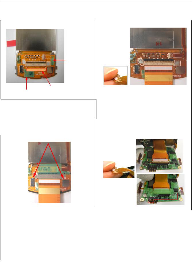
Exploded View and Parts List
5-5. LCD KIT
1 |
|
2 |
|
<LCD MASKING TAPE B>
<SLIDE FPCB MASKING TAPE> <LCD MASKING TAPE A>
1)Attach the MASKING TAPE A,B on LDI
2)Attach the SLIDE FPCB MASKING
TAPE |
|
|
|
|
|
|
|
|
|
|
|
|
|
|
|
|
|
|
|
|
|
|
|
|
|
|
|
|
|
|
|
|
|
|
|
|
|
|
|
|
|
|
|
|
|
|
|
|
|
|
|
|
|
|
|
|
||
caution |
|
|
|
|
|
|
|
|
|
|
|
|
|
|
|
|
|
|
|
|
|
|
|
|
|
|
|
|
|
|
|
|
|
|
|
|
|
|
|
|
|
|
|
|
|
|
|
|
|
|
|
|
|
|
|
|
||
|
|
|
|
|
|
|
|
|
|
|
|
|
|
|
|
|
|
|
|
|
|
|
|
|
|
|
|
|
|
|
|
|
|
|
|
|
|
|
|
|
|
|
|
|
|
|
|
|
1) |
With the picture it inserts the FPCB |
||||||||
1) The TAPE when attaching, it considers to |
||||||||||||||||||||||||||||||||||||||||||||||||||||||||||
caution |
||||||||||||||||||||||||||||||||||||||||||||||||||||||||||
the guide line of the picture and it attaches. |
1) |
Attention. Don't crumple or crack the FPCB |
||||||||||||||||||||||||||||||||||||||||||||||||||||||||
3 |
|
< Attach closely > |
4 |
|
|
|
|
|
|
|||||||||||||||||||||||||||||||||||||||||||||||||
|
|
|
|
|
|
|
|
|
|
|
|
|
|
|
|
|
|
|
|
|
|
|
|
|
|
|
|
|
|
|
|
|
|
|
|
|
|
|
|
|
|
|
|
|
|
|
|
|
|
|
|
|
|
|
|
|
|
|
|
|
|
|
|
|
|
|
|
|
|
|
|
|
|
|
|
|
|
|
|
|
|
|
|
|
|
|
|
|
|
|
|
|
|
|
|
|
|
|
|
|
|
|
|
|
|
|
|
|
|
|
|
|
|
|
|
|
|
|
|
|
|
|
|
|
|
|
|
|
|
|
|
|
|
|
|
|
|
|
|
|
|
|
|
|
|
|
|
|
|
|
|
|
|
|
|
|
|
|
|
|
|
|
|
|
|
|
|
|
|
|
|
|
|
|
|
|
|
|
|
|
|
|
|
|
|
|
|
|
|
|
|
|
|
|
|
|
|
|
|
|
|
|
|
|
|
|
|
|
|
|
|
|
|
|
|
|
|
|
|
|
|
|
|
|
|
|
|
|
|
|
|
|
|
|
|
|
|
|
|
|
|
|
|
|
|
|
|
|
|
|
|
|
|
|
|
|
|
|
|
|
|
|
|
|
|
|
|
|
|
|
|
|
|
|
|
|
|
|
|
|
|
|
|
|
|
|
|
|
|
|
|
|
|
|
|
|
|
|
|
|
|
|
|
|
|
|
|
|
|
|
|
|
|
|
|
|
|
|
|
|
|
|
|
|
|
|
|
|
|
|
|
|
|
|
|
|
|
|
|
|
|
|
|
|
|
|
|
|
|
|
|
|
|
|
|
|
|
|
|
|
|
|
|
|
|
|
|
|
|
|
|
|
|
|
|
|
|
|
|
|
|
|
|
|
|
|
|
|
|
|
|
|
|
|
|
|
|
|
|
|
|
|
|
|
|
|
|
|
|
|
|
|
|
|
|
|
|
|
|
|
|
|
|
|
|
|
|
|
|
|
|
|
|
|
|
|
|
|
|
|
|
|
|
|
|
|
|
|
|
|
|
|
|
|
|
|
|
|
|
|
|
|
|
|
|
|
|
|
|
|
|
|
|
|
|
|
|
|
|
|
|
|
|
|
|
|
|
|
|
|
|
|
|
|
|
|
|
|
|
|
|
|
|
|
|
|
|
|
|
|
|
|
|
|
|
|
|
|
|
|
|
|
|
|
|
|
|
|
|
|
|
|
|
|
|
|
|
|
|
|
|
|
|
|
|
|
|
|
|
|
|
|
|
|
|
|
|
|
|
|
|
|
|
|
|
|
|
|
|
|
|
|
|
|
|
|
|
|
|
|
|
|
|
|
|
|
|
|
|
|
|
|
|
|
|
|
|
|
|
|
|
|
|
|
|
|
|
|
|
|
|
|
|
|
|
|
|
|
|
|
|
|
|
|
|
|
|
|
|
|
|
|
|
|
|
|
|
|
|
|
|
|
|
|
|
|
|
|
1) |
With the picture it attaches green |
|
|
|
1) |
With the picture it inserts FPCB in |
|||
|
insulation TAPE |
|||
|
|
CONNECTOR after fold up edge of |
||
2) |
With the picture it attaches siver electric |
|
||
|
FPCB. |
|||
|
conduction TAPE. |
|
||
|
2) With the picture it attaches green |
|||
caution |
|
insulation Tape. |
||
caution |
||||
1) |
The TAPE when attaching, it considers to |
|||
|
the guide line of the picture and it |
1) |
Attention. Don't crumple or crack FPCB |
|
|
attaches. |
2) |
The TAPE when attaching, it considers to |
|
2) |
Attach closely the siver electric conduction |
|
the guide line of the picture and it |
|
|
TAPE on the bottom. |
|
attaches. |
|
5-12
SAMSUNG Proprietary-Contents may change without notice
This Document can not be used without Samsung's authorization
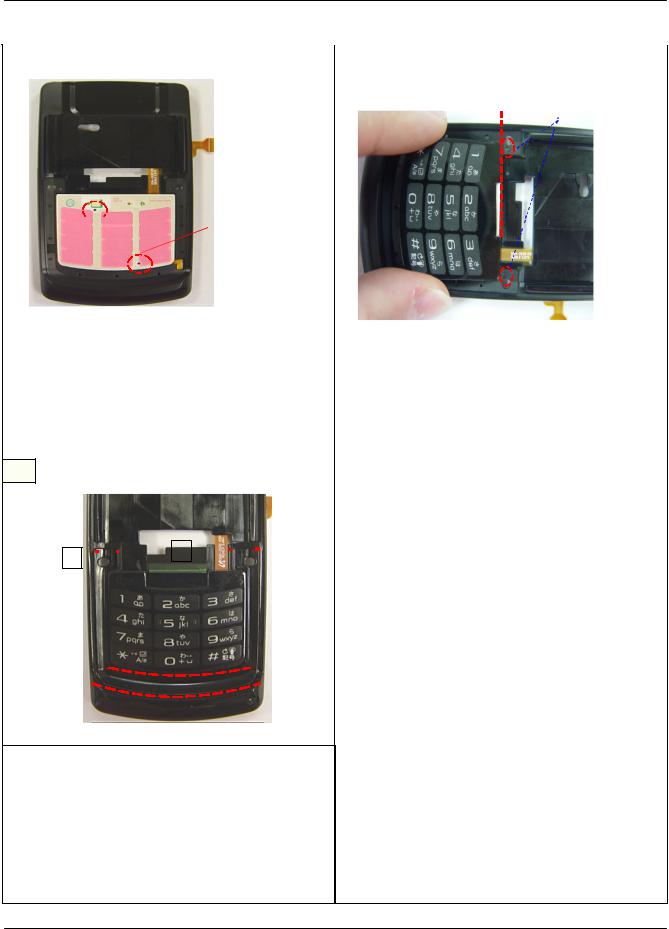
Exploded View and Parts List
5 |
|
6 |
|
<GUIDE HOLE>


 <GUIDE HOLE>
|
|
|
|
|
|
|
|
|
|
|
|
|
|
|
|
|
|
|
|
|
|
|
|
|
|
|
|
|
|
|
|
|
|
|
|
|
|
|
|
|
|
|
|
|
|
|
|
|
|
|
|
|
|
|
|
|
|
|
|
|
|
|
|
|
|
|
|
1)Insert the FPCB of MIC in front right side |
|
|
|
lowwer hole and Attach the 3*4 KEY PCB In |
|
|
|
3*4 KEY safe arrival surface of FRONT |
|
|
|
caution |
|
|
|
1) With the picture it attaches 3*4 KEY PAD |
|||
1) The TAPE when attaching, it considers to |
|||
caution |
|||
|
|||
the guide line of the picture and it |
1) Attach the 3*4 KEY PAD according to |
||
|
|||
attaches. |
GUIDE HOLE. |
||
7
|
|
|
|
|
|
|
|
|
|
|
|
|
|
|
|
|
|
|
|
|
|
|
|
|
|
|
|
|
|
||||||
|
|
|
|
|
|
|
|
|
|
|
|
|
|
|
|||||||||||||||||||||
|
|
|
|
|
|
|
|
|
|
|
|
|
|
|
|
|
|
|
|
|
|
|
|
|
|
|
|
|
|
|
|
|
|
|
|
|
|
|
|
|
|
|
|
|
|
|
|
|
|
|
|
|
|
|
|
|
|
|
|
|
|
|
|
|
|
|
|
|
|
|
|
|
|
|
|
|
|
|
|
|
|
|
|
|
|
|
|
|
|
|
|
|
|
|
|
|
|
|
|
|
|
|
|
|
|
|
|
|
|
|
|
|
|
|
|
|
|
|
|
|
|
|
|
|
|
|
|
|
|
|
|
|
|
|
|
|
|
|
|
|
|
|
|
|
|
|
|
|
|
|
|
|
|
|
|
|
|
|
|
|
|
|
|
|
|
|
|
|
|
|
|
|
|
|
|
|
|
|
|
|
|
|
|
|
|
|
|
|
|
|
|
|
|
|
|
|
|
|
|
|
|
|
|
|
|
|
|
|
|
|
|
|
|
|
|
|
|
|
|
|
|
|
|
|
|
|
|
|
|
|
|
|
|
|
|
|
|
|
|
|
|
|
|
|
|
|
|
|
|
|
|
|
|
|
|
|
|
|
|
|
|
|
|
|
|
|
|
|
|
|
|
|
|
|
|
|
|
|
|
|
|
|
|
|
|
|
|
|
|
|
|
|
|
|
|
|
|
|
|
|
|
|
|
|
|
|
|
|
|
|
|
|
|
|
|
|
|
|
|
|
|
|
|
|
|
|
|
|
|
|
|
|
|
|
|
|
|
|
|
|
|
|
|
|
|
|
|
|
|
|
|
|
|
|
|
|
|
|
|
1)With the picture it assembles FRONT BRACKET .
2)With the picture which attach a green
insulation 3*4 KEY NOISE Tape in same location.
caution
1)The TAPE when attaching, it considers to the guide line of the picture and it attaches.
5-13
SAMSUNG Proprietary-Contents may change without notice
This Document can not be used without Samsung's authorization

6. MAIN Electrical Parts List
|
SEC CODE |
Design LOC |
Discription |
STATUS |
|
0403-001511 |
ZD540 |
DIODE-ZENER |
SA |
|
0403-001547 |
ZD204 |
DIODE-ZENER |
SA |
|
0404-001172 |
D100 |
DIODE-SCHOTTKY |
SA |
|
0404-001172 |
D101 |
DIODE-SCHOTTKY |
SA |
|
0404-001172 |
D102 |
DIODE-SCHOTTKY |
SA |
|
0406-001190 |
ZD201 |
DIODE-TVS |
SA |
|
0406-001190 |
ZD202 |
DIODE-TVS |
SA |
|
0406-001190 |
ZD203 |
DIODE-TVS |
SA |
|
0407-001002 |
D500 |
DIODE-ARRAY |
SA |
|
0504-001113 |
TR101 |
TR-DIGITAL |
SA |
|
0504-001113 |
TR502 |
TR-DIGITAL |
SA |
|
0504-001151 |
U701 |
TR-DIGITAL |
SA |
|
0505-001889 |
U502 |
FET-SILICON |
SA |
|
0601-001909 |
LED400 |
LED |
SA |
|
0801-002995 |
U406 |
IC-CMOS LOGIC |
SA |
|
1001-001414 |
U304 |
IC-ANALOG SWITCH |
SA |
|
1001-001414 |
U305 |
IC-ANALOG SWITCH |
SA |
|
1003-001716 |
U504 |
IC-EL DRIVER |
SA |
|
1006-001322 |
U102 |
IC-LINE TRANSCEIVER |
SA |
|
1108-000071 |
UME400 |
IC-MCP |
SA |
|
1201-002195 |
U303 |
IC-AUDIO AMP |
SA |
|
1201-002240 |
U302 |
IC-AUDIO AMP |
SA |
|
1201-002288 |
PAM600 |
IC-POWER AMP |
SA |
|
1201-002347 |
PAM700 |
IC-POWER AMP |
SA |
|
1203-003046 |
U403 |
IC-BATTERY |
SA |
|
1203-003523 |
U200 |
IC-POSI.FIXED REG. |
SA |
|
1203-003531 |
U505 |
IC-POSI.FIXED REG. |
SA |
|
1203-003728 |
U501 |
IC-VOL. DETECTOR |
SA |
|
1203-003742 |
U405 |
IC-BATTERY |
SA |
|
1203-003754 |
U508 |
IC-POSI.FIXED REG. |
SA |
|
1203-004102 |
U503 |
IC-POWER SUPERVISOR |
SA |
|
1203-004394 |
U404 |
IC-MULTI REG. |
SA |
|
1203-004473 |
U401 |
IC-POSI.FIXED REG. |
SA |
|
1204-002138 |
U301 |
IC-MELODY |
SA |
|
1205-002568 |
U507 |
IC-SWITCH |
SA |
|
1205-002645 |
U601 |
IC-TRANSCEIVER |
SA |
|
1205-002781 |
U700 |
IC-RECEIVER |
SA |
|
|
|
6-1 |
|
|
|
SAMSUNG Proprietary-Contents may change without notice |
|
|
This Document can not be used without Samsung's authorization

Main Electrical Parts List
SEC CODE |
Design LOC |
Discription |
STATUS |
1205-002790 |
UCP101 |
IC-MODEM |
SA |
1209-001577 |
U702 |
IC-DETECTOR |
SA |
1209-001615 |
U103 |
IC-SENSOR |
SA |
1404-001224 |
VR100 |
THERMISTOR-NTC |
SA |
1405-001108 |
VR101 |
VARISTOR |
SA |
1405-001108 |
VR201 |
VARISTOR |
SA |
1405-001108 |
VR202 |
VARISTOR |
SA |
1405-001108 |
VR203 |
VARISTOR |
SA |
1405-001108 |
VR204 |
VARISTOR |
SA |
1405-001108 |
VR205 |
VARISTOR |
SA |
1405-001108 |
VR206 |
VARISTOR |
SA |
1405-001108 |
VR207 |
VARISTOR |
SA |
1405-001108 |
VR215 |
VARISTOR |
SA |
1405-001108 |
VR217 |
VARISTOR |
SA |
1405-001108 |
VR400 |
VARISTOR |
SA |
1405-001108 |
VR401 |
VARISTOR |
SA |
2007-000140 |
R203 |
R-CHIP |
SA |
2007-000145 |
R616 |
R-CHIP |
SA |
2007-000148 |
R511 |
R-CHIP |
SA |
2007-000151 |
R578 |
R-CHIP |
SA |
2007-000156 |
R413 |
R-CHIP |
SA |
2007-000157 |
R538 |
R-CHIP |
SA |
2007-000162 |
R412 |
R-CHIP |
SA |
2007-000171 |
R200 |
R-CHIP |
SA |
2007-000171 |
R232 |
R-CHIP |
SA |
2007-000171 |
R442 |
R-CHIP |
SA |
2007-000171 |
R702 |
R-CHIP |
SA |
2007-000242 |
R371 |
R-CHIP |
SA |
2007-000242 |
R372 |
R-CHIP |
SA |
2007-000690 |
R569 |
R-CHIP |
SA |
2007-000758 |
R501 |
R-CHIP |
SA |
2007-001119 |
R376 |
R-CHIP |
SA |
2007-001292 |
R612 |
R-CHIP |
SA |
2007-001313 |
R607 |
R-CHIP |
SA |
2007-001329 |
R201 |
R-CHIP |
SA |
2007-003022 |
R436 |
R-CHIP |
SA |
2007-003022 |
R437 |
R-CHIP |
SA |
|
|
6-2 |
|
|
|
|
|
|
SAMSUNG Proprietary-Contents may change without notice |
|
|
This Document can not be used without Samsung's authorization
 Loading...