


 Loading...
Gas Cooktop
Installation manual
NA30*5310F* / NA36*5310F*
Install_NA30R5310FG_AA_DG68-01133A-00_EN.indd 1 |
|
|
2019-04-12 12:13:30 |
|
|
||
|
|
|
|

WARNING: If the information in this manual is not followed exactly, a fire or explosion may result causing property damage, personal injury or death.
•DO NOT store or use gasoline or other flammable vapors and liquids in the vicinity of this or any other appliance.
•WHAT TO DO IF YOU SMELL GAS:
--DO NOT try to light any appliance. --DO NOT touch any electrical switch.
--DO NOT use any phone in your building.
--Immediately call your gas supplier from a neighbor’s phone. Follow the gas supplier’s instructions.
--If you cannot reach your gas supplier, call the fire department.
•Installation and service must be performed by a qualified installer, service agency, or the gas supplier.
2 English
Contents
Before you begin |
3 |
|
|
Important safety information |
3 |
|
|
Gas cooktop components |
8 |
|
|
What’s in the box |
8 |
Installation requirements |
10 |
|
|
Pre-installation checklist |
10 |
Location requirements |
10 |
Gas supply requirements |
12 |
Special gas requirements (gas models sold in Massachusetts) |
13 |
Electrical requirements |
13 |
Installation instructions |
14 |
|
|
Installing your gas cooktop |
14 |
Step 1. Unpack the cooktop |
14 |
Step 2. Installing the cooktop |
14 |
Step 3. Connect the cooktop to gas supply |
15 |
Step 4. Check for gas leaks |
16 |
Step 5. Electrical connections |
17 |
Step 6. Assemble the cooktop burners |
17 |
Step 7. Check the ignition of cooktop burners |
19 |
Step 8. Checking the flame quality |
19 |
Step 9. Install the grates |
20 |
Step 10. Final installation checklist |
22 |
LP (Propane) conversion instruction |
22 |
Supplied parts |
23 |
Converting the pressure regulator |
24 |
Converting the cooktop burners |
25 |
Adjusting low flame setting on cooktop burners |
26 |
Install_NA30R5310FG_AA_DG68-01133A-00_EN.indd 2 |
|
|
2019-04-12 12:13:30 |
|
|
||
|
|
|
|

Before you begin
About this manual
READ THESE INSTRUCTIONS COMPLETELY AND CAREFULLY.
Important note to the installer
•Read all instructions contained in these installation instructions before installing the cooktop.
•Remove all packing materials from the cooktop compartments before connecting the electric and gas supply to the cooktop.
•Observe all governing codes and ordinances.
•Be sure to leave these instructions with the consumer.
•Installation of this appliance requires basic mechanical skills.
•Proper installation is the responsibility of the installer.
•Product failure due to improper installation is not covered under the Warranty.
Important note to the consumer
Keep these instructions with your user manual for future reference.
•As when using any appliance generating heat, there are certain safety precautions you should follow.
•Be sure your cooktop is installed and grounded properly by a qualified installer or service technician.
•Make sure the wall coverings around the cooktop can withstand the heat generated by the cooktop.
•Cabinet storage space above the cooktop burners should be a minimum of 30 in (76.2 cm).
Important note to the servicer
The electrical diagram is attached inside the burner box.
Important safety information
READ ALL INSTRUCTIONS BEFORE USING THIS APPLIANCE
•All electrical and gas equipment with moving parts can be dangerous. Please read the important safety instructions for this appliance in this manual. The instructions must be followed to minimize the risk of injury, death, or property damage.
•Save this manual. Please Do Not Discard.
Symbols used in this manual
 WARNING
Hazards or unsafe practices that may result in severe personal injury or death.
 CAUTION
Hazards or unsafe practices that may result in electric shock, personal injury, or property damage.
 NOTE
NOTE
Useful tips and instructions.
These warning icons and symbols are here to prevent injury to you and others. Please follow them explicitly. After reading this section, keep it in a safe place for future reference.
English 3
begin you Before
Install_NA30R5310FG_AA_DG68-01133A-00_EN.indd 3 |
|
|
2019-04-12 12:13:30 |
|
|
||
|
|
|
|

information safety Important
Important safety information
California Proposition 65 Warning
 WARNING
Cancer and Reproductive Harm - www.P65Warnings.ca.gov
Commonwealth of Massachusetts
•This product must be installed by a licensed plumber or gas fitter qualified or licensed by the State of Massachusetts. When using ball-type gas shut-off valves, you must use the T-handle type. Multiple flexible gas lines must not be connected in series.
General safety
 WARNING
To reduce the risk of fire, electric shock, personal injuries, and/or death, obey the following precautions.
• Do not touch any part of the cooktop, including but not limited to, cooktop burners, during or
immediately after cooking.
• Know the location of the gas shut-off valve and how to shut it off.
•Make sure the hold down brackets are properly installed on the cooktop. See the installation instructions for more information.
•Do not let children near, in, or on the cooktop. Do not let children play with the cooktop or any part(s) of the cooktop. Do not leave children unattended in an area where the cooktop is in use.
•Remove all packaging materials from the cooktop before operating to prevent ignition of these materials. Keep all packaging materials out of children’s reach. Properly dispose the packaging materials after the cooktop is unpacked.
•Do not store any object of interest to children on the cooktop or backguard of the cooktop. Children climbing on the cooktop to reach items could be killed or seriously injured.
4 English
•Do not operate the cooktop if the cooktop or any part of the cooktop is damaged, malfunctioning, or missing parts.
•Do not use the cooktop as a space heater. This cooktop is to be used for cooking purposes only.
•Use only dry pot holders.
•Do not use the cooktop to heat unopened food containers.
•Unplug or disconnect power before servicing.
Fire safety
 WARNING
To reduce the risk of fire, electric shock, personal injuries, and/or death, obey the following precautions.
• Do not store, place, or use flammable or
combustible materials such as paper, plastic,
pot holders, linens, curtains, gasoline or other
flammable vapors or liquids near the cooktop.
• Do not wear loose fitting or hanging garments while using the cooktop.
•To avoid grease buildup, regularly clean the vents.
•Do not let pot holders or other flammable materials touch a heating element. Do not use a towel or other bulky cloths in place of a pot holder.
•Do not use water on a grease fire. To put out a grease fire, turn off the heat source and smother the fire with a tight-fitting lid or use a multipurpose dry chemical or foam-type fire extinguisher.
•Do not heat unopened food containers - buildup of pressure may cause container to burst and result in injury.
Install_NA30R5310FG_AA_DG68-01133A-00_EN.indd 4 |
|
|
2019-04-12 12:13:31 |
|
|
||
|
|
|
|

Gas safety
 WARNING
To reduce the risk of fire, electric shock, personal injuries, and/or death, obey the following precautions.
If you smell gas:
•Close the valve and do not use the cooktop.
•Do not light a match, candle, or cigarette.
•Do not turn on any gas or electric appliances.
• Do not touch any electrical switches or plug a power cord into an outlet.
• Do not use any phone in your building.
• Evacuate the room, building, or area of all occupants.
• Immediately call your gas supplier from a neighbor’s phone. Follow the gas supplier’s instructions.
•If you cannot reach your gas supplier, call the fire department.
Checking for gas leaks
•Leak testing of the appliance shall be conducted according to the manufacturer’s instructions. Do not use a flame to check for gas leaks. Use a brush to spread a soapy water mixture around the area you are checking. If there is a gas leak, you will see small bubbles in the soapy water mixture at the leak point.
Electrical and grounding safety
 WARNING
To reduce the risk of fire, electric shock, personal injuries, and/or death, obey the following precautions.
• Plug into a grounded 3-prong outlet.
• Do not remove the ground prong.
• Do not use an adapter or an extension cord.
• Do not use a damaged power plug, power cord, or loose power outlet.
•Do not modify the power plug, power cord, or power outlet in any way.
•Do not put a fuse in a neutral or ground circuit.
•Use a dedicated 120-volt, 60-Hz, 20-amp, AC, fused electrical circuit for this cooktop. A time-delay fuse or circuit breaker is recommended. Do not plug more than one appliance into this circuit.
•Do not connect the ground wire to plastic plumbing lines, gas lines, or hot water pipes.
•This cooktop must be Earth grounded. In the event of a malfunction or breakdown, grounding will reduce the risk of electrical shock by providing a path for the electric current. This cooktop is equipped with a cord having a grounding plug. The plug must be firmly plugged into an outlet that is properly installed and grounded in accordance with the local codes and ordinances. If you are unsure whether your electrical outlet is properly grounded, have it checked by a licensed electrician.
•The cooktop is supplied with a 3-pronged grounded plug. This cord must be plugged into a mating, grounded 3-prong outlet that meets all local codes and ordinances. If codes permit the use of a separate ground wire, we recommend that a qualified electrician determine the proper path for this ground wire.
•Electrical service to the cooktop must conform to local codes. Barring local codes, it should meet the latest ANSI/NFPA No. 70 – Latest Revision (for the U.S.) or the Canadian Electrical Code CSA C22.1 – Latest Revisions.
•It is the personal responsibility of the cooktop owner to provide the correct electrical service for this cooktop.
English 5
information safety Important
Install_NA30R5310FG_AA_DG68-01133A-00_EN.indd 5 |
|
|
2019-04-12 12:13:31 |
|
|
||
|
|
|
|

information safety Important
Important safety information
Installation safety
 WARNING
To reduce the risk of fire, electric shock, personal injuries, and/or death, obey the following precautions.
•Have your cooktop installed and properly grounded by a qualified installer, in accordance with the installation instructions. Any adjustment and service should be performed only by qualified gas cooktop installers or service technicians.
•Do not attempt to service, modify, or replace your cooktop or any part of your cooktop unless it is specifically recommended in this manual. All other service should be referred to a qualified technician.
•Always use new flexible connectors when installing a gas appliance. Do not use old flexible connectors.
•Make sure the hold down brackets are properly installed on the cooktop. See the installation instructions for more information.
•Remove all tape and packaging materials.
•Remove all accessories from the cooktop. Grates and griddles are heavy. Use caution when handling them.
•Make sure no parts came loose during shipping.
6 English
•Make sure your cooktop is correctly installed and adjusted by a qualified service technician or installer for the type of gas (natural or LP) you will use. For your cooktop to utilize LP gas, the installer must replace the 5 cooktop burner orifices with the provided LP orifice set, and reverse the GPR adapter. These adjustments must be made by a qualified service technician in accordance with the manufacturer’s instructions and all codes and requirements of the authority having jurisdiction. The qualified agency performing this work assumes the gas conversion responsibility.
•Installation of this cooktop must conform with local codes or, in the absence of local codes, with the National Fuel Gas Code, ANSI Z223.1/NFPA.54, latest edition. In Canada, the Natural Gas and Propane Installation Code, CSA B149.1. This cooktop has been design-certified by ETL according to ANSI Z21.1, latest edition, and Canadian Gas Association according to CAN/CGA-1.1, latest edition.
Install_NA30R5310FG_AA_DG68-01133A-00_EN.indd 6 |
|
|
2019-04-12 12:13:31 |
|
|
||
|
|
|
|

Location safety
 WARNING
To reduce the risk of fire, electric shock, personal injuries, and/or death, obey the following precautions.
• This cooktop is for indoor, household use only. Do not install the cooktop in areas exposed to the weather and/or water.
• Do not install the cooktop in a place which is exposed to a strong draft.
•Select a location where a grounded, 3- prong outlet is easily accessible.
•If the cooktop is located near a window, do not hang long curtains or paper blinds on that window.
•For the cooktop to ventilate properly, there is enough clearance at the top, back, sides, and underneath the cooktop. The vents allow the necessary exhaust for the cooktop to operate properly with correct combustion.
•Make sure the wall coverings around the cooktop can withstand heat up to 194 °F (90 °C) generated by the cooktop.
•Cabinet storage above the surface of the cooktop should be avoided. If cabinet storage above the cooktop is necessary: allow a minimum clearance of 30 inches (76.2 cm) between the cooking surface and the bottom of cabinets.
Cooktop safety
 WARNING
To reduce the risk of fire, electric shock, personal injuries, and/or death, obey the following precautions.
• Make sure all burners are off when not in use. • Do not use aluminium foil to line the grates or
any part of the cooktop.
• Do not leave burners unattended on medium or
high heat settings.
• Before igniting, make sure all burner caps are properly in place and all burners are level.
•Always use the LITE position when igniting the burners and make sure the burners have ignited. If ignition fails, turn the knob to OFF and wait until the gas has dissipated.
•When you set a burner to simmer, do not turn the knob quickly. Make sure the flame stays on.
•Do not place any objects other than cookware on the cooktop.
•This cooktop is designed to cook with a wok or wok ring attachment. If foods are flamed, they should only be flamed under a ventilation hood that is on.
•Before removing or changing cookware, turn off the burners.
•Remove food and cookware immediately after cooking.
•Before removing any parts of the burner for cleaning, make sure the cooktop is off and completely cool.
•After cleaning the burner spreader, make sure it is completely dry before reassembling.
•To avoid carbon monoxide poisoning, do not pour water into the cooktop well while cleaning.
•Select cookware that is designed for top-cooktop cooking. Use cookware that is large enough to cover the burner grates. Adjust the burner flames so that the flames do not extend beyond the bottom of the cookware.
•To avoid cookware discoloration, deformity, and/or carbon monoxide poisoning, do not use cookware that is exceedingly larger than the grate.
•Make sure cookware handles are turned to the side or rear of the cooktop, but not over other cooktop burners.
English 7
information safety Important
Install_NA30R5310FG_AA_DG68-01133A-00_EN.indd 7 |
|
|
2019-04-12 12:13:31 |
|
|
||
|
|
|
|

components cooktop Gas
Important safety information
•Stand away from the cooktop while frying.
•Always heat frying oils slowly, and watch as they heat. If you are frying foods at high heat, carefully watch during the cooking process. If a combination of fats or oils is to be used during frying, mix them together before heating.
•Use a deep-fryer thermometer whenever possible. This prevents overheating the fryer beyond the smoking point.
•Use a minimum amount of oil when shallow pan-frying or deep-frying. Avoid cooking unthawed food or food with excessive amounts of ice.
•Before moving cookware full of fats or oils, make sure it has completely cooled.
•To prevent delayed eruptive boiling, always allow heated liquids to stand at least 20 seconds after you have turned off the burner so that the temperature in the liquid can stabilize. In the event of scalding, follow these first aid instructions:
1.Immerse the scaled area in cool or lukewarm water for at least 10 minutes.
2.Do not apply any creams, oils, or lotions.
3.Cover with a clean, dry cloth.
8 English
Gas cooktop components
What’s in the box
Parts supplied
Surface burner grates (2) * |
Surface burner grates (3) * |
Cooktop burners and |
30” Model : NA30R5310F* |
36” Model : NA36R5310F* |
caps (5) * |
|
|
36” Model : NA36R5310F* |
Cooktop burners and |
Screw (6) |
Regulator (1) * |
caps (4) * |
(M4L10 2 ea, M4 L16 2 ea, |
|
30” Model : NA30R5310F* |
W3/16 L75 2 ea) |
|
Hold down brackets (2) * |
Foam tape |
•Make sure you have received all of the supplied parts shown above.
•If your cooktop was damaged during shipping or you do not have all of the supplied parts, contact your local retailer.
 NOTE
NOTE
If you need an accessory marked with an * (asterisk), please contact the Samsung Call Center using the phone number listed on the last page of this manual or visit our on-line parts web site at www.samsungparts.com.
Install_NA30R5310FG_AA_DG68-01133A-00_EN.indd 8 |
|
|
2019-04-12 12:13:32 |
|
|
||
|
|
|
|

Parts needed
Gas line shut-off |
Flexible metal |
Flare union adapter Flare union adapter |
|
valve |
appliance connector |
¾ in or ½ in (NPT) x |
½ in (NPT) x ½ in |
|
½ in (ID) x 5 ft |
½ in (ID) |
(ID) |
135-degree elbow |
90-degree elbow |
(optional) |
(optional) |
Tools needed
Flat-blade |
Phillips screwdriver |
Open-end or |
|
Pipe wrench (2) |
||||
screwdriver |
|
|
|
|
|
adjustable wrench |
|
|
|
|
|
|
|
|
|
|
|
|
|
|
|
|
|
|
|
|
|
|
|
|
|
|
|
|
|
¼" Nut driver |
Pencil and ruler |
Level |
Pipe joint compound |
Utility knife |
Soapy water |
Pliers |
Saber saw |
|
solution |
|
|
English 9
components cooktop Gas
Install_NA30R5310FG_AA_DG68-01133A-00_EN.indd 9 |
|
|
2019-04-12 12:13:33 |
|
|
||
|
|
|
|

requirements Installation
Installation requirements
Pre-installation checklist
1.When preparing cooktop opening, make sure the inside of the cabinet, and the cooktop do not interfere with each other.
2.Remove packing materials, grate boxes, regulator with literature, and literature package from the cooktop before beginning installation.
Location requirements
BEFORE YOU BEGIN to install this appliance, refer to the following information, dimensions, and clearances. These dimensions must be met for safe use of the cooktop. The location of the electrical outlet and gas piping may be adjusted to meet the following dimensions and clearances.
 CAUTION
This cooktop has been designed to comply with the maximum allowable wood cabinet temperature of 194 °F (90 °C). Make sure the wall covering, countertops, and cabinets around the cooktop can withstand the heat (up to 194 °F [90 °C]) generated by the cooktop. If not, discoloration, delamination, or melting may occur.
Maintain the following minimum clearance dimensions
|
|
|
|
|
|
|
|
|
|
|
|
|
|
|
|
|
|
|
13” MAX. |
|
|
|
|
|
|
13” MAX. |
|
|
|
|
|
|
|
||||
(330 mm) |
|
|
|
|
18” MIN |
(330 mm) |
|
|
|
|
|
18” MIN |
||||||
|
|
|
|
|
|
|
|
|
|
|
|
|
||||||
|
|
|
|
|
|
(457 mm) |
|
|
|
|
|
|
|
(457 mm) |
||||
|
|
|
|
|
|
|
|
|
|
|
|
|
|
|
|
|
|
|
|
|
|
|
30” MIN |
|
|
|
|
|
|
|
30” |
|
MIN |
|
|
|
|
|
|
|
|
(762 mm) |
|
12” MIN |
|
|
|
|
(762 mm) |
|
12” |
|||||
|
|
|
|
|
|
|
|
|
|
|
|
|
|
|
||||
|
|
|
|
|
|
|
|
|
||||||||||
|
|
|
|
|
|
|
(304.8 mm) |
|
|
|
|
|
|
|
|
(304.8 mm) |
||
|
27/8” MIN |
|
|
|
|
|
|
|
33/8” Min |
|
|
|
|
12” |
||||
(73.0 mm) |
|
|
12” MIN |
|
(85.7 mm) |
|
|
|
|
|||||||||
|
|
|
|
|
(304.8 mm) |
|
|
|
|
|
|
(304.8 mm) |
||||||
|
|
|
|
|
|
|
|
|
|
|||||||||
|
|
|
30” - NA30*5310F* |
|
|
|
36” - NA36*5310F* |
|||||||||||
|
|
|
|
|
|
|
|
|
|
|
|
|
|
|
|
|
|
|
10 English
 NOTE
NOTE
All horizontal clearances must be maintained for a minimum of 18” (457 mm) above the cooking surface.
7/16”
(11.1 mm)
39/16” |
(90.5 mm) |
DRAWER
Electrical outlet 12” (30.5 cm) minimum below countertop 
 NOTE
NOTE
Allow 7/16” minimum vertical clearance from the cooktop bottom (or 39/16” minimum depth from the countertop) to any combustible surfaces, including the upper edge or a drawer installed below the cooktop.
Installation over built-in oven
See built-in oven installation for complete installation instructions.
|
5” To Center of 2” Dia. |
|
Hole From Countertop |
90° Elbow |
2” Dia. Hole |
|
|
|
(207/8” from front |
Cabinet Sides |
of countertop to |
hole Center |
View from Front of Cooktop
Install_NA30R5310FG_AA_DG68-01133A-00_EN.indd 10 |
|
|
2019-04-12 12:13:34 |
|
|
||
|
|
|
|
Overall cooktop dimensions |
|
|
|
|
|
|
|
30” Model |
|
|
|
36” Model |
|
|
A |
|
|
|
A |
|
E |
|
|
E |
|
|
|
D |
|
F |
|
|
D |
|
F |
|
|
|
B |
|
|
B |
|
C |
|
|
C |
|
|
|
|
|
|||
Model |
|
NA30*5310F* |
NA36*5310F* |
|||
A |
|
|
30” (762 mm) |
36” (914.4 mm) |
||
B |
|
|
281/8” (715 mm) |
3311/16” (855.4 mm) |
||
C |
|
193/8” (492.1 mm) |
187/8” (479.1 mm) |
|||
D |
|
|
21” (533 mm) |
21” (533 mm) |
||
E (Countertop to grate surface) |
|
29/16” (65 mm) |
29/16” (65 mm) |
|||
F (Chassis Height) |
|
31/8” (79.5 mm) |
31/8” (79.5 mm) |
|||
Cutout dimensions of countertop |
|
|
|
|
|
|
Vertical |
Rear wall |
|
|
|
|
|
|
|
|
|
|
|
|
combustible |
|
|
|
|
|
|
surface |
|
|
|
|
|
|
|
|
|
|
|
J |
|
G |
|
|
I |
|
|
|
|
H |
|
|
|
|
|
|
|
J |
Minimum distance to combustible side |
|||
|
|
|
wall above countertop (both sides) |
|
||
Model |
(G) Min. |
|
(H) Min. |
(I) Min. |
(J) Min. |
|
NA30*5310F* |
27/8” (73 mm) |
195/8” (498.5 mm) |
281/2” (723.9 mm) |
12” (304.8 mm) |
||
NA36*5310F* |
33/8” (85.7 mm) |
191/8” (485.8 mm) |
337/8” (860.4 mm) |
12” (304.8 mm) |
||
Installation dimensions with downdraft hood
 NOTE
NOTE
Make sure the clearance dimensions when you install the cooktop with downdraft hood.
19/16” (40 mm) Min.

 Cooktop frame to downdraft hood
Cooktop
 (K) Cutout to downdraft hood
Downdraft Hood
19/16” (40 mm) Min.
36” Model |
30” Model |
Model |
(K) Min. |
NA30*5310F* |
27/16” (62 mm) |
NA36*5310F* |
3” (76 mm) |
English 11
requirements Installation
Install_NA30R5310FG_AA_DG68-01133A-00_EN.indd 11 |
|
|
2019-04-12 12:13:34 |
|
|
||
|
|
|
|

requirements Installation
Installation requirements
Single Oven Under counter
01 |
02 |
|
|
A |
H |
|
|
E |
G |
|
|
|
C |
D |
F |
|
|
|
B |
01This cooktop can be installed above any Samsung single built-in oven. Refer to installation manual of oven.
02Gas and Electrical Connections for Gas Cooktop Must be Located in an Adjacent Accessible Location to the Right.
|
Size |
|
|
A |
Min. 33/4” (9.5 cm) |
B |
4” (10.1 cm) |
CMin. 281/2” / Max. 285/8” (Min. 72.4 cm / Max. 72.7 cm)
DMin. 1” / Max. 11/4” (Min. 2.5 cm / Max. 3.2 cm)
EMin. 271/4” / Max. 273/8” (Min. 69.2 cm / Max. 69.5 cm)
F |
24” (61 cm) |
|
|
G |
Min. 22” (Min 55.9 cm) |
|
|
H |
Max. 91/2” (Max. 24.1 cm) – Junction Box |
12 English
Utility locations and dimensions
|
|
|
|
|
|
|
|
|
|
|
|
|
|
|
|
|
|
|
|
|
|
|
|
|
|
Front of unit |
|
|
Front of cooktop |
|
|
|
|
||||||||||||
|
|
|
|
|
|
|
|
|
|
|
|
|
|
|
|
|
|
|
|
|
|
|
|
|
|
|
|
|
|
|
|
|
|
|
|
|
|
|
|
|
|
|
|
|
|
|
|
|
|
|
|
|
|
|
|
|
|
|
|
|
|
|
|
|
|
|
|
|
|
|
|
|
|
|
|
|
|
|
|
|
|
|
|
|
|
|
|
|
|
|
|
|
|
|
|
|
|
|
|
|
|
|
|
|
|
|
|
|
|
|
|
|
|
|
|
|
|
|
|
|
|
|
|
|
|
|
|
|
|
|
|
|
|
|
|
|
|
|
|
|
|
|
|
|
|
|
|
|
|
|
|
|
|
|
|
|
|
|
11/4” |
|
|
|
|
|
|
|
|
|
|
|
|
|
|
|
|
|
|
|
|
|
|
(3.2 cm) |
|
|
|
|
|
|
|
|
|
|
|
|
|
Chassis |
|
|
|
|
|
|
|
|||
|
|
|
|
|
|
|
|
|
|
|
|
|
|
|
|
|
||||||
|
|
|
|
|
|
|
|
|
|
|
|
|
|
|
|
|
|
|
|
|
|
|
|
|
|
|
|
|
|
|
|
|
|
|
|
|
|
|
|
|
|
|
|
|
|
|
|
|
|
|
|
|
|
|
|
|
|
|
|
|
|
|
|
|
|
|
||
|
|
|
|
|
|
|
|
|
|
|
|
|
|
|
|
|
|
|
|
|
||
Power cord 393/8” |
|
|
|
|
|
|
|
|
|
|
|
|
|
|
|
|
|
|
||||
|
|
|
|
|
|
|
|
|
|
115/16” |
|
|
|
|
|
|||||||
(100.0 cm) long |
|
|
|
|
|
|
|
|
|
|
|
(5.0 cm) |
|
|
|
|
|
|
|
|||
|
|
|
|
|
|
|
|
|
|
|
|
|
|
|
|
|||||||
|
|
3/8”-18 NPT male |
* Gas inlet protrudes 19/16” (4.0 cm) |
|
|
|||||||||||||||||
|
|
|
|
|||||||||||||||||||
|
|
|
|
from bottom. |
|
|
||||||||||||||||
|
|
gas inlet |
|
|
|
|
||||||||||||||||
|
|
|
|
|
|
|
|
|
|
|
|
|
|
|
|
|
|
|
|
|
||
Gas supply requirements
Provide adequate gas supply
This cooktop is designed to operate at a pressure of 5 in (13 cm) of water column on natural gas or 10 in (25 cm) of water column on LP gas (propane or butane).
Make sure you are supplying your cooktop with the type of gas for which it is designed. Do not attempt to convert the appliance from the gas specified in this manual to a different gas without consulting the gas supplier.
This cooktop is convertible for use on natural or propane gas. If you decide to use this cooktop on LP gas, conversion must be made by a qualified LP installer before attempting to operate the cooktop.
For proper operation, the pressure of natural gas supplied to the regulator must be between 5 in and 13 in (13 cm and 33 cm) of water column.
For LP gas, the pressure supplied must be between 10 in and 13 in (25 cm and 33 cm) of water column.
When checking for proper operation of the regulator, the inlet pressure must be at least 1 in (2.5 cm) greater than the operating (manifold) pressure as given.
Install_NA30R5310FG_AA_DG68-01133A-00_EN.indd 12 |
|
|
2019-04-12 12:13:35 |
|
|
||
|
|
|
|
The pressure regulator located at the inlet of the cooktop manifold must remain in the supply line regardless of whether natural or LP gas is being used.
 NOTE
NOTE
•The cooktop comes from the factory with a regulator in the shipping carton. Use only the regulator provided. The regulator must be installed in the gas line that runs from the cooktop gas inlet to the gas shut off valve.
•An external manual shut-off valve must be installed between the gas inlet and the cooktop for the purpose of turning on or shutting off gas to the appliance.
•Be sure the connectors are installed when you need coupling by a qualified installer.
•Never reuse old connectors when installing the cooktop. The use of old connectors can cause gas leaks and personal injury. Always use new flexible connectors when installing a gas appliance.
Special gas requirements (gas models sold in Massachusetts)
COMMONWEALTH OF MASSACHUSETTS REQUIREMENTS:
 WARNING
Gas leaks may occur in your system, creating a dangerous situation.
–Gas leaks may not be detected by smell alone.
–Gas suppliers recommend you purchase and install a UL-approved gas detector. Gas detector should be installed in accordance with the manufacturers instructions.
•Cooktop must be installed by a qualified plumber or gas fitter by the State of Massachusetts.
•A T-handle manual gas valve MUST be installed in the gas supply line to your cooktop.
•If a flexible gas connector is used to install your cooktop, multiple flexible gas lines must not be connected in series.
Electrical requirements
 WARNING
•It is the owner’s responsibility to make sure that the electrical service meets electrical requirements and that he electrical outlet has been properly installed by a licensed electrician.
•To reduce the risk of fire, electric shock, or personal injury:
All cooktops
•Do not use an extension cord or adapter plug with this cooktop.
•This cooktop must be properly grounded.
•Check with a qualified electrician if you are in doubt as to whether your cooktop is properly grounded.
•Do not modify the plug provided with your cooktop — if it doesn’t fit the outlet, have a proper outlet installed by a qualified electrician.
•All wiring and grounding must be done in accordance with local codes or, in the absence of local codes, with the National Electrical Code, ANSI/NFPA No. 70 – Latest Revision (for the U.S.) or the Canadian Electrical Code CSA C22.1 – Latest Revisions and local codes and ordinances.
•Wiring diagram is located on the inside of the burner box.
•This cooktop is equipped with an electronic ignition system that will not operate if plugged into an outlet that is not properly polarized.
Gas cooktops
•All gas models are equipped with a power cord with an equipment-grounding conductor and a grounding plug.
•A 120-Volt, 60-Hz, AC, approved electrical service with 20-amp circuit breaker or time-delay fuse is required for all U.S. and Canadian models.
English 13
requirements Installation
Install_NA30R5310FG_AA_DG68-01133A-00_EN.indd 13 |
|
|
2019-04-12 12:13:35 |
|
|
||
|
|
|
|

instructions Installation
Grounding
•All cooktops must be grounded for personal safety.
•The plug must be firmly plugged into a three-prong outlet that is properly installed and grounded in accordance with all local codes and ordinances. In the event of a malfunction or breakdown, grounding will decrease the risk of electrical shock by providing a path for the electric current.
•Do not use a damaged power plug or loose wall outlet.
•Do not use an extension cord or adapter with this appliance
•Do not, under any circumstances, cut, modify, remove, or otherwise defeat the grounding (third) prong from the power cord. If the plug and the outlet do not match or you have any doubt, have a qualified electrician install the proper outlet. The customer should have the wall receptacle and circuit checked by a qualified electrician to make sure the receptacle is properly grounded.
•NEVER connect ground wire to plastic plumbing lines, gas lines, or water pipes.
 CAUTION
Failure to follow these instructions can result in death, fire, or electrical shock.
Additional installation requirements for mobile homes
The installation of appliances designed for mobile home installation must conform with the Manufactured Home Construction and Safety Standard, Title 24 CFR, Part 3280 (formerly the Federal Standard for Mobile Home Construction and Safety, Title 24, HUD, Part 280) or, when such standard is not applicable, the Standard for Manufactured Home Installations, latest edition (Manufactured Home Sites, Communities and Set-Ups), ANSI A225.1, latest edition, or with local codes. In Canada, mobile home installation must be in accordance with the current CAN/CSA Z240/MH Mobile Home Installation Code.
14 English
Installation instructions
Installing your gas cooktop
IMPORTANT:
Please read the following instructions, as well as the Important Safety Instructions section at the front of this manual, completely and carefully BEFORE installing and/or operating the gas cooktop. Improper installation, adjustment, service, or maintenance can cause personal injury or property damage.
 NOTE
NOTE
To ensure proper installation, we strongly recommend that you hire a professional installer.
Step 1. Unpack the cooktop
Remove all packaging materials. Failure to remove packaging materials could result in damage to the appliance.
Inventory all loose parts against the Parts supplied components listed on page 8.
Check for shipping damage and/or missing parts. Any damage and/or missing parts should be reported to your local retailer.
Step 2. Installing the cooktop
1. Locate electrical outlet and gas shut-off valve beneath cabinet.
2. Apply the foam tape around the edge of the cutout opening. Do not overlap the foam strips.
• The foam strip helps avoid damage to the underside of the cooktop from
debris and helps the cooktop sit flat on uneven counters.
3.Protect surface of cooktop
•Place a towel or tablecloth onto the countertop.
Install_NA30R5310FG_AA_DG68-01133A-00_EN.indd 14 |
|
|
2019-04-12 12:13:35 |
|
|
||
|
|
|
|
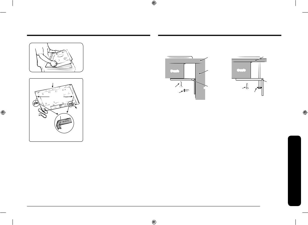
4.With bottom side first, gently put the cooktop down.
•Make sure the front of the countertop is parallel to the cooktop
•Make final check that all required clearances are met.
Correct installation
Front of unit
Hold down 

 bracket holes
Gas inlet
Power cord
5.Secure the cooktop to the countertop using the two provided hold-down brackets as shown.
Hold Down Bracket Installation
Hold down bracket install guide
Case 1. |
|
Case 2. |
|||
|
Countertop |
|
|
Countertop |
|
|
|
|
|
||
|
Side wall of |
|
|
|
|
|
|
|
|
||
Chassis |
undercounter |
Chassis |
|
|
|
cabinet |
|
|
|||
|
|
|
|||
|
|
|
|
||
|
|
|
|
Hold down |
|
M4 L10 screw |
Hold down |
|
|
bracket |
|
M4 L10 screw |
|||||
|
bracket |
||||
|
|
|
|
||
M4 L16 screw |
|
W3/16 L75 screw |
|||
Step 3. Connect the cooktop to gas supply
Shut off the main gas supply valve before disconnecting the old cooktop and leave it off until the new hookup has been completed. Don’t forget to relight the burner on other gas appliances when you turn the gas back on.
Because hard piping restricts movement of the cooktop, the use of a CSA International-certified flexible metal appliance connector is recommended unless local codes require a hard-piped connection.
 WARNING
If the information in this manual is not followed exactly, a fire or explosion may result, causing death, personal injury, or property damage.
–Do not store or use gasoline or other flammable vapors and liquids in the vicinity of this or any other appliance.
–WHAT TO DO IF YOU SMELL GAS:
•DO NOT light a match, candle, or cigarette.
•DO NOT try to light any appliance.
•DO NOT touch any electrical switch.
•DO NOT use any phone in your building.
•Clear the room, building, or area of all occupants.
English 15
instructions Installation
Install_NA30R5310FG_AA_DG68-01133A-00_EN.indd 15 |
|
|
2019-04-12 12:13:35 |
|
|
||
|
|
|
|

instructions Installation
Installation instructions
•Immediately call your gas supplier from a neighbor’s phone. Follow the gas supplier’s instructions.
•If you cannot reach your gas supplier, call the fire department.
–Installation and service must be performed by a qualified installer, service agency, or gas supplier.
–Do not install the cooktop without also installing the included gas regulator. Do not use the cooktop without the regulator installed.
–Ensure that the arrow on the regulator points in the direction of the gas flow, towards the cooktop.
–Do not apply excessive pressure when tightening gas connections and fittings.
–Test the gas lines for leaks as instructed before use. Do not use a flame to check for leaks.
Never use an old connector when installing a new cooktop. If the hard-piping method is used, you must carefully align the pipe; the cooktop cannot be moved after the connection is made.
To prevent gas leaks, apply pipe-joint compound or wrap pipe-thread tape with Teflon on all male (external) pipe threads.
1.Attach the gas pressure regulator (included with the cooktop) to the cooktop pipe nipple inlet. For tight installations, the regulator may be installed upstream from the pipe nipple, anywhere between the shut-off valve and the cooktop. For best performance, minimize gas pressure loss by attaching the regulator as close as possible to the cooktop gas inlet.
2.Complete connection of the gas supply to the cooktop by installing a flexible gas line between the pressure regulator and the shut-off valve.
 WARNING
Do not exceed 25 ft-lbs of torque when making gas line connections. Overtightening may crack the pressure regulator resulting in a gas leak.
16 English
Flexible connector hookup
Installer: Inform the consumer of the location of the gas shut-off valve.
Gas Shut-Off Valve |
|
|
|
|
|||||||||
|
|
|
|
|
|
|
½-in or ¾-in Gas |
||||||
|
|
|
|
|
|
|
|||||||
|
|
|
|
|
|
|
|||||||
|
|
|
|
|
|
|
Pipe |
|
|
|
|
||
|
|
|
|
|
|
|
|
|
|
|
|||
|
Cooktop |
|
|
|
Adapter |
|
|
|
|
||||
|
|
|
|
|
|
|
|
||||||
|
into |
|
|
|
Tubing Line |
||||||||
|
|
|
Flex |
||||||||||
|
|
|
Connector |
to Cooktop |
|||||||||
|
FlowGas |
|
|
(6-ft max.) |
Control |
|
|||||||
|
|
|
|
|
|
|
|
|
|
Manifold |
|
||
|
|
|
|
|
|
|
|
|
|
|
|
|
|
|
|
|
|
|
|
|
|
|
|
|
|
|
|
|
|
|
|
|
|
|
|
|
|
|
|
|
|
|
|
Adapter |
|
|
|
|
|
Pressure |
|||||
|
|
|
|
|
|
|
|||||||
|
|
|
Regulator |
||||||||||
|
|
|
|
|
|
|
|
|
|
||||
 NOTE
NOTE
The gas shut-off valve should be installed in an accessible location in the gas piping, external to the appliance, for the purpose of turning on or shutting off the gas to the appliance.
Step 4. Check for gas leaks
 WARNING
To prevent death, personal injury, explosion, and/or fire hazard, DO NOT use a flame to check for gas leaks.
When using test pressures greater than ½ psig to pressure-test the gas supply system of the residence, disconnect the cooktop and individual shut-off valve from the gas supply piping. When using test pressures of ½ psig or less to test the gas supply system, simply isolate the cooktop from the gas supply system by closing the individual shut-off valve.
1.When all connections have been made, make sure all cooktop controls are in the off position and turn on the main gas supply valve.
2.Use a liquid leak detector at all joints and connections to check for leaks in the system.
3.Tighten all connections if necessary to prevent gas leakage in the cooktop or supply line.
Install_NA30R5310FG_AA_DG68-01133A-00_EN.indd 16 |
|
|
2019-04-12 12:13:36 |
|
|
||
|
|
|
|

Step 5. Electrical connections
WARNING
•Disconnect all electrical power of the main circuit breaker or fuse box before installing.
•BEFORE OPERATING OR TESTING, follow the grounding requirements on pages 14 in this manual. Improper connection of the grounding plug can result in a rick of electric shock.
•All gas cooktops come with a power cord. The power cord is connected to the bottom of the cooktop. Please review “Electrical requirements” on pages 13.
•The electrical system, including the power cord, is preinstalled and prewired at
the factory. Altering any part of this system may result in a short or overload.
1.Plug in the power cord. Make sure the outlet meets local or national electrical codes as referenced on pages 13.
2.Check the gas supply line to make sure it did not get damaged and it stayed connected during positioning.
Step 6. Assemble the cooktop burners
CAUTION
•Do not operate the cooktop burners without all burner parts in place.
•Be careful not to push in any cooktop controls while removing the cooktop burner. A slight electrical shock might result which could cause you to knock over hot cookware.
•Do not remove the top or touch the electrode of any burner while another burner is turned on. Electrical shock might result.
|
1. |
Position cooktop burner heads on top of |
|
|
the cooktop burner manifolds as shown |
|
|
on the left. The electrodes will fit into |
|
|
the slot in the bottom of the heads. Make |
|
|
sure the cooktop burner heads are flat |
|
|
and parallel with the cooktop. |
30” - NA30*5310F* |
2. |
Place the matching size caps on top of |
|
|
each cooktop burner head. |
36” - NA36*5310F*
instructions Installation
English 17
Install_NA30R5310FG_AA_DG68-01133A-00_EN.indd 17 |
|
|
2019-04-12 12:13:36 |
|
|
||
|
|
|
|
Installation instructions
Round Burner head
Burner Head
instructions Installation
1.Orient the burner head so that the opening for the electrode lines up with the electrode.
2.Install the burner head so that the electrode passes through the opening for the electrode. Make sure the burner head lies flat on the stove top.
 CAUTION
Make sure all burner components (heads and caps) are reinstalled properly. They will be stable and rest flat when correctly installed.
Burner Cap
Burner cap
1.Match the burner caps to the burners by size, and then re-install the caps on the burner heads.
 CAUTION
Make sure each cap is re-installed on the correct burner head, is centered on the burner head, and lies flat.
 CAUTION
Make sure all burner components (heads and caps) are reinstalled properly. They will be stable and rest flat when correctly installed.
18 English
Install_NA30R5310FG_AA_DG68-01133A-00_EN.indd 18 |
|
|
2019-04-12 12:13:37 |
|
|
||
|
|
|
|
Step 7. Check the ignition of cooktop burners
Check the operation of all cooktop burners after the cooktop has been installed and assembled, gas supply lines have been carefully checked for leaks, and electrical power cord has been plugged in.
|
|
|
|
|
To turn on a cooktop burner |
|
|
|
OFF |
|
1. Push in and turn the control knob for that |
Lite |
2 |
|
|
cooktop burner to the Lite position. The |
|
|
|
|
|||
|
|
|
|
|
“clicking” sound indicates the electronic |
HI |
|
|
|
LO |
ignition system is operating properly. The |
|
1 |
|
|
||
|
|
|
burner will light in about 4 seconds, after |
||
|
|
|
|
|
|
|
MED |
|
|
the air has been purged from the supply |
|
|
|
|
|
|
line . |
2.After the burner lights, turn the control knob to the desired setting. The “clicking” sound will stop and the flame height will change from Max. to Min. during turning the control knob.
3.Repeat steps 1 and 2 to check the operation of each cooktop burner in succession.
NOTE
•If the burner does not light within 4 seconds, turn the knob off and wait one minute before trying again.
•When you push in and turn the control knob, all spark igniters will make a series of sparks, but only the burner turned to Lite will light.
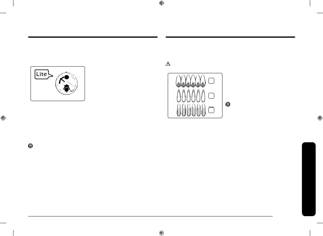
Step 8. Checking the flame quality
All combustion flames need to be visually checked to determine their flame quality.
CAUTION
If you attempt to measure the flame, please use caution. Burns could result.
1.Soft blue flames—Normal for natural gas
1operation.
2.Yellow tips on outer cones—Normal for LP gas operation.
3.Yellow flames—Abnormal for any gas operation; call for service.
NOTE
If burner flame looks like 3, the cooktop should not be used until it is serviced. Call for service. Normal burner flames shall look like 1 or 2, depending on the gas type you use.
English 19
instructions Installation
Install_NA30R5310FG_AA_DG68-01133A-00_EN.indd 19 |
|
|
2019-04-12 12:13:37 |
|
|
||
|
|
|
|
Installation instructions
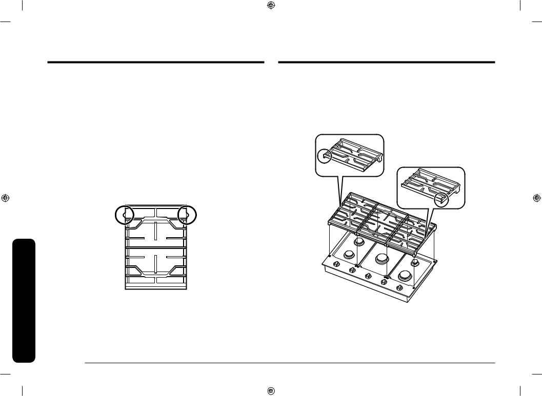
Step 9. Install the grates
36” Model : NA36R5310F*
 NOTE
NOTE
Install the grates as instructed below for longest life. When installed properly, the openings in the grates are centered over the burners.
The three cooktop grates are designed to fit in specific positions on the cooktop. For maximum stability, these grates should only be used in their proper positions.
•Place the left and right grates so that the thicker side of the right grate lines up with the right side of the cooktop and the thicker side of the left grate lines up with the left side of the cooktop.
•The center grate must be installed with the filled-in section, marked with the word ‘BACK’, oriented towards the back of the cooktop.
The center grate has two overhangs to help you locate the side grates correctly. It hits the side grates when you locate wrong direction. See the illustration below.
instructions Installation
20 English
To replace the grates correctly, follow these steps:
1.Orient the center grate as noted direction.
2.Gently lower the legs of the center grate so that leg dimples can match embosses on cooktop.
3.Locate thicker side of remaining two grates to face outside of cooktop
4.Gently lower the legs of two remaining grates into the corresponding embosses without interfering with center grate overhang.
Thicker side must be on the left
Thicker side must be on the right
Install_NA30R5310FG_AA_DG68-01133A-00_EN.indd 20 |
|
|
2019-04-12 12:13:37 |
|
|
||
|
|
|
|
30” Model : NA30R5310F*
NOTE
Install the grates as instructed below for longest life. When installed properly, the openings in the grates are centered over the burners.
The two cooktop grates are designed to fit in specific positions on the cooktop. For maximum stability, these grates should only be used in their proper positions.
•Place the grate with filled-in section on the right side to the left side, and the grate with filled-in section on the left side to the right side.
•Each grates must be installed with the filled-in section, marked ‘BACK’, oriented towards the back of the cooktop.
To replace the grates correctly, follow these steps:
1.Orient the center grate as noted direction.
2.Gently lower the legs of the Left grate so that leg dimples can match embosses on cooktop.
3.Locate filled-in section of right grate to face back side of the cooktop.
4.Gently lower the legs of right grate into the corresponding embosses without interfering with left grate overhang.
Filled-in section of
left grate Filled-in section of right grate
instructions Installation
English 21
Install_NA30R5310FG_AA_DG68-01133A-00_EN.indd 21 |
|
|
2019-04-12 12:13:37 |
|
|
||
|
|
|
|
Installation instructions
Step 10. Final installation checklist
 WARNING
• To ensure a safe and proper installation, the following checklist should be completed by the installer to ensure that no part of the installation has been overlooked.
•Proper installation is the responsibility of the homeowner. The importance of proper installation of your Samsung cooktop cannot be overemphasized.
You have just completed installing your cooktop. Make sure all control knobs are in the off position. The following is a checklist to confirm your cooktop is safely installed and ready for operation.
–Gas line has been properly connected to the cooktop. The gas has been turned on.
All connections have been checked for leaks.
–The cooktop is plugged into the properly grounded electrical receptacle.
–The cooktop burners and grates have been properly assembled.
–All burners have been tested for proper operation.
instructions Installation
22 English
LP (Propane) conversion instruction
 WARNING
•This conversion must be performed by a qualified installer or gas supplier in accordance with the manufacturer’s instructions and all codes and requirements of the authority having jurisdiction. Failure to follow ALL in structions could result in serious injury or property damage. The qualified agency performing this work assumes responsibility for the conversion.
•Know the location of the gas shut-off valve and how to shut it off if necessary.
•Unplug or disconnect power before servicing.
•Do not operate the cooktop burners when using LP gas before converting the pressure regulator and burner orifices for LP gas use. Failure to do so could cause high flames and toxic fumes which can result in serious injury.
•Do not mix up or substitute LP gas burner orifices during conversion process. Improper orifice placement will effect burner and cooking performance and could result in personal injury and/or product damage.
All Samsung gas cooktops are manufactured and shipped to be used with natural gas. The cooktop are also shipped with LP Conversion Kits, so the cooktop can be converted to be used with LP gas. The kits consist of a set of properly-sized
burner orifices to be used in the cooktop burners. These orifices will be positioned in a sheet of cardboard and placed in a plastic bag. The bag is placed with a user manual. The orifice in the pressure regulator is a dual-purpose orifice, one side for natural gas and the other for LP gas.
Install_NA30R5310FG_AA_DG68-01133A-00_EN.indd 22 |
|
|
2019-04-12 12:13:37 |
|
|
||
|
|
|
|

Supplied parts
The following parts make up the LP conversion kit:
NA30*5310F* |
NA36*5310F* |
The all orifices’ positions are marked on the provided sheet. The spud in the pressure regulator is factory-installed for Natural Gas (NG) use. LP conversion requires spud removal and reinstallation for LP use.
BURNER ORIFICE SIZES AND OUTPUT RATINGS
(LP Gas [Propane] 10 in WCP)
Burner Location |
BTU Rate |
Orifice size [mm] |
|
|
|
RF ¹ |
12500 |
1.06 |
|
|
|
RF ² |
11500 |
1.04 |
|
|
|
LF ¹ |
11500 |
1.04 |
|
|
|
LF ² |
8000 |
0.83 |
|
|
|
RR |
4500 |
0.62 |
|
|
|
LR |
8000 |
0.83 |
|
|
|
Center ² |
12500 |
1.06 |
|
|
|
1Model NA30*5310F*
2Model NA36*5310F*
BURNER ORIFICE SIZES AND OUTPUT RATINGS
(Natural Gas 5 in WCP)
Burner Location |
BTU Rate |
Orifice size [mm] |
|
|
|
RF ¹ |
17000 |
1.92 |
|
|
|
RF ² |
13000 |
1.64 |
|
|
|
LF ¹ |
13000 |
1.64 |
|
|
|
LF ² |
10000 |
1.4 |
|
|
|
RR |
5000 |
1.01 |
|
|
|
LR |
10000 |
1.4 |
|
|
|
Center ² |
17000 |
1.92 |
|
|
|
1Model NA30*5310F*
2Model NA36*5310F*
 NOTE
NOTE
Orifice markings:
115 – Denotes 1.15 mm orifice size opening.
instructions Installation
English 23
Install_NA30R5310FG_AA_DG68-01133A-00_EN.indd 23 |
|
|
2019-04-12 12:13:38 |
|
|
||
|
|
|
|

instructions Installation
Installation instructions
Required tools
Adjustable wrench |
1/2” open-end wrench |
Screwdrivers: Phillips |
Small flat-bladed |
Nut drivers: 9/32” or |
precision screwdriver |
7 mm |
To convert your for use with LP gas, perform the following steps and procedures:
1.Disconnect electrical power to the cooktop. Unplug the cooktop power cord, trip the circuit breaker, or remove the fuse from the fuse box.
2.Shut off the gas supply to the cooktop. Close the manual shut-off valve to the cooktop.
24 English
Converting the pressure regulator
 NOTE
NOTE
If you are using LP gas to fuel the cooktop, the following steps and conversions must be made before the flames can be adjusted.
1.Using your fingers, turn the cap. And carefully look at the spring retainer to locate the NAT or LP position.
LP |
Cap |
NAT |
|
|
Gasket |
NAT |
|
LP |
|
LP |
NAT |
Spring |
|
|
|||
|
Retainer |
||
|
|
||
NAT |
|
L.P./Propane |
|
LP |
Position |
||
NAT. Position |
|||
|
|
Pressure Regulator
2.Turn the spring retainer over by rotating it 90 deg., pull it from the cap, turn the spring retainer over so that LP is showing, insert it back into the cap, and then rotate it 90 deg. Into position.
3.Screw the cap back onto the regulator and tighten.
Install_NA30R5310FG_AA_DG68-01133A-00_EN.indd 24 |
|
|
2019-04-12 12:13:38 |
|
|
||
|
|
|
|

Converting the cooktop burners
 NOTE
NOTE
If you are using LP gas to fuel the cooktop, the following steps and conversions must be made before the flames can be adjusted.
1.Lift off the cooktop burner caps and the cooktop burner heads from the cooktop burner manifold cups.
Cap |
Cooktop Burner Locations |

 Burner Head


 Burner Cup
2.Using a 9/32” or 7 mm nut driver, remove the burner orifice from the bottom of each burner manifold cup.
Cooktop
Burner Orifice
NOTE
Save these orifices and note their positions for future conversions back to natural gas.
3.Locate the LP conversion orifices that were shipped with the cooktop.
4.Identify the proper orifice by orifice size for each of the cooktop burners.
5.Install the proper orifices in each of the burner manifold cups and tighten with a 9/32” or 7 mm nut driver.
NOTE
Any other placement of orifices could result in dangerous operating conditions and/or poor cooking results.
6.Set all burner heads on top of the manifold cups in the same location as they were removed. The hole on the side of the burner heads goes over the electrodes. The burner heads are correctly installed when they are flat on the top of the manifold cups.
7.Set all burner caps on top of the burner heads. These are also flat when they are installed to ensure proper safe operation.
instructions Installation
English 25
Install_NA30R5310FG_AA_DG68-01133A-00_EN.indd 25 |
|
|
2019-04-12 12:13:38 |
|
|
||
|
|
|
|

instructions Installation
Installation instructions
Adjusting low flame setting on cooktop burners
All Cooktop burner flames should be checked at their lowest setting. Use the following steps to check and adjust the cooktop burner settings.
 NOTES
NOTES
•Low setting adjustments should always be made with two or more burners operating at the same time.
•Call for service when you need to adjust the inner flame of the cooktop center burner settings.
1.Turn on two or more cooktop burners and set them between MED and HI.
2.Quickly turn one of the control knobs counterclockwise to the lowest setting. The flame should stay lit. If the flame flutters or goes out, adjust the bypass valve on the control valve for that burner.
3.Pull the control knob for that burner straight off.
Flat-bladed screwdriver
4.Using a small flat-bladed screwdriver, adjust the bypass valve screw in the base of the valve stem. Turn the bypass valve screw counter clockwise to increase the flame size.
Valve Stem
5.Replace control knob and recheck the low flame setting.
6.Repeat step 1 thru 5 to check and adjust the low flame settings on the remaining cooktop burners.
26 English
Combustion flame quality
1
2
3
Additional low flame check
1.Soft blue flames—Normal for natural gas operation.
2.Yellow tips on outer cones—Normal for LP gas operation.
3.Yellow flames—Abnormal for any gas operation. Further adjustment required.
1.Quickly open and close the cabinet door while the cooktop burner is set on LO. If the flame is extinguished, increase the low flame setting and repeat the test until the flame is stable.
2.Turn the knob from HI to the lowest setting quickly. If the flame goes out at the lowest setting, increase the low flame setting and repeat the test until the flame is stable.
 WARNING
1.Do not completely remove the valve set screw from the valve stem. The valve set screw is an integral part of the gas valve assembly. Removing the valve set screw will cause gas to leak.
2.After adjusting the valve set screw, inspect the assembly for gas leaks.
Install_NA30R5310FG_AA_DG68-01133A-00_EN.indd 26 |
|
|
2019-04-12 12:13:39 |
|
|
||
|
|
|
|
Loading...