


SERVICE MANUAL
ENGLISH

MYSONO U5 Service Manual
ENGLISH
Document No. CSD-SMEU5
Revision 00
Copyright 2010 by MEDISON CO., LTD

Safety Requirements
Classifications:
-Type of protection against electrical shock: Class I
-Degree of protection against electrical shock (Patient connection):Type BF equipment
-Degree of protection against harmful ingress of water: Ordinary equipment
-Degree of safety of application in the presence of a flammable anesthetic material with air or with oxygen or nitrous oxide: Equipment not suitable for use in the presence of a flammable anesthetic mixture with air or with oxygen or nitrous oxide.
-Mode of operation: Continuous operation
Electromechanical safety standards met:
-IEC/EN 60601-1 Medical Electrical Eqiupment, Part 1General Requirements for Safety.
-IEC/EN 60601-1-1 Safety requirements for medical electrical systems.
-IEC/EN 60601-1-2 Electromagnetic compatibility -Requirements and tests.
-IEC/EN 60601-2-37 Particular requirements for the safety of ultrasonic medical diagnostic and monitoring equipment.
-IEC 61157 Declaration of acoustic output parameters.
-ISO 10993-1 Biological evaluation of medical devices.
-UL 60601-1 Medical Electrical Equipment, Part 1 General Requirements for Safety.
-CSA 22.2, 601.1 Medical Electrical Equipment, Part 1 General Requirements for Safety.

Declarations;
This is CSA symbol for Canada and United States of America
This is manufacturer’s declaration of product compliance 0123 with applicable EEC directive(s) and the European notified
body.
This is manufacturer’s declaration of product compliance with applicable EEC directive(s).

READ THIS FIRST
Before asking for the product to be repaired, read this service manual thoroughly, learn how to troubleshoot, and make sure you understand the precautions fully.
The repair of the system and the replacement of parts must be carried out by an authorized dealer or the customer service department of MEDISON Co., Ltd.
The company is shall not be held liable for any injury and damage caused by not following this warning.
We are not responsible for errors that occur when the system is run on a user’s PC.
For safe use of this product, you should read ‘Chapter 2. Safety’ in this manual, prior to starting to useing this system.
DANGER
WARNING
CAUTION
NOTE
Describes precautions necessary to prevent user hazards of great urgency. Ignoring a DANGER warning will risk life-threatening injury.
Used to indicate the presence of a hazard that can cause serious personal injury, or substantial property damage.
Indicates the presence of a hazard that can cause equipment damage.
A piece of information useful for installing, operating and maintaining a system. Not related to any hazard.
If You Need Assistance
If you need any assistance with the equipment, please contact the MEDISON Customer Service Department or one of their worldwide customer service representatives, immediately.
`````Contents
Chapter 1. |
General Information |
1-1 |
|
1.1 |
Overview |
1-1 |
|
1.2 |
Features and Advantages of MySono U5 |
1-2 |
|
1.3 |
Product Configuration |
1-3 |
|
|
1.3.1 |
Console |
1-3 |
|
1.3.2 |
Probes |
1-4 |
|
1.3.3 |
MySono U5 Cart(Optional) |
1-4 |
1.4 |
Specifications |
1-5 |
|
Chapter 2. |
Safety |
|
2-1 |
2.1 |
Overview |
2-1 |
|
2.2 |
Safety – Related Information |
2-2 |
|
|
2.2.1 |
Safety Symbols |
2-2 |
|
2.2.2 |
Label |
2-4 |
2.3 |
Electrical Safety |
2-5 |
|
|
2.3.1 |
Prevention Electric Shock |
2-5 |
|
2.3.2 |
ESD |
2-6 |
|
2.3.3 |
EMI |
2-6 |
|
2.3.5 |
EMC |
2-7 |
2.4 |
Mechanical Safety |
2-13 |
|
|
2.4.1 |
Safety Note |
2-13 |
|
2.4.2 |
Moving the Equipment |
2-13 |
2.5 |
Biological Safety |
2-14 |
|
|
2.5.1 |
ALARA Principle |
2-14 |
2.6 |
Environmental Protection |
2-24 |
|
2.7 |
Battery Pack |
2-25 |
|
Contents
Contents
Chapter 3. Installing the Product |
3-1 |
||
3.1 |
Overview |
3-1 |
|
3.2 |
Transportation |
3-3 |
|
|
3.2.1 |
Precautions for Transportation |
3-3 |
|
3.2.2 |
Temperature and Humidity |
3-3 |
|
3.2.3 |
Transportation of the Product |
3-3 |
3.3 |
Unpacking |
3-4 |
|
|
3.3.1 |
Unpacking the Box |
3-4 |
|
3.3.2 |
Package Contents |
3-4 |
|
3.3.3 |
Checking Package Contents |
3-4 |
3.4 |
Precautions for Installation |
3-5 |
|
|
3.4.1 |
Precautions |
3-5 |
|
3.4.2 |
Installation Location |
3-5 |
3.5 |
Installation Procedure |
3-6 |
|
|
3.5.1 |
Installation Safety |
3-6 |
|
3.5.2 |
Connecting the AC Adapter |
3-6 |
|
3.5.3 |
Connecting the Probe |
3-7 |
3.6 |
Starting the Product |
3-8 |
|
3.7 |
Shutting down the Product |
3-9 |
|
|
3.7.1 |
Power Switch |
3-9 |
3.8 |
Connecting the Peripherals |
3-10 |
|
3.9 |
Battery Pack |
3-11 |
|
|
3.9.1 |
Battery Icon |
3-12 |
3.10 |
System Setting |
3-13 |
|
|
3.10.1 |
General System Setup |
3-13 |
|
3.10.2 |
Display Setup |
3-16 |
|
3.10.3 |
Peripherals Setup |
3-18 |
|
3.10.4 |
System Information |
3-19 |
|
3.10.5 |
DICOM Setup (Option) |
3-20 |
|
3.10.6 |
Utilities Setup |
3-30 |
|
3.10.7 |
Option Setup |
3-32 |
|
3.10.8 |
Auto Calc |
3-33 |
Contents

Contents
Chapter 4. Checking the Product |
4-1 |
||
4.1 |
Overview |
4-1 |
|
4.2 |
Starting the Product |
4-2 |
|
4.3 |
Monitor |
|
4-3 |
|
4.3.1 |
Monitor Display |
4-3 |
4.4 |
Control Panel |
4-5 |
|
|
4.4.1 |
Detail Control Panel |
4-5 |
|
4.4.2 |
Alphanumeric keyboard |
4-8 |
4.5 |
Checking the Performance |
4-10 |
|
|
4.5.1 |
Basic Check |
4-10 |
|
4.5.2 |
Detail Check |
4-10 |
Chapter 5. Product Structure |
5-1 |
||
5.1 |
Overview |
5-1 |
|
5.2 |
System Block Diagram |
5-3 |
|
5.3 |
Basic Structure of MySono U5 |
5-4 |
|
|
5.3.1 |
Overview |
5-4 |
|
5.3.2 |
Ultrasound System Part |
5-4 |
|
5.3.3 |
User Interface Part |
5-5 |
|
5.3.4 |
ETC. Part |
5-5 |
5.4 |
PSA |
|
5-6 |
5.5 |
Main Board |
5-8 |
|
5.6 |
Back End Part |
5-13 |
|
5.7 |
PCI Part |
|
5-16 |
5.8 |
Motor Control Panel |
5-17 |
|
5.9 |
PC Module |
5-18 |
|
5.10 |
Software DSC |
5-20 |
|
5.11 |
Control Panel |
5-21 |
|
5.12 |
Power Supply |
5-22 |
|
Contents

Contents
Chapter 6. |
Basic Maintenance |
6-1 |
|
6.1 |
Overview |
6-1 |
|
6.2 |
System Information |
6-2 |
|
6.3 |
Windows Mode |
6-3 |
|
6.4 |
Upgrade |
|
6-4 |
|
6.4.1 |
Software Upgrade |
6-4 |
|
6.4.2 |
Hardware Upgrade |
6-4 |
6.5 |
Admin Mode |
6-5 |
|
|
6.5.1 |
Entering Admin Mode |
6-5 |
|
6.5.2 |
Admin mode Functions |
6-6 |
6.6 |
Adding and Deleting Options |
6-11 |
|
|
6.6.1 |
Option type |
6-11 |
|
6.6.2 |
Registering Options |
6-12 |
|
6.6.3 |
Deleting Options |
6-15 |
Chapter 7. |
Troubleshooting |
7-1 |
|
7.1 |
Overview |
7-1 |
|
7.2 |
Power |
|
7-2 |
|
7.2.1 |
Power Failure |
7-2 |
|
7.2.2 |
Power cannot be turned off |
7-2 |
|
7.2.3 Power is automatically turned off |
7-2 |
|
7.3 |
Monitor |
|
7-3 |
|
7.3.1 |
Blank Screen |
7-3 |
|
7.3.2 Screen Color is Abnormal |
7-3 |
|
7.4 |
Error Messages |
7-4 |
|
|
7.4.1 |
System hangs after an error during booting |
7-4 |
|
7.4.2 |
System works even if error occurred |
7-4 |
7.5 |
Image |
|
7-5 |
|
7.5.1 |
No BW Image Echo and No BW Mode Format |
7-5 |
|
7.5.2 |
Noise Link Rain over the BW Mode Image (Noise) |
7-5 |
|
7.5.4 |
PW Doppler, Color Doppler and Motion Mode Trouble |
7-5 |
Contents
Contents
Chapter 8. Disassembly and Reassembly |
8-1 |
||
8.1 |
Overview |
8-1 |
|
8.2 |
Disassembly and Reassembly of a Basis |
8-3 |
|
|
8.2.1 |
Preparations |
8-3 |
|
8.2.2 HDD and Battery Pack |
8-3 |
|
|
8.2.3 |
Middle of System |
8-4 |
8.3 |
Disassembly and Reassembly of the Ultrasound System Part |
8-6 |
|
|
8.4.1 |
Preparations |
8-6 |
|
8.4.2 |
MAIN ASSY |
8-6 |
|
8.4.3 |
Sub Board |
8-7 |
8.4 |
Disassembly and Reassembly of the Control Panel |
8-8 |
|
|
8.4.1 |
Preparations |
8-8 |
|
8.4.2 |
Track Ball |
8-8 |
|
8.4.3 |
Control Panel |
8-9 |
|
8.4.4 Alpha numeric Keyboard and Speaker ASSY |
8-10 |
|
8.5 |
Disassembly and Reassembly of the LCD Part |
8-11 |
|
|
8.5.1 |
Preparations |
8-11 |
|
8.5.2 |
LCD Module |
8-13 |
Chapter 9. |
Probe |
9-1 |
9.1 |
Overview |
9-1 |
9.2 |
Probe List |
9-2 |
9.3 |
Thermal Index (TI Table) |
9-4 |
9.4 |
Ultrasound Transmission Gel |
9-5 |
9.5 |
Sheaths |
9-6 |
9.6 |
Probe Precautions |
9-7 |
9.7 |
Cleaning and Disinfecting the Probe |
9-9 |
Contents
Content
Chapter 10. |
User Maintenance |
10-1 |
|
10.1 |
Overview |
10-1 |
|
10.2 |
Operation Environment |
10-2 |
|
|
10.2.1 |
Installation Maintenance |
10-2 |
10.3 |
System Maintenance |
10-2 |
|
|
10.3.1 |
Cleaning |
10-3 |
|
10.3.2 |
Disinfections |
10-4 |
10.4 |
Battery Pack Maintenance |
10-5 |
|
|
10.4.1 Disconnection the Battery Pack |
10-5 |
|
|
10.4.2 Connection the Battery Pack |
10-5 |
|
|
10.4.3 |
Charging Battery Pack |
10-5 |
|
10.4.4 |
Stroring Battery Pack |
10-7 |
|
10.4.5 |
Discarding Battery Pack |
10-7 |
10.5 |
Administration of Information |
10-8 |
|
|
10.5.1 User Setting Back-up |
10-8 |
|
|
10.5.2 |
Patient Information Back-up |
10-8 |
|
10.5.3 |
Software |
10-8 |
Chapter 11. Service Part List |
11-1 |
|
11.1 |
Overview |
11-1 |
11.2 |
Cover |
11-2 |
11.3 |
System |
11-4 |
11.4 |
Control Panel |
11-6 |
11.5 |
LCD |
11-8 |
11.6 |
Mechanism and Chassis |
11-9 |
11.7 |
Option |
11-10 |
11.8 |
Probe |
11-11 |
Contents
1General Information
1.1Overview
Chapter 1 contains the information necessary to plan the Troubleshooting of MySono U5
The MySono U5 is a high-resolution color ultrasonographic image scanner with deep penetration which provides a variety of measurement functions.
Contents General Information
1.1 |
Overview |
1-1 |
|
1.2 |
Features and Advantages of MySono U5 |
1-2 |
|
1.3 |
Product Configuration |
1-3 |
|
|
1.3.1 |
Console |
1-3 |
|
1.3.2 |
Probes |
1-4 |
|
1.3.3 |
MySono U5 Cart(Optional) |
1-4 |
1.4 |
Specifications |
1-5 |
|
Chapter 1. General Information 1-1

1.2Features and Advantages of MySono U5
yDigital Beamforming : The MySono U5 incorporates Digital Beam Forming, the advanced proprietary technology provided by MEDISON.
yA variety of applications : The MySono U5 is designed for use in a variety of ultrasound applications including obstetrics, gynecology, abdominal, vascular, extremities, cardiac, urology and breast applications.
yVarious diagnostic Modes : 2D Mode, M Mode, Color Doppler Mode, Power Doppler Mode, PW Spectral Doppler Mode.
y3D imaging : More detailed 3D and 4D image can be acquired.
yMeasurement and Reporting – In addition to basic measurements such as distance, area, circumference and volume, the MySono U5 provides a variety of applicationspecific measurement functions. The resulting measurement data can be collated through its reporting function.
yReview of Scanned Images : The MySono U5 displays Cine images of 2621 frames and loop images of 4086 lines.
ySonoViewTM : An integrated ultrasound image management system, which allows you to archive, view and exchange image data.
yDigital Imaging and Communication in Medicine (DICOM) : A communication protocol, which allows you to archive, transfer and print images via a network..
yEasy Connection of Peripheral Devices - A variety of peripheral devices can be easily connected to the MySono U5.
Chapter 1. General Information 1-2
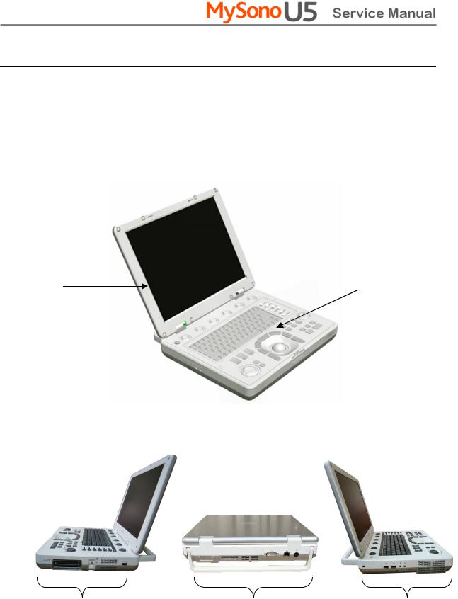
1.3Product Configuration
This Product consists of the cart(option), the console and the probes.
1.3.1Console
Whilst the inside of the console consists of devices enabling the implementation of ultrasound images, the outside of the console consists of various connection ports and handles.
LCD |
Control Panel |
[Figure 1-1] Console of MySono U5
Probe Lock Switch |
DVI-I Port |
Security Lock |
USB Port |
LAN Port |
MIC Port |
|
DC Power Port |
Audio Port |
|
|
USB Port |
[Figure 1-2] Rear and side of MySono U5
Chapter 1. General Information 1-3

1.3.2Probe
Probes are devices that generate ultrasound waves and process reflected wave data for the purpose of image formation.
NOTE For more information, refer to `Chapter 9 Probes’.
1.3.3MySono U5 Cart(Optional)
The MySono U5 System can be placed on a cart during use or for transport. For more information on installing and using the MySono U5 Cart, please refer to the installation guide that comes with it.
Chapter 1. General Information 1-4

1.4Specifications
|
|
|
|
Height: 70mm |
|
|
|
Physical Dimensions |
|
|
Width: 360mm |
|
|
|
|
|
Depth: 291mm |
|
|
|
|
|
|
|
|
|
|
|
|
|
|
Weight: more than 5.4kg (without battery) |
|
|
|
|
|
|
|
|
|
|
|
|
|
Hight: 23mm |
|
|
|
Battery Pack |
|
Width: 214.6mm |
|
||
|
|
Depth: 59mm |
|
|||
|
|
|
|
|
||
|
|
|
|
Weight: less than 400g |
|
|
|
|
|
|
|
||
|
Monitor |
|
|
15 inch LCD monitor |
|
|
|
|
|
|
|
|
|
|
Probe connections |
|
One probe port |
|
||
|
|
|
|
|
|
|
|
|
|
|
Curved Linear Array : C3-7 |
|
|
|
|
|
|
Linear Array : L5-12 |
|
|
|
Probes |
|
|
Phased Array : P2-4 |
|
|
|
|
|
|
|||
|
|
|
|
Endocavity Curved Linear Array : EV4-9 |
|
|
|
|
|
|
Volume Probe : 3D2-6 |
|
|
|
|
|
|
|
|
|
|
Electrical Parameters |
|
Input:100~240VAC, 0.7~1.63A, 47~63Hz |
|
||
|
|
Output:19VDC, 7.9A, 150W Max |
|
|||
|
|
|
|
|
||
|
|
|
|
|
|
|
|
Pressure Limits |
|
|
Operating: 700hPa to 1060hPa |
|
|
|
|
|
Storage: 700hPa to 1060hPa |
|
|
|
|
|
|
|
|
|
|
|
|
|
|
|
|
|
|
Humidity Limits |
|
Operating: 30% to 75% |
|
||
|
|
Storage & Shipping: 20% to 90% |
|
|||
|
|
|
|
|
||
|
|
|
|
|
|
|
|
Temperature Limits |
|
|
Operating: 10OC ~ 35OC |
|
|
|
|
|
Storage & Shipping: -25OC ~ 60OC |
|
|
|
|
|
|
|
|
|
|
|
|
|
|
|
|
|
|
|
|
|
Chapter 1. General Information 1-5 |
||

|
|
|
Video (DVI-I) port |
|
Input / Output |
|
Network port |
|
|
USB port |
|
|
Connections |
|
|
|
|
Microphone port |
|
|
|
|
|
|
|
|
Audio port |
|
|
|
|
|
|
|
Video (DVI-I) port |
|
|
|
Network port |
|
Auxiliary |
|
USB port |
|
|
|
Microphone port |
|
|
|
Audio port |
|
|
|
|
|
Application |
|
Abdomen, Obstetrics, Gynecology, Musculoskeletal, Small Parts, |
|
|
Vascular, Cardiac, Pediatric Cardiology, TCD, Urology |
|
|
|
|
|
|
|
|
|
|
|
|
2D imaging mode |
|
|
|
M imaging mode |
|
|
|
Color Doppler Imaging (CDI) mode |
|
|
|
Power Doppler Imaging (PDI) mode |
|
|
|
Directional Power Doppler Imaging (DPDI) mode |
|
|
|
Power Pulse Inversion Imaging (PPII) mode |
|
|
|
Pulse Wave (PW) Spectral Doppler imaging mode |
|
Imaging modes |
|
Tissue Doppler Imaging (TDI) mode |
|
|
|
Tissue Doppler Wave mode |
|
|
|
3D imaging mode |
|
|
|
4D imaging mode |
|
|
|
Dual modes |
|
|
|
Combined modes |
|
|
|
Simultaneous mode |
|
|
|
Zoom |
|
|
|
|
|
|
|
Transmit focusing, maximum of eight points (four points simultaneously |
|
Focusing |
|
selectable) |
|
|
|
Digital dynamic receive focusing (continuous) |
|
|
|
|
Chapter 1. General Information 1-6

|
Gray Scale |
|
|
256 (8 bits) |
|
|
|
|
|
|
|
|
|
|
|
Obstetrics, Gynecology, Cardiac, Carotid, Urology, Fetal Echo, LE Artery, UE |
|
|
Measurement Packages |
|
Artery, LE Vein, UE Vein, Radiology, TCD, Thyroid, Breast, Testicle, |
||
|
|
Superficial, Pediatric Hips, MSK |
|||
|
|
|
|
||
|
|
|
|
* Refer the Chapter 5 for additional information |
|
|
|
|
|
|
|
|
|
|
|
Obstetrics, Gynecology, Cardiology, Carotid, Fetal Echo, UE Artery, |
|
|
Measurement |
|
|
LE Artery, UE Vein, LE Vein, Radiology, TCD, Thyroid, Breast, |
|
|
|
|
Testicle, Superficial, Pediatric Hips, MSK |
|
|
|
|
|
|
|
|
|
|
|
|
* Refer the Chapter 5 for additional information |
|
|
|
|
|
|
|
|
|
|
|
Maximum 2,621 frames for CINE memory |
|
|
Image Storage |
|
Maximum 4,086 Lines for LOOP memory |
||
|
|
|
|
Image filing system |
|
|
|
|
|
|
|
|
|
|
|
TGC control |
|
|
|
|
|
Mode-independent gain control |
|
|
|
|
|
Acoustic power control (adjustable) |
|
|
Signal processing |
|
|
Dynamic aperture |
|
|
(Pre-processing) |
|
|
Dynamic apodization |
|
|
|
|
Dynamic range control (adjustable) |
|
|
|
|
|
|
|
|
|
|
|
|
Image view area control |
|
|
|
|
|
M-mode sweep speed control |
|
|
|
|
|
|
|
|
|
|
|
Frame average |
|
|
|
|
|
Edge Enhancement / Blurring |
|
|
Signal processing |
|
Gamma-scale windowing |
||
|
(Post-processing) |
|
Image orientation (left/right and up/down, rotation) |
||
|
|
|
|
White on black/black on white |
|
|
|
|
|
Zoom |
|
|
|
|
|
|
|
Chapter 1. General Information 1-7
2Safety
2.1Overview
Chapter 2 contains the information necessary to Safety
Please read this chapter before using the MEDISON ultrasound system. It relates to the ultrasound system, the probes, the recording devices, and the optional equipment.
MySono U5 is intended for use by or by the order of, and under the supervision of a licensed physician who is directly qualified to use the medical device.
Contents |
|
|
|
2.1 |
Overview |
2-1 |
|
2.2 |
Safety – Related Information |
2-2 |
|
|
2.2.1 |
Safety Symbols |
2-2 |
|
2.2.2 |
Label |
2-4 |
2.3 |
Electrical Safety |
2-5 |
|
|
2.3.1 |
Prevention Electric Shock |
2-5 |
|
2.3.2 |
ESD |
2-6 |
|
2.3.3 |
EMI |
2-6 |
|
2.3.4 |
EMC |
2-7 |
2.4 |
Mechanical Safety |
2-13 |
|
|
2.4.1 |
Safety Note |
2-13 |
|
2.4.2 |
Moving Equipment |
2-13 |
2.5 |
Biological Safety |
2-14 |
|
|
2.5.1 |
ALARA Principle |
2-14 |
2.6 |
Environmental Protection |
2-24 |
|
2.7 |
Battery Pack |
2-25 |
|
Chapter 2. Safety 2-1

2.2Safety - Related Information
2.2.1Safety Symbols
The International Electro Technical Commission (IEC) has established a set of symbols for medical electronic equipment, which classifies a connection or warn of potential hazards. The classifications and symbols are shown below.
Symbols |
Description |
|
|
|
DC (direct current) voltage source |
|
|
|
Isolated patient connection (Type BF applied part). |
|
|
|
Power switch (Supplies/cuts the power for product) |
|
|
|
Indicates a caution for risk of electric shock. |
|
|
|
Indicates dangerous voltages over 1000V AC or over |
|
1500V DC. |
|
|
|
Isolated patient connection (Type BF applied part). |
|
|
|
Power switch (Supplies/cuts the power for product) |
|
|
|
Electrostatic discharge |
|
|
|
Data Output port |
|
|
|
Data Input port |
|
|
|
Data Input/Output port |
|
|
|
Left and right Audio / Video input |
|
|
Chapter 2. Safety 2-2
Symbols |
Description |
|
|
|
Left and right Audio / Video output |
|
|
|
Print remote output |
|
|
|
Foot switch connector |
|
|
|
ECG connector |
|
|
|
USB connector |
|
|
|
Microphone connector |
|
|
|
Audio port |
|
|
|
Protection against the effects of immersion. |
|
|
|
Protection against dripping water. |
|
|
|
Probe port |
|
|
|
Network port |
|
|
Chapter 2. Safety 2-3
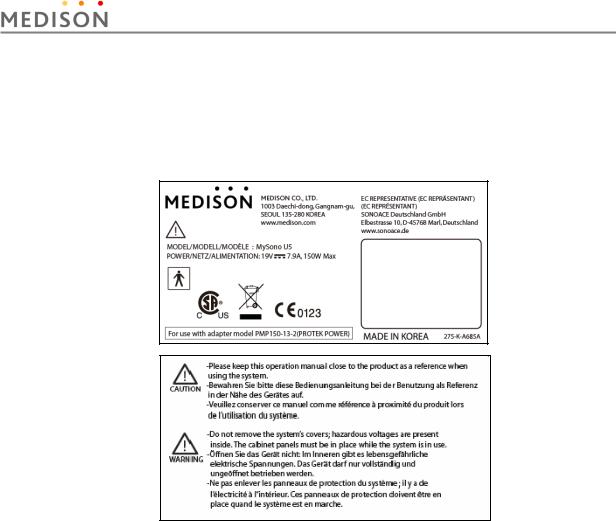
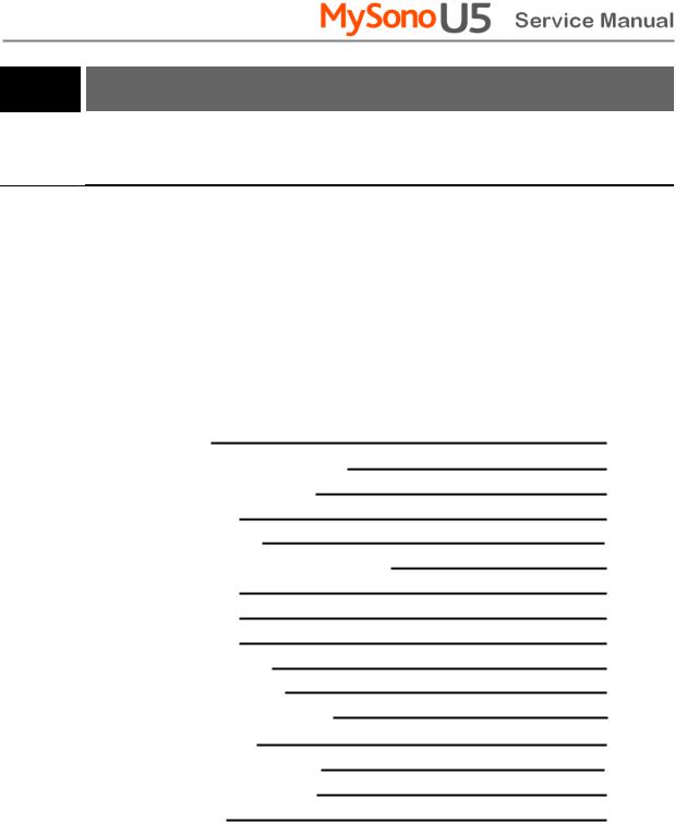
2.2.2Labels
To protect the system, you may see ‘Warning’ or ‘Caution’ marked on the surface of the product
[Figure 2-1] Marked on the bottom of the product
Chapter 2. Safety 2-4
2.3Electrical Safety
This equipment has been verified as a Class I device with Type BF applied parts.
CAUTION y As for US requirement, the LEAKAGE CURRENT might be measured from a center-tapped circuit when the equipment connects in the United States to 240V supply system.
yTo help assure grounding reliability, connect to a “hospital grade” or “hospital only” grounded power outlet.
2.3.1Prevention of Electric Shock
WARNING y There is a risk of electric shock if the externally mounted recording and monitoring devices are not properly grounded.
yNever open the product housing cover. There is high voltage power within the product. All internal adjustments and replacements must be made by the MEDISON Customer Service.
yAlways check the product housing, cables, cords, plugs, etc. before use. Do not use the product if the surface is cracked, chipped, or split, the housing is damaged, or the cable is abraded.
yAlways disconnect the system from the wall outlet prior to cleaning the system.
yAll patient contact devices, such as probes, must be removed from the patient prior to application of a high voltage defibrillation pulse.
yNever use the product in proximity to any flammable anesthetic gases(N2O) or oxidizing gases. There is a risk of explosion.
yBe sure only to use an AC adaptor that is recommended by MEDISON.
CAUTION y An isolation transformer protects the system from power surges. The isolation transformer continues to operate when the system is in standby.
yDo not immerse the cable in liquids. Cables are not waterproof.
yDo not touch SIP/SOP and the patient simultaneously. There is a risk of electric shock from leakage current.
Chapter 2. Safety 2-5

Additional equipment connected to medical electrical equipment must comply with the respective IEC or ISO standards (e.g. IEC 60950 for data processing equipment). Furthermore all configurations shall comply with the requirements for medical electrical systems (see IEC 60601-1-1 or clause 16 of the 3 Ed. of IEC 60601-1, respectively). Anybody connecting additional equipment to medical electrical equipment configures a medical system and is therefore responsible that the system complies with the requirements for medical electrical systems. Attention is drawn to the fact that local laws take priority over the above-mentioned requirements. If in doubt, consult your local representative or the technical service department.
2.3.2ESD
Electrostatic discharge (ESD), commonly referred to as a static shock, is a naturally occurring phenomenon. ESD is most prevalent during conditions of low humidity, which can be caused by heating or air conditioning. During low humidity conditions, electrical charges naturally build up on individuals, creating static electricity. An ESD occurs when an individual with an electrical energy build-up comes in contact with conductive objects such as metal doorknobs, file cabinets, computer equipment, and even other individuals. The static shock or ESD is a discharge of the electrical energy build-up from a charged individual to a lesser or non-charged individual or object.
The ESD caution symbol is on the probe connector and the rear panel.
CAUTION y |
The level of electrical energy discharged from a system user or patient |
|
to an ultrasound system can be significant enough to cause damage to |
|
the system or probes. |
yAlways perform the pre-ESD preventive procedures before using connectors marked with the ESD warning label.
-Apply anti-static spray on carpets or linoleum.
-Use anti-static mats.
-Ground the product to the patient table or bed.
yIt is highly recommended that the user be given training on ESDrelated warning symbols and preventive procedures.
2.3.3EMI
Although this system has been manufactured in compliance with existing EMI (Electromagnetic Interference) requirements, use of this system in the presence of an electromagnetic field can cause momentary degradation of the ultrasound image.
If this occurs often, MEDISON suggests a review of the environment in which the system is being used, to identify possible sources of radiated emissions. These emissions could be from other electrical devices used within the same room or an adjacent room.
Chapter 2. Safety 2-6

Communication devices such as cellular phones and pagers can cause these emissions. The existence of radios, TVs, or microwave transmission equipment nearby can also cause interference.
CAUTION In cases where EMI is causing disturbances, it may be necessary to relocate this system.
2.3.4EMC
The testing for EMC(Electromagnetic Compatibility) of this system has been performed according to the international standard for EMC with medical devices (IEC60601-1-2). This IEC standard was adopted in Europe as the European norm (EN60601-1-2).
2.3.4.1Guidance and manufacturer’s declaration - electromagnetic emission
This product is intended for use in the electromagnetic environment specified below. The customer or the user of this product should assure that it is used in such an environment.
|
Emission test |
|
Compliance |
|
Electromagnetic environment -guidance |
|
|
|
|
|
|
|
RF Emission |
|
Group 1 |
|
The Ultrasound System uses RF energy only |
|
(Radiation) |
|
|
for its internal function. Therefore, its RF |
|
|
|
Class B |
|
||
|
CISPR 11 |
|
|
emissions are very low and are not likely to |
|
|
|
|
|
||
|
RF Emission |
|
Group 1 |
|
cause any interference in nearby electronic |
|
(Radiation) |
|
|
equipment. |
|
|
|
Class B |
|
||
|
CISPR 11 |
|
|
The Ultrasound System is suitable for use in all |
|
|
|
|
|
||
|
Harmonic Emission |
|
Class A |
|
establishments, including domestic |
|
IEC 61000-3-2 |
|
|
establishments and those directly connected to |
|
|
|
|
|
||
|
|
|
|
|
the public low-voltage power supply network |
|
Flicker Emission |
|
|
|
|
|
|
Complies |
|
that supplies building used for domestic |
|
|
IEC 61000-3-3 |
|
|
||
|
|
|
|
purpose. |
|
|
|
|
|
|
Chapter 2. Safety 2-7

2.3.4.2Approved Cables, Transducers and Accessories for EMC
1) Approved Cable for Electromagnetic Compliance
Cables connected to this product may affect its emissions; Use only the cable types and lengths listed below table.
Cable |
Type |
Length |
|
|
|
DVI |
Shielded |
Normal |
USB |
Shielded |
Normal |
LAN(RJ45) |
Twisted pair |
Any |
MIC |
Unshielded |
Any |
Printer Remote |
Unshielded |
Any |
Audio R.L |
Shielded |
Normal |
2)Probe
The transducers listed in Chapter 9. ‘Probes’ when used with this product, have been tested to comply with Group 1 Class B emission as required by International Standard CISPR
3)Approved Accessories for Electromagnetic Compliance
Accessories used with this product may effect its emissions.
CAUTION When connecting other customer-supplied accessories to the system, such as a remote printer or VCR, it is the user’s responsibility to ensure the electromagnetic compatibility of the system. Use only CISPR 11 or CISPR 22, CLASS B compliant devices.
WARNING Use of unapproved cables, probes or accessories may increase the electromagnetic emission or decrease the durability of the ultrasound product..
Chapter 2. Safety 2-8

|
Immunity test |
|
|
|
IEC 60601 |
|
|
Compliance level |
|
Electromagnetic environment - |
|
|
|
|
|
Test level |
|
|
|
guidance |
|||
|
|
|
|
|
|
|
|
|
|
||
|
|
|
|
|
|
|
|
|
|
|
|
|
|
|
|
|
|
|
|
|
|
|
|
|
Electrostatic |
|
|
|
|
|
|
|
|
Floors should be wood, concrete |
|
|
discharge (ESD) |
|
±6KV Contact |
|
±6KV |
Contact |
or ceramic tile. If floors are |
||||
|
|
|
covered with synthetic material, |
||||||||
|
|
|
|
|
|
|
|
|
|
|
|
|
IEC 61000-4-2 |
|
±8KV |
air |
|
±8KV |
air |
the relative humidity should be at |
|||
|
|
|
|
|
least 30%. |
||||||
|
|
|
|
|
|
|
|
|
|
|
|
|
Electrical fast |
|
±2KV |
for power supply |
|
±2KV for power |
Mains power quality should be that |
||||
|
|
|
|
|
of a typical commercial or hospital |
||||||
|
transient/burst |
|
lines |
|
|
|
supply lines |
||||
|
|
|
|
|
environment. |
||||||
|
|
|
|
±1KV for input/output |
|
±1KV for input/ |
|||||
|
|
|
|
|
|
||||||
|
IEC 61000-4-4 |
|
lines |
|
|
|
output lines |
|
|||
|
|
|
|
|
|
|
|
|
|
||
|
|
|
|
|
|
|
|
|
|
|
|
|
Surge |
|
±1KV differential mode |
|
±1KV differential mode |
Mains power quality should be that |
|||||
|
IEC 61000-4-5 |
|
|
||||||||
|
|
±2KV common mode |
|
±2KV common mode |
of a typical commercial or hospital |
||||||
|
|
|
|
|
environment. |
||||||
|
|
|
|
|
|
|
|
|
|
|
|
|
|
|
|
|
|
|
|||||
|
Voltage dips, short |
|
<5% Uт |
|
<5% Uт |
Mains power quality should be that |
|||||
|
interruptions and |
|
(>95% dip in Uт) |
|
(>95% dip in Uт) |
of a typical commercial or hospital |
|||||
|
voltage variations |
|
for 0.5cycle |
|
for 0.5cycle |
environment. If the user of this |
|||||
|
on power supply |
|
|
|
|
|
|
|
|
product requires continued |
|
|
input lines |
|
40% Uт |
|
40% Uт |
operation during power mains |
|||||
|
IEC 61000-4-11 |
|
(60% dip in Uт ) |
|
(60% dip in Uт ) |
interruptions, it is recommended |
|||||
|
|
for 5 cycle |
|
for 5 cycle |
that this product be powered from |
||||||
|
|
|
|
70% Uт |
|
70% Uт |
an uninterruptible power supply or |
||||
|
|
|
|
|
a battery. |
||||||
|
|
|
|
(30% dip in Uт) |
|
(30% dip in Uт) |
|
||||
|
|
|
|
for 25 cycle |
|
for 25 cycle |
|
||||
|
|
|
|
<5% Uт |
|
<5% Uт |
|
||||
|
|
|
|
(<95% dip in Uт ) |
|
(<95% dip in Uт ) |
|
||||
|
|
|
|
for 5 s |
|
|
|
for 5 s |
|
|
|
|
Power frequency |
|
|
|
|
|
|
|
|
Power frequency magnetic fields |
|
|
(50/60Hz) |
|
|
|
|
|
|
|
|
should be at levels characteristic |
|
|
magnetic field |
|
3 A/m |
|
|
|
3 A/m |
|
|
of a typical location in a typical |
|
|
|
|
|
|
|
|
|
|
|
|
commercial or hospital |
|
IEC 61000-4-8 |
|
|
|
|
|
|
|
|
environment. |
|
NOTE Uт is the a.c. mains voltage prior to application of the test level.
Chapter 2. Safety 2-9
Conducted RF |
3 Vrms |
0.01V |
Portable and mobile RF communications |
IEC 61000-4-6 |
150 kHz to 80MHz |
|
equipment should be used no closer to any part |
|
of the Ultrasound System, including cables, |
||
|
|
|
|
|
|
|
than the recommended separation distance |
|
|
|
calculated from the equation applicable to the |
|
|
|
frequency of the transmitter. |
|
|
|
Recommended separation distance |
|
|
|
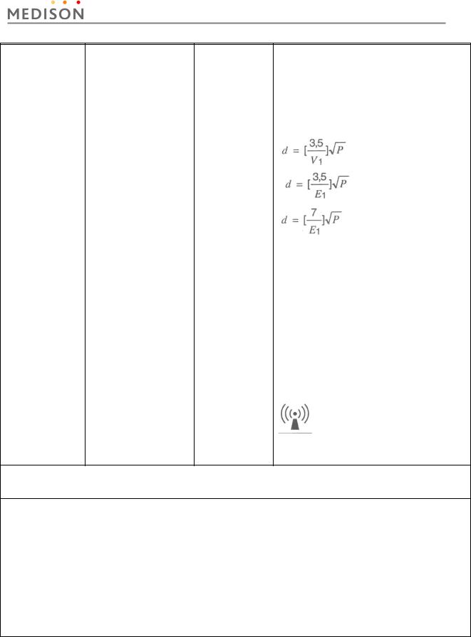
80MHz to 800MHZ |
|
|
|
800MHz to 2.5GHz |
Radiated RF |
3 V/m |
3 V/m |
Where P is the maximum output power rating of |
IEC 61000-4-3 |
80 MHz to 2.5GHz |
|
the transmitter in watts (W) according to the |
|
transmitter manufacturer and d is the |
||
|
|
|
|
|
|
|
recommended separation distance in meters |
|
|
|
(m). |
|
|
|
Field strengths from fixed RF transmitters, as |
|
|
|
deter-mined by an electromagnetic site survey, a |
|
|
|
should be less than the compliance level in |
|
|
|
each frequency range. b |
|
|
|
Interference may occur in the vicinity of |
|
|
|
equipment marked with the following symbol : |
NOTE 1) At 80MHz and 800MHz, the higher frequency range applies.
NOTE 2) These guidelines may not apply in all situations. Electromagnetic propagation is affected by absorption and reflection from structures, objects and people.
a Field strengths from fixed transmitters, such as base stations for radio (cellular/cordless) telephones and land mobile radios, amateur radio, AM and FM radio broadcast and TV broadcast cannot be predicted theoretically with accuracy. To assess the electromagnetic environment due to fixed RF transmitters, an electromagnetic site survey should be considered. If the measured field strength in the location in which the Ultrasound System is used exceeds the applicable RF compliance level above, the Ultrasound System should be observed to verify normal operation. If abnormal performance is observed, additional measures may be necessary, such as re-orienting or relocating the Ultrasound System or using a shielded location with a higher RF shielding effectiveness and filter attenuation.
b Over the frequency range 150kHz to 80MHz, field strengths should be less than [V1] V/m.
Chapter 2. Safety 2-10
2.3.4.3Recommended separation distances between portable and mobile RF communications equipment and the ACCUVIX V20
This product is intended for use in an electromagnetic environment in which radiated RF disturbances are controlled. The customer or the user of this product can help Prevent electromagnetic interference by maintaining a minimum distance between portable and mobile RF communications equipment (transmitters) and this product as recommended below, according to the maximum output power of the communications equipment.
|
Separation distance according to frequency of transmitter [m] |
||
|
|
80MHz to 800MHz |
|
Rated maximum |
150kHz to 80MHz |
800MHz to 2.5GHz |
|
output power of |
|
|
|
transmitter [W] |
|
|
|
|
|
|
|
|
V1=0.01Vrms |
E1=3 V/m |
E1=3V/m |
|
|
|
|
|
|
|
|
0.01 |
35.00 |
0.11 |
0.23 |
0.1 |
110.68 |
0.36 |
0.73 |
1 |
350.00 |
1.16 |
2.33 |
10 |
1106.80 |
3.68 |
7.37 |
100 |
3500.00 |
11.66 |
23.33 |
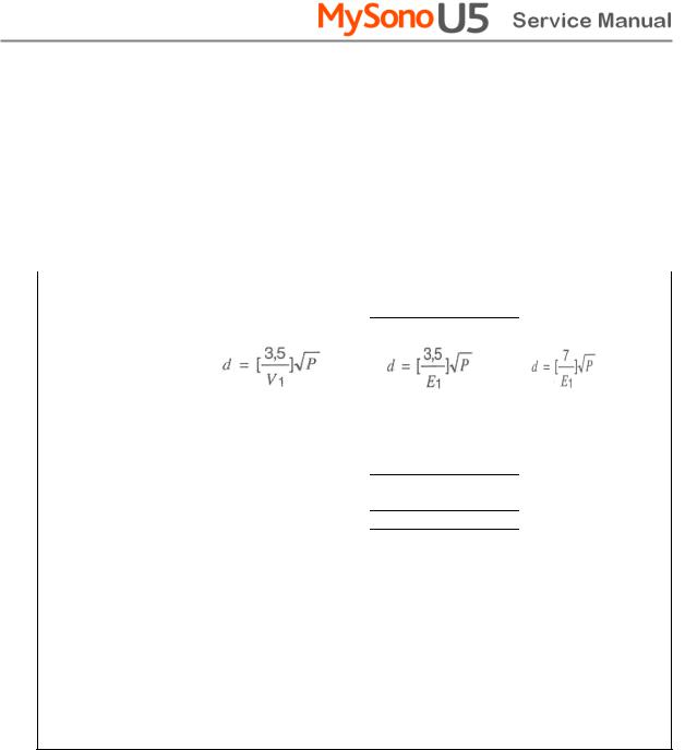
For transmitters rated at a maximum output power not listed above, the recommended separation distance d in meters (m) can be estimated using the equation applicable to the frequency of the transmitter, where p is the maximum output power rating of the transmitter in watts (W) according to the transmitter manufacturer.
NOTE 1) At 80MHz and 800MHz, the separation distance for the higher frequency range applies.
NOTE 2) These guidelines may not apply in all situations. Electromagnetic propagation is affected by absorption and reflection from structures, objects and people.
2.3.4.4Electromagnetic environment – guidance
The Ultrasound System must be used only in a shielded location with a minimum RF shielding effectiveness and, for each cable that enters the shielded location. Field strengths outside the shielded location from fixed RF transmitters, as determined by an electromagnetic site survey, should be less than 3V/m.
It is essential that the actual shielding effectiveness and filter attenuation of the shielded location be verified to assure that they meet the minimum specification.
Chapter 2. Safety 2-11

If the system is connected to other customer-supplied equipment, such as a CAUTION local area network (LAN) or a remote printer, Medison cannot guarantee that
the remote equipment will work correctly in the presence of electromagnetic phenomena.
2.3.4.5Avoiding Electromagnetic Interference
A medical device can either generate or receive electromagnetic interference. The EMC standards describe tests for both emitted and received interference. Medison Ultrasound System does not generate interference in excess of the referenced standards.
An Ultrasound System is designed to receive signals at radio frequency and is therefore susceptible to interference generated by RF energy sources. Examples of other source of interference are medical device, information technology products, and radio and television transmission towers. Tracing the source of radiated interference can be a difficult task. Customers should consider the following in an attempt to locate the source:
-Is the interference intermittent or constant?
-Does the interference show up only with one transducers operating at the same frequency or with several transducer?
-Do two different transducer operating at the same frequency have the same problem?
-Is the interference present if the system is moved to a different location in the facility?
The answers to these questions will help determine if the problem reside with the system or the scanning environment. After you answer the question, contact your local MEDISON customer service department.
Chapter 2. Safety 2-12
 Loading...