


Service Manual

WARRANTY
Samsung Medison provides the following warranty to the purchaser of this unit.This warranty is valid for a period of one year from the date of installation and covers all problems caused by faulty workmanship or faulty material. Samsung Medison will, as sole and exclusive remedy and at no charge, replace any such defective unit returned to Samsung Medison within the designated warranty period.
The warranty does not cover damages and loss caused by outside factors including, but not limited to, re,ood, storm, tidal wave, lightning, earthquake, theft, abnormal conditions of operation, and intentional destruction of the equipment. Damage caused by equipment relocation is not covered.
The warranty is void in cases where the equipment has been damaged as a result of an accident, misuse, abuse, dropping, or when attempts to modify or alter any part or assembly of the equipment have taken place.
Parts with cosmetic defects or deterioration will not be replaced. Replacement of batteries, training materials, and supplies are not covered.
Samsung Medison will not be responsible for incidental or consequential damages of any kind arising from or connected with the use of the equipment.
Samsung Medison will not be responsible for any loss, damage, or injury resulting from a delay in services rendered under the warranty
This limited warranty is in lieu of all other warranties expressed or implied, including warranties of merchant ability or tness for any particular use. No representative or other person is authorized to represent or assume for Samsung Medison any warranty liability beyond that set forth herein.
Defective equipment shipped from you to Samsung Medison must be packed in the replacement cartons. Shipping and insurance costs are the responsibility of the customer. To return defective material to Samsung Medison contact the Samsung Medison Customer Service Department.
Samsung Medison or a local distributor will make available, upon request, circuit diagrams, a component parts list, descriptions, calibration instructions and other information which will assist your appropriately quali ed technical personnel to repair those parts of the equipment which are designed by Samsung Medison as repairable.
CAUTION: United State federal law restricts this device to sale by or on the order of physicians.
MANUFACTURER : SAMSUNG MEDISON CO., LTD.
Samsung Medison Bldg., 42, Teheran-ro 108-gil, Gangnam-Gu, Seoul,135-280 Korea
SAMSUNG MEDISON CO., LTD. Customer Service Department
TEL : 82-2-2194-1234 FAX : 82-2-2194-1071
Website: www.samsungmedison.com
EC REPRESENTATIVE
SONOACE Deutschland GmbH Elbestrasse 10, 45768 Marl, Germany
TEL : 49-2365-924-3810 FAX : 49-2365-924-3830

Service Manual
Version 1.00.00
English
CSD-SMDU6

 Safety Classi cations
Classifications:
XXType of protection against electrical shock: Class I
XXDegree of protection against electrical shock (Patient connection):Type BF equipment
XXDegree of protection against harmful ingress of water: Ordinary equipment
XXDegree of safety of application in the presence of a flammable anesthetic material with air or with oxygen or nitrous oxide: Equipment not suitable for use in the presence of a flammable anesthetic mixture with air or with oxygen or nitrous oxide.
XXMode of operation: Continuous operation
Electromechanical safety standards met:
XXIEC/EN 60601-1 Medical Electrical Equipment, Part 1General Requirements for Safety.
XXIEC/EN 60601-1-1 Safety requirements for medical electrical systems.
XXIEC/EN 60601-1-2 Electromagnetic compatibility -Requirements and tests.
XXIEC/EN 60601-2-37 Particular requirements for the safety of ultrasonic medical diagnostic and monitoring equipment.
XXIEC 61157 Declaration of acoustic output parameters.
XXISO 10993-1 Biological evaluation of medical devices.
XXUL 60601-1 Medical Electrical Equipment, Part 1 General Requirements for Safety.
XXCSA 22.2, 601.1 Medical Electrical Equipment, Part 1 General Requirements for Safety.

Declarations
This is CSA symbol for Canada and United States of America
This is manufacturer’s declaration of product compliance with applicable EEC directive(s) and the European notified body.
This is manufacturer’s declaration of product compliance with applicable EEC directive(s).
This is GMP symbol for Good Manufacturing Practice of Korea quality system regulation.
Certificate of Excellent Service Quality is to certify that the above company has served customers with excellent services by the Ministry of Knowledge Economy Republic of Korea.


 Before Using This Product
Read this service manual to familiarize yourself thoroughly with repair procedures and important safety information before attempting to service the product.
Failure to follow this information may cause an accident such as electric shock, as well as mechanical or other hazards to the service engineer, product operator, and/or patient.
1.Refer to the service manual when you service the product.
2.You are strongly urged to familiarize yourself with the operational safety information contained in ‘Chapter 2 Safety’.
3.This product is an ultrasound diagnosis device and cannot be used from the user’s PC. We are not responsible for errors that occur when the system is run on the user’s PC.
4.This product may only be serviced by the Global Service Group of Samsung Medison or an authorized engineer.
5.Samsung Medison is not responsible for any problems caused by an unauthorized person servicing the product.
6.The manufacturer is not responsible for any damage to this product caused by user carelessness and/or neglect.
7.The content of this manual may be changed without prior notice.
8.The following terms are used to highlight safety precautions that the user must be aware of:
DANGER: Disregarding this instruction may result in death, serious injury, or other dangerous situations.
WARNING: Follow this information to prevent a serious accident or damage to property.
CAUTION: Hazards or unsafe practices that may result in minor personal injury or property damage.
NOTE: The accompanying information covers an installation, operation, or maintenance procedure that requires careful attention from the user, but has little chance of leading directly to a dangerous situation.
If You Need Help
If you need help regarding the product, please contact the Samsung Medison Global Service Group in charge of servicing this product.


 Revision History
The revision history of this manual is as the follows.
Document No. |
Date |
REASON FOR CHANGE |
|
|
|
CSD-SMDU6 |
2011-12-28 |
Initial Release |
|
|
|
Table of Contents
Table of Contents
Chapter 1 Introduction |
|
||
1.1 |
Overview............................................................................................................................................... |
1-3 |
|
1.2 |
Main Features of MySono U6........................................................................................................ |
1-4 |
|
1.3 |
Product Con guration..................................................................................................................... |
1-5 |
|
|
1.3.1 |
Console............................................................................................................................................................ |
1-5 |
|
1.3.2 |
Probes............................................................................................................................................................... |
1-6 |
|
1.3.3 |
Dedicated Cart (Optional) ........................................................................................................................ |
1-6 |
1.4 |
Product Speci cations..................................................................................................................... |
1-7 |
|
Chapter 2 |
Safety |
|
||
2.1 |
Overview............................................................................................................................................... |
|
2-3 |
|
2.2 |
Safety Information ............................................................................................................................ |
2-4 |
||
|
2.2.1 |
Safety Symbols.............................................................................................................................................. |
2-4 |
|
|
2.2.2 |
Location of Labels........................................................................................................................................ |
2-5 |
|
2.3 |
Electrical Safety .................................................................................................................................. |
2-6 |
||
|
2.3.1 Prevention of Electric Shock.................................................................................................................... |
2-6 |
||
|
2.3.2 |
ESD .................................................................................................................................................................... |
|
2-7 |
|
2.3.3 |
EMI...................................................................................................... |
............................................................... |
2-7 |
|
2.3.4 |
EMC ................................................................................................................................................................... |
|
2-8 |
2.4 |
Mechanical Safety .......................................................................................................................... |
2-14 |
||
|
2.4.1 |
Safety Notes................................................................................................................................................. |
2-14 |
|
|
2.4.2 |
Moving the Equipment ........................................................................................................................... |
2-14 |
|
2.5 |
Biological Safety.............................................................................................................................. |
2-15 |
||
|
2.5.1 |
ALARA Principle.......................................................................................................................................... |
2-15 |
|
2.6 |
Protecting the Environment....................................................................................................... |
2-30 |
||
2.7 |
Battery................................................................................................................................................. |
|
2-31 |
|
11


 Service Manual
Chapter 3 |
Installing the Product |
|
||
3.1 |
Overview............................................................................................................................................... |
|
3-3 |
|
3.2 |
Transporting........................................................................................................................................ |
3-4 |
||
|
3.7.1 |
Caution on Transporting........................................................................................................................... |
3-4 |
|
|
3.7.2 |
Humidity and Temperature...................................................................................................................... |
3-4 |
|
3.3 |
Unpacking............................................................................................................................................ |
|
3-5 |
|
|
3.7.3 |
Dismantling the Product Box .................................................................................................................. |
3-5 |
|
|
3.7.4 |
Product Components................................................................................................................................. |
3-5 |
|
|
3.7.5 |
MySono U6 Cart (sold separately) ......................................................................................................... |
3-6 |
|
|
3.7.6 |
MySono U6 Cart (Optional), 2 Probe Connector.............................................................................. |
3-7 |
|
3.4 |
Installation Environment ................................................................................................................ |
3-8 |
||
|
3.7.7 |
Caution............................................................................................................................................................. |
3-8 |
|
3.5 |
Installing the Product....................................................................................................................... |
3-9 |
||
|
3.7.8 |
Installation Safety ........................................................................................................................................ |
3-9 |
|
|
3.7.9 |
AC Adapter Connection ............................................................................................................................ |
3-9 |
|
|
3.7.10 |
Probe Connection...................................................................................................................................... |
3-10 |
|
3.6 |
Turning the Product On .............................................................................................................. |
3-11 |
||
3.7 |
Shutting Down the Product ....................................................................................................... |
3-12 |
||
3.8 |
Connecting Peripherals................................................................................................................ |
3-13 |
||
3.9 |
Connecting the Battery................................................................................................................ |
3-14 |
||
|
3.7.11 |
Battery Icons ................................................................................................................................................ |
3-15 |
|
3.10 |
System Settings............................................................................................................................... |
3-16 |
||
|
3.7.12 |
General System Settings (Setup-General)........................................................................................ |
3-16 |
|
|
3.7.13 |
Display ........................................................................................................................................................... |
3-19 |
|
|
3.7.14 |
Annotate ....................................................................................................................................................... |
3-23 |
|
|
3.7.15 |
Peripherals.................................................................................................................................................... |
3-25 |
|
|
3.7.16 |
User De ned Key........................................................................................................................................ |
3-27 |
|
|
3.7.17 |
Miscellaneous.............................................................................................................................................. |
3-28 |
|
|
3.7.18 |
Option ............................................................................................................................................................ |
3-29 |
|
|
3.7.19 |
DICOM............................................................................................................................................................ |
3-30 |
|
|
3.7.20 |
Auto Calc....................................................................................................................................................... |
3-43 |
|
|
3.7.21 |
About.............................................................................................................................................................. |
3-44 |
|
12

Table of Contents
Chapter 4 Inspecting the Product |
|
||
4.1 |
Overview............................................................................................................................................... |
4-3 |
|
4.2 |
Turning On the Product .................................................................................................................. |
4-4 |
|
4.3 |
Monitor.................................................................................................................................................. |
4-5 |
|
|
4.3.1 |
Screen Layout................................................................................................................................................ |
4-5 |
|
4.3.2 |
Screen Brightness Adjustment ............................................................................................................... |
4-6 |
4.4 |
Control Panel....................................................................................................................................... |
4-7 |
|
|
4.4.1 Functions of the Control Panel ............................................................................................................... |
4-7 |
|
|
4.4.2 |
Alphanumeric Keyboard......................................................................................................................... |
4-10 |
4.5 |
Inspecting Functions..................................................................................................................... |
4-11 |
|
|
4.5.1 |
Basic Inspections........................................................................................................................................ |
4-11 |
|
4.5.2 |
Detailed Inspections................................................................................................................................. |
4-12 |
Chapter 5 |
Product Structure |
|
|
5.1 |
Overview |
............................................................................................................................................... |
5-3 |
5.2 |
System Block .....................................................................................................................Diagram |
5-4 |
|
|
5.2.1 |
System ........................................................................................................................................ Overview |
5-4 |
5.3 |
Basic Structure ......................................................................................................of MySono U6 |
5-5 |
|
|
5.3.1 |
Overview ......................................................................................................................................................... |
5-5 |
|
5.3.2 |
Ultrasound ............................................................................................................................. System Part |
5-6 |
|
5.3.3 |
User ........................................................ ............................................................................... Interface Part |
5-7 |
|
5.3.4 |
Miscellaneous ....................................................................................................................................... Part |
5-7 |
5.4 |
PSA |
|
5-8 |
|
5.4.1 |
Main ............................................................................................................................................. Functions |
5-8 |
|
5.4.2 |
Speci .................................................................................................................................................. cation |
5-8 |
|
5.4.3 ..................................................Operational Principles of the High Voltage Switching Process |
5-9 |
|
5.5 |
Main ........................................................................................................................................Board |
5-10 |
|
|
5.5.1 ........................................................................................................................................... |
Main Functions |
5-10 |
|
5.5.2 ........................................................................................................................................ |
Beamformer Part |
5-11 |
|
5.5.3 .......................................................................................................................................................... |
CW Part |
5-14 |
|
5.5.4 ............................................................................................................................................... |
Back End Part |
5-17 |
13


 Service Manual
5.6 |
PCI Part ............................................................................................................................................... |
5-21 |
|
|
5.6.1 |
Main Functions ........................................................................................................................................... |
5-21 |
5.7 |
Motor Control Part ......................................................................................................................... |
5-22 |
|
|
5.7.1 |
Main Functions ........................................................................................................................................... |
5-22 |
|
5.7.2 |
Block Diagram............................................................................................................................................. |
5-22 |
|
5.7.3 |
Speci cation ................................................................................................................................................ |
5-22 |
|
5.7.4 |
Operational Principles.............................................................................................................................. |
5-23 |
5.8 |
PC Module......................................................................................................................................... |
5-24 |
|
|
5.8.1 |
Main Functions ........................................................................................................................................... |
5-24 |
5.9 |
Software DSC ................................................................................................................................... |
5-25 |
|
|
5.9.1 |
Main Functions ........................................................................................................................................... |
5-25 |
|
5.9.2 |
Operational Principles.............................................................................................................................. |
5-25 |
5.10 |
Control Panel.................................................................................................................................... |
5-26 |
|
|
5.10.1 |
Main Functions ........................................................................................................................................... |
5-26 |
5.11 |
Power Supply ................................................................................................................................... |
5-27 |
|
|
5.11.1 |
Power adapter............................................................................................................................................. |
5-27 |
|
5.11.2 |
DC to DC Power Module ......................................................................................................................... |
5-27 |
Chapter 6 Basic Maintenance
6.1 |
Overview............................................................................................................................................... |
6-3 |
|
6.2 |
System Information .......................................................................................................................... |
6-4 |
|
6.3 |
Windows Mode .................................................................................................................................. |
6-5 |
|
6.4 |
Version Updates................................................................................................................................. |
6-6 |
|
|
6.4.1 |
Software Version Updates ........................................................................................................................ |
6-6 |
|
6.4.2 |
Hardware Version Updates....................................................................................................................... |
6-6 |
6.5 |
Admin Mode........................................................................................................................................ |
6-7 |
|
|
6.5.1 |
Entering Admin Mode................................................................................................................................ |
6-7 |
|
6.5.2 |
Admin Mode Functions............................................................................................................................. |
6-8 |
6.6 |
Adding and Deleting Options ................................................................................................... |
6-13 |
|
|
6.6.1 |
Types of Option .......................................................................................................................................... |
6-13 |
|
6.6.2 |
Adding an Option...................................................................................................................................... |
6-14 |
|
6.6.3 |
Removing an Option ................................................................................................................................ |
6-17 |
14

Table of Contents
Chapter 7 |
Troubleshooting |
|
||
7.1 |
Overview |
............................................................................................................................................... |
7-3 |
|
7.2 |
Power |
..................................................................................................................................................... |
|
7-4 |
|
7.2.1 Power ................................................................................................................................Fails to Turn On |
7-4 |
||
|
7.2.2 Power ...............................................................................................................................Fails to Turn O |
7-4 |
||
|
7.2.3 ............................................................................................................. |
Power Turns O Spontaneously |
7-5 |
|
7.3 |
Monitor.................................................................................................................................................. |
|
7-6 |
|
|
7.3.1 .............................................................................................................Nothing is Displayed on Screen |
7-6 |
||
|
7.3.2 .................................................................................................................................... |
Screen is Discolored |
7-6 |
|
7.4 |
Error Messages.................................................................................................................................... |
7-7 |
||
|
7.4.1 ................................................................................Error Occurs and Product Stops while Booting |
7-7 |
||
|
7.4.2 .............................................................................................................Error Occurs but Product Works |
7-7 |
||
7.5 |
Image ..................................................................................................................................................... |
|
|
7-8 |
|
7.5.1 ...............................................................No BW Mode Image Echo; No BW Mode Image Format |
7-8 |
||
|
7.5.2 ................................................................................Rain-like Streaking in BW Mode Image (Noise) |
7-8 |
||
|
7.5.3 .................PW Doppler Mode, CW Doppler Mode, Color Doppler Mode, M Mode Trouble |
7-8 |
||
Chapter 8 |
Disassembly and Reassembly |
|
||
8.1 |
Overview |
............................................................................................................................................... |
8-3 |
|
8.2 |
Basic Disassembly and Reassembly ........................................................................................... |
8-4 |
||
|
8.2.1 |
Preparation..................................................................................................................................................... |
8-4 |
|
|
8.2.2 HDD .....................................................................................................................................& Battery Pack |
8-4 |
||
|
8.2.3 Middle .............................................................................of System Disassembly and Reassembly |
8-5 |
||
8.3 |
Ultrasound ......................................................System Part Disassembly and Reassembly |
8-7 |
||
|
8.3.1 |
Preparation..................................................................................................................................................... |
8-7 |
|
|
8.3.2 |
MAIN .....................................................................................................................................................ASSY |
8-7 |
|
|
8.3.3 Sub ...........................................................................................Board Disassembly and Reassembly |
8-8 |
||
8.4 |
Control Panel ..........................................................................Disassembly and Reassembly |
8-9 |
||
|
8.4.1 |
Preparation..................................................................................................................................................... |
8-9 |
|
|
8.4.2 |
Trackball .......................................................................................................................................................... |
8-9 |
|
|
8.4.3 |
Control ..................................................................................................................................Panel Board |
8-10 |
|
|
8.4.4 Alpha .......................................................................................numeric Keyboard & Speaker ASSY |
8-11 |
||
8.5 |
LCD Part Disassembly .................................................................................and Reassembly |
8-12 |
||
|
8.5.1 |
Preparation................................................................................................................................................... |
8-12 |
|
|
8.5.2 |
LCD ..................................................................................................................................................Module |
8-12 |
|
15


 Service Manual
Chapter 9 |
Probes |
|
||
9.1 |
Overview............................................................................................................................................... |
|
9-3 |
|
9.2 |
Probe List .............................................................................................................................................. |
|
9-4 |
|
|
9.2.1 Probe Application and Preset.................................................................................................................. |
9-4 |
||
|
9.2.2 |
Function list.................................................................................................................................................... |
9-5 |
|
9.3 |
Thermal Index (TI) Table.................................................................................................................. |
9-9 |
||
9.4 |
Ultrasound transmission Gel...................................................................................................... |
9-10 |
||
9.5 |
Sheaths............................................................................................................................................... |
|
9-11 |
|
|
9.5.1 |
Applying Sheath......................................................................................................................................... |
9-11 |
|
9.6 |
Probe Safety Precautions............................................................................................................. |
9-12 |
||
|
9.6.1 Use and Infection Control of the Probe............................................................................................. |
9-12 |
||
|
9.6.2 |
Electric Shocks ............................................................................................................................................ |
9-13 |
|
9.7 |
Cleaning and Disinfecting the Probe...................................................................................... |
9-14 |
||
|
9.7.1 Information on Detergent, Disinfectant, and Ultrasound Gel.................................................. |
9-14 |
||
|
9.7.2 |
Cleaning ........................................................................................................................................................ |
9-21 |
|
|
9.7.3 |
Disinfection .................................................................................................................................................. |
9-22 |
|
Chapter 10 Maintenance
10.1 |
Overview............................................................................................................................................ |
10-3 |
|
10.2 |
Operational Environment............................................................................................................ |
10-4 |
|
|
10.2.1 Installing and Storing the Product...................................................................................................... |
10-4 |
|
10.3 |
Product Maintenance ................................................................................................................... |
10-5 |
|
|
10.3.1 |
Cleaning ........................................................................................................................................................ |
10-5 |
|
10.3.2 |
Disinfection .................................................................................................................................................. |
10-6 |
|
10.3.3 |
Accuracy Check........................................................................................................................................... |
10-6 |
10.4 |
Battery Pack Management.......................................................................................................... |
10-7 |
|
|
10.4.1 |
Battery Pack Removal............................................................................................................................... |
10-7 |
|
10.4.2 |
Battery Pack Installation.......................................................................................................................... |
10-7 |
|
10.4.3 Recharging the Battery Pack ................................................................................................................. |
10-8 |
|
|
10.4.4 Storing the Battery Pack.......................................................................................................................... |
10-9 |
|
|
10.4.5 Disposing of the Battery Pack ............................................................................................................... |
10-9 |
|
16

Table of Contents
10.5 Information Maintenance ......................................................................................................... |
10-10 |
|
10.5.1 |
User Setting Back-up ............................................................................................................................. |
10-10 |
10.5.2 |
Patient Information Restore................................................................................................................ |
10-10 |
10.5.3 |
Software ..................................................................................................................................................... |
10-11 |
Chapter 11 Service Part List
11.1 |
Overview............................................................................................................................................ |
11-3 |
11.2 |
Cover ................................................................................................................................................... |
11-4 |
11.3 |
System................................................................................................................................................. |
11-5 |
11.4 |
Control Panel.................................................................................................................................... |
11-7 |
11.5 |
LCD....................................................................................................................................................... |
11-8 |
11.6 |
Mechanism & Chassis.................................................................................................................... |
11-9 |
11.7 |
Option............................................................................................................................................... |
11-10 |
11.8 |
Probe ................................................................................................................................................. |
11-11 |
17

Chapter 1 Introduction
1.1 |
Overview........................................................ |
1-3 |
|
1.2 |
Main Features of MySono U6.................... |
1-4 |
|
1.3 |
Product Configuration................................ |
1-5 |
|
|
1.3.1 |
Console....................................................................... |
1-5 |
|
1.3.2 |
Probes......................................................................... |
1-6 |
|
1.3.3 |
Dedicated Cart (Optional)................................... |
1-6 |
1.4 |
Product Specifications................................ |
1-7 |
|
Chapter 1 Introduction
1.1 Overview
Chapter 1 describes important information about MySono U6 that you must know before servicing the product. The product’s main features, configuration, and specification are explained.
MySono U6 is a high-resolution, deep-penetration color diagnostic ultrasound system that offers a wide variety of convenient exam options.
1-3


 Service Manual
1.2 Main Features of MySono U6
XXCutting-edge Digital Beamforming technology: Utilizes proprietary technology developed by Samsung Medison.
XXDiverse applications: Can be used for such diverse applications as general, obstetrics, gynecology, abdomen, vascular, extremities, cardiac, urology, and chest
XXDiverse diagnosis modes: Features an array of diagnosis modes including 2D mode, M mode, Color Doppler mode (C mode), Power Doppler mode (PD mode), and PW Spectral Doppler mode (D mode).
XX3D image feature: Provides detailed three-dimensional images in 3D and 4D Image modes.
XXMeasurement and report features: In addition to measurements of distance, area, circumference, and volume, various measurement features for each application are provided. A report feature for utilizing the measurements is also provided.
XXScan image review feature: Up to 2621-frame Cine images and 4086-line Loop images are provided.
XXSONOVIEW feature: An integrated image management system facilitates storage and accessing of images and ensures compatibility of data.
XXDigital Imaging and Communication in Medicine (DICOM) feature: Save, transfer, or print images over the network.
XXEase of connecting peripherals: Various peripherals can be connected and used with ease.
1-4
Chapter 1 Introduction
1.3 Product Configuration
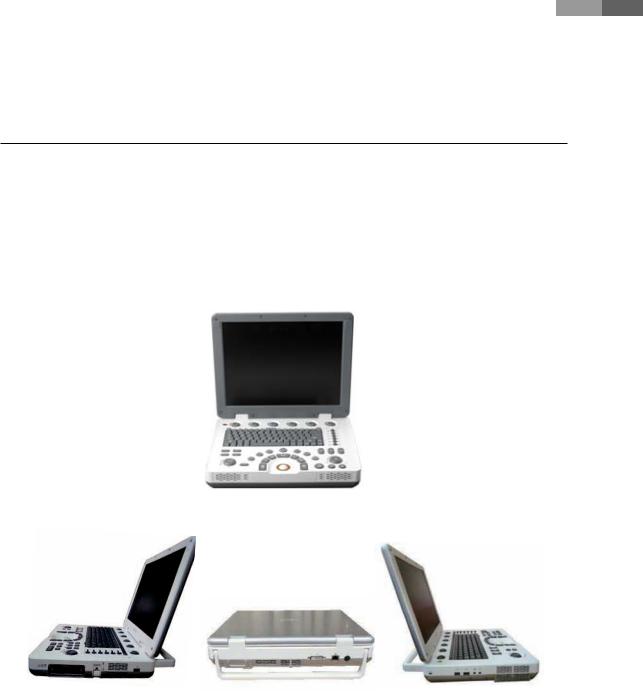
MySono U6 consists of the main console, probes, and an optional cart.
1.3.1 Console
The inside of the console contains ultrasound imaging components, and the outside features various connectors and a handle.
[Figure 1.1 MySono U6 Console]
Probe Connector |
DVI-I Port |
Security |
USB Port |
LAN Port |
MIC Port |
|
DC Power Port |
Audio Port |
|
|
USB Port |
|
[Figure 1.2 MySono U6 Side View] |
|
1-5


 Service Manual
1.3.2 Probes
Probes are devices that generate ultrasound waves and then process the reflected wave data to form images.
NOTE: For detailed information, refer to ‘Chapter 9. Probes’.
1.3.3 Dedicated Cart (Optional)
The MySono U6 cart can be used as a base station for your MySono U6, or to move it around. For more information on using and setting up the MySono U6 Cart, refer to the accompanying manual.
[Figure 1.3 MySono U6 Cart]
1-6

Chapter 1 Introduction
1.4 Product Specifications
|
Height: 75.4mm |
|
Physical Dimensions |
Width: 360mm |
|
Depth: 291mm |
||
|
||
|
Weight: more than 4.8kg (without battery) |
|
|
|
|
|
Hight: 23.5mm |
|
Battery Pack |
Width: 224.5mm |
|
Depth: 78.5mm |
||
|
||
|
Weight: less than 700g |
|
|
|
|
Monitor |
15 inch LCD monitor |
|
|
|
|
Probe connections |
One probe port |
|
Two probe ports for option |
||
|
||
|
|
|
|
Curved Linear Array: C2-5, C2-8, C4-9 |
|
|
Linear Array: LN5-12 |
|
Probes |
Phased Array: P2-4 |
|
(Type BF / IPX7) |
Endocavity Curved Linear Array: EVN4-9 |
|
|
Volume Probe: 3DC2-6, 3D4-9 |
|
|
CW Probe: CW2.0 |
|
|
|
|
Electrical Parameters |
Input: 100-240VAC, 0.7-1.63A, 47-63Hz |
|
Output: 19VDC, 7.9A, 150W Max |
||
|
||
|
|
|
Pressure Limits |
Operating: 700hPa - 1060hPa |
|
Storage: 700hPa - 1060hPa |
||
|
||
|
|
|
Humidity Limits |
Operating: 30% - 75% |
|
Storage & Shipping: 20% - 90% |
||
|
||
|
|
|
Temperature Limits |
Operating: 10°C - 35°C |
|
Storage & Shipping: -25°C - 60°C |
||
|
||
|
|
|
|
Video (DVI-I) port |
|
Input / Output |
Network port |
|
USB port |
||
Connections |
||
Microphone port |
||
|
||
|
Audio port |
|
|
|
|
|
USB ECG |
|
|
USB Foot Switch(IPX1) |
|
|
External DVD Multi |
|
Auxiliary |
USB Video Printer |
|
|
USB Laser Printer |
|
|
USB Hard Disk Drive |
|
|
USB Flash Memory Media |
|
|
|
|
Application |
Abdomen, Obstetrics, Gynecology, Musculoskeletal, Small Parts, Vascular, Cardiac, |
|
Pediatric Cardiology, TCD, Urology |
||
|
||
|
|
1-7


 Service Manual
|
2D imaging mode |
|
|
M imaging mode |
|
|
Color Doppler Imaging (CDI) mode |
|
|
Power Doppler Imaging (PDI) mode |
|
|
Directional Power Doppler Imaging (DPDI) mode |
|
|
Power Pulse Inversion Imaging (PPII) mode |
|
|
Pulse Wave (PW) Spectral Doppler imaging mode |
|
Imaging modes |
Tissue Doppler Imaging (TDI) mode |
|
|
Tissue Doppler Wave mode |
|
|
3D imaging mode |
|
|
4D imaging mode |
|
|
Dual modes |
|
|
Combined modes |
|
|
Simultaneous mode |
|
|
Zoom mode |
|
|
|
|
|
Transmit focusing, maximum of eight points (four points simultaneously |
|
Focusing |
selectable) |
|
|
Digital dynamic receive focusing (continuous) |
|
|
|
|
Gray Scale |
256 (8 bits) |
|
|
|
|
|
Obstetrics, Gynecology, Cardiac, Carotid, Urology, Fetal Echo, LE Artery, UE Artery, |
|
Measurement Packages |
LE Vein, UE Vein, Radiology, TCD, Thyroid, Breast, Testicle, Superficial, Pediatric |
|
Hips, MSK |
||
|
||
|
* Refer to the Chapter 5 for additional information. |
|
|
|
|
|
Trackball operation of multiple cursors |
|
|
2D mode: Linear measurements and area measurements using elliptical |
|
Measurement |
approximation or trace |
|
|
M mode: Continuous readout of distance, time and slope rate |
|
|
Doppler mode: Velocity and trace |
|
|
|
|
|
Maximum 2,621 frames for CINE memory |
|
Image Storage |
Maximum 8,192 Lines for LOOP memory |
|
|
Image filing system |
|
|
|
|
|
TGC control |
|
|
Mode-independent gain control |
|
|
Acoustic power control (adjustable) |
|
Signal processing |
Dynamic aperture |
|
(Pre-processing) |
Dynamic apodization |
|
|
Dynamic range control (adjustable) |
|
|
Image view area control |
|
|
M-mode sweep speed control |
|
|
|
|
|
Frame average |
|
|
Edge Enhancement / Blurring |
|
Signal processing |
Gamma-scale windowing |
|
(Post-processing) |
Image orientation (left/right and up/down, rotation) |
|
|
White on black/black on white |
|
|
Zoom |
|
|
|
1-8

Chapter 2 |
Safety |
|
2.1 |
Overview........................................................ |
2-3 |
|
2.2 |
Safety Information....................................... |
2-4 |
|
|
2.2.1 |
Safety Symbols........................................................ |
2-4 |
|
2.2.2 |
Location of Labels.................................................. |
2-5 |
2.3 |
Electrical Safety............................................ |
2-6 |
|
|
2.3.1 Prevention of Electric Shock............................... |
2-6 |
|
|
2.3.2 |
ESD............................................................................... |
2-7 |
|
2.3.3 |
EMI................................................................................ |
2-7 |
|
2.3.4 |
EMC.............................................................................. |
2-8 |
2.4 |
Mechanical Safety...................................... |
2-14 |
|
|
2.4.1 |
Safety Notes............................................................ |
2-14 |
|
2.4.2 |
Moving the Equipment...................................... |
2-14 |
2.5 |
Biological Safety......................................... |
2-15 |
|
|
2.5.1 |
ALARA Principle..................................................... |
2-15 |
2.6 |
Protecting the Environment.................... |
2-30 |
|
2.7 |
Battery.......................................................... |
2-31 |
|

Chapter 2 Safety
2.1 Overview
Chapter 2 contains important information for servicing MySono U6 safely.
It is relevant to the ultrasound system, the probes, the recording devices, and any of the optional equipment.
MySono U6 is intended for use by, or by the order of, and under the supervision of, a licensed physician who is qualified for direct use of the medical device.
This equipment should not be used by any healthcare professional or individual who is not properly qualified to operate it. Prolonged use of three-dimensional ultrasound (3D, 4D) by an unqualified individual, such as to produce a commemorative photograph or video of the fetus, may have an adverse effect on the fetus.
Be sure to use the three-dimensional ultrasound diagnostic imaging system only for its intended purposes, since using it for purposes other than diagnosing the fetus may have an adverse effect on the fetus.
2-3


 Service Manual
2.2 Safety Information
2.2.1 Safety Symbols
The International Electro Technical Commission (IEC) has established a set of symbols for medical electronic equipment, which classify a connection or warn of potential hazards. The classifications and symbols are shown below.
Symbol |
Description |
Symbol |
Description |
|||||||||||||||
|
|
|
|
|
|
|
|
|
|
|
|
|
|
|
|
|
|
|
|
|
|
|
|
|
|
|
|
|
DC (direct current) voltage source |
|
|
|
|
|
|
|
Left and right Audio / Video |
|
|
|
|
|
|
|
|
|
|
|
|
|
|
|
|
|
output |
|
|
|
|
|
|
|
|
|
|
|
|
|
|
|
|
|
|
|
|
|
|
|
|
|
|
|
|
|
|
|
|
|
|
|
|
|
|
|
|
|
|
|
|
|
|
|
|
|
Isolated patient connection (Type |
|
|
|
|
|
|
|
Remote print output |
|
|
|
|
|
|
|
|
|
|
|
|
|
|
|
|
|
||
|
|
|
|
|
|
|
|
|
|
BF applied part) |
|
|
|
|
|
|
|
|
|
|
|
|
|
|
|
|
|
|
|
|
|
|
|
|
|
|
|
|
|
|
|
|
|
|
|
|
|
|
|
|
|
|
|
|
|
|
|
|
|
|
|
|
|
|
|
|
Power switch (Supplies/cuts the |
|
|
|
|
|
|
|
Foot switch connector |
|
|
|
|
|
|
|
|
|
|
|
|
|
|
|
|
|
||
|
|
|
|
|
|
|
|
|
|
power for product) |
|
|
|
|
|
|
|
|
|
|
|
|
|
|
|
|
|
|
|
|
|
|
|
|
|
|
|
|
|
|
|
|
|
|
|
|
|
|
|
|
|
|
|
|
|
|
|
|
|
|
|
|
|
|
|
|
Caution: Electric shock risk, |
|
|
|
|
|
|
|
ECG connector |
|
|
|
|
|
|
|
|
|
|
electricity |
|
|
|
|
|
|
|
|
|
|
|
|
|
|
|
|
|
|
|
|
|
|
|
|
|
|
|
|
|
|
|
|
|
|
|
|
|
|
|
|
|
|
|
|
|
|
|
|
|
|
|
|
|
|
|
|
Indicates dangerous voltages |
|
|
|
|
|
|
|
USB connector |
|
|
|
|
|
|
|
|
|
|
over 1,000V AC or over 1,500V DC. |
|
|
|
|
|
|
|
|
|
|
|
|
|
|
|
|
|
|
|
|
|
|
|
|
|
|
|
|
|
|
|
|
|
|
|
|
|
|
|
|
|
|
|
|
|
|
|
|
|
|
|
|
|
|
|
|
Danger, warning, caution |
|
|
|
|
|
|
|
MIC input port |
|
|
|
|
|
|
|
|
|
|
|
|
|
|
|
|
|
|
|
|
|
|
|
|
|
|
|
|
|
Protective grounding terminal |
|
|
|
|
|
|
|
Audio Port |
|
|
|
|
|
|
|
|
|
|
|
|
|
|
|
|
|
||
|
|
|
|
|
|
|
|
|
|
|
|
|
|
|
|
|
|
|
|
|
|
|
|
|
|
|
|
|
|
|
|
|
|
|
|
|
|
|
|
|
|
|
|
|
|
|
|
|
|
|
|
|
|
|
|
|
|
|
|
|
|
|
|
|
|
|
ESD (electrostatic discharge) |
|
|
|
|
|
|
|
Protection against the effects of |
|
|
|
|
|
|
|
|
|
|
warning |
|
|
|
|
|
|
|
immersion |
|
|
|
|
|
|
|
|
|
|
|
|
|
|
|
|
|
||
|
|
|
|
|
|
|
|
|
|
|
|
|
|
|
|
|
|
|
|
|
|
|
|
|
|
|
|
|
DATA output port |
|
|
|
|
|
|
|
Protection against dripping |
|
|
|
|
|
|
|
|
|
|
|
|
|
|
|
|
|
water |
|
|
|
|
|
|
|
|
|
|
|
|
|
|
|
|
|
|
|
|
|
|
|
|
|
|
|
|
|
|
|
|
|
|
|
|
|
|
|
|
|
|
|
|
|
|
|
|
|
|
|
|
|
|
|
|
|
|
|
|
|
|
|
|
|
|
|
|
DATA input port |
|
|
|
|
|
|
|
Probe connector |
|
|
|
|
|
|
|
|
|
|
|
|
|
|
|
|
|
||
|
|
|
|
|
|
|
|
|
|
|
|
|
|
|
|
|
||
|
|
|
|
|
|
|
|
|
|
|
|
|
|
|
|
|
|
|
|
|
|
|
|
|
|
|
|
|
DATA input/output port |
|
|
|
|
|
|
|
Network port |
|
|
|
|
|
|
|
|
|
|
|
|
|
|
|
|
|
||
|
|
|
|
|
|
|
|
|
|
|
|
|
|
|
|
|
||
|
|
|
|
|
|
|
|
|
|
|
|
|
|
|
|
|
||
|
|
|
|
|
|
|
|
|
|
|
|
|
|
|
|
|
|
|
|
|
|
|
|
|
|
|
|
|
|
|
|
|
|
|
|
|
|
|
|
|
|
|
|
|
|
|
|
Left and right Audio / Video input |
|
|
|
|
|
|
|
|
|
|
|
|
|
|
|
|
|
|
|
|
|
|
|
|
|
|
|
2-4
 Loading...