


Samsung CH44CA, CH44CAX, CH140EAMC, UH140GAMC, CH105EAMC Service Manual
...SYSTEM AIR CONDITIONER
INDOOR UNIT |
OUTDOOR UNIT |
Basic : CH44CA |
CH44CAX |
Model : CH140EAMC |
UH140GAMC |
CH105EAMC |
UH105GAMC |
CH070EAMC |
UH070EAMC |
CH052EAMC |
UH052EAMC |
CH094EAMC |
UH094EAM1C |
Model Code : CH140EAMC |
UH140GAMC |
CH105EAMC |
UH105GAMC |
CH070EAMC |
UH070EAMC |
CH052EAMC |
UH052EAMC |
CH094EAMC |
UH094EAM1C |
SERVICE Manual 
AIR CONDITIONER |
THE FEATURE OF PRODUCT |
|
Energy Saving Function |
|
Long Lasting Outdoor Unit |
|
High Ceiling Operation |
|
: Up to 3.6m height |
|
Built-in Drain Pump |
|
: Max. 750mm |
|
Long Piping |
Refer to the service manual in the GSPN(see the rear cover) for the more information.

Contents
11. Precautions ........................................................................................................... |
1-1 |
|
1-1 Installing the air conditioner ................................................................................. |
1-1 |
|
1-2 |
Power supply and circuit breaker ......................................................................... |
1-1 |
1-3 |
During operation .................................................................................................. |
1-2 |
1-4 |
Disposing of the unit ............................................................................................ |
1-2 |
1-5 |
Others ................................................................................................................. |
1-2 |
12. Product Specifications ....................................................................................... |
2-1 |
|
2-1 The Feature of Product ....................................................................................... |
2-1 |
|
2-2 |
The abbreviated technology words & the definition of technology terms .......... |
2-1 |
2-3 |
Product Specifications ........................................................................................ |
2-2 |
2-4 |
The Comparative Specifications of Product ......................................................... |
2-3 |
2-5 Accessory and Option Specifications .................................................................... |
2-4 |
|
3. |
Alignment and Adjustments ............................................................................. |
3-1 |
|
|
3-1 Indoor Display Error and Check Method .............................................................. |
3-1 |
|
|
3-2 Setting Option Setup Method ............................................................................... |
3-4 |
|
14. Disassembly and Reassembly ........................................................................ |
4-1 |
||
|
4-1 Indoor Unit .......................................................................................................... |
4-1 |
|
|
4-2 Outdoor Unit ....................................................................................................... |
4-10 |
|
15. Exploded Views and Parts List ........................................................................ |
5-1 |
||
|
5-1 Indoor Unit .......................................................................................................... |
5-1 |
|
|
5-2 Panel .................................................................................................................. |
5-4 |
|
|
5-3 Outdoor Unit ........................................................................................................ |
5-6 |
|
|
5-4 Ass’y Control In ................................................................................................... |
5-14 |
|
|
5-5 Ass’y Control Out ................................................................................................. |
5-20 |
|
6. |
Electrical Parts List ............................................................................................. |
6-1 |
|
7. |
Wiring Diagram .................................................................................................... |
7-1 |
|
|
7-1 |
Indoor Unit .......................................................................................................... |
7-1 |
|
7-2 |
Outdoor Unit ....................................................................................................... |
7-4 |
8. |
Schematic Diagram ............................................................................................ |
8-1 |
|
|
8-1 |
Indoor Unit .......................................................................................................... |
8-1 |
|
8-2 |
Outdoor Unit ....................................................................................................... |
8-2 |

Contents
9. Circuit Descriptions ............................................................................................... |
9-1 |
9-1 PCB Circuit Descriptions ..................................................................................... |
9-1 |
9-2 Refrigerating Cycle Diagram ................................................................................ |
9-3 |
10. PCB Diagram ....................................................................................................... |
10-1 |
10-1 Indoor PCB ....................................................................................................... |
10-1 |
10-2 Outdoor PCB ..................................................................................................... |
10-3 |
11. Operating Instructions ......................................................................................... |
11-1 |
11-1 Name of Each Part ............................................................................................ |
11-1 |
11-2 Main Function .................................................................................................... |
11-3 |
11-3 Wireless Remote Control-Buttons and Display ................................................... |
11-9 |
11-4 Wired Remote Controller-Buttons and Display ................................................... |
11-10 |
12. Troubleshooting ................................................................................................... |
12-1 |
12-1 Operation Specification ...................................................................................... |
12-1 |
12-2 Troubleshooting ................................................................................................. |
12-3 |
12-3 Sequence for trouble diagnosis ........................................................................ |
12-6 |
13. Block Diagram ...................................................................................................... |
13 |
13-1 Indoor Unit ........................................................................................................ |
13 |
13-2 Outdoor Unit ...................................................................................................... |
13 |
14. Reference Sheet ................................................................................................. |
14-1 |
14-1 Index for Model Name ....................................................................................... |
14-1 |
14-2 Pressure Graph ................................................................................................. |
14-2 |
14-3 Pressure & Capacity mark ................................................................................. |
14-2 |
14-4 Q & A for Non-trouble ........................................................................................ |
14-3 |
14-5 Cleaning/Filter Change ...................................................................................... |
14-6 |
14-6 Installation ......................................................................................................... |
14-7 |
14-7 Installation Diagram of Indoor Unit and Outdoor Unit ......................................... |
14-8 |
1. Precautions
1-1 Installing the air conditioner
Users should not install the air conditioner by themselves.
Ask the dealer or authorized company to install the air conditioner except the window-type air conditioner in U.S.A and Canada.
If you don’t install the air conditioner properly, it may cause a fire, a water leakage or an electric shock.
You must install the air conditioner according to the national wiring regulations and safety regulations.
Install the indoor unit higher than 2.5m from the floor to avoid the injury caused by the operation of the fan. (except the window-type air conditioner)
The manufacturer is not responsible for any accidents or injury caused by an incorrect installation.
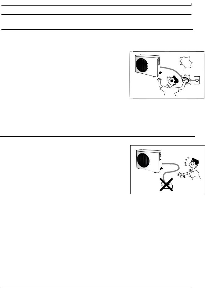
When installing the built-in type air conditioner, keep all electric cables such as the power cable and the connection cord in pipes, ducts, or cable channels to protect them from the danger of impact or any other incidents.
d a n g e r o u s
Avoid Dangerous Contact
1-2 Power supply and circuit breaker
If the power cord of the air conditioner is damaged, it must be replaced by the manufacturer or a qualified person in order to avoid a hazard.
The air conditioner must be plugged into an independent circuit if applicable or connect the power cable to the auxiliary circuit breaker.
An all pole disconnection from the power supply must be incorporated in the fixed wiring with a contact opening of >3mm.
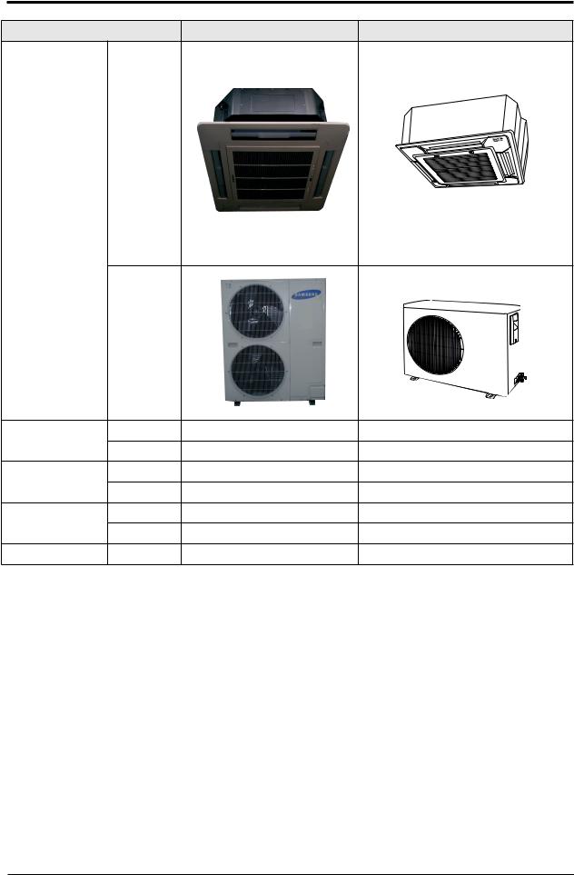
Do not extend an electric cord to the air conditioner.
The air conditioner must be plugged in after you complete the installation.
No Tapping and No Extension Cords
1-1 |
Samsung Electronics |

1-3 During operation
Do not repair the air conditioner at your discretion. |
|
It is recommended to contact a service center directly. |
|
Never spill any kind of liquid on the air conditioner. |
|
If this happens, turn off the air conditioner and contact an authorized service |
|
center. |
|
Do not insert anything between the airflow blades to prevent damage of the |
|
inner fan and consequent injury. Keep children away from the air conditioner. |
|
Do not place any obstacles in front of the air conditioner. |
|
Do not spray any kind of liquid into the indoor unit. If this happens, turn off the |
|
air conditioner and contact a service center. |
|
Make sure that the air conditioner is well ventilated at all times: |
|
Do not place a cloth or other materials over it. |
No children Nearby |
|
Remove the batteries if you don’t use the remote control for a long time. (If applicable)
Use the remote control within 7 meters from the indoor unit. (If applicable)
1-4 Disposing of the unit
Before throwing out the air conditioner, remove the batteries from the remote control.
When you dispose of the air conditioner, consult your dealer. If pipes are removed incorrectly, refrigerant may blow out and cause air pollution. When it contacts with your skin, it can cause skin injury.
The package of the air conditioner should be recycled or disposed of properly for environmental reasons.
1-5 Others
Never store or load the air conditioner upside down or sideways to prevent the damage to the compressor.
Young children or infirm persons should be always supervised when they use the air conditioner.
Max current is measured according to IEC standard for safety.
Current is measured according to ISO standard for energy efficiency.
Samsung Electronics |
1-2 |

2. Product Specifications
2-1 The Feature of Product
Energy saving function
Make a profit room temperature with energy saving function(high efficiency air conditioner).
Long Lasting Indoor & Outdoor Units
Anti-Corrosion Outdoor Cabinet & anti-Bacteria Indoor Heat Exchanger.
High Ceiling Operation
Broader and wider blow supports up to 3.6 meters high.
Built-in Drain Pump
Drain Pump for 750mm height difference.
Auto Changeover
Cooling or Heating automatic operation due to room temperature.
Long Piping
Max. 50m length & 30m height.
2-2 The abbreviated technology words & the definition of technology terms
Abbreviated technology words |
Definition of technology terms |
COMP |
One that compresses, especially a machine used to compress gases. |
( Full name:compressor ) |
|
BLOWER |
One that blows, especially a mechanical device, such as a fan, that pro- |
|
duces a current of air. |
FAN |
A device for creating a current of air or a breeze. |
ASSY CONTROL BOX |
A restraining device of air-condition, measure, or limit. |
(Full name : assemble control box) |
|
MOTOR |
Something, such as a machine or an engine, that produces or imparts- |
|
motion. |
ASSY EVAP / ASSY COND( Full name : |
Heat exchanger; A device, used to transfer heat from a fluid on oneside of |
assemble evaporator / assemble con- |
a barrier to a fluid on the other side without bringing the fluidsinto direct |
denser ) |
contact. |
2-1 |
Samsung Electronics |

2-3 Product Specifications
MODEL |
INDOOR UNIT |
|
|
|
CH140EAMC |
CH105EAMC |
CH070EAMC |
CH052EAMC |
CH094EAMC |
|
|
|
|
|
|
|
|
|
|
|
|
OUTDOOR UNIT |
|
UH140GAMC |
UH105GAMC |
UH070EAMC |
UH052EAMC |
UH094EAM1C |
||||
|
|
|||||||||
|
|
|
|
|
|
|
|
|
|
|
|
Cooling |
|
|
|
BTU/h |
48,000 |
34,120 |
23,885 |
18,426 |
30,708 |
|
|
|
|
|
|
|
|
|
|
|
Capacity |
|
|
|
W |
14,000 |
10,000 |
7,000 |
5,400 |
9,000 |
|
|
|
|
|
|||||||
|
|
|
|
|
|
|
|
|
|
|
Heating |
|
|
|
BTU/h |
52,800 |
36,510 |
24,567 |
20,473 |
32,414 |
|
|
|
|
|
|||||||
|
|
|
|
W |
15,400 |
10,700 |
7,200 |
6,000 |
9,500 |
|
|
|
|
|
|
||||||
|
Power Supply |
|
|
|
Φ/V/Hz |
3Φ/380~415 V/50Hz |
3Φ/380~415 V/50Hz |
220-240V~,50Hz |
220-240V~,50Hz |
220-240V~,50Hz |
Power |
Cooling |
|
|
|
W |
5,300 |
3,560 |
2,400 |
1,950 |
3,400 |
Input |
Heating |
|
|
|
W |
5,900 |
3,600 |
2,350 |
1,900 |
3,500 |
Running |
Cooling |
|
|
|
A |
9.20 |
6.20 |
11.0 |
8.5 |
15.5 |
Current |
Heating |
|
|
|
A |
10.00 |
6.30 |
11.0 |
8.6 |
16.0 |
|
Max current / power |
|
|
|
11.5A/6.5kW |
8.10A/4.39 kW |
13.5A/3.05kW |
11.8A/2.53 kW |
11.8A/2.53 kW |
|
|
|
|
|
|
|
|
|
|
|
|
|
|
Hi |
|
|
r.p.m |
600±20 |
540/520 ±20 |
460/440±20 |
400/380±20 |
460/440 ±20 |
|
|
|
|
|
|
|
|
|
|
|
|
Fan Speed |
Mid |
|
|
r.p.m |
560±20 |
500/480 ±20 |
440/420±20 |
380/360±20 |
440/420 ±20 |
|
|
|
|
|
|
|
|
|
|
|
|
|
Low |
|
|
r.p.m |
520±20 |
460/440 ±20 |
420/400±20 |
360/340±20 |
420/400 ±20 |
|
|
|
|
|
|
|
|
|
|
|
|
|
Hi |
|
|
m3/min |
29 |
24.5 |
18.5 |
14.0 |
18.5 |
|
Air Flow Rate |
Mid |
|
|
m3/min |
27 |
22.5 |
17.0 |
13.0 |
17.0 |
|
|
Low |
|
|
m3/min |
25 |
20.5 |
16.0 |
12.0 |
16.0 |
Indoor |
Noise Level( Cooling/ Heating) |
|
|
dB(A) |
49/50 |
47/48 |
43/44 |
43/44 |
43/44 |
|
|
|
|
|
|
|
|
|
|
|
|
Unit |
Heat Exchanger |
|
Type |
|
Slit, Φ7, 2RX13S, FP1.4 |
Slit, Φ7, 2RX12S, FP1.5 |
Slit, Φ7, 2RX8S, FP1.6 |
Slit, Φ7, 2RX8S, FP1.6 |
Slit,Φ7,2RX8S,FP1.6 |
|
|
RowsxStagesxFin pitch |
2*13*1.4 |
2*12*1.5 |
2*8*1.6 |
2*8*1.6 |
2*8*1.6 |
||||
|
Fan |
|
Type |
|
Turbo |
Turbo |
Turbo |
Turbo |
Turbo |
|
|
|
H |
|
|
mm |
298 |
298 |
218 |
218 |
218 |
|
Dimensions |
W |
|
|
mm |
840 |
840 |
840 |
840 |
840 |
|
|
D |
|
|
mm |
840 |
840 |
840 |
840 |
840 |
|
|
|
|
|
|
|
|
|
|
|
|
Weight |
Net/Gross |
|
|
kg |
29/35 |
28/34 |
25/31 |
25/31 |
25/31 |
|
|
|
|
|
|
|
|
|
|
|
|
Fan Speed |
Hi |
|
|
r.p.m |
1020±50 |
1080±50 |
900±50 |
940±50 |
980±50 |
|
|
|
|
|
|
|
|
|
|
|
|
Low |
|
|
r.p.m |
600±50 |
750±50 |
870±50 |
900±50 |
500±50 |
|
|
|
|
|
|||||||
|
|
|
|
|
|
|
|
|
|
|
|
Noise Level( Cooling/ Heating) |
|
|
dB(A) |
67/68 |
65/66 |
60/61 |
59/60 |
63/64 |
|
|
|
|
|
|
|
|
|
|
|
|
|
Fan |
|
Type |
|
Propeller |
Propeller |
Propeller |
Propeller |
Propeller |
|
|
|
|
|
|
|
|
|
|
|
|
|
|
|
Type |
|
Scroll , 3phase |
Scroll , 3phase |
Rotary 1 |
Rotary 1 |
Rotary 1 |
|
|
|
|
|
|
|
|
|
|||
|
Compressor |
Model |
BN62YFAMT |
AN42YBFMT |
G5A240JUAEM |
G8D190JUAEH |
NN40VAAMT |
|||
|
|
|
|
|
|
|
|
|
|
|
|
Output |
|
|
Btu/h |
56,640 |
37,200 |
24,100 |
19,995 |
10,200 |
|
|
|
|
|
|||||||
|
|
|
|
|
|
|
|
|
||
|
|
Protection |
External |
External |
Internal |
Internal |
Internal |
|||
|
|
|
|
|
|
|
|
|
|
|
Outdoor |
|
|
Type |
|
R410A |
R410A |
R410A |
R410A |
R410A |
|
|
|
|
|
|
|
|
|
|
|
|
Unit |
|
Charge |
|
|
g |
3,300(116.4oz) |
2,750(97.0oz) |
1,700(60oz) |
1,500(53oz) |
1,800(63.5oz) |
Refrigerant |
Adding |
|
|
g/m |
70 |
70 |
40 |
25 |
40 |
|
|
|
|
||||||||
|
|
Charge |
|
|||||||
|
|
|
|
|
|
|
|
|
||
|
|
Control |
Expansion Valve |
Expansion Valve |
Expansion Valve |
Expansion Valve |
Expansion Valve |
|||
|
|
|
|
|
|
|
|
|
|
|
|
Heat Exchanger |
|
Type |
|
Slit, Φ7 Wide fin |
Slit, Φ7 norm al fin |
Slit ,Φ7 norm al fin |
Slit ,Φ7 norm al fin |
Louver,Φ7normalfin |
|
|
RowsxStagesxFin pitch |
2*52*1.4 |
2*42*1.3 |
2*28*1.4 |
2*28*1.4 |
2*36*1.5 |
||||
|
|
H |
|
|
mm |
1128 |
931 |
648 |
648 |
798 |
|
Dimensions |
W |
|
|
mm |
932 |
880 |
880 |
880 |
880 |
|
|
D |
|
|
mm |
375 |
320 |
310 |
310 |
310 |
|
Weight |
Net/Gross |
|
|
kg |
121/136 |
87/92 |
60/67 |
59/66 |
74/82 |
|
|
|
|
|
|
|
|
|
|
|
|
Pipe O.D Size |
Liquid |
|
mm(inch) |
19.05(3/4”) |
19.05(3/4”) |
9.52(3/8”) |
6.35(1/4”) |
9.52(3/8”) |
|
|
|
|
|
|
|
|
|
|
|
|
|
Gas |
|
mm(inch) |
9.52(3/8”) |
9.52(3/8”) |
15.88(5/8”) |
12.70(1/2”) |
15.88(5/8”) |
||
|
|
|
||||||||
Piping |
|
|
|
|
|
|
|
|
|
|
Connection Method |
|
Flare |
Flare |
Flare |
Flare |
Flare |
||||
|
|
|
|
|
|
|
|
|
|
|
|
Between |
Height |
|
|
m |
Max.30 |
Max.30 |
Max.15 |
Max.15 |
Max.15 |
|
|
|
|
|
|
|
|
|
|
|
|
Pipe Length |
|
m |
Max.50 |
Max.50 |
Max.30 |
Max.30 |
Max.30 |
||
|
|
|
||||||||
Samsung Electronics |
2-2 |
2-4 The Comparative Specifications of Product
Item |
|
CH140EAMC |
CH44CA(Basic) |
|
|
Indoor Unit |
|
|
|
Design |
|
|
|
|
|
Outdoor Unit |
|
|
|
Net Weight |
Indoor Unit |
29Kg |
34Kg |
|
Outdoor Unit |
121Kg |
123Kg |
||
|
||||
Outer Dimension |
Indoor Unit |
298*840*840mm |
288*840*840mm |
|
(WxHxD) |
Outdoor Unit |
1128*932*375mm |
1240*930*385mm |
|
Noise |
Indoor Unit |
49dB |
52dB |
|
Outdoor Unit |
67dB |
62dB |
||
|
||||
Air Purifying System |
Filter |
Anti-bacterial Filter |
Anti-bacterial Filter |
2-3 |
Samsung Electronics |
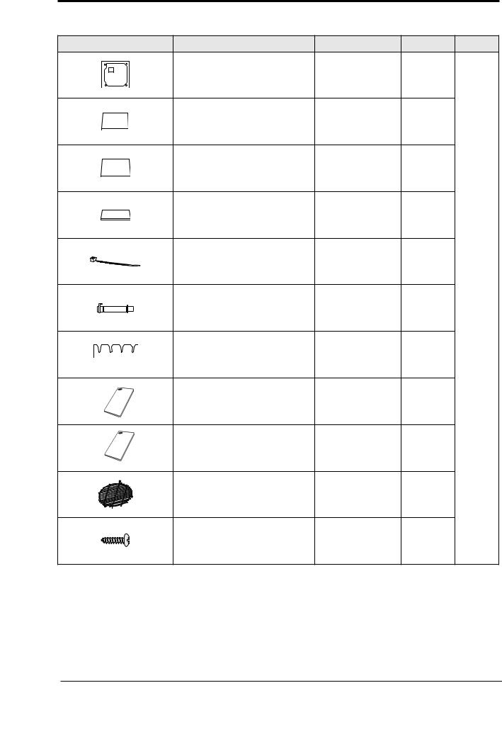
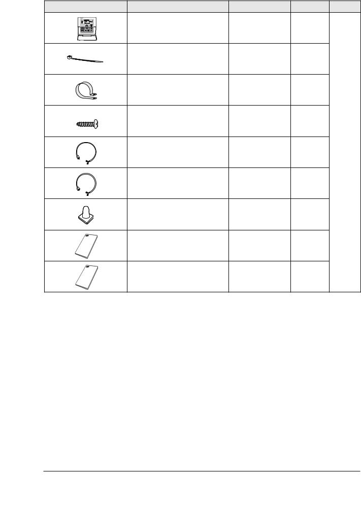
2-5 Accessory and Option Specifications
2-5-1 Accessories
Item |
Descriptions |
Code-No. |
Q'TY |
Remark |
|
Pattern sheet |
DB69-01490A |
1 |
|
|
Insulation drain in/out |
DB62-03440H/ |
1 |
|
|
DB62-03439H |
|
||
|
|
|
|
|
|
Insu Pipe Joint In 1/4 and 1/2 |
DB72-00143E/ |
1 |
|
|
DB72-00143G |
|
||
|
|
|
|
|
|
Insu Pipe Joint Out 1/4 |
DB62-03439J |
2 |
|
|
Cable-tie |
DB65-10088C |
8 |
|
|
Drain hose |
DB94-01065A |
1 |
Indoor |
|
Unit |
|||
|
|
|
|
|
|
Pad Stopper |
DB69-00165A |
1 |
|
|
Instruction manual |
DB98-26331A |
1 |
|
|
Installation manual |
DB98-26330A |
1 |
|
|
Safety net |
DB63-01480A |
1 |
|
|
M4x12 tapped Screw |
6002-2000213 |
4 |
|
Samsung Electronics |
2-4 |
Product Specifications
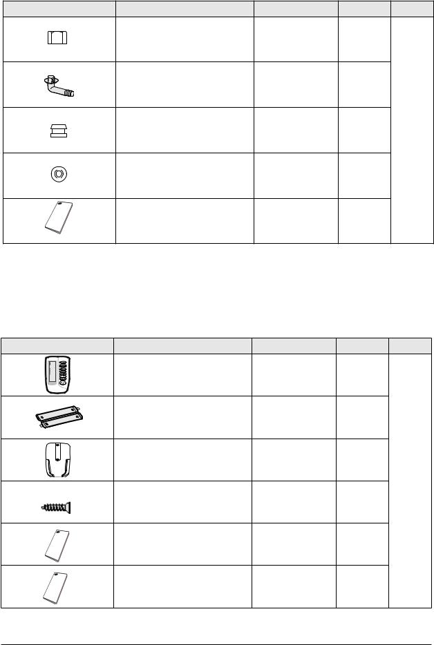
Accessories(cont.)
Item |
Descriptions |
Code-No. |
Q'TY |
Remark |
|
Nut-Flare |
DB60-30010B |
1 |
|
|
Drain Plug |
DB67-00477A |
1 |
|
|
Cap Drain |
DB63-10355C |
1 |
Outdoor |
|
Unit |
|||
|
|
|
|
|
|
Rubber Bracket Wire |
DB73-00218A |
2 |
|
|
Installation manual |
DB98-26328A |
1 |
|
2-5-2 Accessories
Wireless Remote Controller Accessories
Item |
Descriptions |
Code-No. |
Q'TY |
Remark |
|
Wireless remote controller |
DB93-00251G |
1 |
|
|
Battery |
DB47-90024A |
2 |
|
|
Remote control holder |
DB61-00204A |
1 |
|
|
STS 2S-2x10 tapped screw |
6002-000581 |
2 |
|
|
Owner’s instructions |
DB98-05156A |
1 |
|
|
Installation manual |
DB98-05184A |
1 |
|
2-5 |
Samsung Electronics |
|
|
|
|
Product Specifications |
Receiver & display unit & Wire kit |
|
|
|
|
Item |
Descriptions |
Code-No. |
Q'TY |
Remark |
|
Receiver & display unit |
DB93-01066A |
1 |
|
|
STS 2S-2x10 tapped screw |
- |
4 |
|
|
2S-4x12 tapped screw |
- |
2 |
|
|
|
|
|
Indoor |
|
|
|
|
Unit |
|
Owner’s instructions |
DB98-05160A |
1 |
|
|
Installation manual |
DB98-05186A |
1 |
|
|
Wire kit |
DB39-00223A |
1 |
|
|
Receiver & display unit |
DB93-01066A |
5 |
|
|
M4x16 tapped screw |
- |
7 |
|
|
Cable-tie |
- |
2 |
|
|
|
|
|
Standard |
|
|
|
|
type |
|
Owner’s instructions |
DB98-05160A |
1 |
|
|
Installation manual |
DB98-05186A |
1 |
|
|
Wire kit |
DB39-00223A |
1 |
|
Samsung Electronics |
2-6 |
Product Specifications
Wired Remote Controller Accessories
Item |
Descriptions |
Code-No. |
Q'TY |
Remark |
|
Wired remote controller |
DB93-01766C |
1 |
|
|
Cable-tie |
DB65-10088B |
2 |
|
|
Cable clamp |
DB65-10074E |
5 |
|
|
M4x16 tapped screw |
6002-000474 |
7 |
|
|
Indoor unit power drawing cable |
DB39-00221A |
1 |
|
|
Communication cable of the |
DB39-00933A |
1 |
|
|
wired remote controller |
|
||
|
|
|
|
|
|
Wire joint |
DB39-90020A |
1 |
|
|
Owner’s instructions |
DB98-15731A |
1 |
|
|
Installation manual |
DB98-15770A |
1 |
|
2-7 |
Samsung Electronics |

|
|
|
|
Product Specifications |
Centralized Controller Accessories |
|
|
|
|
Item |
Descriptions |
Code-No. |
Q'TY |
Remark |
|
Centralized controller |
DB97-00874B |
1 |
|
|
Cable-tie |
DB65-10088B |
2 |
|
|
Cable clamp |
DB65-10074E |
5 |
|
|
M4x16 tapped screw |
6002-000474 |
7 |
|
|
Owner’s instructions |
DB98-12721A |
1 |
|
|
Owner’s instructions |
DB98-12722A |
1 |
|
Function Controller Accessories
Item |
Descriptions |
Code-No. |
Q'TY |
Remark |
|
Function controller |
DB93-00757G |
1 |
|
|
Cable-tie |
DB65-10088B |
2 |
|
|
Cable clamp |
DB65-10074E |
6 |
|
|
M4x16 tapped screw |
6002-000474 |
7 |
|
|
Owner’s instructions |
DB98-05164A |
1 |
|
|
Owner’s instructions |
DB98-05190A |
1 |
|
Samsung Electronics |
2-8 |

Product Specifications
Transmitter Accessories
Item |
Descriptions |
Code-No. |
Q'TY |
Remark |
|
Transmitter |
- |
1 |
|
|
Transmitter power cable |
- |
1 |
|
|
Transmitter communication cable |
- |
1 |
|
|
Installation manual |
- |
1 |
|
7-day Scheduler Accessories
Item |
Descriptions |
Code-No. |
Q'TY |
Remark |
|
7-day Scheduler |
- |
1 |
|
|
Cable-tie |
- |
2 |
|
|
Cable clamp |
- |
2 |
|
|
M4x16 tapped screw |
- |
4 |
|
|
Owner’s instructions |
- |
1 |
|
|
Installation manual |
- |
1 |
|
2-9 |
Samsung Electronics |

3. Alignment and Adjustments
3-1 Indoor Display Error and Check Method
Error detection and reoperation
If error occurs during the operation, badness is indicated by LED flickering and all operation is stopped except LED. When reoperating by remote control and switch determine the error mode after normal operation.
Indoor unit LED lamp display at error detecting
|
|
|
LED lamp display |
|
|
||
Abnormal conditions |
|
|
|
|
|
|
Remarks |
Green |
Red |
Yellow |
Green |
Orange |
|||
|
|
|
|
|
|
|
|
|
|
|
|
|
|
|
|
|
|
|
|
|
|
|
|
|
|
|
|
|
|
|
|
Power reset |
|
X |
X |
X |
X |
|
|
|
|
|
|
|
|
|
|
Error of temperature sensor |
X |
X |
|
X |
X |
|
|
in the indoor unit (Open/Short) |
|
||||||
|
|
|
|
|
|
|
|
|
|
|
|
|
|
|
|
Error of heat exchanger sensor |
|
X |
|
|
X |
|
|
in the indoor unit |
|
|
|||||
|
|
|
|
|
|
|
|
|
|
|
|
|
|
|
|
Error of the outdoor temperature sensor |
|
X |
X |
|
X |
|
|
Error of the condensor temperature sensor |
|
||||||
Error of the discharge temperature sensor |
|
|
|
|
|
|
|
|
|
|
|
|
|
|
|
1. Error of electronic expansion valve close |
|
|
|
|
|
|
|
2. Error of electronic expansion valve open |
|
|
|
|
|
|
|
3. 2'nd detection of high temperature cond |
X |
X |
|
|
|
|
|
4. 2'nd detection of high temperature discharge |
|
||||||
|
|
|
|
|
|
|
|
5.Error of reverse phase |
|
|
|
|
|
|
|
6.Compressor down due to 6'th detection of freezing |
|
|
|
|
|
|
|
Detection of the float switch |
X |
X |
X |
|
|
|
|
|
|
|
|
|
|
|
|
Error of setting option switches for optional |
X |
X |
|
X |
|
|
|
accessories |
|
||||||
|
|
|
|
|
|
|
|
|
|
|
|
|
|
|
|
●: On : Flickering X: OFF
If you turn off the air conditioner when the LED is flickering, the LED is also turned off.
Samsung Electronics |
3-1 |
Alignment and Adjustments
LED Display
LED lamp display
Abnormal conditions |
Green |
Red |
Yellow |
Green |
Orange |
Remarks |
|
|
|
|
|
|
|
|
|
|
|
|
|
|
|
|
|
|
|
|
|
|
|
|
|
|
|
|
|
|
|
|
|
1. No communication for 2 minutes between indoor |
|
|
|
|
|
|
|
units (Communication error for more than 2 minutes) |
|
|
|
|
|
|
|
2. Indoor unit receiving the communication error from |
|
|
|
|
|
|
|
outdoor unit |
|
|
|
|
|
|
|
3. Outdoor unit tracking 3 minutes error |
X |
X |
|
|
X |
|
|
|
|
||||||
4.When sending the communciation error from the |
|
|
|
|
|
|
|
outdoor unit , the mismatching of the communication |
|
|
|
|
|
|
|
numbers and installed numbers after completion of |
|
|
|
|
|
|
|
tracking(Communication error for more than 2 minutes) |
|
|
|
|
|
|
|
|
|
|
|
|
|
|
|
EEPROM option error |
|
|
|
|
|
|
|
|
|
|
|
|
|
|
|
●: On : Flickering X: OFF
If you turn off the air conditioner when the LED is flickering, the LED is also turned off.
OPTION ITEMS
REMOCON |
SEG1 |
SEG2 |
SEG3 |
SEG4 |
SEG5 |
SEG6 |
SEG7 |
SEG8 |
SEG9 |
SEG10 |
SEG11 |
SEG12 |
MODEL |
|
|
|
|
|
|
|
|
|
|
|
|
CH140EAMC |
0 |
4 |
5 |
8 |
0 |
7 |
1 |
3 |
5 |
3 |
4 |
0 |
|
|
|
|
|
|
|
|
|
|
|
|
|
CH105EAMC |
0 |
4 |
4 |
0 |
0 |
7 |
1 |
F |
1 |
2 |
1 |
D |
|
|
|
|
|
|
|
|
|
|
|
|
|
CH070EAMC |
0 |
4 |
4 |
0 |
0 |
7 |
1 |
C |
5 |
0 |
D |
B |
|
|
|
|
|
|
|
|
|
|
|
|
|
CH052EAMC |
0 |
4 |
4 |
0 |
0 |
7 |
1 |
B |
1 |
0 |
A |
8 |
|
|
|
|
|
|
|
|
|
|
|
|
|
CH094EAMC |
0 |
4 |
6 |
8 |
0 |
7 |
1 |
0 |
5 |
2 |
1 |
D |
|
|
|
|
|
|
|
|
|
|
|
|
|
3-2 |
Samsung Electronics |
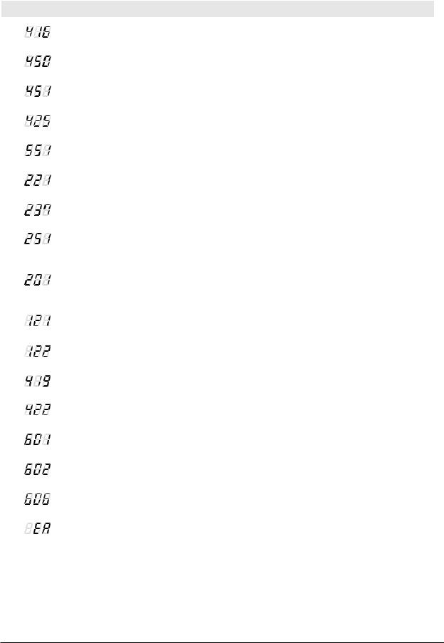
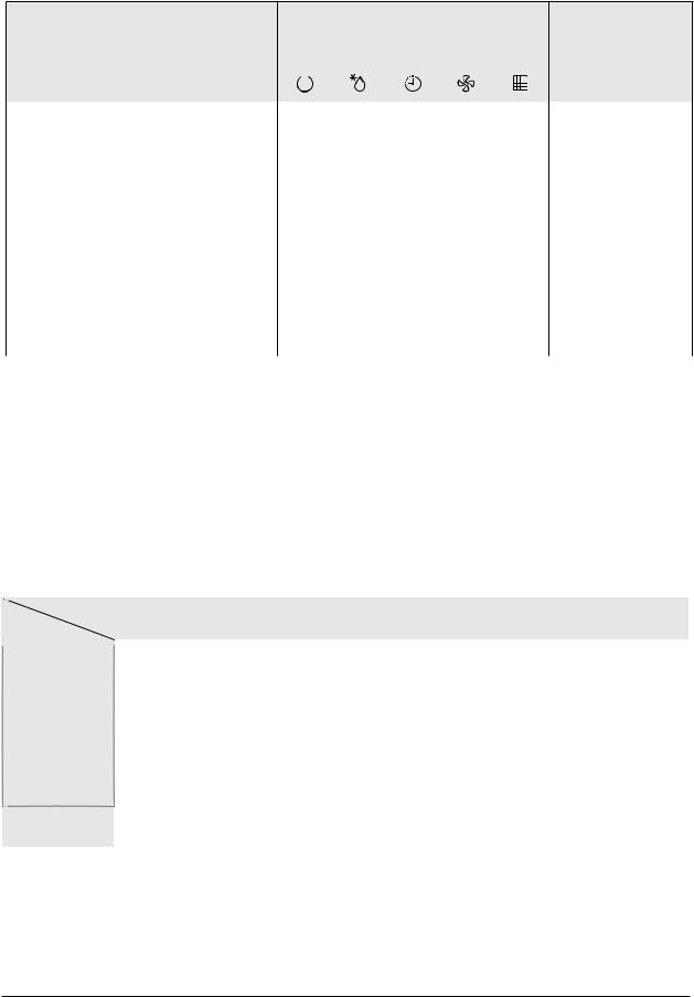
Alignment and Adjustments
Wired Remocon Error Display
Display |
Description |
Remarks |
|
|
|
|
Compressor down due to protection control of the discharge |
Error about protection |
|
|
|
|
temperature sensor |
control of the outdoor unit |
|
|
|
|
Control due to the condenser temperature sensor when cooling mode |
|
|
|
|
|
Error of the low pressure switch (Protection control) |
|
|
|
|
|
Reverse phase error (Protection control) |
|
|
|
|
|
In removing frost |
|
|
|
|
|
Error of the outdoor temperature sensor (Open/Short) |
Error about the outdoor unit |
|
sensor (Open/Short) |
|
|
|
Detection during the |
|
|
|
|
Error of condenser temperature sensor (Open/Short) |
operation of the indoor unit |
|
(sensing and sending errors |
|
|
|
|
|
|
into the communication data) |
|
Error of discharge temperature sensor (Open/Short) |
|
|
|
|
|
|
|
|
- System down caused by communication error after completion |
Communication and the |
|
of tracking |
indoor unit errors |
|
- Mismatching of the indoor unit numbers set with those communication |
|
|
after completion of 5 times tracking |
|
|
|
|
|
Error of temperature sensor in the indoor unit (Open/Short) |
Self-diagnosis of the indoor |
|
and outdoor unit |
|
|
|
|
|
|
|
|
Error of the heat exchanger sensor in the indoor unit (Open/Short) |
|
|
|
|
|
Error of electronic expansion valve open in the outdoor unit |
|
|
(when it is detected more than once) |
|
|
|
|
|
Error of electronic expansion valve close in the outdoor unit |
|
|
(when it is detected more than once) |
|
|
|
|
|
Error of communication between the indoor unit and the wired |
Wired remote controller |
|
errors |
|
|
remote controller |
|
|
|
|
|
Master wired remote controllerSlave wired remote controller |
|
|
|
|
|
COM1/COM2 Cross-installed error |
|
|
|
|
|
Error of setting option for wired remote controller COM2 |
|
|
|
|
Samsung Electronics |
3-3 |
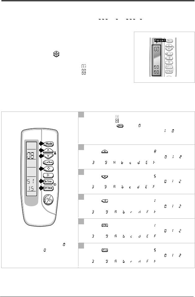
3-2 Setting Option Setup Method
ex) Option No. : 


Step 1 : Enter the Option Setup mode.
1st |
Take out the batteries of remote control. |
|
||
2nd |
Press the temperature |
|
button simultaneously and |
|
|
||||
|
insert the battery again. |
|
|
|
3rd |
Make sure the remocon display shown as |
. |
||
Step 2 : Enter the Option Setup mode and select your option according to the following procedure.
1
|
The default value is |
. |
|
|
|
|
Otherwise, push the |
button to . |
|
|
|
|
Every time you push the button, the display panel reads |
or |
|
||
|
repeatedly. |
|
|
|
|
1 |
2 |
|
|
|
|
2 |
|
|
|
|
|
Push the |
button to set the display panel to . |
|
|
||
|
|
|
|||
3 |
Every time you push the button, the display panel reads |
|
|||
|
. . . |
|
repeatedly. |
|
|
4 |
3 |
|
|
|
|
|
|
|
|
|
|
|
Push the |
button to set the display panel to . |
|
|
|
5 |
Every time you push the button, the display panel reads |
|
|
||
6 |
. . . |
|
repeatedly. |
|
|
|
4 |
|
|
|
|
|
Push the |
button to set the display panel to . |
|
|
|
|
Every time you push the button, the display panel reads |
|
|
||
|
. . . |
|
repeatedly. |
|
|
|
5 |
|
|
|
|
|
Push the |
button to set the display panel to . |
|
|
|
|
Every time you push the button, the display panel reads |
|
|
||
|
. . . |
|
repeatedly. |
|
|
Setting is not required if you must |
6 |
|
|
|
|
a value which has a default. |
Push the |
button to set the display panel to . |
|
|
|
|
Every time you push the button, the display panel reads |
|
|
||
|
. . . |
|
repeatedly. |
|
|
3-4 |
Samsung Electronics |

7 


8 
9 
10 
11  12
12 
7
Press  button, then the default value is


 .
.
8
Push the |
|
|
button to set the display panel to . |
|
|
Every time you push the button, the display panel reads |
|
|
|||
. . . |
repeatedly. |
|
|||
9
Push the |
button to set the display panel to . |
|
|
Every time you push the button, the display panel reads |
|
|
|
. . . |
repeatedly. |
|
|
10
Push the |
|
|
button to set the display panel to . |
|
|
Every time you push the button, the display panel reads |
|
|
|||
. . . |
repeatedly. |
|
|||
11
Push the |
|
|
button to set the display panel to . |
|
|
Every time you push the button, the display panel reads |
|
|
|||
. . . |
repeatedly. |
|
|||
Setting is not required if you must  a value which has a
  default.
12
Push the |
|
|
button to set the display panel to . |
|
|
Every time you push the button, the display panel reads |
|
|
|||
. . . |
repeatedly. |
|
|||
Step 3 : Upon completion of the selection, check you made right selections.
Press the Mode Selection key,  to set the display part to
  and check the display part.
The display part shows 


 .
.
Press the Mode Selection key,  set the display part to
  and check the display part. The display part shows

 .
.
Step 4 : Pressing the ON/OFF button (  )
)
When pressing the operation ON/OFF key with the direction of remote control for unit, the sound ’’Ding’’ or ’’Diriring’’
is heard and the OPERATION ICON(  ) lamp of the display is flickering at the same time, then the input of option is completed. (If the diriring sound isn’t heard, try again pressing the ON/OFF button.)
Step 5 : Unit operation test-run
First, Remove the battery from the remote control.
Second, Re-insert the battery into the remote control.
Third, Press ON/OFF button(  ) with the direction of remote control for set.
• Error Mode
1st |
If all lamps of indoor unit are flickering, Plug out, plug in power plug again and press ON/OFF key to retry. |
2nd |
If the unit is not working properly or all lamps are continuously flickering after setting the option code, see if the |
|
correct option code is set up for its model. |
Samsung Electronics |
3-5 |

4. Disassembly and Reassembly
Stop operation of the air conditioner and remove the power cord before repairing the unit.
4-1 Indoor Unit
CH140/105/070/052/094EAMC
No |
Parts |
Procedure |
|
|
Remark |
|||
|
|
|
|
|
|
|
|
|
1 |
Front Grille |
1) Push the tap on the Front Grille to open |
|
|
|
|
|
|
|
|
|
|
|
|
|||
|
- Dust-Collecting Filter |
it. |
|
|
|
|
|
|
|
|
|
|
|
|
|
|
|
|
|
|
|
|
|
|
|
|
|
|
|
|
|
|
|
|
|
2)Disassembly of Front Grille.
(1)Open the Front Grille at about 45˚ degrees and draw it forward.
(2)Disassemble the Safety Clip.
3) Filter Disassembly
(1) Draw the Dust-Collecting Filter
forward.
(2) Disassemble the Filter.
4-1 |
Samsung Electronics |
Disassembly and Reassembly
No |
Parts |
Procedure |
Remark |
4) Open the corner cover slowly to disassemble it. (There are three hooks.)
5) Pull the corner cover forward carefully by using two hands.
6)Loosen four bolts of the front panel slowly.
7) Loosen four screws of the safety net to disassemble it.
Samsung Electronics |
4-2 |
Disassembly and Reassembly
No |
Parts |
Procedure |
|
Remark |
|
|
|
|
|
|
|
|
|
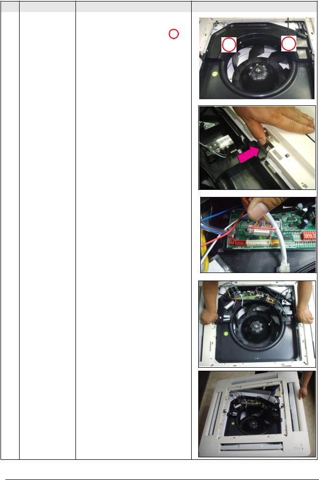
8) To uncover the Componet Electronic |
|
|
|
|
|
|
|
|
|
|
|
Box cover. |
|
|
|
|
|
(1) Loosen two screws in the mark |
. |
|
|
|
|
|
|
|
|
(2) Draw the both side hooks toward the arrow direction.
9)Disassemble two cables between the indoor unit and panel.
-Stepping motor connector.
-Receiving & display unit connector wire.
10)Hold on two hooks on both sides of
the indoor unit and disassemble the Front Panel.
11) Take away the disassembled Panel out of the main body.
4-3 |
Samsung Electronics |

|
|
|
Disassembly and Reassembly |
|
|
|
|
|
|
No |
Parts |
Procedure |
Remark |
|
|
|
|
|
|
2 |
Electronic Part Indoor |
1) Disconnect all Indoor and Outdoor |
|
|
|
|
|||
|
&Outdoor Connecting |
Cables connected to the Terminal Board. |
|
|
|
Cable |
|
|
|
|
|
|
|
|
3 |
Fan& Motor |
1) Disassemble the Fan Motor Wire |
|
|
Connector, Thermistor Wire Connector, |
|
|
Drain Pump Wire Connector and Float |
|
|
Switch Wire Connector. |
2) Loosen four screws in the mark  .
.
3) Disassemble the Base Control from the main body.
Samsung Electronics |
4-4 |

Disassembly and Reassembly
No |
Parts |
Procedure |
Remark |
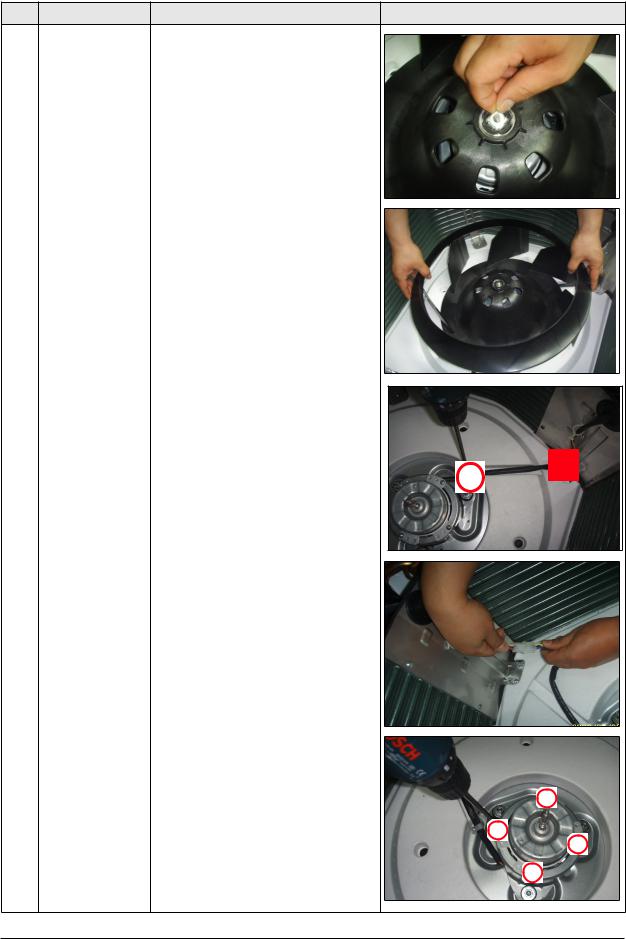
4) Disassemble the Rubber Cap Drain Socket to remove the water on the Cushion Drain.
(Prepare something like a gutter to put the water in.)
* In this point, you can check the Drain Pump Impeller operates well or not.
5)Loosen eight bolts in the mark .
.
* At first, there are 2 bolts per one corner and when reassembly, there should be at least 1 bolt per one corner fastened.
* 2 Bolts per one corner recommended..
6)Disassemble the Drain Cushion from the main body.
7) Loosen the nut
4-5 |
Samsung Electronics |
Disassembly and Reassembly
No |
Parts |
Procedure |
Remark |
8) Take out the Washer.
9) Lift the Fan to disassemble from the Motor.
10) Loosen the screw and disassemble the Motor Connector to disassemble Motor.
11)Loosen four screws in the mark  .
.
Samsung Electronics |
4-6 |
Disassembly and Reassembly
No |
Parts |
Procedure |
Remark |
|||
|
|
|
|
|
|
|
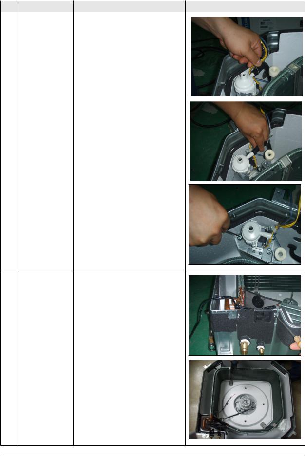
4 |
Drain Pump |
1) Disassemble the Hose from the Drain |
|
|
|
|
|
|
|
||||
|
|
Pump. |
|
|
|
|
|
|
|
|
|
|
|
|
|
|
|
|
|
|
|
|
|
|
|
|
|
2) Loosen the 3 bolts to disassemble the Drain Pump from the main body.
5 |
Heat Exchanger |
1) Loosen 2 screws to disassemble the |
|
|
Cover Pipe beside the main body. |
2) Loosen two screws fixing the Holder Evap to disassemble the Heat Exchanger.
4-7 |
Samsung Electronics4-6 |

|
|
|
Disassembly and Reassembly |
|
|
|
|
|
|
No |
Parts |
Procedure |
Remark |
|
|
|
|
|
|
6 |
Front Panel |
1) Loosen two screws to disassemble the |
|
|
|
|
|||
|
(PCB Part) |
Cover PCB. |
|
|
|
|
|
|
|
2)Loosen the screw fixing the PCB to disassemble it.
3)Disassemble the PCB Wire from the PCB.
4)Disassemble the Button PCB from the PCB.
Samsung Electronics |
4-8 |
Disassembly and Reassembly
No |
Parts |
Procedure |
Remark |
|
|
|
|
|
|
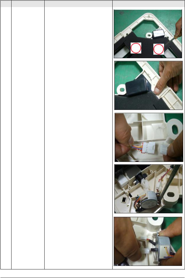
7 |
Panel Front |
1) Loosen the two screws fixing the Cover |
|
|
|
|
|||
|
(Stepping Motor) |
Side. (There are 4 Cover Side.) |
|
|
2) Draw two hooks then lift up the Cover Side.
3)Disassemble the Stepping Motor Wire Connected.
4) Disassemble the Stepping Motor from the Panel Front.
5)Disassemble the link and bracket from the Stepping Motor.
4-9 |
Samsung Electronics |

Disassembly and Reassembly
4-2 Outdoor Unit
UH140GAMC |
|
|
|
|
|
|
|
|
|
No |
Parts |
|
Procedure |
Remark |
1 |
Cabinet |
1) Turn off the equipment and disassemble |
||
|
|
the power cable. |
|
|
|
|
2) |
Uncover the Cabinet Top. |
|
|
|
3) |
Uncover the Control Box Cover |
|
|
|
4) |
Pull out the assemble Cable. |
|
|
|
5) |
Disassemble the Cabinet Side |
|
|
|
6) |
Disassemble the Cabinet |
Front. |
Check whether each part is fixed to the electronic connector firmly at the time of part assembly.
2Fan Motor & 1) Loosen the blot fixing the Propeller Fan.
Propeller Fan |
2) Disassemble the Fan. |
Samsung Electronics |
4-10 |
Disassembly and Reassembly
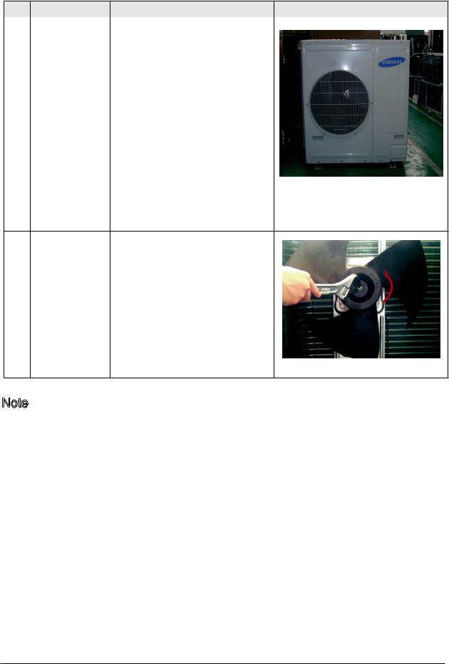
UH105GAMC/UH070/052EAMC,UH094EAM1C
No |
Parts |
|
Procedure |
Remark |
1 |
Cabinet |
1) Turn off the equipment and disassemble |
||
|
|
the power cable. |
|
|
|
|
2) |
Uncover the Cabinet Top. |
|
|
|
3) |
Uncover the Control Box Cover |
|
|
|
4) |
Pull out the assemble Cable. |
|
|
|
5) |
Disassemble the Cabinet Side |
|
|
|
6) |
Disassemble the Cabinet |
Front. |
Check whether each part is fixed to the electronic connector firmly at the time of part assembly.
2Fan Motor & 1) Loosen the blot fixing the Propeller Fan.
Propeller Fan |
2) Disassemble the Fan. |
Note :
The above pictures are only references
4-11 |
Samsung Electronics |
|
 Loading...