


AM200xXV Series
Samsung AM200xXV Series, AM120xXV Series, AM220xXV Series, AM100xXV Series, AM160xXV Series Service Manual
...
AIR CONDITIONER CONTENTS
SYSTEM AIR CONDITIONER
OUTDOOR UNIT
AM080/100/120/140/160/180/200/220/240/2606XV666
AM080/100/120/200FXWA666
AM080/100/120/140/160/180/200/220JXVA66
AM140/160/180/200/220/240/260/280/300KXV666
1. Precautions
2. Product Specifications
3. Disassembly and Reassembly
4. Troubleshooting
5. PCB Diagram and Parts List
6. Wiring Diagram
7. Cycle Diagram
8. Key Options
9. Test Operation

Section 0
Samsung Electronics 1
Contents
1. Precautions .......................................................................................................... 1-1
1-1 Precautions for the Service ......................................................................................................................................1-1
1-2 Precautions for the Static Electricity and PL .....................................................................................................1-1
1-3 Precautions for the Safety ........................................................................................................................................1-1
1-4 Precautions for Handling Refrigerant for Air Conditioner ..........................................................................1-2
1-5 Precautions for Welding the Air Conditioner Pipe .........................................................................................1-2
1-6 Precautions for Additional Supplement of Air Conditioner Refrigerant ...............................................1-2
1-7 Other Precautions ........................................................................................................................................................1-2
2. Product Specifications ....................................................................................... 2-1
2-1 The Feature of Product ..............................................................................................................................................2-1
2-1-1 Feature ...............................................................................................................................................................2-1
2-1-2 Changes in comparison to basic mode ................................................................................................2-3
2-1-3 Structure of product(Heat Pump) ...........................................................................................................2-9
2-1-4 Structure of product(Heat Recovery) ................................................................................................. 2-10
2-1-5 Structure of product(Power supply for 460V, 60Hz, 3Φ) ............................................................ 2-11
2-1-6 Structure of product (DVM S WATER) .................................................................................................2-12
2-1-7 Structure of product (Heat Pump AM666KX6 Series)............................................................. 2-13
2-2 Product Specifications ........................................................................................................................................... 2-14
2-2-1 Outdoor Unit ................................................................................................................................................2-14
2-3 Accessory and Option Specifications ............................................................................................................... 2-43
2-3-1 Accessories ....................................................................................................................................................2-43
3. Disassembly and Reassembly ........................................................................... 3-1
3-1 Necessary Tools .............................................................................................................................................................3-1
3-2 Disassembly and Reassembly .................................................................................................................................3-2
3-2-1 AM080/100/120JXV666 ...........................................................................................................................3-2
3-2-2 AM140FXVAGH, AM140JXV6GH .........................................................................................................3-12
3-2-3 AM160/180/200/220/240/2606XV666, AM140JXVA6H ........................................................ 3-22
3-2-4 AM080/100/120FXWA66 ....................................................................................................................... 3-33
3-2-5 AM200FXWA66 .........................................................................................................................................3-41
3-2-6 AM140/160KXVG66, AM140/160/180KXVA66...........................................................................3-48
3-2-7 AM180/200/220KXVG66, AM200/220KXVA66...........................................................................3-55
3-2-8 AM240/260/280/300KXV666, AM080KXVS66 .......................................................................... 3-63
3-3 Caution at compressor exchange ...................................................................................................................... 3-72
3-4 MCU ................................................................................................................................................................................ 3-77
3-5 EEV KIT ........................................................................................................................................................................... 3-78
4. Troubleshooting .................................................................................................. 4-1
4-1 Check-up Window Description ..............................................................................................................................4-1
4-2 Service Operation ........................................................................................................................................................4-2
4-2-1 Special Operation ..........................................................................................................................................4-2
4-2-2 DVM S Models EEPROM Code Table ...................................................................................................4-12
4-2-3 Number Display Method ........................................................................................................................ 4-13
4-3 Appropriate Measures for Different Symptom ............................................................................................. 4-18
4-3-1 Outdoor Unit Operation Flow ............................................................................................................... 4-17
4-3-2 Main PCB has no power phenomenon ............................................................................................. 4-21
4-3-3 Communication Error between Indoor and Outdoor Units during Tracking.................... 4-22
4-3-4 Communication Error between Indoor and Outdoor Units after Tracking ........................ 4-24
4-3-5 Communication error between main and sub Unit of outdoor unit or
between outdoor units ............................................................................................................................ 4-25
4-3-6 Internal Communication error of the Outdoor Unit C-Box ....................................................... 4-26
4-3-7 Internal PCB Communication error of the Outdoor Unit C-Box..............................................4-27
4-3-8 MCU branch part setup error-inconsecutive connection with the use
of 2 branch Parts .........................................................................................................................................4-29

Section 0
2 Samsung Electronics
Contents
4-3-9 MCU branch part setup error-Repeated setup for the same address over 3 times ........ 4-30
4-3-10 MCU branch part setup error-non-installed address setup ................................................... 4-31
4-3-11 Setup Error for MCU Branch part-Setup Error for MCU Quantity Used ............................. 4-32
4-3-12 MCU branch part setup error-Overlapping Indoor unit Address setup ...........................4-33
4-3-13 MCU branch part setup error_Set as being used without connection
to an Indoor unit ...................................................................................................................................... 4-34
4-3-14 MCU branch part setup error-Connect an Indoor unit to a branch part
not being used ..........................................................................................................................................4-35
4-3-15 MCU branch part setup error-Connect more Indoor units than what is
actually set up in MCU ........................................................................................................................... 4-36
4-3-16 MCU/MCU subcooler entrance/exit sensor error (Open/Short) ........................................... 4-37
4-3-17 Outdoor Temperature Sensor Error .................................................................................................. 4-38
4-3-18 Cond Out Temperature Sensor Error (Open/Short) ...................................................................4-39
4-3-19 Outdoor Cond Out sensor breakway error ................................................................................... 4-40
4-3-20 Compressor Discharge or TOP 1/2 Temperature sensor error ............................................... 4-42
4-3-21 Compressor Discharge or TOP temperature sensor breakway error ..................................4-43
4-3-22 E269 : Suction Temperature sensor breakway error .................................................................4-44
4-3-23 High Pressure sensor error (Open/Short) .......................................................................................4-45
4-3-24 Low Pressure sensor error (Open/Short) ........................................................................................ 4-46
4-3-25 Suction Temperature sensor error (Open/Short) ........................................................................ 4-47
4-3-26 Liquid Pipe Temperature sensor error (Open/Short) ................................................................. 4-48
4-3-27 EVI In Temperature sensor error (Open/Short) ............................................................................ 4-49
4-3-28 EVI Out Temperature sensor error (Open/Short) ........................................................................ 4-50
4-3-29 Suction-2 Temperature Sensor Error (Open/Short) ...................................................................4-51
4-3-30 Measures of other outdoor unit error ............................................................................................. 4-52
4-3-31 E407 : Comp. Down due to High Pressure Protection Control .............................................4-53
4-3-32 E410 : Comp. Down due to Low Pressure Protection Control ...............................................4-55
4-3-33 E416 : Suspension of starting due to Compressure discharge
temperature sensor/Top temperature sensor .................................................................4-57
4-3-34 3-phase Input Wiring error ...................................................................................................................4-58
4-3-35 E428 : Suspension of starting by abnormal compression ratio ........................................... 4-59
4-3-36 EVI EEV Open error ..................................................................................................................................4-60
4-3-37 Refrigerant leakage error ...................................................................................................................... 4-61
4-3-38 Prevention of heating/cooling operation due to outdoor temperature ..........................4-62
4-3-39 Prevention of heating refrigerant charge due to outdoor temperature ..........................4-63
4-3-40 CH wire breaking error........................................................................................................................... 4-64
4-3-41 Fan starting error ......................................................................................................................................4-66
4-3-42 Fan lock error ............................................................................................................................................. 4-67
4-3-43 Momentary Blackout error .........................................................................................................................4-69
4-3-44 Outdoor Fan Motor overheating ....................................................................................................... 4-70
4-3-45 Fan IPM Overheat error .......................................................................................................................... 4-71
4-3-46 Compressor starting error ....................................................................................................................4-72
4-3-47 COMP Overcurrent error ....................................................................................................................... 4-74
4-3-48 Overvoltage/Low voltage error ..........................................................................................................4-78
4-3-49 DC Link voltage sensor error ............................................................................................................... 4-79
4-3-50 Fan Motor Overcurrent error ...............................................................................................................4-80
4-3-51 Input/Output Current sensor error ................................................................................................... 4-82
4-3-52 Outdoor Fan PCB Overvoltage/Low voltage error .....................................................................4-83
4-3-53 Hall IC(Fan) error ....................................................................................................................................... 4-84
4-3-54 Inverter Overheat error .......................................................................................................................... 4-85
4-3-55 Option setting error of outdoor unit ............................................................................................... 4-86
4-3-57 Error due to using single type outdoor unit in a module installation ............................... 4-87
4-3-57 Indoor unit and MCU address duplication error ......................................................................... 4-88

Section 0
Samsung Electronics 3
Contents
5. PCB Diagram and Parts List ............................................................................... 5-1
5-1 ASS'Y PCB MAIN ...........................................................................................................................................................5-1
5-2 ASS'Y PCB MAIN-HUB ................................................................................................................................................5-4
5-3 ASS’Y PCB INVERTER ..................................................................................................................................................5-8
5-4 ASS’Y PCB FAN ........................................................................................................................................................... 5-12
5-5 ASS’Y PCB EMI .......................................................................................................................................................... 5-16
5-6 SUB-COMM ................................................................................................................................................................ 5-19
6. Wiring Diagram ................................................................................................... 6-1
6-1 AM080/100/120/140/160/180/200/220FXV666 ..........................................................................................6-1
6-2 AM080/100/120/200FXWA66 ...............................................................................................................................6-3
6-3 AM240/26066XV66 .................................................................................................................................................6-5
6-4 AM080JXVAFH ...............................................................................................................................................................6-7
6-5 AM100/120JXVAFH .....................................................................................................................................................6-9
6-6 AM140/160/180/200JXVAFH ................................................................................................................................6-11
6-7 AM080/100/120/140/160/180/200/220JXVAJH ........................................................................................... 6-13
7. Cycle Diagram ...................................................................................................................7-1
7-1 AM080/100/1206XV66H ........................................................................................................................................7-1
7-2 AM1406XV6GH ...........................................................................................................................................................7-1
7-3 AM160/180/200/2206XV66H ..............................................................................................................................7-2
7-4 AM080/100/1206XV6GR .........................................................................................................................................7-2
7-5 AM1406XV6GR............................................................................................................................................................7-3
7-6 AM160/180/200/2206XV6GR ...............................................................................................................................7-3
7-7 AM080/100/120FXWA66 ........................................................................................................................................7-4
7-8 AM200FXWA66 ...........................................................................................................................................................7-4
7-9 AM240/260HXVAGH/EU ............................................................................................................................................7-5
7-10 AM240/260/280KXVG66, AM280/300KXVA66, AM080KXVS66 ......................................................7-5
7-11 AM180/200/220KXVG66, AM200/220KXVA66 .........................................................................................7-6
7-12 AM140/160KXVG66, AM140/160/180KXVA66 .........................................................................................7-6
7-13 Cooling operation (H/R) ..........................................................................................................................................7-6
7-14 Main cooling operation (H/R) ...............................................................................................................................7-7
7-15 Heating operation (H/R) .........................................................................................................................................7-8
7-16 Main heating operation (H/R) ..............................................................................................................................7-9
7-17 Cooling operation (H/P) .......................................................................................................................................7-10
7-18 Heating operation (H/P) ......................................................................................................................................7-11
7-19 Cooling operation(H/R) - AM080/100/120/200FXWA66 .....................................................................7-12
7-20 Main cooling operation(H/R) ............................................................................................................................. 7-14
7-21 Heating operation(H/R) .......................................................................................................................................7-15
7-22 Main heating operation(H/R) ............................................................................................................................7-16
7-23 Cycle Component Function Explanation ...................................................................................................... 7-17
8. Key Options .........................................................................................................8-1
8-1 Outdoor unit option switch settings ...................................................................................................................8-1
8-2 How to set the key function of the outdoor unit ...........................................................................................8-4
8-3 How to check the view mode using a tact switch ...................................................................................... 8-12
9. Test Operation .....................................................................................................9-1
9-1 Auto Trial Operation ....................................................................................................................................................9-1
9-1-1 Auto Trial Operation Synopsis ..................................................................................................................9-1
9-1-2 Auto Trial Operation functions .................................................................................................................9-3
9-1-3 How to troubleshoot of the "Undetermined"....................................................................................9-4
9-2 Amount of refrigerant automatically checking ............................................................................................ 9-14
9-3 Model Naming ...........................................................................................................................................................9-15

Samsung Electronics 1-1
1. Precautions
1-1 Precautions for the Service
OUse the correct parts when changing the electric parts.
– Please check the labels and notices for the model name, proper voltage, and proper current for the electric parts.
OFully repair the connection for the types of harness when repairing the product after breakdown.
– A faulty connection can cause irregular noise and problems.
OWhen disassembling or assembling, make sure that the product is laid down on a work cloth.
– Doing so will prevent scratching to the exterior of the rear side of the product.
OCompletely remove dust or foreign substances on the housing, connection, and inspection parts when performing repairs.
– This can prevent fire hazards for tracking, short, etc.
OPlease tighten the service valve of the outdoor unit and the valve cap of the charging valve as securely as possible by using
a monkey spanner.
OCheck whether the parts are properly and securely assembled after performing repairs.
– These parts should be in the same condition as before the repair.
1-2 Precautions for the Static Electricity and PL
OPlease carefully handle the PCB power terminal during repair and measurement when it is turned on since it is vulnerable
to static electricity.
– Please wear insulation gloves before performing PCB repair and measurement.
OCheck if the place of installation is at least 2m away from electronic appliances such as TV, video players, and stereos.
– This can cause irregular noise or degrade the picture quality.
OPlease make sure the customer does not directly repair the product.
– Arbitrary dismantling may result in electric shock or fire.
1-3 Precautions for the Safety
ODo not pull or touch the power plug or the subsidiary power switch with wet hands.
– This may result in electric shock or fire.
OIf the power line or the power plug is damaged, then it must be changed since this is a hazard.
ODo not bend the wire too much or position it so that it can be damaged by a heavy object on top.
– This may result in electric shock or fire.
OThe use of multiple electric outlets should be prohibited.
– This may result in electric shock or fire.
OGround the connection if it is necessary.
– The connection must be grounded if there is any risk of electrical short due to water or moisture.
OUnplug the power or turn off the subsidiary power switch when changing or repairing electrical parts.
– Doing so will prevent electric shock.
OExplain to workers that the battery for the remote control needs to be separated for storage purposes when the product
will not be used for a long time.
– This can cause a problem for the remote control since battery fluid may trickle out.

1-2 Samsung Electronics
1-4 Precautions for Handling Refrigerant for Air Conditioner
Environmental Cautions: Air pollution due to gas release
OSafety Cautions
If liquid gas is released, then body parts that come into contact with it may experience frostbite/blister/numbness.
If a large amount of gas is released, then suffocation may occur due to lack of oxygen. If the released gas is heated, then noxious
gas may be produced by combustion.
OContainer Handling Cautions
Do not subject container to physical shock or overheating. (Flowage is possible while moving within the regulated pressure.)
1-5 Precautions for Welding the Air Conditioner Pipe
ODangerous or flammable objects around the pipe must be removed before the welding.
OIf the refrigerant is kept inside the product or the pipe, then remove the refrigerant prior to welding.
If the welding is carried out while the refrigerant is kept inside, the welding cannot be properly performed. This will also produce
noxious gas that is a health hazard. This leakage will also explode with the refrigerant and oil due to an increase in the refrigerant
pressure, posing a danger to workers.
OPlease remove the oxide produced inside the pipe during the welding with nitrogen gas.
Using another gas may cause harm to the product or others.
1-6 Precautions for Additional Supplement of Air Conditioner Refrigerant
OPrecisely calculate the refrigerant by using a scale and S-net, and proceed with the test operation.
Excessive supplement can cause harm to the product since it can cause an inflow of the liquid refrigerant into the compressor.
ODo not heat the refrigerant container for a forced injection.
This may cause harm to the product or others since the refrigerant container may burst.
ODo not operate the product after removing the product safety pressure switch and sensor.
If the product is blocked inside, then this may cause harm to the product or others due to the excess pressure increase of the
refrigerant gas.
1-7 Other Precautions
OThere should be no leakage of the pipes after installation. When withdrawing the refrigerant, the compressor should be
stopped before removing the connecting pipe.
If the compressor is operating while the refrigerant pipe is not correctly connected and the service valve is opened, then
air and other substances can enter the pipe. The interior of the refrigerant cycle may then build up excessive high pressure
resulting in explosion and damage.
Samsung Electronics 2-1
2. Product Specifications
2-1 The Feature of Product
2-1-1 Feature
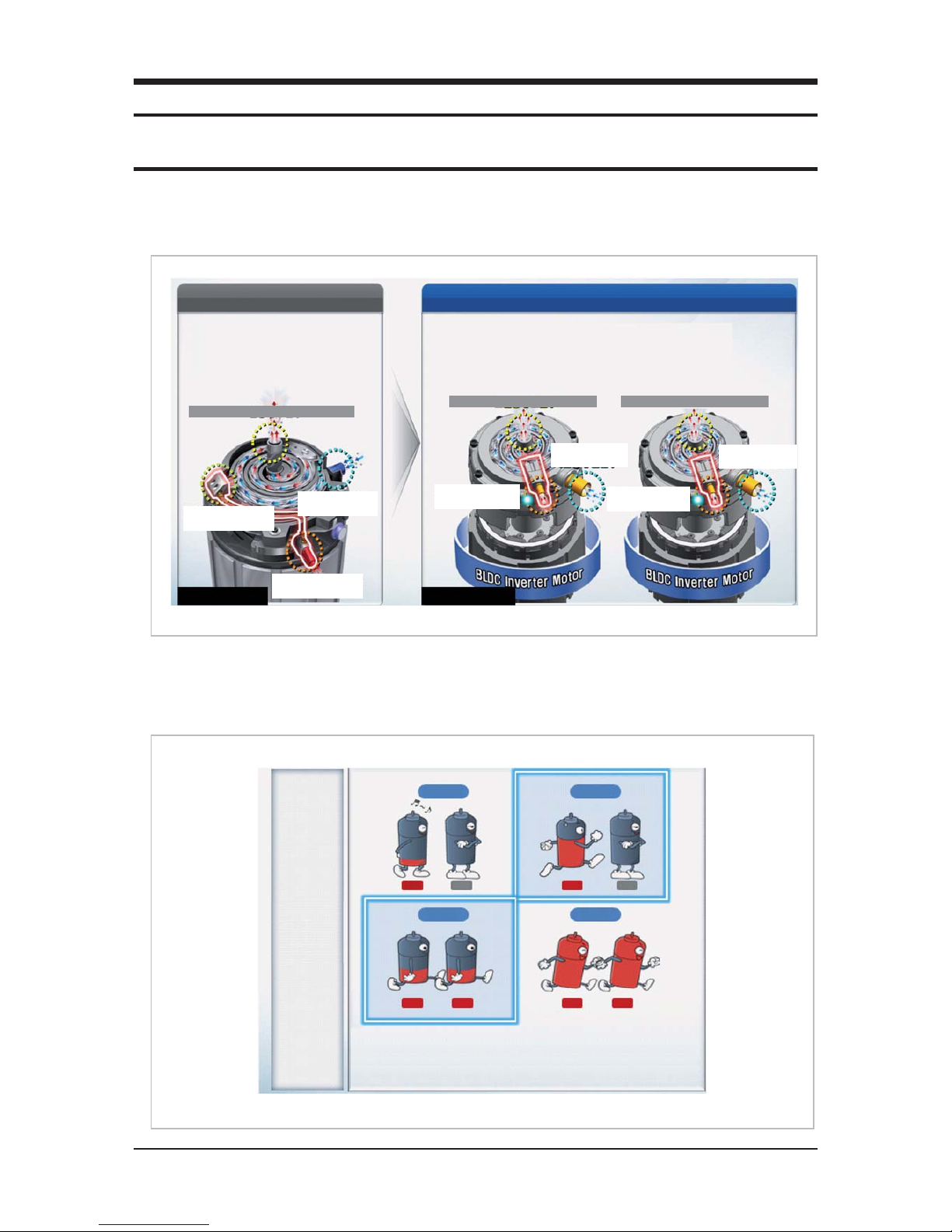
Q Dual SSC System Technology
When load changes, capacity amendment that is soft by continuous operation of Dual Inverter is available.
Q Dual Smart Inverter System
DSC System
Digital base Inverter base
. DVI variable + DVI constant speed
. AC Motor
. 2 generation, Vapor Injection
. Dual Smart Inverter : SSC + SSC
. BLDC Inverter Motor (14~160Hz driving)
. 3 generation, Vapor Injection
(Performance maximization of low temperature heating)
DSI System
High Pressure Refrigerant Outlet
Medium Pressure
Refrigerant Injection
Low Pressure
Refrigerant Inlet
Low Pressure
Refrigerant Inlet
3 generation,
Vapor Injection
3 generation,
Vapor Injection
Low Pressure
Refrigerant Inlet
High Pressure Refrigerant Outlet High Pressure Refrigerant Outlet
Medium Pressure
Refrigerant Inlet
Capacity
Variable
Ŷ Compressor driving : When load changes, is variable by fast inverter frequency.
Ŷ Amenities elevation : ᇹ0.5°C
Step 1
ON OFF
Step 2
Step 3 Step 4
ON OFF
ON ON ON ON
Product Specications
2-2 Samsung Electronics
Feature
(cont.)
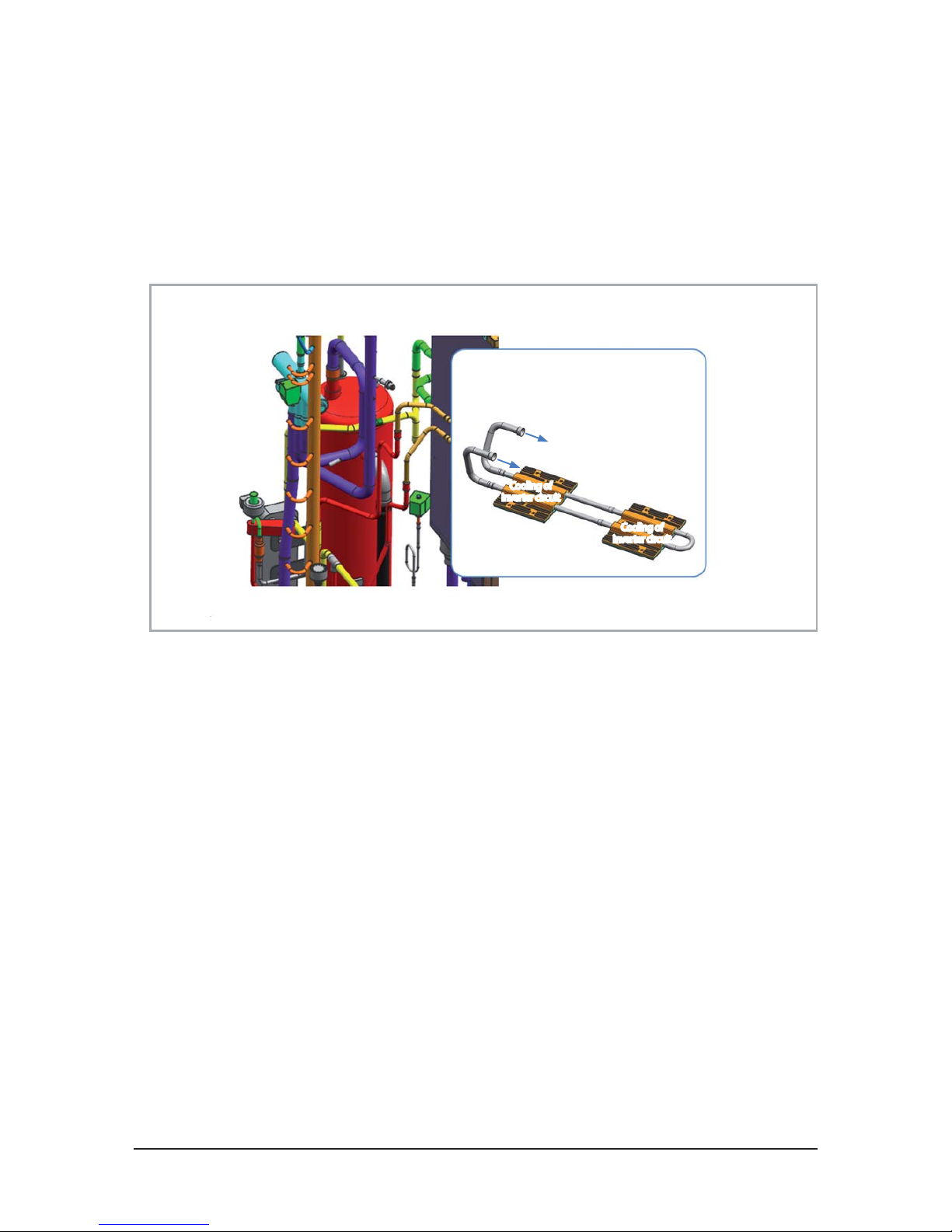
QInverter circuit refrigerant cooling technology
- Applied high eciency refrigerant cooling circuit. Secured stable Inverter PCB cooling performance.
- Air cooling method : When natural convection / electric heat performance is low and is high load, eciency is fallen.
- Refrigerant cooling system : Forced circulation / electric heat performance is high and control of (thermal conductivity is
10 times higher than air) load is available.
Cooling of
inverter circuit
Refrigerant cooling system :
It is cooling technology of inverter circuit that use
refrigerating cycle technology.
Cooling of
inverter circuit
Product Specications
Samsung Electronics 2-3
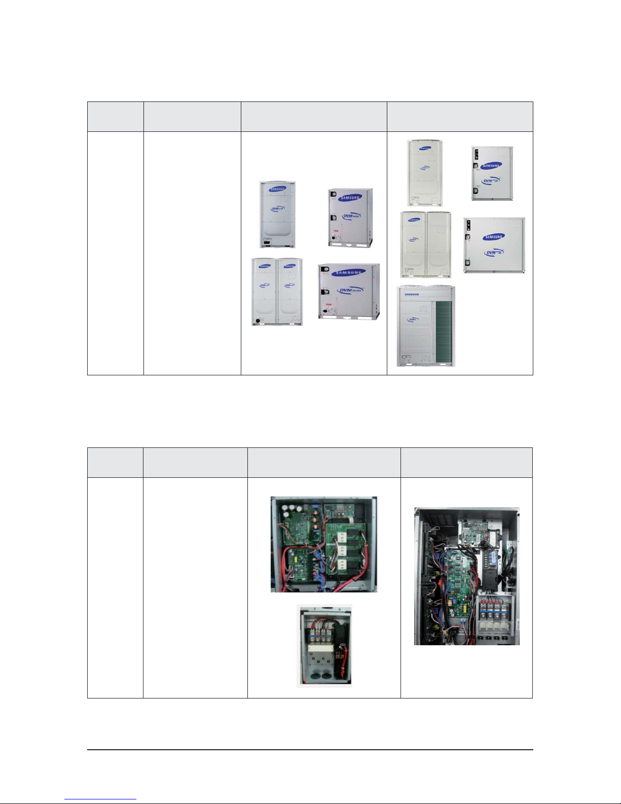
2-1-2 Changes in comparison to basic mode
Changed
part
Changed item
and feature
Basic After changed
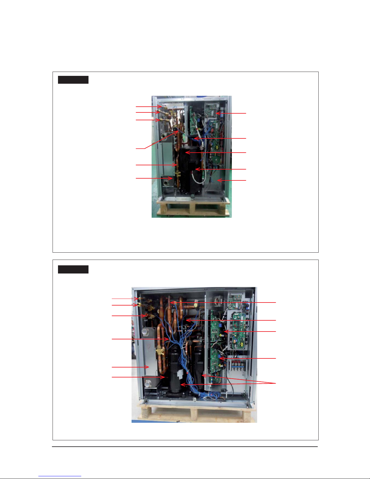
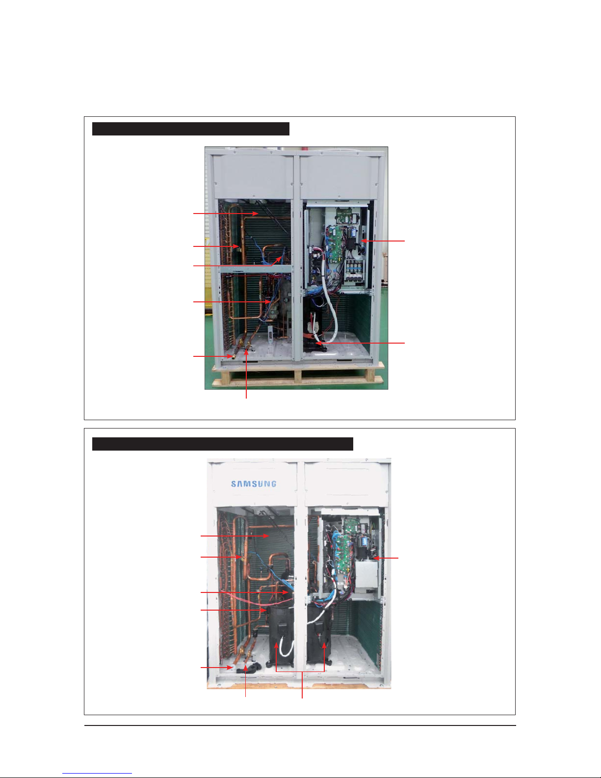
Control Box
structure
Monolayer structure ࣖ Double
Layer Structure
- Inverter technology integration
(Inverter control circuit
composition)
- C/Box volume maximum use
Built-in type Controller embodi-
ment
- Integrated power supply
+ control unit
- Piping service easiness
Q Control Box & PCB
Changed
part
Changed item
and feature
Basic After changed
CABINET
Change the color :
TOUCH GRAY
ࣖ EARTH BROWN
Wire Harness installation part
change
LOGO change
Product Specications
2-4 Samsung Electronics
Changes in comparison to basic mode (cont.)
Changed
part
Changed item
and feature
Basic After changed
Main PCB
Change Main PCB
- Separation for load / control.
- Option resistance delete by model.
(standardization)
- When do PCB replace, need option
download.
Hub PCB
Hub PCB newly application
- Separation for load / control.
- Enhanced fixing of load / sensor wire.
FAN PCB
Use controller of 3 phase power
- Prevented phase unbalance.
- Temperature protection of IPM.
Inverter PCB
(Compressor
Control PCB)
Applied inverter Compressor
- Refrigerant cooling method
- Mount power relay on PCB
EMI PCB
3 phase power EMI PCB
- Fuse mount
Communication
Terminal block
- Mount communication terminal block
on PCB
Q
AM080/100/120/140/160/180/200/220JXV666
Product Specications
Samsung Electronics 2-5
Changes in comparison to basic mode (cont.)
Changed
part
Changed item
and feature
Basic After changed
Main PCB
Change Main PCB
- Separation for load / control.
- Option resistance delete by model.
(standardization)
- When do PCB replace, need option
download.
←
Hub PCB
Hub PCB newly application
- Separation for load / control.
- Enhanced fixing of load / sensor wire.
←
FAN PCB
Use controller of 3 phase power
- Prevented phase unbalance.
- Temperature protection of IPM.
-
Inverter PCB
(Compressor
Control PCB)
Applied inverter Compressor
- Refrigerant cooling method
- Magnet S/W
ױ Did Power Relay mount to PCB.
←
EMI PCB
3 phase power EMI PCB
- Fuse mount
←
Communication
Terminal block
Did Communication Terminal block
mount to PCB.
←
Water Hub PCB
Water Hub PCB
- External contact for DVM S WATER
-
Q
AM080/100/120/200FXWA66
Product Specications
2-6 Samsung Electronics
Changed
part
Changed item
and feature
Basic After changed
Main PCB
Change Main PCB
- Increase MICOM capability
FAN PCB
Applies 600V IPM by LC
resonance buck-converter
Inverter PCB
(Compressor
Control
PCB)
- Increases current due to
high capacity compressor
- Increases capacitor's capacity
- Applies EMI coil on board
(Deletes core in wire)
EMI PCB
- Develops 50A EMI PBA
ױIncreases coil size and
fuse capacity
- Improves EMI characteristic.
REACTOR
- Increases current due to
high capacity compressor
- Improved wire connection terminal
Refrigerant
cooling
- Increases heat cooling capacity
- Increases pipe size and heat
exchange area
Changes in comparison to basic mode (cont.)
Q
AM140/160/180/200/220/240/260/280/300KXV666
Product Specications
Samsung Electronics 2-7
Changes in comparison to basic mode (cont.)
Changed
part
Changed item
and feature
Basic After changed
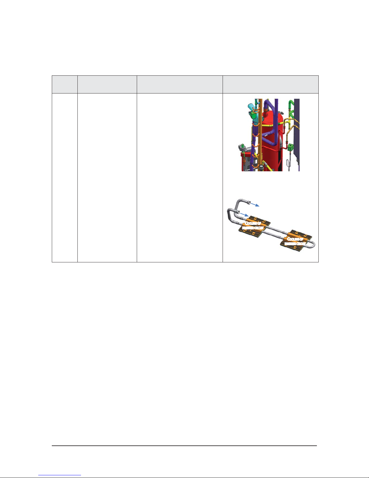
Pipe
Cooling
New Pipe Cooling for cooling
of inverter PCB.
Unapplied
C
OOLING OF
INVERTER CIRCUIT
REFRIGERANT COOLING SYSTEM :
I
T IS COOLING TECHNOLOGY OF INVERTER CIRCUIT THAT USE
REFRIGERATING CYCLE TECHNOLOGY.
C
OOLING OF
INVERTER CIRCUIT
Q
PIPE COOLING
2-8 Samsung Electronics
Changed
part
Changed item
and feature
Basic After changed [HP] After changed [HR]
Tube
struc-
ture
New inverter
cycle technol-
ogy application
New piping
Q
TUBE
Samsung Electronics 2-9
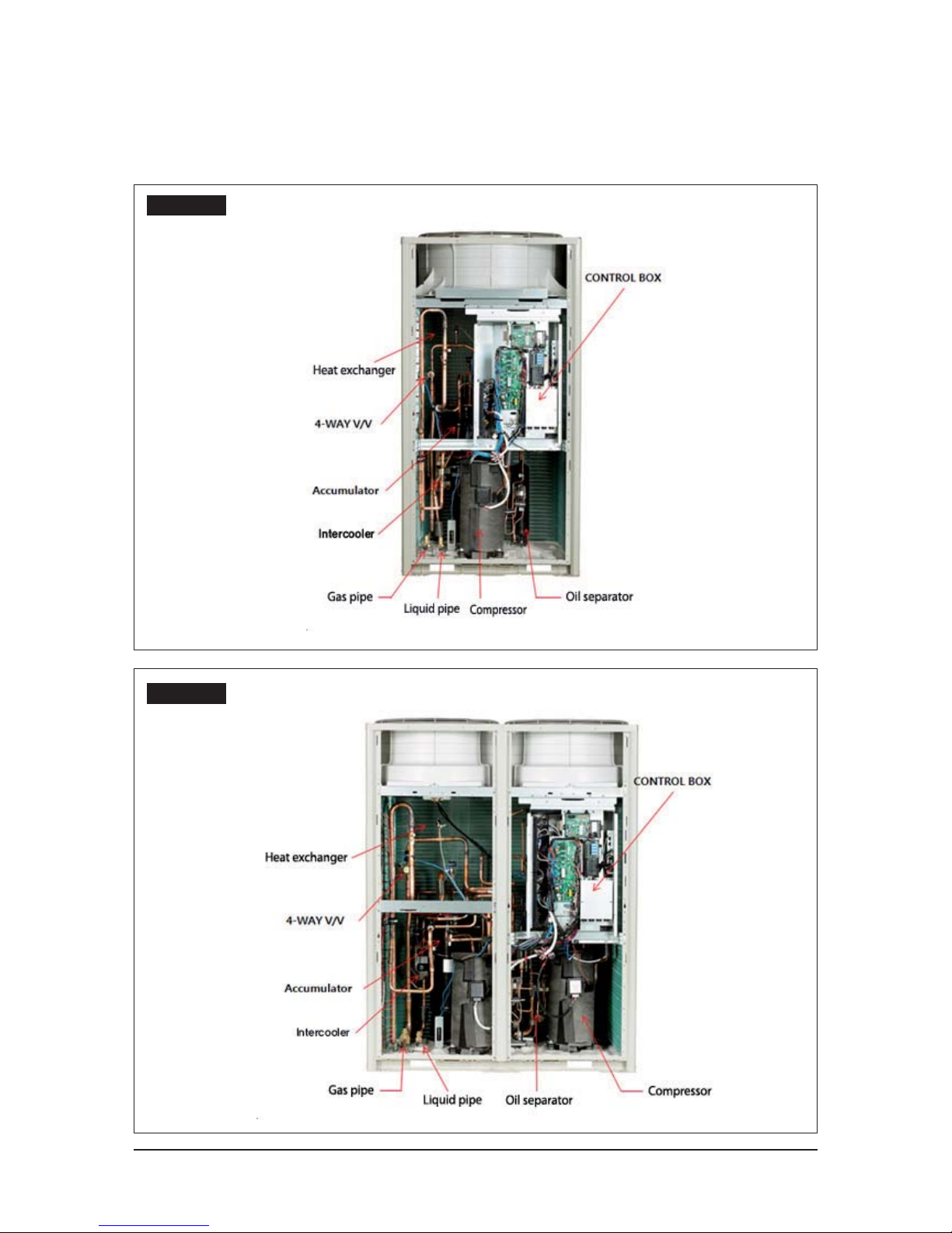
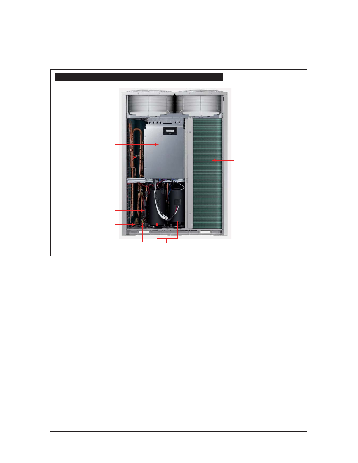
2-1-3 Structure of product ( Heat Pump: AM6666XV66H Series )
Small size
Large size
2-10 Samsung Electronics
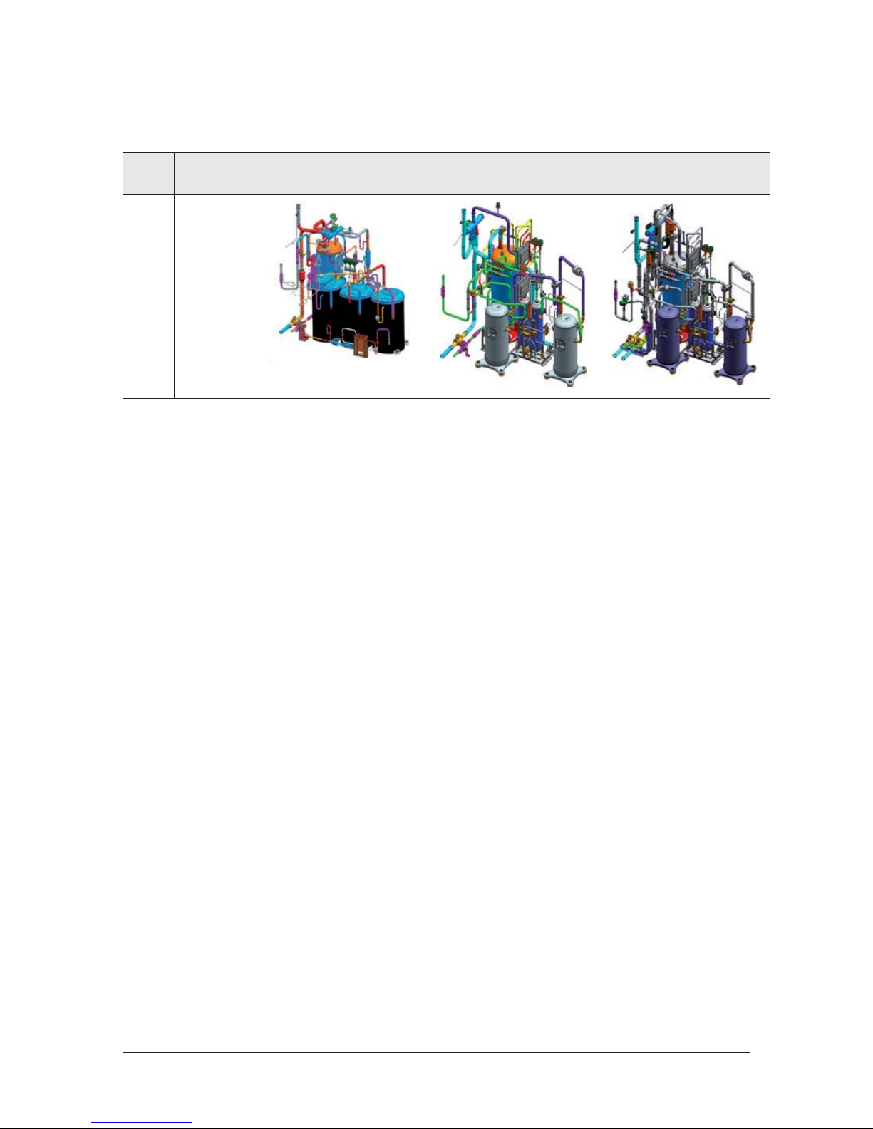
2-1-4 Structure of product (Heat Recovery: AM6666XV66R Series )
Small size
Large size
Heat exchanger
CONTROL BOX
4-WAY V/V
Intercooler
Accumulator
Low Pressure
Gas Pipe
Oil separator
Compressor
High Pressure Gas Pipe
Liquid pipe
Heat exchanger
4-WAY V/V
Accumulator
Intercooler
Low Pressure
Gas Pipe
High Pressure Gas Pipe
Liquid pipe
Compressor
Oil separator
CONTROL BOX
Samsung Electronics 2-11
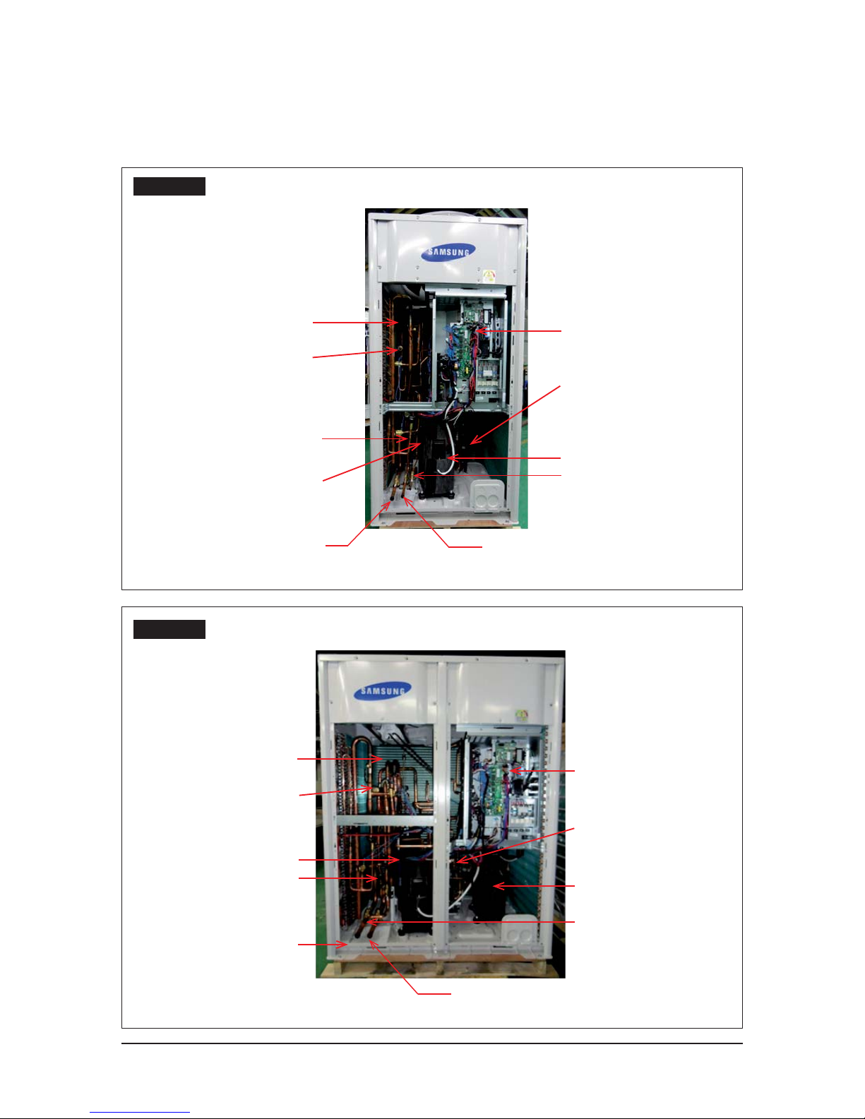
2-1-5 Structure of product (Power supply for 460V, 60Hz, 3Φ : AM6666XV66J6 Series )
Small size
Large size
CONTROL BOX
4-WAY V/V
Oil separator
Heat exchanger
Sub-Cooler
Compressor
CONTROL BOX
4-WAY V/V
Accumulator
Compressor
Oil separator
Heat exchanger
Sub-Cooler
TRANS BOX
TRANS BOX
2-12 Samsung Electronics
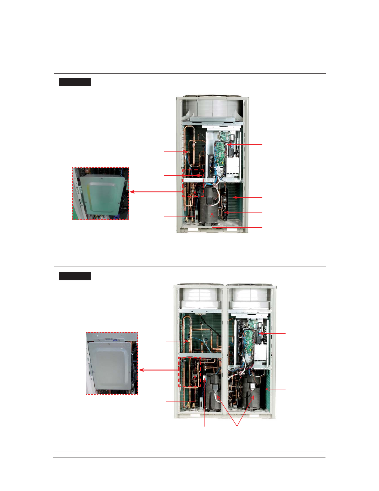
2-1-6 Structure of product (DVM S WATER)
Small size
Large size
Liquid Pipe
4 WAY V/V
Accumulator
CONTROL BOX
Oil separator
Compressor
High pressure Gas Pipe
Low pressure Gas Pipe
Sub Cooler
Plate Heat Exchanger
Receiver
CONTROL BOX
Liquid Pipe
High pressure Gas Pipe
Low pressure Gas Pipe
4 WAY V/V
Receiver
Plate Heat Exchanger
Accumulator
Sub Cooler
Compressor
Oil separator
Samsung Electronics 2-13
2-1-7 Structure of product (Heat Pump AM666KX6 Series)
AM140/160KXVG66, AM140/160/180KXVA66
AM180/200/220KXVG66, AM200/220KXVA66
Control Box
CompressorLiquid V/V
Gas V/V
Subcooler
Accumulator
4-WAY V/V
Heat
Exchanger
Control Box
Control Box
Liquid V/V
Gas V/V
Subcooler
Accumulator
4-WAY V/V
Heat
Exchanger
2-14 Samsung Electronics
Structure of product (Heat Pump AM666KX6 Series)
AM240/260/280KXVG66, AM240/260/280/300KXVA66, AM080KXVS66
Heat Exchanger
Compressor
CONTROL BOX
4-WAY V/V
Subcooler
Gas Pipe
Liquid Pipe

Samsung Electronics 2-15
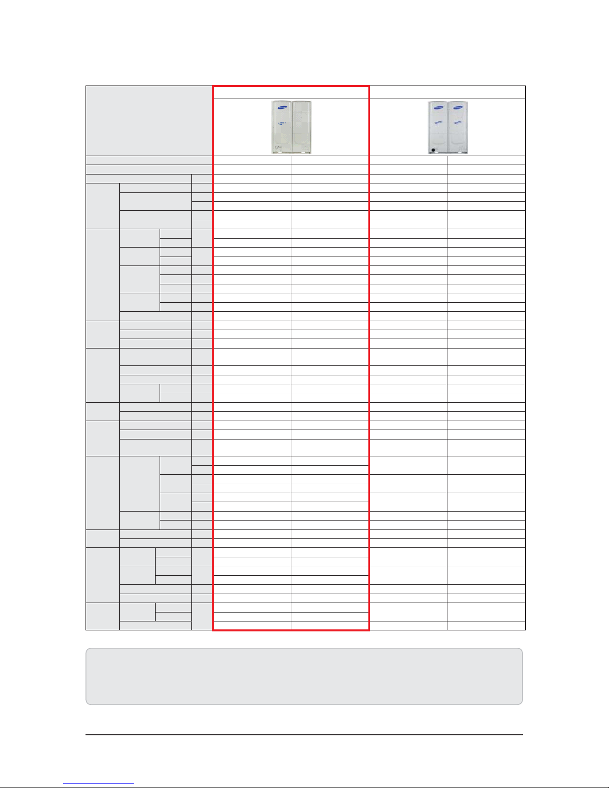
2-2 Product Specifications
2-2-1 Outdoor Unit
TYPE
New Model
Comparative Model
Model AM080FXVAGH AM100FXVAGH AM120FXVAGH RD080HHXG
6
RD100HHXG
6
RD120HHXG
6
Mode HP HP HP HP HP HP
Power Ø,V,Hz 3/AC380~415/50 3/AC380~415/50 3/AC380~415/50 3/AC380~415/50 3/AC380~415/50 3/AC380~415/50
Capacity
Horse Power HP 8 10 12 8 10 12
Cooling
kW 22.4 28.0 33.6 22.4 28.0 33.6
btu/h 76,400 95,500 114,600 76,400 95,500 114,600
Heating
kW 25.2 31.5 37.8 25.2 31.5 37.8
btu/h 86,000 107,500 129,000 86,000 107,500 129,000
Power
Power Input
(Nominal)
Cooling 1)
kW
5.00 6.80 8.40 - - -
Heating 2) 5.10 6.70 8.70 - - -
Current Input
(Nominal)
Cooling 1)
A
8.00 10.90 13.50 - - -
Heating 2) 8.20 10.70 14.00 - - -
Running
Current
Cooling A 8.00 10.90 13.50 8.80 13.00 20.00
Heating A 8.20 10.70 14.00 11.40 12.70 18.40
Max. A 18.00 21.10 25.00 18.40 21.50 28.40
Power
Consumption
Cooling kW 5.00 6.80 8.40 5.20 7.04 9.20
Heating kW 5.10 6.70 8.70 5.46 6.89 8.50
MCA / MFA A 22.5 / 30 29.9 / 40 31.3 / 40 - - -
COP
Nominal Cooling - 4.48 4.12 4.00 - - Nominal Heating - 4.94 4.70 4.34 - - -
ESEER (HP) 7.85 7.25 7.03 - - -
Compressor
Model - DS-GB052FA**** DS-GB066FA**** DS- GB066FA****
ZPJ61KCE-TFD
ZPI61KCE-TFD
ZPJ61KCE-TFD
ZPI61KCE-TFD
ZPJ83KCE-TFD
ZPI83KCE-TFD
Type INV x1 INV x1 INV x1 DVI x1 + FVl x1 DVI x1 + FVl x1 DVI x1 + FVl x1
Output kW 4.70 5.80 5.80 4.36 + 4.36 4.36 + 4.36 5.87 + 5.87
Lubricant
Type - FVC68D FVC68D FVC68D 3MAF POE 3MAF POE 3MAF POE
Charging cc 3,900 3,900 3,900 4,370 4,370 4,370
Refrigerant
Type - R410A R410A R410A R410A R410A R410A
Factory Charging kg 5.5 5.2 5.5 5.0 5.0 5.0
FAN
Type - Propeller + BLDC Propeller + BLDC Propeller + BLDC Propeller + BLDC Propeller + BLDC Propeller + BLDC
Motor Output W 400 400 400 630 630 630
Airow rate
㎥
/min
173 173 210 173 173 210
Pipe
Piping
Connections
Liquid
Ø,mm 9.52 9.52 12.70
9.52 9.52 12.70
Ø,inch 3/8" 3/8" 1/2"
Gas
Ø,mm 19.05 22.22 28.58
19.05 22.22 25.40
Ø,inch 3/4" 7/8" 1 1/8"
Dis. Gas
Ø,mm 15.88 19.05 19.05
---
Ø,inch 5/8" 3/4" 3.4"
Installation
Limitation
Max.Length m 200(220) 200(220) 200(220) 200 200 200
Max.Height m 110(40) 110(40) 110(40) 50(40) 50(40) 50(40)
Cable
Main Power(Below/about20m) mm2 4.0 4.0 4.0 1.5 2.5 4.0
Communication mm2 VCTF 0.75~1.5(2P) VCTF 0.75~1.5(2P) VCTF 0.75~1.5(2P) VCTF 0.75~1.5(2P) VCTF 0.75~1.5(2P) VC TF 0.75~1.5(2P)
Set
Dimension
Net Weight
DVM S HP
kg
190.0 190.0 190.0
237 237 240
DVM S HR 195.0 195.0 195.0
Shipping
Weight
DVM S HP
kg
206.0 206.0 206.0
253 253 256
DVM S HR 211.0 211.0 211.0
Net Dimension(WxHxD) mm 880x1,695x765 880x1,695x765 880x1,695x765 880x1695x765 880x1695x765 880x1695x765
Gross Dimension(WxHxD) mm 948x1,657x832 948x1,657x832 948x1,657x832 948x1912x832 948x1912x832 948x1912x832
Operating
Temp Range
Cooling
DVM S HP
ఁ
-5.0~48.0 -5.0~48.0 -5.0~48.0
-5.0 ~ 48 -5.0 ~ 48.0 -5.0 ~ 48.0
DVM S HR -15.0~48.0 -15.0~48.0 -15.0~48.0
Heating
-20.0~24.0 -20.0~24.0 -20.0~24.0
-20.0 ~ 24.0 -20.0 ~ 24.0 -20.0 ~ 24.0
1. Proper form capacity standard of air conditioning
- Cooling capacity : It is figures that appear in indoor 27˚C DB/19°C WB, outdoor 35˚C DB, length 7.5m of piping, fall 0m standard.
- Heating capacity : It is figures that appear in indoor 20˚C DB, outdoor 7˚C DB, length 7.5m of piping, fall 0m standard.
2. If proper form heating capacity is outdoor temperature 7˚C standard and outdoor temperature goes down by below zero, heating capacity can drop according to temperature condition.
3. Need special load calculation in case of use by main heating in the winter, and please buy product for low temperature that heating effect excels at low temperature.
4. Maximum length between outdoor and indoor units allows up to 200m (Equivalent length 220m).
5. If the indoor unit is below, height length allows up to 110m (If over 50m, decide whether to install the PDM kit). If the outdoor unit is below, allowable height length is 40m.
Product Specications
2-16 Samsung Electronics
TYPE
New Model Comparative Model
Model AM140FXVAGH AM160FX VAGH RD140HHXG
6
RD160HHXG
6
Mode HP HP HP HP
Power Ø,V,Hz 3/AC380~415/50 3/AC380~415/50 3/AC380~415/50 3/AC380~415/50
Capacity
Horse Power HP 14 16 14 16
Capacity
kW 40.0 45.0 39.2 44.8
btu/h 136,000 153,000 133,800 152,900
Heating
kW 45.0 50.0 44.1 50.0
btu/h 153,000 170,000 150,500 172,000
Power
Power Input
(Nominal)
Cooling 1)
kW
8.90 11.00 - -
Heating 2) 9.50 11.50 - -
Current Input
(Nominal)
Cooling 1)
A
14.30 17.60 - -
Heating 2) 15.20 18.40 - -
Running
Current
Cooling A 14.30 17.60 20.90 22.00
Heating A 15.20 18.40 19.40 27.20
Max. A 25.00 32.00 29.40 38.30
Power
Consumption
Cooling kW 8.90 11.00 10.10 12.00
Heating kW 9.50 11.50 9.65 11.30
MCA / MFA A 31.3 / 40 40 / 40 - -
COP
Nominal Cooling - 4.49 4.09 - -
Nominal Heating - 4.74 4.35 - -
ESEER (HP) 7.02 6.78 - -
Compressor
Model - DS-GB066FA**** DS-GB052FA****
ZPJ83KCE-TFD
ZPI83KCE-TFD
ZPJ72KCE-TFD
ZPI72KCE-TFD
Type INV x1 INV x2 DVI x1 + FVl x1 DVI x1 + FVl x2
Output k W 5.80 4.7 x2 5.87 + 5.87 5.16 + 5.16 x2
Lubricant
Type - FVC68D FVC68D 3MAF POE 3MAF POE
Charging cc 3,900 6,200 4,370 6,540
Refrigerant
Type - R410A R410A R410A R410A
Factory Charging kg 7.7 7.4 7.0 7.0
FAN
Type - Propeller + BLDC Propeller + BLDC Propeller + BLDC Propeller + BLDC
Motor Output W 630 x 2 630 x 2 630 x 2 630 x 2
Airflow rate
᎑
ΞΚΟ
226 250 226 250
Pipe
Piping
Connections
Liquid
Ø,mm 12.70 12.70
12.70 12.70
Ø,inch 1/2" 1/2"
Gas
Ø,mm 28.58 28.58
25.40 28.58
Ø,inch 1 1/8" 1 1/8"
Dis. Gas
Ø,mm 19.05 22.22
--
Ø,inch 3/4" 7/8"
Installation
Limitation
Max.Length m 200(220) 200(220) 200 200
Max.Height m 110(40) 110(40) 50(40) 50(40)
Cable
Main Power(Below/about20m) mm2 4.0 6.0 4.0 6.0
Communication mm2 VCTF 0.75~1.5(2P) VCTF 0.75~1.5(2P) VCTF 0.75~1.5(2P) VCTF 0.75~1.5(2P)
Set
Dimension
Net Weight
DVM S HP
kg
235.0 278.0
280 329
DVM S HR 214.0 184.0
Shipping
Weight
DVM S HP
kg
254.0 297.0
301 350
DVM S HR 260.0 303.0
Net Dimension(WxHxD) mm 1295x1695x765 1295x1695x765 1295x1695x765 1295x1695x765
Gross Dimension(WxHxD) mm 1363x1857x832 1363x1857x832 1363x1912x832 1363x1912x832
Operating
Temp Range
Cooling
DVM S HP
ఁ
-5.0~48.0 -5.0~48.0
-5.0 ~ 48.0 -5.0 ~ 48.0
DVM S HR -15.0~48.0 -15.0~48.0
Heating -20.0~24.0 -20.0~24.0 -20.0 ~ 24.0 -20.0 ~ 24.0
Outdoor Unit (cont.)
1. Proper form capacity standard of air conditioning
- Cooling capacity : It is figures that appear in indoor 27˚C DB/19°C WB, outdoor 35˚C DB, length 7.5m of piping, fall 0m standard.
- Heating capacity : It is figures that appear in indoor 20˚C DB, outdoor 7˚C DB, length 7.5m of piping, fall 0m standard.
2. If proper form heating capacity is outdoor temperature 7˚C standard and outdoor temperature goes down by below zero, heating capacity can drop according to temperature condition.
3. Need special load calculation in case of use by main heating in the winter, and please buy product for low temperature that heating effect excels at low temperature.
4. Maximum length between outdoor and indoor units allows up to 200m (Equivalent length 220m).
5. If the indoor unit is below, height length allows up to 110m (If over 50m, decide whether to install the PDM kit). If the outdoor unit is below, allowable height length is 40m.

Product Specications
Samsung Electronics 2-17
Outdoor Unit (cont.)
TYPE
New Model Comparative Model
Model AM180FXVAGH AM200FXVAGH AM220FXVAGH RD180HHXG
6
RD200HHXG
6
Mode HP HP HP HP HP
Power Ø,V,Hz 3/AC380~415/50 3/AC380~415/50 3/AC380~415/50 3/AC380~415/50 3/AC380~415/50
Capacity
Horse Power HP 18 2 0 22 18 20
Cooling
kW 50.4 56.0 61.6 50.4 56.0
btu/h 171,900 191,000 210,000 171,900 191,000
Heating
kW 56.7 63.0 69.3 56.7 63.0
btu/h 193,500 215,000 236,000 193,500 215,000
Power
Power Input
(Nominal)
Cooling 1)
kW
12.80 15.19 17.35 - -
Heating 2) 11.90 13.90 16.70 - -
Current Input
(Nominal)
Cooling 1)
A
20.70 24.40 27.80 - -
Heating 2) 19.10 22.30 26.80 - -
Running
Current
Cooling A 20.70 24.40 27.80 31.30 32.80
Heating A 19.10 22.30 26.80 26.70 29.10
Max. A 39.10 42.50 44.50 42.50 44.10
Power
Consumption
Cooling kW 12.88 15.19 17.35 15.70 17.00
Heating kW 11.90 13.90 16.70 12.90 14.50
MCA / MFA A 48.9 / 50 52.5 / 75 52.5 / 75 - -
COP
Nominal Cooling - 3.91 3.69 3.55 - Nominal Heating - 4.76 4.53 4.15 - -
ESEER (HP) 6.59 6.56 6.25 - -
Compressor
Model - DS-GB066FA**** DS-GB066FA**** DS- GB066FA****
ZPJ83KCE-TFD
ZPI83KCE-TFD
ZPJ83KCE-TFD
ZPI83KCE-TFD
Type INV x2 INV x2 INV x2 DVI x1 + FVl x2 DVI x1 + FVl x2
Output kW 5.8 x2 5.8 x2 5.8 x2 5.87 + 5.87 x2 5.87 + 5.87 x2
Lubricant
Type - FVC68D FVC68D 3MAF POE 3MAF POE
Charging cc 6,200 6,200 6,200 6,540 6,540
Refrigerant
Type - R410A R410A R410A R410A R410A
Factory Charging kg 8 .7 8.4 8. 4 8 .5 8.5
FAN
Type - Propeller + BLDC Propeller + BLDC Propeller + BLDC Propeller + BLDC Propeller + BLDC
Motor Output W 630 x2 630 x2 630 x2 630 x2 630 x2
Airflow rate
᎑ ΞΚΟ
270 275 280 270 275
Pipe
Piping
Connections
Liquid
Ø,mm 15.88 15.88 15.88
15.88 15.88
Ø,inch 5/8" 5/8" 5/8"
Gas
Ø,mm 28.58 28.58 28.58
28.58 28.58
Ø,inch 1 1/8" 1 1/8" 1 1/8"
Dis. Gas
Ø,mm 22.22 28.58 28.58
--
Ø,inch 7/8" 1 1/8" 1 1/8"
Installation
Limitation
Max.Length m 200(220) 200(220) 200(220) 200 200
Max.Height m 110(40) 110(40) 110(40) 50(40) 50(40)
Cable
Main Power(Below/about20m) mm2 10.0 10.0 10.0 6.0 10.0
Communication mm2 VCT F 0.75~1.5(2P) VCTF 0.75~1.5(2P) VCTF 0.75~1.5(2P) VC TF 0.75~1.5(2P) VCTF 0.75~1.5(2P)
Set
Dimension
Net Weight
DVM S HP
kg
300.0 300.0 300.0
340.0 349.0
DVM S HR 306.0 306.0 306.0
Shipping
Weight
DVM S HP
kg
319.0 319.0 319.0
361.0 370.0
DVM S HR 325.0 325.0 325.0
Net Dimension(WxHxD) mm 1295x1695x765 1295x1695x765 1295x1695x765 1295x1695x765 1295x1695x765
Gross Dimension(WxHxD) mm 1363x1857x832 1363x1857x832 1363x1857x832 1363x1912x832 1363x1912x832
Operating
Temp Range
Cooling
DVM S HP
ఁ
-5.0 ~ 48.0 -5.0 ~ 48.0 -5.0 ~ 48.0
-5.0~ 48.0 -5.0 ~ 48.0
DVM S HR -15.0~48.0 -15.0~48.0 -15.0~48.0
Heating -20.0 ~ 24.0 -20.0 ~ 24.0 -20.0 ~ 24.0 -20.0 ~ 24.0 -20.0 ~ 24.0
1. Proper form capacity standard of air conditioning
- Cooling capacity : It is figures that appear in indoor 27˚C DB/19°C WB, outdoor 35˚C DB, length 7.5m of piping, fall 0m standard.
- Heating capacity : It is figures that appear in indoor 20˚C DB, outdoor 7˚C DB, length 7.5m of piping, fall 0m standard.
2. If proper form heating capacity is outdoor temperature 7˚C standard and outdoor temperature goes down by below zero, heating capacity can drop according to temperature condition.
3. Need special load calculation in case of use by main heating in the winter, and please buy product for low temperature that heating effect excels at low temperature.
4. Maximum length between outdoor and indoor units allows up to 200m (Equivalent length 220m).
5. If the indoor unit is below, height length allows up to 110m (If over 50m, decide whether to install the PDM kit). If the outdoor unit is below, allowable height length is 40m.

Product Specications
2-18 Samsung Electronics
TYPE
New Model Comparative Model
Model AM080FX VAGR AM100FXVAGR AM120FXVAGR RD080HRXG
6
RD100HRXG
6
RD120HRXG
6
Mode HR HR HR HR HR HR
Power Ø,V,Hz 3/AC380~415/50 3/A C380~415/50 3/AC380~415/50 3/AC380~415/50 3/AC380~415/50 3/AC380~415/50
Capacity
Horse Power HP 8 10 12 8 10 12
Capacity
kW 22.4 28.0 33.6 22.4 28.0 33.6
btu/h 76,400 95,500 114,600 76,400 95,500 114,600
Heating
kW 25.2 31.5 37.8 25.2 31.5 37.8
btu/h 86,000 107,500 129,000 86,000 107,500 129,000
Power
Power Input
(Nominal)
Cooling 1)
kW
5.00 6.80 8.40 - - -
Heating 2) 5.10 6.70 8.70 - - -
Current Input
(Nominal)
Cooling 1)
A
8.00 10.90 13.50 - - -
Heating 2) 8.20 10.70 14.00 - - -
Running
Current
Cooling A 8.00 10.90 13.50 8.80 13.00 20.00
Heating A 8.20 10.70 14.00 11.40 12.70 18.40
Max. A 18.00 21.10 25.00 18.40 21.50 28.40
Power
Consumption
Cooling kW 5.00 6.80 8.40 5.20 7.04 9.20
Heating kW 5.10 6.70 8.70 5.46 6.89 8.50
MCA / MFA A 22.5 / 30 29.9 / 40 31.3 / 40 - - -
COP
Nominal Cooling - 4.48 4.12 4.00 - - Nominal Heating - 4.94 4.70 4.34 - - -
ESEER (HP) 7.85 7.25 7.03 - - -
Compressor
Model - DS-GB052FA**** DS -GB066FA**** DS-GB066FA****
ZPJ61KCE-TFD
ZPI61KCE-TFD
ZPJ61KCE-TFD
ZPI61KCE-TFD
ZPJ83KCE-TFD
ZPI83KCE-TFD
Type INV x1 INV x1 INV x1 DVI x1 + FVl x1 DVI x1 + FVl x1 DVI x1 + FVl x1
Output kW 4.70 5.80 5.80 4.36 + 4.36 4.36 + 4.36 5.87 + 5.87
Lubricant
Type - FVC68D
FVC68D FVC68D 3MAF POE 3MAF PO E 3MAF POE
Charging cc 3,900 3,900 3,900 4,370 4,370 4,370
Refrigerant
Type - R410A R410A R410A R410A R410A R410A
Factory Charging kg 5.5 5.2 5.5 5.0 5.0 5.0
FAN
Type - Propeller + BLDC Propeller + BLDC Propeller + BLDC Propeller + BLDC Propeller + BLDC Propeller + BLDC
Motor Output W 400 40 0 400 630 6 30 630
Airflow rate
᎑ ΞΚΟ
173 173 210 173 17 3 210
Pipe
Piping
Connections
Liquid
Ø,mm 9.52 9.52 12.70
9.52 9.52 12.70
Ø,inch 3/8" 3/8" 1/2"
Gas
Ø,mm 19.05 22.22 28.58
19.05 22.22 25.40
Ø,inch 3/4" 7/8" 1 1/8"
Dis. Gas
Ø,mm 15.88 19.05 19.05
15.88 19.05 22.22
Ø,inch 5/8" 3/4" 3.4"
Installation
Limitation
Max.Length m 200(220) 200(220) 200(220) 200 200 200
Max.Height m 110(40) 110(40) 110(40) 50(40) 50(40) 50(40)
Cable
Main Power(Below/about20m) mm2 4.0 4.0 4.0 1.5 2.5 4.0
Communication mm2 VC TF 0.75~1.5(2P) VCT F 0.75~1.5(2P) VCTF 0.75~1.5(2P) VCTF 0.75~1.5(2P) VC TF 0.75~1.5(2P) VCTF 0.75~1.5(2P)
Set
Dimension
Net Weight
DVM S HP
kg
190.0 190.0 190.0
243 243 243
DVM S HR 195.0 195.0 195.0
Shipping
Weight
DVM S HP
kg
206.0 206.0 206.0
259 259 259
DVM S HR 211.0 211.0 211.0
Net Dimension(WxHxD) mm 880x1,695x765 880x1,695x765 880x1,695x765 880x1695x765 880x1695x765 880x1695x765
Gross Dimension(WxHxD) mm 948x1,657x832 948x1,657x832 948x1,657x832 948x1912x832 948x1912x832 948x1912x832
Operating
Temp Range
Cooling
DVM S HP
ఁ
-5.0~48.0 -5.0~48.0 -5.0~48.0
-5.0 ~ 48.0 -5.0 ~ 48.0 -5.0 ~ 48.0
DVM S HR -15.0~48.0 -15.0~48.0 -15.0~48.0
Heating -20.0~24.0 -20.0~24.0 -20.0~24.0 -20.0 ~ 24.0 -20.0 ~ 24.0 -20 .0~ 24.0
Outdoor Unit (cont.)
1. Proper form capacity standard of air conditioning
- Cooling capacity : It is figures that appear in indoor 27˚C DB/19°C WB, outdoor 35˚C DB, length 7.5m of piping, fall 0m standard.
- Heating capacity : It is figures that appear in indoor 20˚C DB, outdoor 7˚C DB, length 7.5m of piping, fall 0m standard.
2. If proper form heating capacity is outdoor temperature 7˚C standard and outdoor temperature goes down by below zero, heating capacity can drop according to temperature condition.
3. Need special load calculation in case of use by main heating in the winter, and please buy product for low temperature that heating effect excels at low temperature.
4. Maximum length between outdoor and indoor units allows up to 200m (Equivalent length 220m).
5. If the indoor unit is below, height length allows up to 110m (If over 50m, decide whether to install the PDM kit). If the outdoor unit is below, allowable height length is 40m.
Product Specications
Samsung Electronics 2-19
TYPE
New Model Comparative Model
Model AM140FXVAGR AM160FXVAGR RD140HRXG
6
RD160HRXG
6
Mode HR HR HR HR
Power Ø,V,Hz 3/AC380~415/50 3/AC380~415/50 3/AC380~415/50 3/AC380~415/50
Capacity
Horse Power HP 14 16 14 16
Capacity
kW 40.0 45.0 39.2 44.8
btu/h 136,000 153,000 133,800 152,900
Heating
kW 45.0 50.0 44.1 50.0
btu/h 153,000 170,000 150,500 172,000
Power
Power Input
(Nominal)
Cooling 1)
kW
8.90 11.00 - -
Heating 2) 9.50 11.50 - -
Current Input
(Nominal)
Cooling 1)
A
14.30 17.60 - -
Heating 2) 15.20 18.40 - -
Running
Current
Cooling A 14.30 17.60 20.90 22.00
Heating A 15.20 18.40 19.40 27.20
Max. A 25.00 32.00 29.40 38.30
Power
Consumption
Cooling kW 8.90 11.00 10.10 12.00
Heating kW 9.50 11.50 9.65 11.30
MCA / MFA A 31.3 / 40 40 / 40 - -
COP
Nominal Cooling - 4.49 4.09 - Nominal Heating - 4.74 4.35 - -
ESEER (HP) 7.02 6.78 - -
Compressor
Model - DS-GB066FA**** DS-GB052FA****
ZPJ83KCE-TFD
ZPI83KCE-TFD
ZPJ72KCE-TFD
ZPI72KCE-TFD
Type INV x1 INV x2 DVI x1 + FVl x1 DVI x1 + FVl x2
Output kW 5.80 4.7 x2 5.87 + 5.87 5.16 + 5.16 x2
Lubricant
Type - FVC68D FVC68D 3MAF POE 3MAF POE
Charging cc 3,900 6,200 4,370 6,540
Refrigerant
Type - R410A R410A R410A R410A
Factory Charging kg 7.7 7.4 7.0 7.0
FAN
Type - Propeller + BLDC Propeller + BLDC Propeller + BLDC Propeller + BLDC
Motor Output W 630 x 2 630 x 2 630 x 2 630 x 2
Airflow rate
᎑ ΞΚΟ
226 250 226 250
Pipe
Piping
Connections
Liquid
Ø,mm 12.70 12.70
12.70 12.70
Ø,inch 1/2" 1/2"
Gas
Ø,mm 28.58 28.58
25.40 28.58
Ø,inch 1 1/8" 1 1/8"
Dis. Gas
Ø,mm 19.05 22.22
22.22 25.40
Ø,inch 3/4" 7/8"
Installation
Limitation
Max.Length m 200(220) 200(220) 200 200
Max.Height m 110(40) 110(40) 50(40) 50(40)
Cable
Main Power(Below/
about20m)
mm2 4.0 6.0 4.0 6.0
Communication mm2 VCTF 0.75~1.5(2P) VCTF 0.75~1.5(2P) VCTF 0.75~1.5(2P) VCTF 0.75~1.5(2P)
Set
Dimension
Net Weight
DVM S HP
kg
235.0 278.0
293 338
DVM S HR 214.0 184.0
Shipping
Weight
DVM S HP
kg
254.0 297.0
314 359
DVM S HR 260.0 303.0
Net Dimension(WxHxD) mm 1295x1695x765 1295x1695x765
1295x1695x765 1295x1695x765
Gross Dimension(WxHxD) mm 1363x1857x832 1363x1857x832
1363x1912x832 1363x1912x832
Operating
Temp Range
Cooling
DVM S HP
ఁ
-5.0~48.0 -5.0~48.0
-5 .0~ 48.0 -5.0~ 48.0
DVM S HR -15.0~48.0 -15.0~48.0
Heating -20.0~24.0 -20.0~24.0
-20.0~ 24.0 -20.0~ 24.0
Outdoor Unit (cont.)
1. Proper form capacity standard of air conditioning
- Cooling capacity : It is figures that appear in indoor 27˚C DB/19°C WB, outdoor 35˚C DB, length 7.5m of piping, fall 0m standard.
- Heating capacity : It is figures that appear in indoor 20˚C DB, outdoor 7˚C DB, length 7.5m of piping, fall 0m standard.
2. If proper form heating capacity is outdoor temperature 7˚C standard and outdoor temperature goes down by below zero, heating capacity can drop according to temperature condition.
3. Need special load calculation in case of use by main heating in the winter, and please buy product for low temperature that heating effect excels at low temperature.
4. Maximum length between outdoor and indoor units allows up to 200m (Equivalent length 220m).
5. If the indoor unit is below, height length allows up to 110m (If over 50m, decide whether to install the PDM kit). If the outdoor unit is below, allowable height length is 40m.

Product Specications
2-20 Samsung Electronics
TYPE
New Model Comparative Model
Model AM180FXVAGR AM200FXVAGR AM220FX VAGR RD180HRXG
6
RD200HRXG
6
Mode HR HR HR HR HR
Power Ø,V,Hz 3/AC380~415/50 3/AC380~415/50 3/AC380~415/50 3/AC380~415/50 3/AC380~415/50
Capacity
Horse Power HP 18 20 22 18 20
Capacity
kW 50.4 56.0 61.6 50.4 56.0
btu/h 171,900 191,000 210,000 171,900 191,000
Heating
kW 56.7 63.0 69.3 56.7 63.0
btu/h 193,500 215,000 236,000 193,500 215,000
Power
Power Input
(Nominal)
Cooling 1)
kW
12.80 15.19 17.35 - -
Heating 2) 11.90 13.90 16.70 - -
Current Input
(Nominal)
Cooling 1)
A
20.70 24.40 27.80 - -
Heating 2) 19.10 22.30 26.80 - -
Running
Current
Cooling A 20.70 24.40 27.80 31.30 32.80
Heating A 19.10 22.30 26.80 26.70 29.10
Max. A 39.10 42.50 44.50 42.50 44.10
Power
Consumption
Cooling kW 12.88 15.19 17.35 15.70 17.00
Heating kW 11.90 13.90 16.70 12.90 14.50
MCA / MFA A 48.9 / 50 52.5 / 75 52.5 / 75 - -
COP
Nominal Cooling - 3.91 3.69 3.55 - Nominal Heating - 4.76 4.53 4.15 - -
ESEER (HP) 6.59 6.56 6.25 - -
Compressor
Model - DS-GB066FA**** DS-GB066FA**** DS- GB066FA****
ZPJ83KCE-TFD
ZPI83KCE-TFD
ZPJ83KCE-TFD
ZPI83KCE-TFD
Type INV x2 INV x2 INV x2 DVI x1 + FVl x2 DVI x1 + FVl x2
Output kW 5.8 x2 5.8 x2 5.8 x2 5.87 + 5.87 x2 5.87 + 5.87 x2
Lubricant
Type - FVC68D FVC68D 3MAF POE 3MAF POE
Charging cc 6,200 6,200 6,200 6,540 6,540
Refrigerant
Type - R410A R410A R410A R410A R410A
Factory Charging kg 8.7 8.4 8.4 8.5 8.5
FAN
Type - Propeller + BLDC Propeller + BLDC Propeller + BLDC Propeller + BLDC Propeller + BLDC
Motor Output W 630 x2 630 x2 630 x2 630 x2 630 x2
Airflow rate
᎑ ΞΚΟ
270 275 280 270 275
Pipe
Piping
Connections
Liquid
Ø,mm
15.88 15.88 15.88
15.88 15.88
Ø,inch
5/8" 5/8" 5/8"
Gas
Ø,mm
28.58 28.58 28.58
28.58 28.58
Ø,inch
1 1/8" 1 1/8" 1 1/8"
Dis. Gas
Ø,mm
22.22 28.58 28.58
28.58 28.58
Ø,inch
7/8" 1 1/8" 1 1/8"
Installation
Limitation
Max.Length m
200(220) 200(220) 200(220)
200 200
Max.Height m
110(40) 110(40) 110(40)
50(40) 50(40)
Cable
Main Power(Below/
about20m)
mm2 10.0 10.0 10.0 6.0 10.0
Communication mm2 VCTF 0.75~1.5(2P) VC TF 0.75~1.5(2P) VCTF 0.75~1.5(2P) VCTF 0.75~1.5(2P) VCTF 0.75~1.5(2P)
Set
Dimension
Net Weight
DVM S HP
kg
300.0 300.0 300.0
349 355
DVM S HR 306.0 306.0 306.0
Shipping
Weight
DVM S HP
kg
319.0 319.0 319.0
369 376
DVM S HR 325.0 325.0 325.0
Net Dimension(WxHxD) mm 1295x1695x765 1295x1695x765 1295x1695x765
1295x1695x765 1295x1695x765
Gross Dimension(WxHxD) mm 1363x1857x832 1363x1857x832 1363x1857x832
1363x1912x832 1363x1912x832
Operating
Temp Range
Cooling
DVM S HP
ఁ
-5.0 ~ 48.0 -5.0 ~ 48.0 -5.0 ~ 48.0
-5.0 ~ 48.0 -5.0 ~ 48.0
DVM S HR -15.0~48.0 -15.0~48.0 -15.0~48.0
Heating -20.0 ~ 24.0 -20.0 ~ 24.0 -20.0 ~ 24.0
-20.0 ~ 24.0 -20.0~ 24.0
Outdoor Unit (cont.)
1. Proper form capacity standard of air conditioning
- Cooling capacity : It is figures that appear in indoor 27˚C DB/19°C WB, outdoor 35˚C DB, length 7.5m of piping, fall 0m standard.
- Heating capacity : It is figures that appear in indoor 20˚C DB, outdoor 7˚C DB, length 7.5m of piping, fall 0m standard.
2. If proper form heating capacity is outdoor temperature 7˚C standard and outdoor temperature goes down by below zero, heating capacity can drop according to temperature condition.
3. Need special load calculation in case of use by main heating in the winter, and please buy product for low temperature that heating effect excels at low temperature.
4. Maximum length between outdoor and indoor units allows up to 200m (Equivalent length 220m).
5. If the indoor unit is below, height length allows up to 110m (If over 50m, decide whether to install the PDM kit). If the outdoor unit is below, allowable height length is 40m.

Product Specications
2-21 Samsung Electronics Samsung Electronics 2-22
Outdoor Unit (cont.)
1. Proper form capacity standard of air conditioning
- Cooling capacity : It is figures that appear in indoor 27˚C DB/19°C WB, outdoor 35˚C DB, length 7.5m of piping, fall 0m standard.
- Heating capacity : It is figures that appear in indoor 20˚C DB, outdoor 7˚C DB, length 7.5m of piping, fall 0m standard.
2. If proper form heating capacity is outdoor temperature 7˚C standard and outdoor temperature goes down by below zero, heating capacity can drop according to temperature condition.
3. Need special load calculation in case of use by main heating in the winter, and please buy product for low temperature that heating effect excels at low temperature.
4. Maximum length between outdoor and indoor units allows up to 200m (Equivalent length 220m).
5. If the indoor unit is below, height length allows up to 110m (If over 50m, decide whether to install the PDM kit). If the outdoor unit is below, allowable height length is 40m.
TYPE
New Model Comparative Model
Model Name AM080FXWANR/EU AM100FXWANR/EU AM120FXWANR/EU AM200FXWANR/EU RD100DRXH1 RD200DRXH1 RD300DRXH1
Power Supply Φ, #, V, Hz 3/AC380~415/50 3/AC380~415/50
Performance
HP HP 8 10 12 20 10 20 30
Capacity
(Nominal)
Cooling
kW 23 29 34.8 58 29 58 87
kcal/h 19780 24940 29928 49880 24940 49880 74820
Heating
kW 26 32.6 39.2 65.2 32.6 65.2 97.9
kcal/h 22360 28036 33712 56072 28036 56072 84194
Power
Power Input
(Nominal)
Cooling
kW
4.18 5.58 6.69 11.15 5.8 11.6 17.4
Heating 4.33 5.62 6.76 11.24 5.69 11.8 17.8
Current Input
(Nominal)
Cooling
A
7.0 9.4 11.3 18.8 10.5 21.4 31.9
Heating 7.3 9.5 11.4 19.0 9.5 20.9 31.1
MFA - 20 20 30 40 20 40 60
COP
Nominal Cooling 1) - 5.50 5.20 5.20 5.20 - - -
Nominal Heating 2) - 6.00 5.80 5.80 5.80 - - -
Compressor
Type SSC Scroll x 1 SSC Scroll x 1 SSC Scroll x 1 SSC Scroll x 2 DVI Scrollx1 DVI Scrollx1 + FVI Scrollx1 DVI Scroll + FVI Scrollx2
Output kW 4.96 4.96 6.13 4.96 x 2 7.04 7.48 + 7.43 7.48 + (7.43 x 2)
Oil
Type - PVE PVE PVE PVE 3MAF POE 3MAF POE 3MAF POE
Initial Charge Liter 3.9 3.9 3.9 6.2 2.185 4.37 6.555
Condenser
Type -
Stainless steel
plate
Stainless steel
plate
Stainless steel
plate
Stainless steel
plate
Stainless steel
plate
Stainless steel
plate
Stainless steel
plate
Pipe Size Φ, inch(A) PT1-1/4 (32) PT1-1/4 (32) PT1-1/4 (32) PT1-1/4 (32) 1 1/4" (32A) 1 1/4" (32A) 2 (50A)
Lost Head
kPa22304354305454
Water Flow Rate
LPM 80 96 114 190 96 190 285
Max. Pressure
MPa 1.96 1.96 1.96 1.96 1.96 1.96 1.96
Piping
Connections
Liquid Pipe Φ, mm 9.52 9.52 12.7 15.88 9.52 15.88 19.05
Gas Pipe Φ, mm 19.05 22.23 25.4 28.58 22.23 28.58 31.75
Discharge Gas Pipe Φ, mm 15.88 19.05 22.23 25.4 19.05 25.4 28.58
Oil Equalizing Pipe Φ, mm -----6.35 6.35
Installation
Limitation
Airow rate
Max. Length m 170 170 170 170 150 150 150
Max. Height m 50 50 50 50 50(40) 50(40) 50(40)
Field
Wiring
Power Source Wire mm2 2.50 2.50 4.00 6.00 1.5 4.0 10.0
Transmission Cable mm2 0.75~1.25 0.75~1.25 0.75~1.25 0.75~1.25 0.75~1.5 0.75~1.5 0.75~1.5
Refrigerant
Type -
R410A R410A R410A R410A R410A R410A R410A
Factory Charging kg
5.5 5.8 6.0 9.8 5.8 9.4 12.0
External
Dimension
Net Weight
kg
160 160 160 240 160 235 320
Shipping Weight 167 167 167 250 167 242 330
Net Dimensions (WxHxD)
kg
770x1000x545 770x1000x545 770x1000x545 1100x1000x545 770 x 1,117 x 545 770 x 1,117 x 545 1,100 x 1,117 x 550
Shipping Dimensions
(WxHxD)
840x1200x620 840x1200x620 840x1200x620 1170x1200x620 840 x 1,287 x 620 840 x 1,287 x 620 1,170 x 1,170 x 620
Operating
Temp.
Range(Water)
Cooling
ఁ
10~45 10~45 10~45 10~45 10~45 10~45 10~45
Heating
ఁ
10~45 10~45 10~45 10~45 10~45 10~45 10~45

2-23 Samsung Electronics
TYPE
New Model
Model AM240HXVAGH AM260HXVAGH
Mode HP HP
Power Φ, V, Hz 3/AC380~415/50
Capacity
Horse Power HP 24 26
Cooling
kW 67.2 72.8
btu/h - -
Heating
kW 75.6 81.9
btu/h - -
Power
Power input
(Nominal)
Cooling 1)
kW
17.10 19.30
Heating 2) 19.80 21.80
Current Input
(Nominal)
Cooling 1)
A
26.83 30.28
Heating 2) 31.06 34.20
Running
Current"
Cooling A 26.83 30.28
Heating A 31.06 34.20
Max A 55 58
Power
Consumption
Cooling kW 26.83 30.28
Heating kW 31.06 34.20
MCA/MFA A 60.5/75 63.8/75
COP Nominal Cooling - 3.930 3.772
Nominal Heating - 3.818 3.757
ESEER (HP) - - -
Compressor Model - DS-GB066FA* DS-GB070FA*
Type INV x 2EA INV x 2EA
Output kW - -
Lubricant
Type - FVC68D FVC68D
Charging cc 6,200 6,200
Refrigerant Type - R410A R410A
Factory Charging kg 14.3 14.3
Fan Type - Propeller + BLDC Propeller + BLDC
Motor Output W 620 x 2 620 x 2
Airflow rate
᎑ ΞΚΟ
310 310
Piping
Connections
Liquid pipe
Φ, mm 15.88 19.05
Φ, inch 5/8" 3/4"
Gas pipe
Φ, mm 34.92 34.92
Φ, inch 1 3/8" 1 3/8"
High pressure gas pipe
Φ, mm - -
Φ, inch
Installation
Limitation
Max. Length m 200(220) 200(220)
Max. Height m 110.0(40.0) 110.0(40.0)
Cable Main Power(Below 20m) mm2 16 16
Communication mm2 VCTF 0.75 ~ 1.5(2P) VCTF 0.75 ~ 1.5(2P)
Set
Dimension
Net weight kg 360 360
Gross weight kg 370 370
Net dimension (WxHxD) mm 1,295 x 1,695 x 765 1,295 x 1,695 x 765
Gross dimension (WxHxD) mm
1,363 x 1,887 x 832 1,363 x 1,887 x 832
Operating Temp. Range
Cooling
ఁ
-5.0 ~ 48.0 -5.0 ~ 48.0
Heating
ఁ
-25.0 ~ 24.0 -25.0 ~ 24.0
Outdoor Unit (cont.)
1. Proper form capacity standard of air conditioning
- Cooling capacity : It is figures that appear in indoor 27˚C DB/19°C WB, outdoor 35˚C DB, length 7.5m of piping, fall 0m standard.
- Heating capacity : It is figures that appear in indoor 20˚C DB, outdoor 7˚C DB, length 7.5m of piping, fall 0m standard.
2. If proper form heating capacity is outdoor temperature 7˚C standard and outdoor temperature goes down by below zero, heating capacity can drop according to temperature condition.
3. Need special load calculation in case of use by main heating in the winter, and please buy product for low temperature that heating effect excels at low temperature.
4. Maximum length between outdoor and indoor units allows up to 200m (Equivalent length 220m).
5. If the indoor unit is below, height length allows up to 110m (If over 50m, decide whether to install the PDM kit). If the outdoor unit is below, allowable height length is 40m.
2-24 Samsung Electronics Samsung Electronics 2-25
Outdoor Unit (cont.)
1. Proper form capacity standard of air conditioning
- Cooling capacity : It is figures that appear in indoor 27˚C DB/19°C WB, outdoor 35˚C DB, length 7.5m of piping, fall 0m standard.
- Heating capacity : It is figures that appear in indoor 20˚C DB, outdoor 7˚C DB, length 7.5m of piping, fall 0m standard.
2. If proper form heating capacity is outdoor temperature 7˚C standard and outdoor temperature goes down by below zero, heating capacity can drop according to temperature condition.
3. Need special load calculation in case of use by main heating in the winter, and please buy product for low temperature that heating effect excels at low temperature.
4. Maximum length between outdoor and indoor units allows up to 200m (Equivalent length 220m).
5. If the indoor unit is below, height length allows up to 110m (If over 50m, decide whether to install the PDM kit). If the outdoor unit is below, allowable height length is 40m.
TYPE
New Model New Model
Model
AM080JXVAGH AM100JX VAGH AM120JXVAGH AM140JXVAGH AM160JXVAGH AM180JXVAGH AM200JXVAGH AM220JXVAGH
Mode
HP HP HP HP HP HP HP HP
Power Φ, V, Hz
3/AC380-415/50 3/AC380-415/50 3/AC380-415/50 3/AC380-415/50 3/AC380-415/50 3/AC380-415/50 3/AC380-415/50 3/AC380-415/50
Capacity
Horse Power HP
8 10121416182022
Cooling kW
22.4 28.0 33.6 40.0 45.0 50.4 56.0 61.6
Heating kW
25.2 31.5 37.8 45.0 50.4 56.7 63.0 69.3
Power
Power input
(Nominal)
Cooling 1)
kW
5.00 6.85 8.16 10.93 11.98 12.45 14.59 17.35
Heating 2)
5.10 6.65 8.03 10.15 11.60 11.90 13.90 16.70
Current Input
(Nominal)
Cooling 1)
A
8.00 11.00 13.10 17.50 19.20 20.00 13.90 27.80
Heating 2)
8.20 10.70 12.90 16.30 18.60 19.10 23.40 26.80
Running
Current"
Cooling A
8.00 11.00 13.10 17.50 19.20 20.00 13.90 27.80
Heating A
8.20 10.70 12.90 16.30 18.60 19.10 23.40 26.80
Max A
18.0 21.1 25.0 25.0 32.0 39.1 22.30 44.5
Power
Consumption
Cooling kW
5.00 6.85 8.16 10.93 11.98 12.45 14.59 17.35
Heating kW
5.10 6.65 8.03 10.15 11.60 11.90 13.90 16.70
MCA/MFA A
22.5/30 29.9/40 31.3/40 31.3/40 40.0/40 48.9/50 52.5/75 55.6/75
COP
Nominal Cooling -
4.480 4.090 4.120 3.660 3.760 4.050 3.840 3.550
Nominal Heating -
4.940 4.740 4.710 4.430 4.340 4.760 4.530 4.150
ESEER (HP) -
--------
Compressor
Model -
DS-GA046FA* DS-GB066FA* DS-GB066FA* DS-GB066FA* DS-GA046FA* DS-GB066FA* DS-GB066FA* DS-GB066FA*
Type
INV x 1EA INV x 1EA INV x 1EA INV x 1EA INV x 2EA INV x 2EA INV x 2EA INV x 2EA
Output kW
--------
Lubricant
Type -
FVC68D FVC68D FVC68D FVC68D FVC68D FVC68D FVC68D FVC68D
Charging cc
3700 3900 3900 3900 5800 6200 6200 6200
Refrigerant
Type -
R410A R410A R410A R410A R410A R410A R410A R410A
Factory Charging kg
5.5 5.5 6.5 7.7 7.7 8.4 8.4 8.4
Fan
Type -
Propeller + BLDC Propeller + BLDC Propeller + BLDC Propeller + BLDC Propeller + BLDC Propeller + BLDC Propeller + BLDC Propeller + BLDC
Motor Output W
830 830 830 620 x 2 620 x 2 620 x 2 620 x 2 620 x 2
Airflow rate
᎑ ΞΚΟ
170 170 220 255 255 290 290 290
Piping
Connections
Liquid pipe
Φ, mm
9.52 9.52 12.7 12.7 12.7 15.88 15.88 15.88
Φ, inch
3/8" 3/8" 1/2" 1/2" 1/2" 5/8" 5/8" 5/8"
Gas pipe
Φ, mm
19.05 22.22 28.58 28.58 28.58 28.58 28.58 28.58
Φ, inch
3/4" 7/8" 1+1/8" 1+1/8" 1+1/8" 1+1/8" 1+1/8" 1+1/8"
High pressure gas pipe
Φ, mm
--------
Φ, inch
--------
Installation
Limitation
Max. Length m
220 220 220 220 220 220 220 220
Max. Height m
50(110)/40 50(110)/40 50(110)/40 50(110)/40 50(110)/40 50(110)/40 50(110)/40 50(110)/40
Cable
Main Power(Below 20m) mm2
--------
Communication mm2
--------
Set
Dimension
Net weight kg
186 197 210 239 269 307 307 307
Gross weight kg
193 204 217 249 279 317 317 317
Net dimension (WxHxD) mm
880x1695x765 880x1695x765 880x1695x765 1295x1695x765 1295x1695x765 1295x1695x765 1295x1695x765 1295x1695x765
Gross dimension (WxHxD) mm 948x1887x832 948x1887x832 948x1887x832 1363x1887x832 1363x1887x832 1363x1887x832 1363x1887x832 1363x1887x832
Operating Temp. Range
Cooling
ఁ
-5 ~ 48 -5 ~ 48 -5 ~ 48 -5 ~ 48 -5 ~ 48 -5 ~ 48 -5 ~ 48 -5 ~ 48
Heating
ఁ
-25 ~ 24 -25 ~ 24 -25 ~ 24 -25 ~ 24 -25 ~ 24 -25 ~ 24 -25 ~ 24 -25 ~ 24

2-26 Samsung Electronics Samsung Electronics 2-27
Outdoor Unit (cont.)
1. Proper form capacity standard of air conditioning
- Cooling capacity : It is figures that appear in indoor 27˚C DB/19°C WB, outdoor 35˚C DB, length 7.5m of piping, fall 0m standard.
- Heating capacity : It is figures that appear in indoor 20˚C DB, outdoor 7˚C DB, length 7.5m of piping, fall 0m standard.
2. If proper form heating capacity is outdoor temperature 7˚C standard and outdoor temperature goes down by below zero, heating capacity can drop according to temperature condition.
3. Need special load calculation in case of use by main heating in the winter, and please buy product for low temperature that heating effect excels at low temperature.
4. Maximum length between outdoor and indoor units allows up to 200m (Equivalent length 220m).
5. If the indoor unit is below, height length allows up to 110m (If over 50m, decide whether to install the PDM kit). If the outdoor unit is below, allowable height length is 40m.
TYPE
New Model New Model
Model
AM080JXVHGH AM100JXVHGH AM120JXVHGH AM140JXVHGH AM160JXVHGH AM180JXVHGH AM200JXVHGH AM220JXVHGH
Mode
HP HP HP HP HP HP HP HP
Power Φ, V, Hz
3/AC380-415/50 3/AC380-415/50 3/AC380-415/50 3/AC380-415/50 3/AC380-415/50 3/AC380-415/50 3/AC380-415/50 3/AC380-415/50
Capacity
Horse Power HP
8 10121416182022
Cooling kW
22.4 28.0 33.6 40.0 45.0 50.4 56.0 61.6
Heating kW
25.2 31.5 37.8 45.0 50.4 56.7 63.0 69.3
Power
Power input
(Nominal)
Cooling 1)
kW
4.59 6.22 7.57 10.55 10.92 11.51 13.05 15.75
Heating 2)
4.59 5.89 7.56 9.72 10.75 11.62 13.10 15.86
Current Input
(Nominal)
Cooling 1)
A
7.40 10.00 12.10 16.90 17.50 18.50 20.90 25.30
Heating 2)
7.40 9.40 12.10 15.60 17.20 18.60 21.00 25.40
Running
Current"
Cooling A
7.40 10.00 12.10 16.90 17.50 18.50 20.90 25.30
Heating A
7.40 9.40 12.10 15.60 17.20 18.60 21.00 25.40
Max A
18.0 21.1 25.0 25.0 32.0 39.1 42.5 44.5
Power
Consumption
Cooling kW
4.59 6.22 7.57 10.55 10.92 11.51 13.05 15.75
Heating kW
4.59 5.89 7.56 9.72 10.75 11.62 13.10 15.86
MCA/MFA A
22.5/30 29.9/40 31.3/40 31.3/40 40.0/40 48.9/50 52.5/75 55.6/75
COP
Nominal Cooling -
4.880 4.500 4.440 3.790 4.120 4.380 4.290 3.910
Nominal Heating -
5.490 5.350 5.000 4.630 4.690 4.880 4.810 4.370
ESEER (HP) -
--------
Compressor
Model -
DS-GB052FA* DS-GB066FA* DS-GB066FA* DS-GB066FA* DS-GA046FA* DS-GB066FA* DS-GB066FA* DS-GB066FA*
Type
INV x 1EA INV x 1EA INV x 1EA INV x 1EA INV x 2EA INV x 2EA INV x 2EA INV x 2EA
Output kW
--------
Lubricant
Type -
FVC68D FVC68D FVC68D FVC68D FVC68D FVC68D FVC68D FVC68D
Charging cc
3900 3900 3900 3900 5800 6200 6200 6200
Refrigerant
Type -
R410A R410A R410A R410A R410A R410A R410A R410A
Factory Charging kg
6.5 6.5 6.5 7.7 7.7 8.4 8.4 8.4
Fan
Type -
Propeller + BLDC Propeller + BLDC Propeller + BLDC Propeller + BLDC Propeller + BLDC Propeller + BLDC Propeller + BLDC Propeller + BLDC
Motor Output W
830 830 830 620 x 2 620 x 2 620 x 2 620 x 2 620 x 2
Airflow rate
᎑ ΞΚΟ
170 170 200 255 255 290 290 290
Piping
Connections
Liquid pipe
Φ, mm
9.52 9.52 12.7 12.7 12.7 15.88 15.88 15.88
Φ, inch
3/8" 3/8" 1/2" 1/2" 1/2" 5/8" 5/8" 5/8"
Gas pipe
Φ, mm
19.05 22.22 28.58 28.58 28.58 28.58 28.58 28.58
Φ, inch
3/4" 7/8" 1+1/8" 1+1/8" 1+1/8" 1+1/8" 1+1/8" 1+1/8"
High pressure gas pipe
Φ, mm
--------
Φ, inch
--------
Installation
Limitation
Max. Length m
220 220 220 220 220 220 220 220
Max. Height m
50(110)/40 50(110)/40 50(110)/40 50(110)/40 50(110)/40 50(110)/40 50(110)/40 50(110)/40
Cable
Main Power(Below 20m) mm2
--------
Communication mm2
--------
Set
Dimension
Net weight kg
201 201 201 235 266 300 300 300
Gross weight kg
217 217 217 254 285 319 319 319
Net dimension (WxHxD) mm
880x1695x765 880x1695x765 880x1695x765 1295x1695x765 1295x1695x765 1295x1695x765 1295x1695x765 1295x1695x765
Gross dimension (WxHxD) mm 948x1887x832 948x1887x832 948x1887x832 1363x1887x832 1363x1887x832 1363x1887x832 1363x1887x832 1363x1887x832
Operating Temp. Range
Cooling
ఁ
-5 ~ 48 -5 ~ 48 -5 ~ 48 -5 ~ 48 -5 ~ 48 -5 ~ 48 -5 ~ 48 -5 ~ 48
Heating
ఁ
-25 ~ 24 -25 ~ 24 -25 ~ 24 -25 ~ 24 -25 ~ 24 -25 ~ 24 -25 ~ 24 -25 ~ 24
 Loading...