


AM009NN4DCH Series
Samsung AM009NN4DCH Series, AM056NN4DEH Series, AM012NN4DCH Series, AM018NN4DCH Series, AM071NN4DEH Series Service Manual
...
SYSTEM AIRCONDITIONER CONTENTS
SYSTEM AIRCONDITIONER
INDOOR UNIT
AM045/056/071/090/112/128/140NN4DEH/**
AM015/022/028/036/045/056/060NNNDEH/**
AM009/012/018/024/036/048NN4DCH/**
AM005/007/009/012/018/020NNNDCH/**
1. Precautions
2. Product Specifications
3. Disassembly and Reassembly
4. Troubleshooting
5. PCB Diagram and Parts List
6. Wiring Diagram
7. Reference Sheet

Contents
1. Precautions .................................................................................................................................. 5
1-1 Precautions for the Service ........................................................................................................................ 5
1-2 Precautions for the Static Electricity and PL ............................................................................................ 5
1-3 Precautions for the Safety ......................................................................................................................... 5
1-4 Precautions for Handling Refrigerant for Air Conditioner ..................................................................... 6
1-5 Precautions for Welding the Air Conditioner Pipe .................................................................................. 6
1-6 Precautions for Additional Supplement of Air Conditioner Refrigerant ............................................. 6
1-7 Other Precautions ....................................................................................................................................... 6
2. Product Specifications ............................................................................................................... 7
2-1 Product Specifacations .............................................................................................................................. 7
2-1-1 Indoo r Uni t .................................................................................................................................................................................7
2-2 Accessory and Option Specifications ..................................................................................................... 13
2-2-1 Accessories ............................................................................................................................................................................. 13
3. Disassembly and Reassembly ................................................................................................. 16
3-1 Indoor Unit ................................................................................................................................................ 17
4. Troubleshooting ........................................................................................................................ 24
4-1 Check-up Window Description ................................................................................................................24
4-2 Service Operation .................................................................................................................................... 25
4-2-1 Special Operation ................................................................................................................................................................ 25
4-2-2 DVM S Models EEPROM Code Table............................................................................................................................ 29
4-3 Troubleshooting .......................................................................................................................................30
4-3-1 Setting Option Setup Method ......................................................................................................................................30
4-3-2 Option Items.......................................................................................................................................................................... 41
4-3-3 What to check before diagnosis ................................................................................................................................... 42
4-3-4 Number Display Method (Outdoor Unit, MCU, Cable remote control, wall-mount, etc.) .................. 44
4-4 Appropriate Measures for Different Symptom .....................................................................................50
4-4-1 Outdoor Unit Operation Flow .......................................................................................................................................50
4-4-2 Main PCB has no power phenomenon ..................................................................................................................... 51
4-4-3 Indoor Unit ROOM sensor Error (Open/Short) ...................................................................................................... 52
4-4-4 Indoor unit EVAP IN sensor Error (Open/Short) .................................................................................................... 53
4-4-5 Indoor EVAP OUT sensor Error (Open/Short) .........................................................................................................54
4-4-6 Indoor Heat Exchanger's EVAP IN sensor dislocation error.............................................................................55
4-4-7 Indoor Heat Exchanger's EVA OUT sensor dislocation error (Open/Short) .............................................. 56
4-4-8
imultaneous Indoor Heat Exchanger's EVA IN, OUT sensor dislocation error (Open/Short) ....................... 57
4-4-9 Electronic Expansion Valve opening malfunction (2nd stage) - ........................................ 58
4-4-10 Breakdown of EEV (2nd) ................................................................................................................................................ 59
4-4-11 Problem with EEV closure (2nd) ................................................................................................................................. 60
4-4-12 EEV(Electronic Expansion Valve) opening malfunction (2nd stage) ........................................................ 61
4-4-13
: EEV(Electronic Expansion Valve) closure malfunction (2nd stage) ............................62
4-4-14
: Detection of Floating Switch of Indoor Unit's Drain Pump ................................................ 63
4-4-15 The operational error of Indoor Unit's Fan Motor..............................................................................................64
4-4-16 Mixed operation Error (Only applicable to Heat Pump Model/Not to HR model) .............................. 65
4-4-17 EEPROM error .................................................................................................................................................................... 66
4-4-18 Option error of the Remote Controller for an Indoor Unit ........................................................................... 67
4-4-19 Error due to confused use of Fahrenheit and Celsius ..................................................................................... 67
4-4-20 Simultaneous opening of Cooling/heating MCU SOL Valves 1st/2nd .................................................... 68
4-4-21 Error due to incorrect Indoor Unit Power/Communication Cable Connection ....................................69
4-4-22 SPI Feedback Error ........................................................................................................................................................... 70
4-4-23 Outdoor Unit Pipe Inspection Error ......................................................................................................................... 71
4-4-24 Communication Error between Indoor and Outdoor Units during Tracking ....................................... 72
4-4-25 Communication Error between Indoor and Outdoor Units after Tracking ........................................... 73
4-4-26 Communication error between main and
sub Unit of outdoor unit or between outdoor units ........................................................................................ 74
4-4-27 Communication Error between MCU and Outdoor Unit ............................................................................... 75
4-4-28 Internal Communication error of the Outdoor Unit C-Box ............................................................................ 76
4-4-29 Internal PCB Communication error of the Outdoor Unit C-Box .................................................................. 77
4-4-30 Communication Error between MCU and Outdoor Unit after Tracking is Completed .................... 78
4-4-31 MCU branch part setup error – inconsecutive connection with the use of 2 branch parts ........... 79
4-4-32 MCU branch part setup error – Repeated setup for the same address over 3 times ........................ 80
4-4-33 MCU branch part setup error – non-installed address setup....................................................................... 81
Contents
4-4-34 Setup Error for MCU Branch part – Setup Error for MCU Quantity Used ................................................ 82
4-4-35 MCU branch part setup error – Overlapping Indoor unit Address setup ............................................... 83
4-4-36 MCU branch part setup error – Set as being used without connection to an Indoor unit ........... 84
4-4-37 MCU branch part setup error – Connect an Indoor unit to a branch part not being used ............ 85
4-4-38
MCU branch part setup error – Connect more Indoor units than what is actually set up in MCU ...........86
4-4-39 Outdoor Temperature Sensor Error ......................................................................................................................... 87
4-4-40 Outdoor Temperature dislocation error ................................................................................................................88
4-4-41 Cond Out Temperature Sensor Error (Open/Short) .......................................................................................... 89
4-4-42 Outdoor Cond Out sensor breakaway error ........................................................................................................ 90
4-4-43 Digital Compressor Discharge Temperature Sensor Error (OPEN/SHORT) ............................................ 91
4-4-44 Constant Rate Compressor Discharge Temperature Sensor Error (OPEN/SHORT) ............................ 92
4-4-45 Compressor Discharge or Top 1/2 Temperature sensor error ....................................................................93
4-4-46
: Dislocation error of Compressor SUMP Temperature (oil temperature) Sensor ......... 94
4-4-47
: Suction Temperature sensor breakaway error ...................................................................... 95
4-4-48 SUMP Temperature Sensor Error (OPEN/SHORT) ..............................................................................................96
4-4-49 High Pressure sensor error (Open/Short) .............................................................................................................. 97
4-4-50 Low Pressure sensor error (Open/Short) ............................................................................................................... 98
4-4-51 Suction Temperature sensor error (Open/Short) ............................................................................................... 99
4-4-52 Liquid Pipe Temperature sensor error (Open/Short) .....................................................................................100
4-4-53 EVI In Temperature sensor error (Open/Short) ................................................................................................. 101
4-4-54 EVI Out Temperature sensor error (Open/Short) .............................................................................................102
4-4-55 Suction-2 Temperature Sensor Error (OPEN/SHORT) ..................................................................................... 103
4-4-56
: Comp. Down due to High Pressure Protection Control ..................................................104
4-4-57
: Comp. Down due to Low Pressure Protection Control .................................................... 105
4-4-58 Sump Sensor Error Due to Protection Control .................................................................................................. 10 6
4-4-59
: Comp. Down due to Compressor Discharge Temperature sensor .............................107
4-4-60 3-phase Input Wiring error ........................................................................................................................................108
4-4-61
: Comp. Down by Compression Ratio Control ......................................................................109
4-4-62 EVI EEV Open error ........................................................................................................................................................ 110
4-4-63 Refrigerant Leakage Error ...........................................................................................................................................111
4-4-64
,
: Prohibition of the operation of Compressor due to Ooutdoor Temperature.........112
4-4-65 High Pressure Standard Not Met before Air Conditioning (Inability to Re-operate) ..................... 113
4-4-66 CCH Malfunction and Sump Sensor Miswiring Error ..................................................................................... 114
4-4-67 Fan starting error ........................................................................................................................................................... 115
4-4-68 Fan lock error ................................................................................................................................................................... 116
4-4-69 Momentary Blackout error ....................................................................................................................................... 117
4-4-70 Outdoor Fan Motor overheating ............................................................................................................................. 118
4-4-71 Outdoor Unit Fan Motor RPM Error ........................................................................................................................ 119
4-4-72 Fan IPM Overheat error ................................................................................................................................................120
4-4-73 Over-Voltage Error of an Outdoor Fan Motor .................................................................................................... 121
4-4-74 Counter-Rotation Error of an Outdoor Fan Motor ........................................................................................... 121
4-4-75
: Compressor Excess Current Error ................................................................................................12 2
4-4-76 Compressor starting error ..........................................................................................................................................123
4-4-77 Inverter Overcurrent error ..........................................................................................................................................124
4-4-78 Overvoltage / Low voltage error .............................................................................................................................12 5
4-4-79 DC Link voltage sensor error .....................................................................................................................................126
4-4-80 Liquid Compression Prevention Control .............................................................................................................127
4-4-81 Fan Motor Overcurrent error.....................................................................................................................................128
4-4-82 Input / Output Current sensor error ...................................................................................................................... 129
4-4-83 Outdoor Fan PCB Overvoltage / Low voltage error .......................................................................................13 0
4-4-84 Hall IC(Fan) error ............................................................................................................................................................. 131
4-4-85 Inverter Overheat error ...............................................................................................................................................132
4-4-86 Model mismatching of Indoor unit........................................................................................................................ 133
4-4-87 Breakdown of an EEV(1st) ...........................................................................................................................................134
4-4-87 Breakdown of an EEV closure ...................................................................................................................................135
4-4-88
Electronic expansion valve closing malfunction (2nd stage) ................................................................................. 136
4-4-89
Electronic expansion valve opening malfunction (2nd stage) ...............................................................................137
4-4-90
Hydro Unit Water In Temperature Sensor Error (Open/Short)................................................................................ 138
4-4-91
Hydro Unit Water Out Temperature Sensor Error (Open/Short) ............................................................................ 139
4-4-92
Hydro Unit Water Tank Temperature Sensor Error (Open/Short) .......................................................................... 14 0
4-4-93
Emergency Error (Check the Water Piping Equipment) .............................................................................................141
4-4-94
Error to prevention from freezing and bursting of Heat Exchanger ...................................................................142
4-4-95
Breakaway of Water Out temperature sensor ................................................................................................................ 143

Contents
4-4-96
Breakaway of Flow switch .......................................................................................................................................................14 4
4-4-97 Thermostat Wiring Error .............................................................................................................................................145
4-4-98 DC FAN Motor Feedback Error .................................................................................................................................146
4-4-99 Water Tank Sensor defective ....................................................................................................................................147
5. PCB Diagram and Parts List ................................................................................................... 148
5-1 Indoor Unit .............................................................................................................................................. 148
5-1-1 Wind-free 4way cassette type, mini 4way cassette .......................................................................................... 148
6. Wiring Diagram ....................................................................................................................... 151
6-1 Indoor ....................................................................................................................................................... 151
6-1-1 Wind-free 4way cassette type ..................................................................................................................................... 151
7. Reference Sheet ......................................................................................................................152
7-1 Index for Model Name ............................................................................................................................152
7-1-1 Ind oor Unit ............................................................................................................................................................................ 152
7-1-2 Panel ........................................................................................................................................................................................153
7-2 Pump-down Method .............................................................................................................................. 154
7-2-1 Precautions for Pump-down ........................................................................................................................................15 4
7-2-2 For Single Installation of Outdoor Unit (Only One Outdoor Unit Installed) ............................................154
7-2-3 When Two or More Outdoor Units are Installed .................................................................................................. 154
7-3 How to Put Refrigerant in Refrigerant Container ...............................................................................155
7-3-1 How to put refrigerant in container before pump-down ............................................................................... 155

Samsung Electronics
5
1. Precautions
1-1 Precautions for the Service
●
Use the correct parts when changing the electric parts.
– Please check the labels and notices for the model name, proper voltage, and proper current for the electric parts.
●
Fully repair the connection for the types of harness when repairing the product after breakdown.
– A faulty connection can cause irregular noise and problems.
●
When disassembling or assembling, make sure that the product is laid down on a work cloth.
– Doing so will prevent scratching to the exterior of the rear side of the product.
●
Completely remove dust or foreign substances on the housing, connection, and inspection parts when performing repairs.
– This can prevent fire hazards for tracking, short, etc.
●
Please tighten the service valve of the outdoor unit and the valve cap of the charging valve as securely as possible by using
a monkey spanner.
●
Check whether the parts are properly and securely assembled after performing repairs.
– These parts should be in the same condition as before the repair.
1-2 Precautions for the Static Electricity and PL
●
Please carefully handle the PCB power terminal during repair and measurement when it is turned on since it is vulnerable
to static electricity.
– Please wear insulation gloves before performing PCB repair and measurement.
●
Check if the place of installation is at least 2m away from electronic appliances such as TV, video players, and stereos.
– This can cause irregular noise or degrade the picture quality.
●
Please make sure the customer does not directly repair the product.
– Arbitrary dismantling may result in electric shock or fire.
1-3 Precautions for the Safety
●
Do not pull or touch the power plug or the subsidiary power switch with wet hands.
– This may result in electric shock or fire.
●
If the power line or the power plug is damaged, then it must be changed since this is a hazard.
●
Do not bend the wire too much or position it so that it can be damaged by a heavy object on top.
– This may result in electric shock or fire.
●
The use of multiple electric outlets should be prohibited.
– This may result in electric shock or fire.
●
Ground the connection if it is necessary.
– The connection must be grounded if there is any risk of electrical short due to water or moisture.
●
Unplug the power or turn off the subsidiary power switch when changing or repairing electrical parts.
– Doing so will prevent electric shock.
●
Explain to workers that the battery for the remote control needs to be separated for storage purposes when the product
will not be used for a long time.
– This can cause a problem for the remote control since battery fluid may trickle out.

Precautions
6
Samsung Electronics
1-4 Precautions for Handling Refrigerant for Air Conditioner
Environmental Cautions: Air pollution due to gas release
●
Safety Cautions
If liquid gas is released, then body parts that come into contact with it may experience frostbite/blister/numbness.
If a large amount of gas is released, then suffocation may occur due to lack of oxygen. If the released gas is heated, then noxious
gas may be produced by combustion.
●
Container Handling Cautions
Do not subject container to physical shock or overheating. (Flowage is possible while moving within the regulated pressure.)
1-5 Precautions for Welding the Air Conditioner Pipe
●
Dangerous or flammable objects around the pipe must be removed before the welding.
●
If the refrigerant is kept inside the product or the pipe, then remove the refrigerant prior to welding.
If the welding is carried out while the refrigerant is kept inside, the welding cannot be properly performed. This will also produce
noxious gas that is a health hazard. This leakage will also explode with the refrigerant and oil due to an increase in the refrigerant
pressure, posing a danger to workers.
●
Please remove the oxide produced inside the pipe during the welding with nitrogen gas.
Using another gas may cause harm to the product or others.
1-6 Precautions for Additional Supplement of Air Conditioner Refrigerant
●
Precisely calculate the refrigerant by using a scale and S-net, and proceed with the test operation.
Excessive supplement can cause harm to the product since it can cause an inflow of the liquid refrigerant into the compressor.
●
Do not heat the refrigerant container for a forced injection.
This may cause harm to the product or others since the refrigerant container may burst.
●
Do not operate the product after removing the product safety pressure switch and sensor.
If the product is blocked inside, then this may cause harm to the product or others due to the excess pressure increase of the
refrigerant gas.
1-7 Other Precautions
●
There should be no leakage of the pipes after installation. When withdrawing the refrigerant, the compressor should be
stopped before removing the connecting pipe.
If the compressor is operating while the refrigerant pipe is not correctly connected and the service valve is opened, then
air and other substances can enter the pipe. The interior of the refrigerant cycle may then build up excessive high pressure
resulting in explosion and damage.

Samsung Electronics
7
2. Product Specifications
2-1 Product Specifacations
2-1-1 Indoor Unit
*1) Mode
- HP : Heat Pump, HR : Heat Recovery
*2) Nominal cooling capacities are based on;
- Indoor temperature : 27˚C DB, 19˚C WB
- Outdoor temperature : 35˚C DB, 24˚C WB, Equivalent refrigerant piping : 7.5m, Level differences : 0m
*3) Nominal heating capacities are based on;
- Indoor temperature : 20˚C DB, 15˚C WB
- Outdoor temperature : 7˚C DB, 6˚C WB, Equivalent refrigerant piping : 7.5m, Level differences : 0m
*4) Sound pressure was acquired in a dead room. This actual noise level may be different depending on the installation conditions.
*5) Specifications may be subject to change without prior notice for product improvement.
Model Europe
AM045NN4DEH/**
AM045NN4DEH/**
AM056NN4DEH/**
AM056NN4DEH/**
AM071NN4DEH/**
AM071NN4DEH/**
AM090NN4DEH/**
AM090NN4DEH/**
AM112NN4DEH/**
AM112NN4DEH/**
Power Supply φ,V,Hz
1,2,220-240,50 1,2,220-240,50 1,2,220-240,50 1,2,220-240,50 1,2,220-240,50
Mode*
1)
-
HP/HR HP/HR HP/HR HP/HR HP/HR
Performance Capacity
Cooling*
2)
kW
4.5 5.6 7.1 9.0 11.2
Btu/h
15,400 19,100 24,200 30,700 38,200
Heating*
3)
kW
5.0 6.3 8.0 10.0 12.5
Btu/h
17,100 21,500 27,300 34,100 42,700
Power
Input Consumption
(Cooling/Heating)
W 110% ↓
32.0 32.0 45.0 62.0 78.0
Running Current
(Cooling/Heating)
A 110% ↓
0.22 0.22 0.31 0.43 0.55
Sound Level Sound Pressure*
4)
dB(A) ↓
- - - - -
Fan
Type -
Turbo Fan Turbo Fan Turbo Fan Turbo Fan Turbo Fan
Motor
Model -
FMC6531SSH FMC6531SSH FMC6531SSH FMC6531SSH FMC6531SSF
Type -
BLDC BLDC BLDC BLDC BLDC
Output W
65
*
5)
65
*
5)
65
*
5)
65
*
5)
65
*
5)
Air Flow Rate
H/M/L (UL) CMM
14.5/13.5/12.5 15.0/14.0/13.0 17.0/15.5/14.5 19.5/18.0/16.5 26.0/24.0/22.0
l/s
242/225/208 250/233/217 283/258/242 325/300/275 433/400/367
Refrigerant
Type -
R410A R410A R410A R410A R410A
Control Method -
EEV EEV EEV EEV EEV
Temperature Control -
Micom & Thermistors Micom & Thermistors Micom & Thermistors Micom & Thermistors Micom & Thermistors
Safety Devices -
Fuse Fuse Fuse Fuse Fuse
Piping
Connections
Liquid (Flare) Φ,mm
6.35 6.35 9.52 9.52 9.52
Gas (Flare) Φ,mm
12.7 12.7 15.88 15.88 15.88
Drain Φ,mm
VP25 (OD 32,ID 25) VP25 (OD 32,ID 25) VP25 (OD 32,ID 25) VP25 (OD 32,ID 25) VP25 (OD 32,ID 25)
Weight
Net Weight kg
15 15 15 15 16.5
Shipping Weight kg
18.5 18.5 18.5 18.5 20.0
Dimensions
Net Dimensions (W x H x D) mm
840 x 204 x 840 840 x 204 x 840 840 x 204 x 840 840 x 204 x 840 840 x 246 x 840
Shipping Dimensions (W x H x D) mm
898 x 275 x 898 898 x 275 x 898 898 x 275 x 898 898 x 275 x 898 898 x 316 x 898
Panel Size
Model -
PC4NUFMAN PC4NUFMAN PC4NUFMAN PC4NUFMAN PC4NUFMAN
Net Weight kg
6.3 6.3 6.3 6.3 6.3
Shipping Weight kg
8.7 8.7 8.7 8.7 8.7
Net Dimensions (W x H x D) mm
950 x 64 x 950 950 x 64 x 950 950 x 64 x 950 950 x 64 x 950 950 x 64 x 950
Shipping Dimensions (W x H x D) mm
1,010 x 117 x 1,000 1,010 x 117 x 1,000 1,010 x 117 x 1,000 1,010 x 117 x 1,000 1,010 x 117 x 1,000
Functions
Auto Restart -
O O O O O
Auto Swing -
O O O O O
Group/Individual Control -
O O O O O
External Contact Control -
O O O O O
Trouble Shooting by LED -
O O O O O
Standard
Accessories
Installation Manual -
O O O O O
Operation Manual -
O O O O O
Pattern Sheet for Installation -
O O O O O
Flexible Drain Hose -
O O O O O
Filter / Safety Grille -
Filter / Safety Grille Filter / Safety Grille Filter / Safety Grille Filter / Safety Grille Filter / Safety Grille
Drain Pump
(Pumping speed, lift)
ℓ/h,
mm
24, 750 24, 750 24, 750 24, 750 24, 750
Optional
Accessories
Wireless Remote Controller -
AR-DH00 AR-DH00 AR-DH00 AR-DH00 AR-DH00
Wired Remote
Controller
-
MWR-WE10N MWR-WE10N MWR-WE10N MWR-WE10N MWR-WE10N
External Contact
Interface Module
-
MIM-B14 MIM-B14 MIM-B14 MIM-B14 MIM-B14
Product Specifications
8
Samsung Electronics
*1) Mode
- HP : Heat Pump, HR : Heat Recovery
*2) Nominal cooling capacities are based on;
- Indoor temperature : 27˚C DB, 19˚C WB
- Outdoor temperature : 35˚C DB, 24˚C WB, Equivalent refrigerant piping : 7.5m, Level differences : 0m
*3) Nominal heating capacities are based on;
- Indoor temperature : 20˚C DB, 15˚C WB
- Outdoor temperature : 7˚C DB, 6˚C WB, Equivalent refrigerant piping : 7.5m, Level differences : 0m
*4) Sound pressure was acquired in a dead room. This actual noise level may be different depending on the installation conditions.
*5) Specifications may be subject to change without prior notice for product improvement.
Indoor Unit (cont.)
Model Europe
AM128NN4DEH/**
AM128NN4DEH/**
AM140NN4DEH/**
AM140NN4DEH/**
AM009NN4DCH/**
AM012NN4DCH/** AM018NN4DCH/**
Power Supply φ,V,Hz
1,2,220-240,50 1,2,220-240,50
1,2,208-230,60 1,2,208-230,60 1,2,208-230,60
Mode*
1)
-
HP/HR HP/HR
HP/HR HP/HR HP/HR
Performance Capacity
Cooling*
2)
kW
12.8 14.0
2.64 3.52 5.28
Btu/h
43,700 47,800
9,000 12,000 18,000
Heating*
3)
kW
13.8 16.0
2.93 3.96 5.86
Btu/h
47,100 54,600
10,000 13,500 20,000
Power
Input Consumption
(Cooling/Heating)
W 110% ↓
73.0 89.0
32.00 32.00 32.00
Running Current
(Cooling/Heating)
A 110% ↓
0.51 0.62
0.25 0.25 0.25
Sound Level Sound Pressure*
4)
dB(A) ↓
- -
- - -
Fan
Type -
Turbo Fan Turbo Fan
Turbo Fan Turbo Fan Turbo Fan
Motor
Model -
FMC9731SSB FMC9731SSB
FMC6531SSH FMC6531SSH FMC6531SSH
Type -
BLDC BLDC
BLDC BLDC BLDC
Output W
97*5) 97 *5)
65 *5) 65 *5) 65 *5)
Air Flow Rate
H/M/L (UL) CMM
28.0/26.0/23.0 30.0/28.0/26.0
15.50 / 14.00 / 12.00 15.50 / 14.00 / 12.00 15.50 / 14.00 / 12.00
l/s
467/433/383 500/467/433
258/233/200 258/233/200 258/233/200
Refrigerant
Type -
R410A R410A
R410A R410A R410A
Control Method -
EEV EEV
EEV EEV EEV
Temperature Control -
Micom & Thermistors Micom & Thermistors
Micom & Thermistors Micom & Thermistors Micom & Thermistors
Safety Devices -
Fuse Fuse
Fuse Fuse Fuse
Piping
Connections
Liquid (Flare) Φ,mm
9.52 9.52
6.35 6.35 6.35
Gas (Flare) Φ,mm
15.88 15.88
12.7 12.7 12.7
Drain Φ,mm
VP25 (OD 32,ID 25) VP25 (OD 32,ID 25)
VP25 (OD 32,ID 25) VP25 (OD 32,ID 25) VP25 (OD 32,ID 25)
Weight
Net Weight kg
18.5 18.5
15 15 15
Shipping Weight kg
22.5 22.5
18.5 18.5 18.5
Dimensions
Net Dimensions (W x H x D) mm
840 x 288 x 840 840 x 288 x 840
840 x 204 x 840 840 x 204 x 840 840 x 204 x 840
Shipping Dimensions (W x H x D) mm
898 x 357 x 898 898 x 357 x 898
898 x 275 x 898 898 x 275 x 898 898 x 275 x 898
Panel Size
Model -
PC4NUFMAN PC4NUFMAN
PC4NUFMAN PC4NUFMAN PC4NUFMAN
Net Weight kg
6.3 6.3
6.3 6.3 6.3
Shipping Weight kg
8.7 8.7
8.7 8.7 8.7
Net Dimensions (W x H x D) mm
950 x 64 x 950 950 x 64 x 950
950 x 64 x 950 950 x 64 x 950 950 x 64 x 950
Shipping Dimensions (W x H x D) mm
1,010 x 117 x 1,000 1,010 x 117 x 1,000
1,010 x 117 x 1,000 1,010 x 117 x 1,000
1,010 x 117 x 1,000
Functions
Auto Restart -
O O
O O O
Auto Swing -
O O
O O O
Group/Individual Control -
O O
O O O
External Contact Control -
O O
O O O
Trouble Shooting by LED -
O O
O O O
Standard
Accessories
Installation Manual -
O O
O O O
Operation Manual -
O O
O O O
Pattern Sheet for Installation -
O O
O O O
Flexible Drain Hose -
O O
O O O
Filter / Safety Grille -
Filter / Safety Grille Filter / Safety Grille
Filter / Safety Grille Filter / Safety Grille Filter / Safety Grille
Drain Pump
(Pumping speed, lift)
ℓ/h,
mm
24, 750 24, 750
24, 750 24, 750 24, 750
Optional
Accessories
Wireless Remote Controller -
AR-DH00 AR-DH00
AR-EH03E AR-EH03E AR-EH03E
Wired Remote
Controller
-
MWR-WE10N MWR-WE10N
MWR-WE13N MWR-WE13N MWR-WE13N
External Contact
Interface Module
-
MIM-B14 MIM-B14
MIM-B14 MIM-B14 MIM-B14

Product Specifications
Samsung Electronics
9
*1) Mode
- HP : Heat Pump, HR : Heat Recovery
*2) Nominal cooling capacities are based on;
- Indoor temperature : 27˚C DB, 19˚C WB
- Outdoor temperature : 35˚C DB, 24˚C WB, Equivalent refrigerant piping : 7.5m, Level differences : 0m
*3) Nominal heating capacities are based on;
- Indoor temperature : 20˚C DB, 15˚C WB
- Outdoor temperature : 7˚C DB, 6˚C WB, Equivalent refrigerant piping : 7.5m, Level differences : 0m
*4) Sound pressure was acquired in a dead room. This actual noise level may be different depending on the installation conditions.
*5) Specifications may be subject to change without prior notice for product improvement.
Indoor Unit (cont.)
Model Europe
AM024NN4DCH/** AM030NN4DCH/**
AM036NN4DCH/**
AM048NN4DCH/** AM005NNNDCH/**
Power Supply φ,V,Hz
1,2,208-230,60 1,2,208-230,60 1,2,208-230,60 1,2,208-230,60 1,2,208-230,60
Mode*
1)
-
HP/HR HP/HR HP/HR HP/HR HP/HR
Performance Capacity
Cooling*
2)
kW
7.03 8.79 10.55 14.07 1.47
Btu/h
24,000 30,000 36,000 48,000 5,000
Heating*
3)
kW
7.91 9.96 11.72 15.83 1.76
Btu/h
27,000 34,000 40,000 54,000 6,000
Power
Input Consumption
(Cooling/Heating)
W 110% ↓
40.00 65.00 75.00 95.00 18
Running Current
(Cooling/Heating)
A 110% ↓
0.30 0.50 0.56 0.75 0.19
Sound Level Sound Pressure*
4)
dB(A) ↓
- - - - -
Fan
Type -
Turbo Fan Turbo Fan Turbo Fan Turbo Fan Turbo Fan
Motor
Model -
FMC6531SSH FMC9731SSB FMC9731SSB FMC9731SSB FMC6531SSJ
Type -
BLDC BLDC BLDC BLDC BLDC
Output W
65
*
5)
97
*
5)
97
*
5)
97
*
5)
65
*
5)
Air Flow Rate
H/M/L (UL) CMM
17.50 /16.00 / 14.00 22.00 / 19.50 /17.00 24.00 /22.00 / 20.00 29.00 / 27.00 / 24.00 8.50/7.20/6.50
l/s
291/266/233 367/235/283 400/367/333 483/450/400 142/120/108
Refrigerant
Type -
R410A R410A R410A R410A R410A
Control Method -
EEV EEV EEV EEV EEV
Temperature Control -
Micom & Thermistors Micom & Thermistors Micom & Thermistors Micom & Thermistors Micom & Thermistors
Safety Devices -
Fuse Fuse Fuse Fuse Fuse
Piping
Connections
Liquid (Flare) Φ,mm
9.52 9.52 9.52 9.52 6.35
Gas (Flare) Φ,mm
15.88 15.88 15.88 15.88 12.7
Drain Φ,mm
VP25 (OD 32,ID 25) VP25 (OD 32,ID 25) VP25 (OD 32,ID 25) VP25 (OD 32,ID 25) VP25 (OD 32,ID 25)
Weight
Net Weight kg
15 18.5 18.5 18.5 11.7
Shipping Weight kg
18.5 23.0 23.0 23.0 13.7
Dimensions
Net Dimensions (W x H x D) mm
840 x 204 x 840 840 x 288 x 840 840 x 288 x 840 840 x 288 x 840 575 x 250 x 575
Shipping Dimensions (W x H x D) mm
898 x 275 x 898 898 x 357 x 898 898 x 357 x 898 898 x 357 x 898 623 x 298 x 653
Panel Size
Model -
PC4NUFMAN PC4NUFMAN PC4NUFMAN PC4NUFMAN PC4SUFMAN
Net Weight kg
6.3 6.3 6.3 6.3 2.7
Shipping Weight kg
8.7 8.7 8.7 8.7 3.9
Net Dimensions (W x H x D) mm
950 x 64 x 950 950 x 64 x 950 950 x 64 x 950 950 x 64 x 950 620 x 57 x 620
Shipping Dimensions (W x H x D) mm
1,010 x 117 x 1,000 1,010 x 117 x 1,000
1,010 x 117 x 1,000 1,010 x 117 x 1,000
670 x 120 x 655
Functions
Auto Restart -
O O O O O
Auto Swing -
O O O O O
Group/Individual Control -
O O O O O
External Contact Control -
O O O O O
Trouble Shooting by LED -
O O O O O
Standard
Accessories
Installation Manual -
O O O O O
Operation Manual -
O O O O O
Pattern Sheet for Installation -
O O O O O
Flexible Drain Hose -
O O O O O
Filter / Safety Grille -
Filter / Safety Grille Filter / Safety Grille Filter / Safety Grille Filter / Safety Grille Filter / Safety Grille
Drain Pump
(Pumping speed, lift)
ℓ/h,
mm
24, 750 24, 750 24, 750 24, 750 24, 750
Optional
Accessories
Wireless Remote Controller -
AR-EH03E AR-EH03E AR-EH03E AR-EH03E AR-EH03E
Wired Remote
Controller
-
MWR-WE13N MWR-WE13N MWR-WE13N MWR-WE13N MWR-WE13N
External Contact
Interface Module
-
MIM-B14 MIM-B14 MIM-B14 MIM-B14 MIM-B14

Product Specifications
10
Samsung Electronics
*1) Mode
- HP : Heat Pump, HR : Heat Recovery
*2) Nominal cooling capacities are based on;
- Indoor temperature : 27˚C DB, 19˚C WB
- Outdoor temperature : 35˚C DB, 24˚C WB, Equivalent refrigerant piping : 7.5m, Level differences : 0m
*3) Nominal heating capacities are based on;
- Indoor temperature : 20˚C DB, 15˚C WB
- Outdoor temperature : 7˚C DB, 6˚C WB, Equivalent refrigerant piping : 7.5m, Level differences : 0m
*4) Sound pressure was acquired in a dead room. This actual noise level may be different depending on the installation conditions.
*5) Specifications may be subject to change without prior notice for product improvement.
Indoor Unit (cont.)
Model Europe
AM007NNNDCH/** AM009NNNDCH/** AM012NNNDCH/** AM018NNNDCH/** AM020NNNDCH/**
Power Supply φ,V,Hz
1,2,208-230,60 1,2,208-230,60
1,2,208-230,60 1,2,208-230,60 1,2,208-230,60
Mode*
1)
-
HP/HR HP/HR
HP/HR HP/HR HP/HR
Performance Capacity
Cooling*
2)
kW
2.20 2.78
3.52 5.28 5.86
Btu/h
7,500 9,500
12,000 18,000 20,000
Heating*
3)
kW
2.55 3.08
3.96 5.86 6.74
Btu/h
8,700 10,500
13,500 20,000 23,000
Power
Input Consumption
(Cooling/Heating)
W 110% ↓
20 20
23 28 31
Running Current
(Cooling/Heating)
A 110% ↓
0.19 0.19
0.22 0.27 0.3
Sound Level Sound Pressure*
4)
dB(A) ↓
- -
- - -
Fan
Type -
Turbo Fan Turbo Fan
Turbo Fan Turbo Fan Turbo Fan
Motor
Model -
FMC6531SSJ FMC6531SSJ
FMC6531SSJ FMC6531SSJ FMC6531SSJ
Type -
BLDC BLDC
BLDC BLDC BLDC
Output W
65
*
5)
65
*
5)
65
*
5)
65
*
5)
65
*
5)
Air Flow Rate
H/M/L (UL) CMM
9.00/7.70/6.50 10.00/8.50/7.50
10.50/9.50/8.00 13.00/11.00/9.50 13.50/12.00/10.20
l/s
150/128/108 167/142/125
175/158/133 217/183/158 225/200/170
Refrigerant
Type -
R410A R410A
R410A R410A R410A
Control Method -
EEV EEV
EEV EEV EEV
Temperature Control -
Micom & Thermistors Micom & Thermistors
Micom & Thermistors Micom & Thermistors Micom & Thermistors
Safety Devices -
Fuse Fuse
Fuse Fuse Fuse
Piping
Connections
Liquid (Flare) Φ,mm
6.35 6.35
6.35 6.35 6.35
Gas (Flare) Φ,mm
12.7 12.7
12.7 12.7 12.7
Drain Φ,mm
VP25 (OD 32,ID 25) VP25 (OD 32,ID 25)
VP25 (OD 32,ID 25) VP25 (OD 32,ID 25) VP25 (OD 32,ID 25)
Weight
Net Weight kg
12.0 12.0 12.0 12.0 12.0
Shipping Weight kg
14.0 14.0 14.0 14.0 14.0
Dimensions
Net Dimensions (W x H x D) mm
575 x 250 x 575 575 x 250 x 575
575 x 250 x 575 575 x 250 x 575 575 x 250 x 575
Shipping Dimensions (W x H x D) mm
623 x 298 x 653 623 x 298 x 653
623 x 298 x 653 623 x 298 x 653 623 x 298 x 653
Panel Size
Model -
PC4SUFMAN PC4SUFMAN
PC4SUFMAN PC4SUFMAN PC4SUFMAN
Net Weight kg
2.7 2.7
2.7 2.7 2.7
Shipping Weight kg
3.9 3.9
3.9 3.9 3.9
Net Dimensions (W x H x D) mm
620 x 57 x 620 620 x 57 x 620
620 x 57 x 620 620 x 57 x 620 620 x 57 x 620
Shipping Dimensions (W x H x D) mm
670 x 120 x 655 670 x 120 x 655
670 x 120 x 655 670 x 120 x 655 670 x 120 x 655
Functions
Auto Restart -
O O
O O O
Auto Swing -
O O
O O O
Group/Individual Control -
O O
O O O
External Contact Control -
O O
O O O
Trouble Shooting by LED -
O O
O O O
Standard
Accessories
Installation Manual -
O O
O O O
Operation Manual -
O O
O O O
Pattern Sheet for Installation -
O O
O O O
Flexible Drain Hose -
O O
O O O
Filter / Safety Grille -
Filter / Safety Grille Filter / Safety Grille
Filter / Safety Grille Filter / Safety Grille Filter / Safety Grille
Drain Pump
(Pumping speed, lift)
ℓ/h,
mm
24, 750 24, 750
24, 750 24, 750 24, 750
Optional
Accessories
Wireless Remote Controller -
AR-EH03E AR-EH03E
AR-EH03E AR-EH03E AR-EH03E
Wired Remote
Controller
-
MWR-WE13N MWR-WE13N
MWR-WE13N MWR-WE13N MWR-WE13N
External Contact
Interface Module
-
MIM-B14 MIM-B14
MIM-B14 MIM-B14 MIM-B14

Product Specifications
Samsung Electronics
11
*1) Mode
- HP : Heat Pump, HR : Heat Recovery
*2) Nominal cooling capacities are based on;
- Indoor temperature : 27˚C DB, 19˚C WB
- Outdoor temperature : 35˚C DB, 24˚C WB, Equivalent refrigerant piping : 7.5m, Level differences : 0m
*3) Nominal heating capacities are based on;
- Indoor temperature : 20˚C DB, 15˚C WB
- Outdoor temperature : 7˚C DB, 6˚C WB, Equivalent refrigerant piping : 7.5m, Level differences : 0m
*4) Sound pressure was acquired in a dead room. This actual noise level may be different depending on the installation conditions.
*5) Specifications may be subject to change without prior notice for product improvement.
Indoor Unit (cont.)
Model Europe
AM015NNNDEH/**
AM015NNNDEH/**
AM022NNNDEH/**
AM022NNNDEH/**
AM028NNNDEH/**
AM028NNNDEH/**
AM036NNNDEH/**
AM036NNNDEH/**
AM045NNNDEH/**
AM045NNNDEH/**
Power Supply φ,V,Hz
1,2,220-240,50 1,2,220-240,50 1,2,220-240,50
1,2,220-240,50 1,2,220-240,50
Mode*
1)
-
HP/HR HP/HR HP/HR
HP/HR HP/HR
Performance Capacity
Cooling*
2)
kW
1.5 2.2 2.8
3.6 4.5
Btu/h
5,100 7,500 9,600
12,300 15,400
Heating*
3)
kW
1.7 2.5 3.2
4.0 5.0
Btu/h
8,500 8,500 10,900
13,600 17,100
Power
Input Consumption
(Cooling/Heating)
W 110% ↓
18.0 18.0 18.0
20.0 23.0
Running Current
(Cooling/Heating)
A 110% ↓
0.17 0.17 0.17
0.19 0.22
Sound Level Sound Pressure*
4)
dB(A) ↓
- - -
- -
Fan
Type -
Turbo Fan Turbo Fan Turbo Fan
Turbo Fan Turbo Fan
Motor
Model -
FMC6531SSJ FMC6531SSJ FMC6531SSJ
FMC6531SSJ FMC6531SSJ
Type -
BLDC BLDC BLDC
BLDC BLDC
Output W
65
*
5)
65
*
5)
65
*
5)
65
*
5)
65
*
5)
Air Flow Rate
H/M/L (UL) CMM
8.50/7.20/6.50 9.00/7.70/6.50 10.00/8.50/7.50
10.50/9.00/7.50 11.50/10.20/9.00
l/s
142/120/108 150/128/108 167/142/125
175/150/125 192/170/150
Refrigerant
Type -
R410A R410A R410A
R410A R410A
Control Method -
EEV EEV EEV
EEV EEV
Temperature Control -
Micom & Thermistors Micom & Thermistors Micom & Thermistors
Micom & Thermistors Micom & Thermistors
Safety Devices -
Fuse Fuse Fuse
Fuse Fuse
Piping
Connections
Liquid (Flare) Φ,mm
6.35 6.35 6.35
6.35 6.35
Gas (Flare) Φ,mm
12.7 12.7 12.7
12.7 12.7
Drain Φ,mm
VP25 (OD 32,ID 25) VP25 (OD 32,ID 25) VP25 (OD 32,ID 25)
VP25 (OD 32,ID 25) VP25 (OD 32,ID 25)
Weight
Net Weight kg
11.7 12.0 12.0
12.0 12.0
Shipping Weight kg
13.7 14 14
14 14
Dimensions
Net Dimensions (W x H x D) mm
575 x 250 x 575 575 x 250 x 575 575 x 250 x 575
575 x 250 x 575 575 x 250 x 575
Shipping Dimensions (W x H x D) mm
623 x 298 x 653 623 x 298 x 653 623 x 298 x 653
623 x 298 x 653 623 x 298 x 653
Panel Size
Model -
PC4SUFMAN PC4SUFMAN PC4SUFMAN
PC4SUFMAN PC4SUFMAN
Net Weight kg
2.7 2.7 2.7
2.7 2.7
Shipping Weight kg
3.9 3.9 3.9
3.9 3.9
Net Dimensions (W x H x D) mm
620 x 57 x 620 620 x 57 x 620 620 x 57 x 620
620 x 57 x 620 620 x 57 x 620
Shipping Dimensions (W x H x D) mm
670 x 120 x 655 670 x 120 x 655 670 x 120 x 655 670 x 120 x 655 670 x 120 x 655
Functions
Auto Restart -
O O O
O O
Auto Swing -
O O O
O O
Group/Individual Control -
O O O
O O
External Contact Control -
O O O
O O
Trouble Shooting by LED -
O O O
O O
Standard
Accessories
Installation Manual -
O O O
O O
Operation Manual -
O O O
O O
Pattern Sheet for Installation -
O O O
O O
Flexible Drain Hose -
O O O
O O
Filter / Safety Grille -
Filter / Safety Grille Filter / Safety Grille Filter / Safety Grille
Filter / Safety Grille Filter / Safety Grille
Drain Pump
(Pumping speed, lift)
ℓ/h,
mm
24, 750 24, 750 24, 750
24, 750 24, 750
Optional
Accessories
Wireless Remote Controller -
AR-DH00 AR-DH00 AR-DH00
AR-DH00 AR-DH00
Wired Remote
Controller
-
MWR-WE10N MWR-WE10N MWR-WE10N
MWR-WE10N MWR-WE10N
External Contact
Interface Module
-
MIM-B14 MIM-B14 MIM-B14
MIM-B14 MIM-B14
Product Specifications
12
Samsung Electronics
*1) Mode
- HP : Heat Pump, HR : Heat Recovery
*2) Nominal cooling capacities are based on;
- Indoor temperature : 27˚C DB, 19˚C WB
- Outdoor temperature : 35˚C DB, 24˚C WB, Equivalent refrigerant piping : 7.5m, Level differences : 0m
*3) Nominal heating capacities are based on;
- Indoor temperature : 20˚C DB, 15˚C WB
- Outdoor temperature : 7˚C DB, 6˚C WB, Equivalent refrigerant piping : 7.5m, Level differences : 0m
*4) Sound pressure was acquired in a dead room. This actual noise level may be different depending on the installation conditions.
*5) Specifications may be subject to change without prior notice for product improvement.
Indoor Unit (cont.)
Model Europe
AM056NNNDEH/**
AM056NNNDEH/**
AM060NNNDEH/**
AM060NNNDEH/**
Power Supply φ,V,Hz
1,2,220-240,50 1,2,220-240,50
Mode*
1)
-
HP/HR HP/HR
Performance Capacity
Cooling*
2)
kW
5.6 6.0
Btu/h
19,100 20,500
Heating*
3)
kW
6.3 6.8
Btu/h
21,500 23,200
Power
Input Consumption
(Cooling/Heating)
W 110% ↓
28.0 31.0
Running Current
(Cooling/Heating)
A 110% ↓
0.27 0.30
Sound Level Sound Pressure*
4)
dB(A) ↓
- -
Fan
Type -
Turbo Fan Turbo Fan
Motor
Model -
FMC6531SSJ FMC6531SSJ
Type -
BLDC BLDC
Output W
65
*
5)
65
*
5)
Air Flow Rate
H/M/L (UL) CMM
13.00/11.00/9.50 13.50/12.00/10.20
l/s
217/183/158 225/200/170
Refrigerant
Type -
R410A R410A
Control Method -
EEV EEV
Temperature Control -
Micom & Thermistors Micom & Thermistors
Safety Devices -
Fuse Fuse
Piping
Connections
Liquid (Flare) Φ,mm
6.35 6.35
Gas (Flare) Φ,mm
12.7 12.7
Drain Φ,mm
VP25 (OD 32,ID 25) VP25 (OD 32,ID 25)
Weight
Net Weight kg
12.0 12.0
Shipping Weight kg
14 14
Dimensions
Net Dimensions (W x H x D) mm
575 x 250 x 575 575 x 250 x 575
Shipping Dimensions (W x H x D) mm
623 x 298 x 653 623 x 298 x 653
Panel Size
Model -
PC4SUFMAN PC4SUFMAN
Net Weight kg
2.7 2.7
Shipping Weight kg
3.9 3.9
Net Dimensions (W x H x D) mm
620 x 57 x 620 620 x 57 x 620
Shipping Dimensions (W x H x D) mm
670 x 120 x 655 670 x 120 x 655
Functions
Auto Restart -
O O
Auto Swing -
O O
Group/Individual Control -
O O
External Contact Control -
O O
Trouble Shooting by LED -
O O
Standard
Accessories
Installation Manual -
O O
Operation Manual -
O O
Pattern Sheet for Installation -
O O
Flexible Drain Hose -
O O
Filter / Safety Grille -
Filter / Safety Grille Filter / Safety Grille
Drain Pump
(Pumping speed, lift)
ℓ/h,
mm
24, 750 24, 750
Optional
Accessories
Wireless Remote Controller -
AR-DH00 AR-DH00
Wired Remote
Controller
-
MWR-WE10N MWR-WE10N
External Contact
Interface Module
-
MIM-B14 MIM-B14
Product Specifications
Samsung Electronics
13
2-2 Accessory and Option Specifications
2-2-1 Accessories
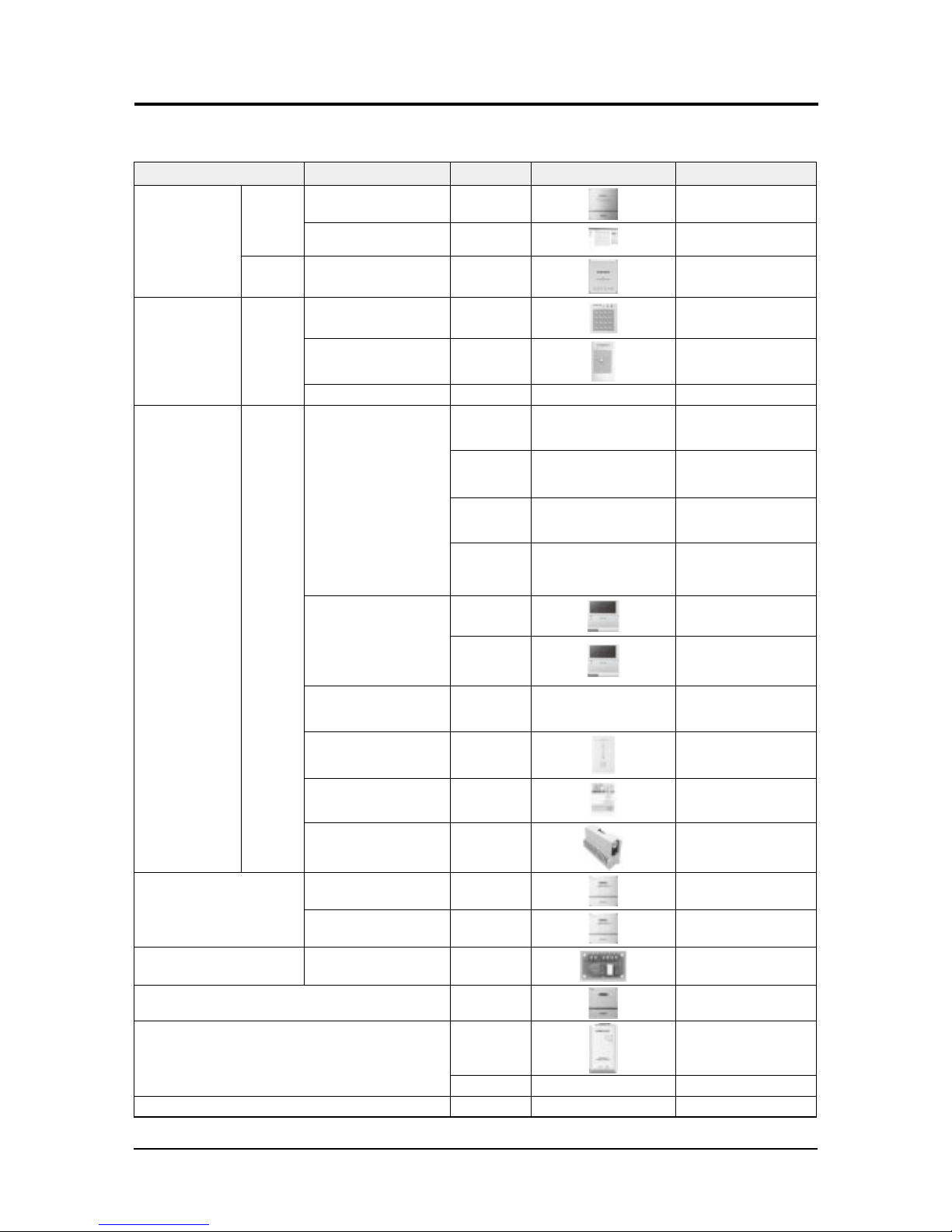
Classification Product Model Image Application model
Integrated manage
-
ment system
Controller
DMS 2 MIM-D00AN
DVM Series, FJM, CAC, ERV
Hydro unit, Hydro unit HT
S-NET 3 MST-P3P
DVM Series, FJM, CAC, ERV
Hydro unit, Hydro unit HT
Interface
Module
SIM MIM- MIM-B12N
DVM Series, FJM
Centralized control
system
Controller
Centralized controller MCM-A202DN
DVM Series, FJM, CAC, ERV
Hydro unit, Hydro unit HT
Operation mode
selection switch
MCM-C200
DVM Series
(Except HR models)
New touch CONTROLLER MCM-A300N
Individual
control system
ControllerController
Controller
Wireless remote controller
MR-DH00
Cassette, Duct
(Receiver needed)
MR-EH00
Cassette, Duct
(Receiver needed)
MR-KH00
360 cassette
AR-EH03E
All model
Wired remote controller
(Multi function)
MWR-WE10N
Cassette, Wall-mounted,
Ceiling, Duct, Console, ERV
MWR-WE13N
All model
Wired remote controller
(Multi function)
MWR-WW00N Hydro unit / Hydro unit HT
Wireless signal receiver MRK-A10
Duct (For wireless remote
controller)
Remote sensor MRW-TA
Cassette, Wall-mounted,
Ceiling, Duct, Console
ERV CO2 Sensor MOS-C1
ERV, ERV PLUS
Building management system
Lonworks interface module MIM-B18N
DVM Series, FJM, CAC, ERV
DMS-Bnet (BACnet) MIM-B17N
DVM Series, FJM
Hydro unit, Hydro unit HT
Guest room management system
External contact
interface module
MIM-B14
Mini DVM(R-410A), DVM
PLUS III, FJM
Power distribution MIM-B16N
DVM Series, FJM
Converter
MIM-C02N
DVM Series, FJM, CAC
MIM-N00
Multi Tenant Function Controller MCM-C210
※ DVM Series : DVM mini, DVM PLUS III, DVM PLUS III HR, DVM PLUS IV, DVM PLUS IV HR
Product Specifications
14
Samsung Electronics
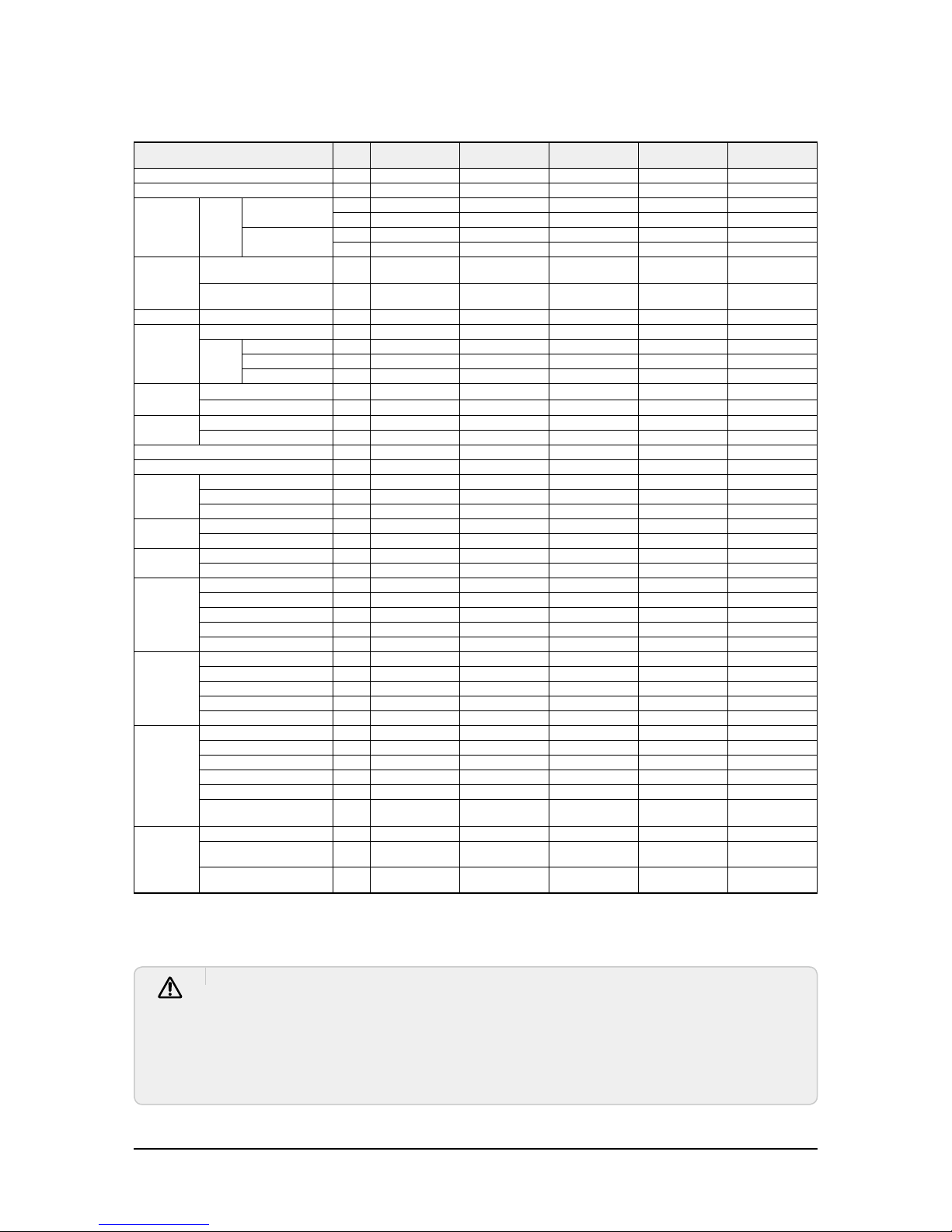
Classification Feature
Model Description Relevant unit Remark
Y-JOINT
MXJ-YA1509M
15.0 kW and below
DVMS HP / HR Requisite
MXJ-YA2512M
Over 15.0 ~ 40.6 kW and below
MXJ-YA2812M
Over 40.6 ~ 46.4 kW and below
MXJ-YA2815M
Over 46.4 ~ 69.6 kW and below
MXJ-YA3419M
Over 69.6 ~ 98.6 kW and below
MXJ-YA4119M
Over 98.6 ~ 139.2 kW and below
MXJ-YA4422M
Over 139.2 kW
Y-joint(High
Pressure Gas)
for DVM S HR
MXJ-YA1500M
23.2 kW and below
DVMS HR Requisite
MXJ-YA2500M
Over 23.2 ~ 69.6 kW and below
MXJ-YA3100M
Over 69.6 ~ 139.2 kW and below
MXJ-YA3800M
Over 139.2 kW
Outdoor joint
(Outdoor
Connection)
MXJ-TA3819M
Below 48 HP
DV
MS HP / HR Requisite
MXJ-TA4422M
Over 50 HP
Outdoor joint
(High Pressure
Gas) for DVM S HR
MXJ-TA3100M
Below 48 HP
DVMS HR Requisite
MXJ-TA3800M
Over 50 HP
Header joint
MXJ-HA2512M
Below 46.4 kW
DVMS HP / HR Requisite
MXJ-HA3115M
Below 69.6 kW
MXJ-HA3819M
Over 69.7 kW
EEV kits
MXD-E13K116A
Below 3.6 kW (1 Room) +
5.6 kW ~9.0 kW (1Room)
Wall-mounted &
Ceiling indoor unit
(For 2 indoor units)
Option
MXD-E13K200A
Below 3.6 kW (2 Rooms)
MXD-E16K200A
5.6 kW~9.0 kW (2Rooms)
MXD-E22K200A
Over 9.0 kW (2Rooms)
MXD-E13K216A
Below 3.6 kW (2 Rooms) +
5.6 kW ~9.0 kW (1Room)
Wall-mounted &
Ceiling indoor unit
(For 3 indoor units)
MXD-E13K300A
Below 3.6 kW (3 Rooms)
MXD-E16K213A
Below 3.6 kW (1 Room) +
5.6 kW ~9.0 kW (2Rooms)
MXD-E16K300A
5.6 kW ~ 9.0 kW (3Rooms)
MEV-E13SA
Below 3.6 kW (1 Room)
Wall-mounted &
Ceiling indoor unit
(for single unit)
MEV-E16SA
5.6 kW ~ 9.0 kW (1Room)
Drain Pump
MDP-N047SNC1D
HSP Duct 22.0/28.0kW -
Option
MDP-M075SGU1D
MSP Duct (9.0/11.2) kW
-
MDP-M075SGU2D
MSP
HSP Duct (11.2/12.8/14.0) kW
Duct (12.8/14.0) kW
MDP-M075SGU3D
MSP Duct (5.6/7.1) kW
MDP-E075SEE3D
MDP-G075SQ
(Internal installation)
Global Duct
GD-S Big Duct
SlimDuct (1.7~14.0) kW -
-
MDP-G075SP
(External installation)
-

Product Specifications
Samsung Electronics
15
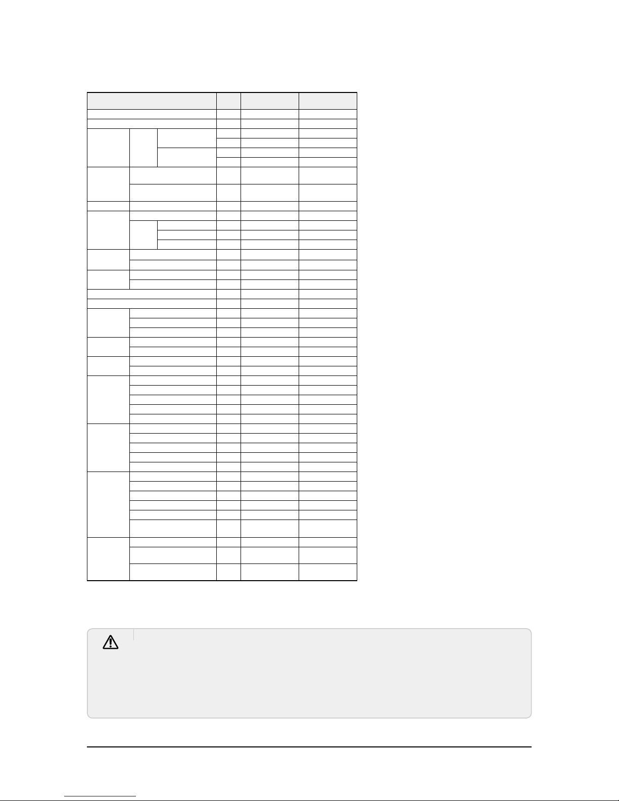
Classification Feature
Model Description Relevant unit Remark
PDM KIT
MXD-A38K2A
8~12HP
DVMS Option
MXD-A58K2A
14~22HP
Humidifier
MVO-VA050100
500CMH
- Option
MVO-VA100100
1000CMH
S-Plasma Ion KIT
MSD-CAN1
4way Cassette
- Option
MSD-EAN1
ERV-Plus
Motion detect
sensor
MCR-SMA
4way Cassette - Option
Front panel
PC1NUSMAN
Slim
PC1BWSMAN
PC1MWFMAN
PC1NWFMAN
PC1BWFMAN
Slim 1way cassette
Wind-free 1way cassette
PC1NWSMAN
Slim 1way cassette
PC1MWSKAN
Slim 1way cassette
1way cassette
- Requisite
PC1NUPMAN
Slim 1way cassette
PC2NUSMEN
2 way cassette
PC4SUSMAN
Mini 4way cassette
PC4SYSMEN
Mini 4way cassette
PC4NUSKAN
4 way cassette
PC4NUSKEN
4 way cassette
PC4NBSKAN
PC4NUDMAN
PC4NUNMAN
4 way
360 cassette
360 cassette
cassette
MCU
MCU-S4NEE1N
Below 4 indoor units
DVMS HR
Requisite
(HR Only)
MCU-S6NEE1N
Below 2 large capacity ducts
MCU-S4NEE2N
Below 6 indoor units
AHU KIT
MXD-K025AN
7.0kW~8.75kW
- Option
MXD-K050AN
14.0kW~17.5kW
MXD-K075AN
21.0kW~26.25kW
MXD-K100AN
28.0kW~35.0kW

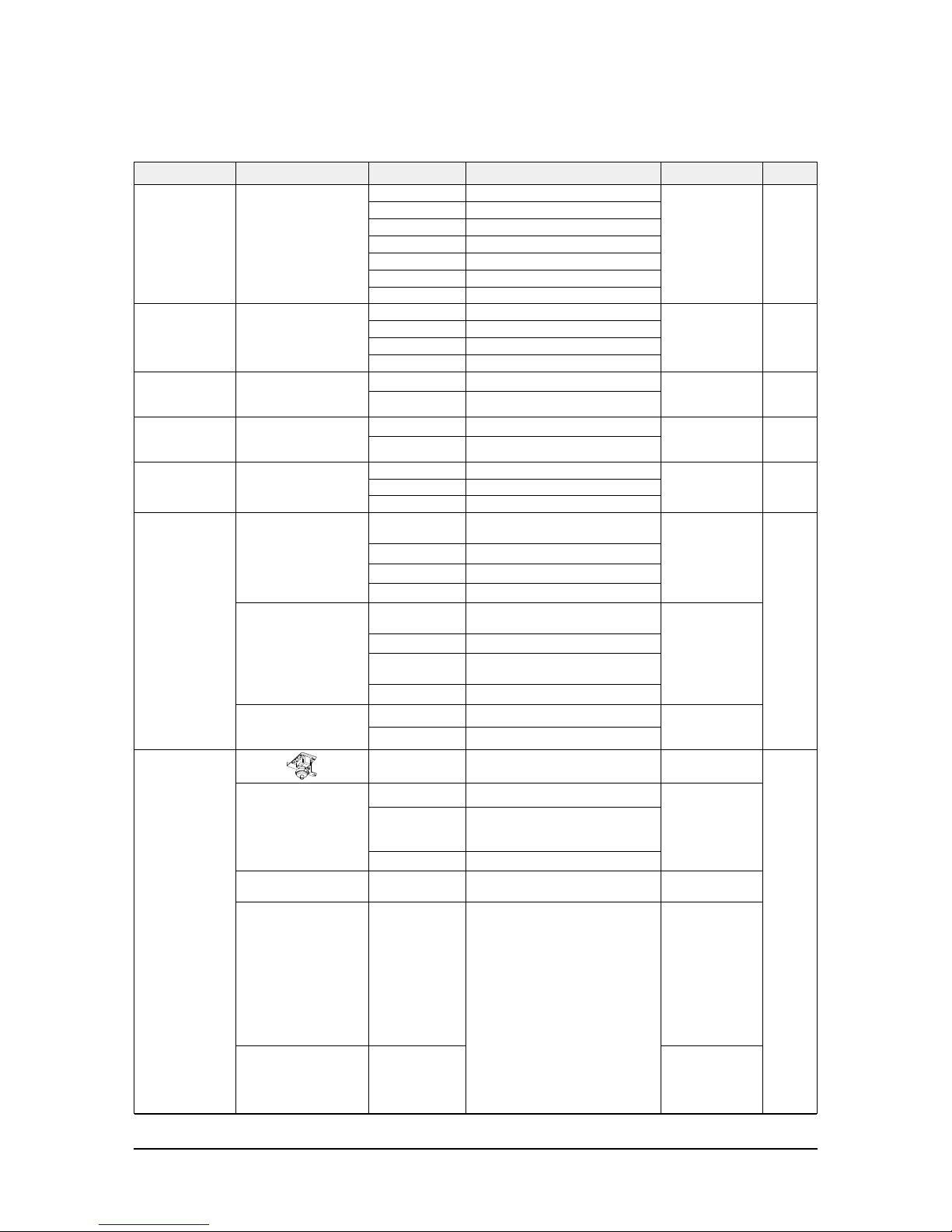
16
Samsung Electronics
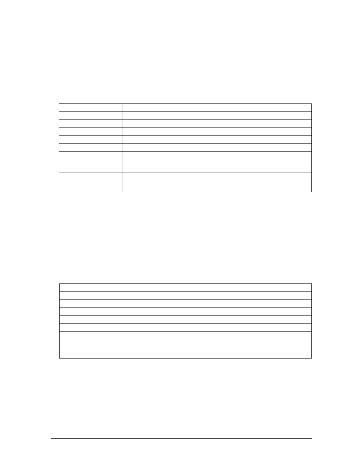
■ Necessary Tools
3. Disassembly and Reassembly
Item Remark
+Screw Driver
Monkey Spanner
–Screw Driver
Nipper
Electric Motion Driver
L-Wrench
Disassembly and Reassembly
Samsung Electronics
17
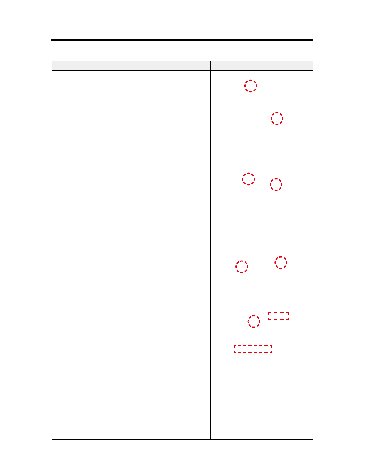
No Parts
Procedure Remark
1 Panel
1)
Pull two levers below Samsung logo to open
the grille.
2) Detach the safety clip and white link from the
panel.
3) Remove the 2 fixed screws to remove the
Control-Box Cover.(Use +Screw Driver)
4)
Remove the 4 connector wires from the PBA.
(Remocon-Receiver, Blade motor and Humidity
sensor.)
5)
Detach the 4 corners of the panel using both
hands.
3-1 Indoor Unit
■ AM045/056/071/090/112/128/140NN4DEH/**
AM009/012/018/024/036/048NN4DCH/**

Disassembly and Reassembly
18
Samsung Electronics
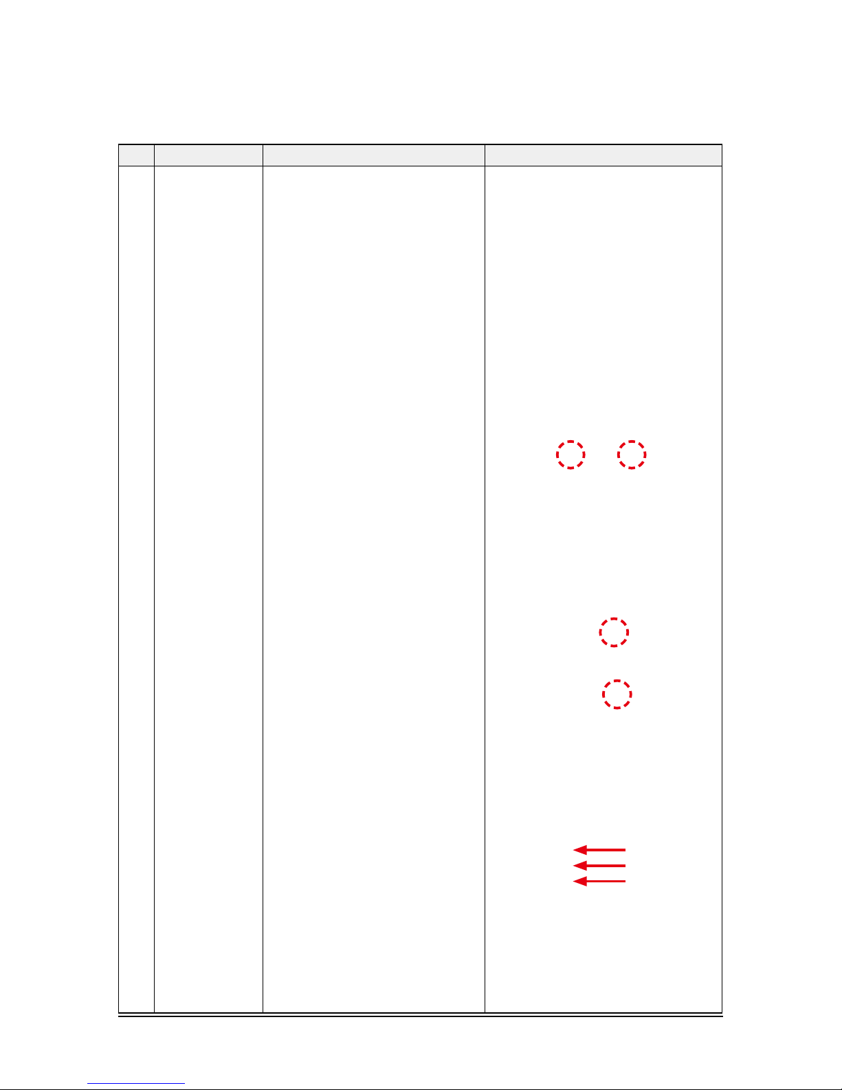
No Parts
Procedure Remark
6) RDisassemble the bolts that are assembled
with the indoor unit at the 4 panel corners.
7) PPress the Steel Hangers at both sides of the
panel inwards, and rotate them 90 degrees
to remove it from the indoor unit’s Hock.
Remove the panel from the indoor unit.
2 Control-Box 1) Disconnect the Connector Wire that is con-
nected to the indoor unit’s PBA from the PBA.
2) Unscrew the 2 fixed screws on both sides of
the Control Box, and disassemble the Control
Box from the indoor unit. (Use +Screw Driver)

Disassembly and Reassembly
Samsung Electronics
19
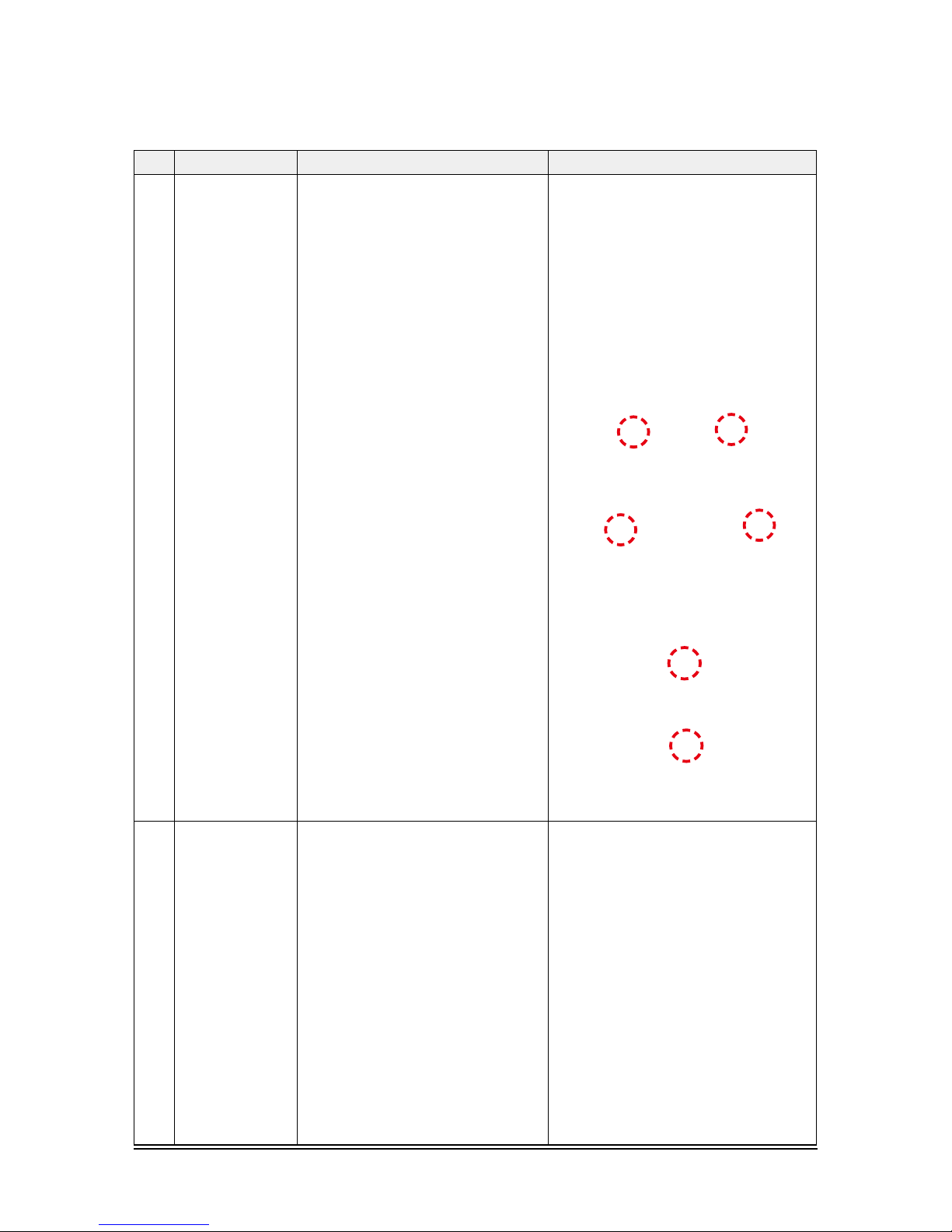
No Parts
Procedure Remark
3 Bell-Mouth 1) Unscrew the screw fixed on the Bell-Mouth.
(Use +Screw Driver)
2) Push the Bell-Mouth in the direction opposite
to where it’s installed on the Control-Box to
remove it.
4 Drain Pan 1) Unscrew the screws on the 4 corners of the
indoor unit. (Use +Screw Driver)
2) Remove the Drain Pan from the indoor unit.
Disassembly and Reassembly
20
Samsung Electronics
No Parts
Procedure Remark
1 Panel
1)
Pull both hooks and take the grille downward.
Two safety clips are mounted to the front grille
to prevent it from dropping.
2) Detach the safity clip and take up the grille.
3) Remove the 2 fixed screws to remove the
Control-Box Cover. (Use +Screw Driver)
4)
Remove the Remocon-Receiver and Blade
Connector Wire from the PBA. (3EA)
■ AM015/022/028/036/045/056/060NNNDEH/**
AM005/007/009/012/018/020NNNDCH/**
Disassembly and Reassembly
Samsung Electronics
21
No Parts
Procedure Remark
1 Panel
5)
Push the 4 panel corners and cover downwards
to remove it.
6) Disassemble the bolts that are assembled with
the indoor unit at the 4 panel corners.
7) Press the Hangers at both sides of the panel
inwards, to remove it from the indoor unit’s
hook. Remove the panel from the indoor unit.
2
Control-Box
1) Disconnect the Connector Wire that is
connected to the indoor unit’s PBA.
Disassembly and Reassembly
22
Samsung Electronics
No Parts
Procedure Remark
2
Control-Box
2)
Unscrew the 2 fixed screws on both sides of
the Control Box, and disassemble the Control
Box from the indoor unit. (Use +Screw Driver)
3
Bell-Mouth
1) Unscrew the screw fixed on the Bell-Mouth.
(Use +Screw Driver)
1) Push the Bell-Mouth in the direction opposite
to where it’s installed on the Control-Box to
remove it.
4
Drain Pan
1) Unscrew the screws on the 4 corners of the
indoor unit. (Use +Screw Driver)

Disassembly and Reassembly
Samsung Electronics
23
No Parts
Procedure Remark
4
Drain Pan
1) Remove the Drain Pan from the indoor unit.
24
Samsung Electronics
4. Troubleshooting
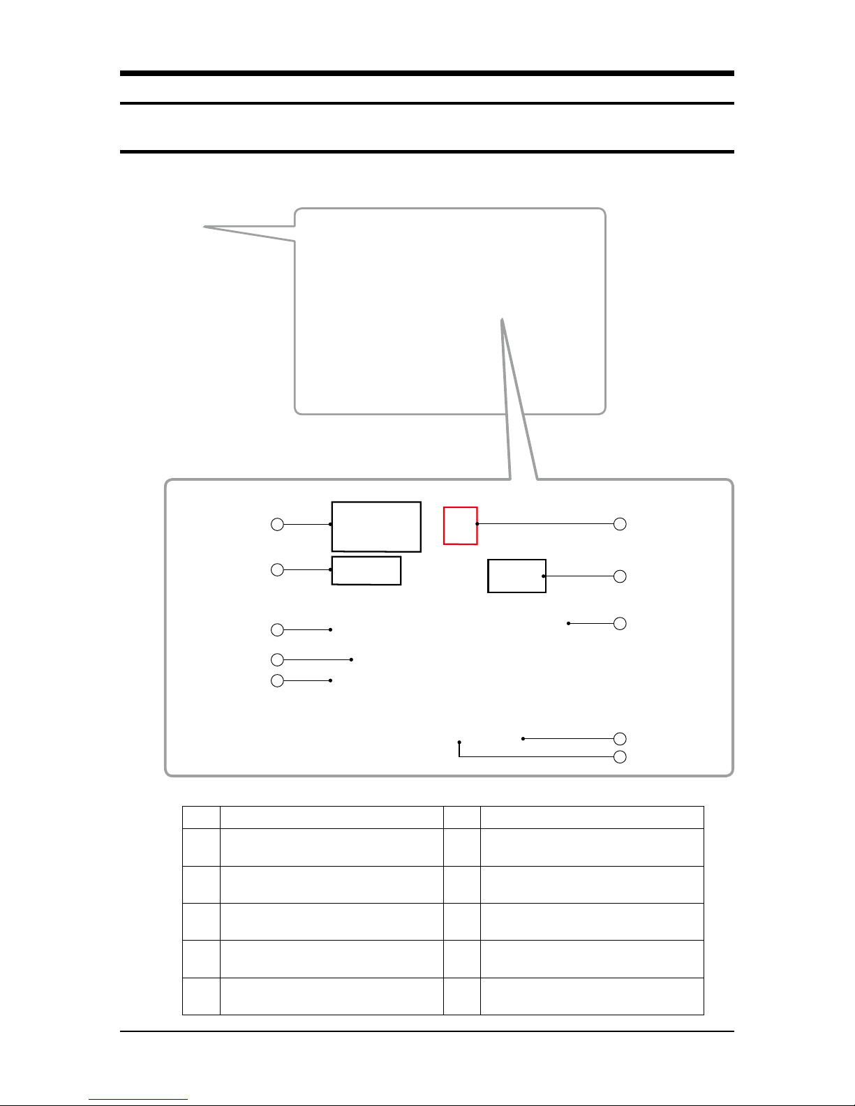
4-1 Check-up Window Description
No. Function No. Function
1
CN22 download (PC)
(SMW200-10 black)
6 Set up the number of connected outdoor units
2
MICOM. download (AS-PRO)
(SMW200-07P white)
7
For checking indoor unit communication
(YW396-02P red)
3 ERROR DISPLAY
8
Transmitter 12V
(YW396-02P blue)
4
State Check
(SMW250-04P red)
9 Outdoor Unit Tact Switch
5 EEPROM SOCKET 10 Outdoor Unit Dip Switch
3
6
8
7
4
9
1
5
2
10
Troubleshooting
Samsung Electronics
25
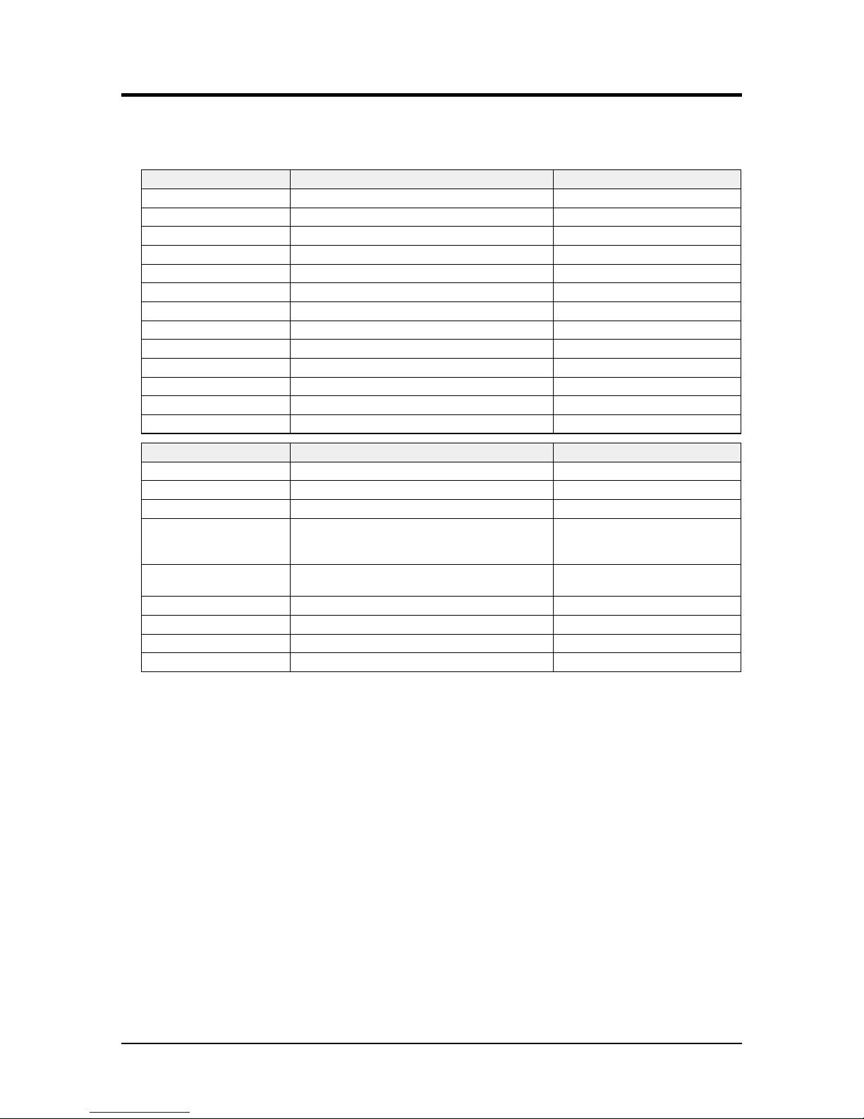
4-2 Service Operation
4-2-1 Special Operation
► Key input of the outdoor unit when the service enters the operation mode.
K1 (Number of press) Key operation Display on segment
1 time Refrigerant charging in Heating mode K, 1, BLANK, BLANK
2 times Trial operation in Heating mode K, 2, BLANK, BLANK
3 times Pump out in Heating mode (Outdoor unit address 1) K, 3, BLANK, 1
4 times Pump out in Heating mode (Outdoor unit address 2) K, 3, BLANK, 2
5 times Pump out in Heating mode (Outdoor unit address 3) K, 3, BLANK, 3
6 times Pump out in Heating mode (Outdoor unit address 4) K, 3, BLANK, 4
7 times Vacuumig (Outdoor unit address 1) K, 4, BLANK, 1
8 times Vacuumig (Outdoor unit address 2) K, 4, BLANK, 2
9 times Vacuumig (Outdoor unit address 3) K, 4, BLANK, 3
10 times Vacuumig (Outdoor unit address 4) K, 4, BLANK, 4
11 times Vacuuming (All outdoor units) K, 4, BLANK, A
12 times End Key operation
-
Press and hold 1 time Auto trial operation
K, K, BLANK, BLANK
K2 (Number of press) Key operation Display on segment
1 time Refrigerant charging in Cooling mode K, 5, BLANK, BLANK
2 times Trial operation in Cooling mode K, 6, BLANK, BLANK
3 times Pump down all units in Cooling mode K, 7, BLANK, BLANK
4 times
H/R: Checking the pipe connection
H/P: Automatic setting of operation mode (Cooling/Heating)
for trail operation
K, 8, BLANK, BLANK
5 times Checking the amount of refrigerant
K 9 X X (Display of last two digits may differ
depending on the progress)
6 times Discharge mode of DC link voltage K, A, BLANK, BLANK
7 times Forced defrost operation K, B, BLANK, BLANK
8 times Forced oil collection K, C, BLANK, BLANK
9 times End Key operation -
※ Inv1 & Inv2 voltage during discharge mode are displayed alternately.
※ Outdoor Power Off even when the Inverter PCB, Fan PCB is a high DC voltage charging contacts at danger.
※ When you run the repair and replacement of the PCB should work after the power is turned off, the DC voltage discharge.
(Natural discharge until Please wait for at least 15 minutes.)
※ If an error occurs, the discharge mode may not work properly.
In particular, E464 & E364 is power devices can be damaged.
Therefore, the discharge mode, do not use.
Troubleshooting
26
Samsung Electronics
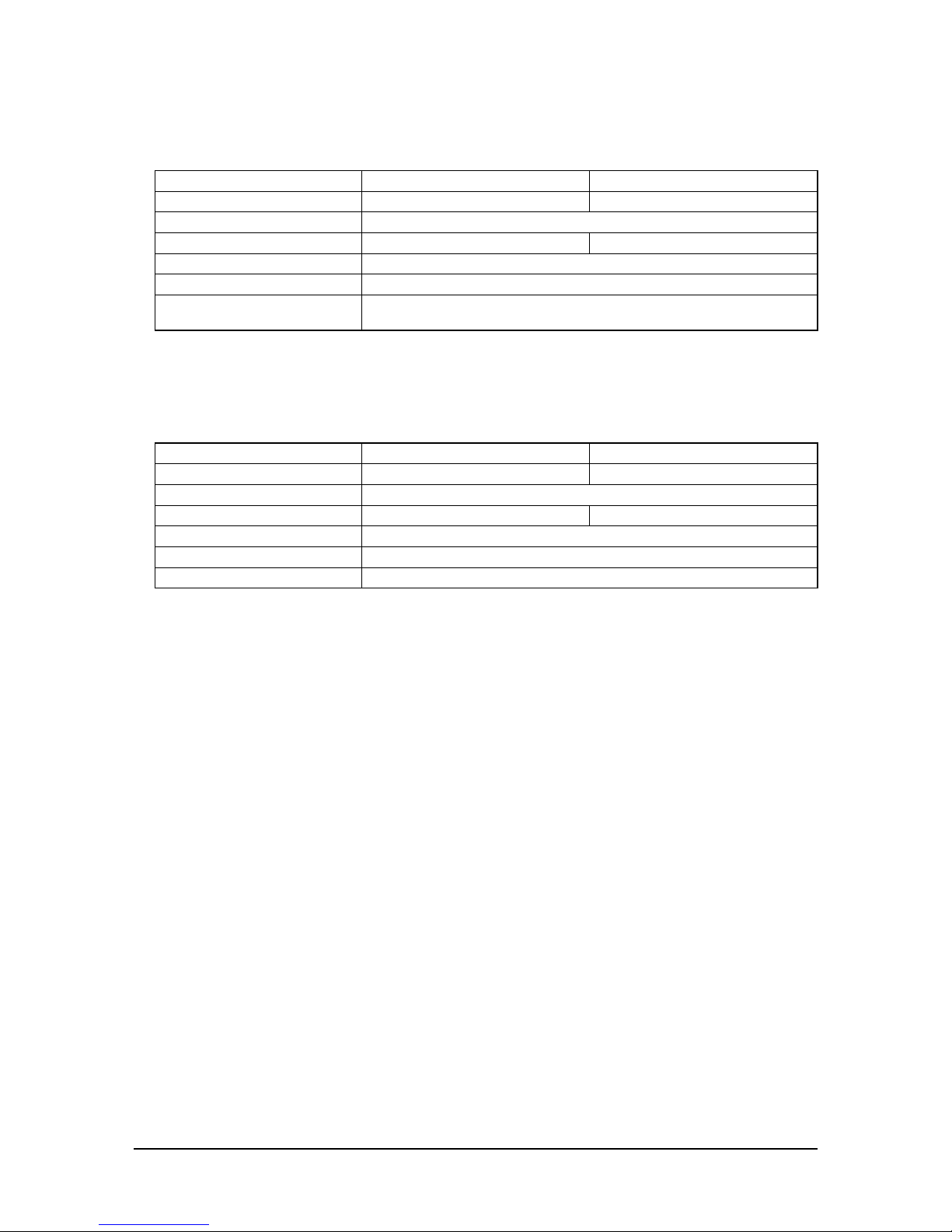
■
Commissioning
► After initial installation, stable operation for a certain period of time limited to operation conditions.
Cooling Heating
Method of Entry K2 Tac t Switch twice K2 Tact Switch twice
Compressor Normal operation, but the maximum frequency limit (differ by model)
Indoor Unit Whole operation (The set temperature=3°C) Whole operation ( The set temperature=40°C)
Outdoor fan and valves Normally control conduct
Operation time Min : 60 minutes, Max : 10 hours
Etc. Exceed the maximum operating time at stops and waits.
Protection and control, self-diagnosis is performed.
■
Refrigerant lling operation
► Operation to filling the refrigerant compressor was fixed at a certain frequency.
Cooling Heating
Method of Entry K2 Tact Switch one time K1 Tac t Switch one time
Compressor Starting frequency (Mild Start frequency) operation
Indoor Unit Whole operation (The set temperature=3°C) Whole operation ( The set temperature=40°C)
Outdoor fan and valves Normally control conduct
Operation time 60 minutes
Etc. During the filling operation does not enter the special operation, such as oil recovery, defrost.
Troubleshooting
Samsung Electronics
27
■
Heating Pump Out
► Operation for the repair of the Individual outdoor unit, the outdoor unit refrigerant emissions to the indoor part.
► Liquid pipe service valve and the gas pipe service valve operation, the operator manually need to close.
► Observe low pressure using View Mode of K4 button if compressor operate.
If low pressure goes down below about 0.2 MPa.g : Immediately lock the gas side service valve, Pump Out operation is shut down.
(Pump out operation shut down : K1 button once more press or K3 button one time press)
► If operation of low pressure goes down below 0.1 MPa.g : Will be stopped automatically for the protection of the compressor.
How to Initiate K1 Tac t Switch 3 times~6 times
Compressor 60Hz
Indoor Unit Whole Operation (The set temperature=40°C)
4Way Valve ON (Heating Mode)
Outdoor Fan Maximum air flow
Main EEV Operation side : 700 Step (Stop side : 0 step)
Maximum Operation Time 10 minutes
Protection Control Conduct the discharge temperature, high pressure control. (Low pressure protection control is not carried out)
※ Low pressure is outside normal limits : Operation is shut down after gas pipe manually closed.
Etc. Entry after safety start. (Only the corresponding Outdoor Unit operation.)
To pump out more than 2 : Except communication between Outdoor Unit of relevant set after working for one,
remainder set makes Pump Out add.
■
Cooling Pump Down
► Recover the refrigerant of Indoor Unit and Piping to outdoor side.
► Liquid pipe service valve and the gas pipe service valve operation, the operator manually need to close.
► If the installation of the long pipe : Any refrigerant into the outdoor unit can not be recovered, therefore should use a separate container.
► Observe low pressure using View Mode of K4 button if compressor operate.
If low pressure goes down below about 0.2 MPa.g : Immediately lock the gas side service valve, Pump Out operation is shut down.
(Pump out operation shut down : K1 button once more press or K3 button one time press)
► If operation of low pressure goes down below 0.1 MPa.g : Will be stopped automatically for the protection of the compressor.
How to Initiate K2 Tact Switch 3 times
Compressor Address No.1 Outdoor Unit - 60Hz (Other Outdoor Unit COMP OFF)
Indoor Unit Whole Operation (The set temperature=3°C)
4Way Valve OFF (Cooling Mode)
Outdoor Fan Maximum air flow
Main EEV Operation side : 2000 Step , Stop side : 2000 step
Maximum Operation Time 30 minutes
Etc. Does not conduct the operation of the special operation, and protection control.
Pressure and temperature is outside normal limits : Operation is shut down after gas pipe manually
closed.

Troubleshooting
28
Samsung Electronics
■
Vacuum Operation
► Operation to facilitate vacuum to open the valve after the Outdoor Unit repair.
■
Piping Inspection Operation
► Operation mode to check the status of the piping between the MCU and the indoor unit.
► Heat Pump Model : Outdoor temperature is more than 15°C / Cooling commissioning start
Outdoor temperature is less than 15°C / Heating commissioning start
■
Discharge Mode Operation
► Outdoor power is turned off, the Inverter PCB and Fan PCB charging a high DC voltage, so dangerous to touch.
- To replace the PCB, first turn off the power and the begin if DC voltage is discharged.
- If not use the discharge mode, the discharge time of about 15 minutes takes.
- If an error occurs, the discharge mode may not properly run. (Wait until natural discharge.)
- In particular, E 464, E364, power devices may be damaged, therefore do not use the discharge mode.
► Block the Inverter PCB 3-phase relay after connected the power, and through compressor, DC voltage is discharging.
- INV1 and INV2 DC voltage during discharge mode are displayed alternately.
-Discharge mode Display (Rotate the three page display, as shown below.)
'K' 'A' '' ' ‘
→
DC Link Volt1 ( For example, 120[V] 0 1 2 0 display)
→ DCLinkVolt2 ( For example, 120[V] 0 1 2 0 display) 'K' 'A' '' ' ‘ DC Link Volt1 …
► Discharge is complete, the power of the Inverter PCB and Fan PCB is being blocked, communication function is blocked,
E206 will occur.
► If want operation again after complete discharge mode : Restart after K3 key to Reset or Power Reset.
How to Initiate K1 Tact Switch 7 times~11 times
Compressor OFF
Indoor Unit/Outdoor Fan OFF
4Way Valve OFF
Valves Open all valves maximum
Etc. If not turn off the vacuum mode, the start of normal operation is prohibited.
Troubleshooting
Samsung Electronics
29
■
Forced defrost operation
► Forced defrost operation : Is operation when Frost Formation occurs in the outdoor. (When carried out the service)
■
Forced oil recovery operation
► Forced oil recovery operation : Oil recovery in the outdoor unit for the purpose of moving, installation if necessary.
Method of Entry K2 Tac t Switch 6 times
Start pattern Heating commissioning pattern
Defrost start Defrost start : It is after 10 minutes which Safety Start finishes.
Defrost off General defrost operation conditions are the same as.
Etc. Defrost shut down and stop the normal pattern of the outdoor unit stop.
Method of Entry K2 Tac t Switch 7 times
Start pattern Outdoor temperature is more than 10°C : Cooling commissioning
Outdoor temperature is less than 10°C : Heating commissioning
Oil recovery start Oil recovery star t : It is after 10 minutes which Safety Start finishes.
Etc. Oil recovery shut down and stop the normal pattern of the outdoor unit stop.
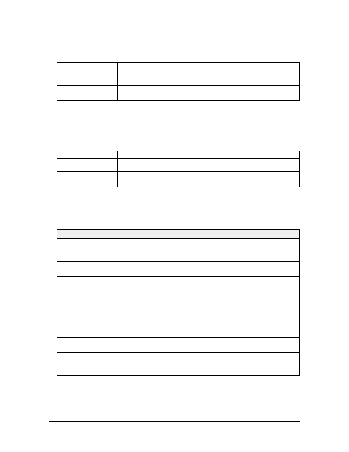
4-2-2 DVM S Models EEPROM Code Table
No. Model Name EEP Code
1 AM080FXVAGH/EU DB82-01358A
2 AM100FXVAGH/EU DB82-01359A
3 AM120FXVAGH/EU DB82-01360A
4 AM140FXVAGH/EU DB82-01361A
5 AM160FXVAGH/EU DB82-01362A
6 AM180FXVAGH/EU DB82-01363A
7 AM200FXVAGH/EU DB82-01364A
8 AM220FXVAGH/EU DB82-01365A
9 AM080FXVAGR/EU DB82-01330A
10 AM100FXVAGR/EU DB82-01331A
11 AM120FXVAGR/EU DB82-01332A
12 AM140FXVAGR/EU DB82-01333A
13 AM160FXVAGR/EU DB82-01334A
14 AM180FXVAGR/EU DB82-01335A
15 AM200FXVAGR/EU DB82-01336A
16 AM220FXVAGR/EU DB82-01337A
17 AM080FXMDGH/EU DB82-01774A
18 AM090FXMDGH/EU DB82-01776A
Troubleshooting
30
Samsung Electronics
4-3 Troubleshooting
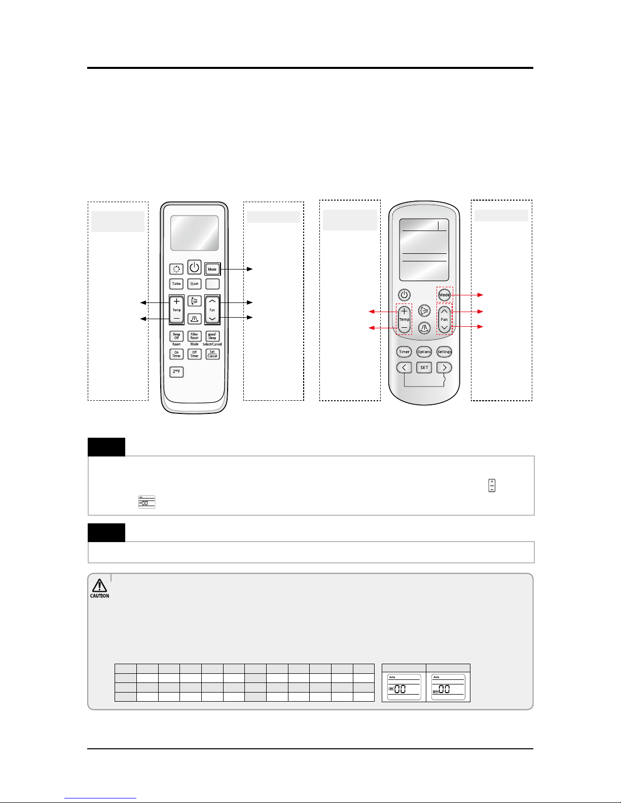
4-3-1 Setting Option Setup Method
4-3-1-1 PCB option code input method
▶
Set the indoor unit address and installation option with remote controller option.
Set the each option separately since you cannot set the ADDRESS setting and indoor unit installation setting option at the
same time.You need to set twice when setting indoor unit address and installation option.
■ The procedure of setting option
High Temp Button
High Fan Button
Mode change
Low Temp Button
Low Fan Button
Entering mode for
setting option
Option setting mode
Step 1
Entering mode to set option
1. Remove batteries from the remote controller.
2. Insert batteries and enter the option setting mode while pressing High Temp button and Low Temp button
.
3.
Check if you have entered the option setting status.
Step 2
The procedure of option setting
After entering the option setting status, select the option as listed below.
• The total number of available options are 24: SEG1 to SEG24.
• Because SEG1, SEG7, SEG13, and SEG19 are the page options used by the previous remote control models, the modes to set values
for these options are skipped automatically.
• Set a 2-digit value for each option pair in the followinig order: SEG2 and SEG3
→
SEG4 and SEG5
→
SEG6 and SEG8
→
SEG9 and
SEG10
→
SEG11 and SEG12
→
SEG14 and SEG15
→
SEG16 and SEG17
→
SEG18 and SEG20
→
SEG21 and SEG22
→
SEG23 and
SEG24.
High Temp Button
High Fan Button
Mode change
Low Temp Button
Low Fan Button
Entering mode for
setting option
Option setting mode
On(SEG1~12) O(SEG13~24)
SEG1 SEG2 SEG3 SEG4 SEG5 SEG6 SEG7 SEG8 SEG9 SEG10 SE G11 SEG12
0 X X X X X 1 X X X X X
SEG13 SEG14 SEG15 SEG16 SEG17 SEG18 SEG19 SEG20 SEG21 SEG22 SEG23 SEG24
2 X X X X X 3 X X X X X
 Loading...