


AM096FXVAFH series
Samsung AM096FXVAFH series, AM120FXVAFR series, AM120FXVAFH series, AM096FXVAFR series, AM072FXVAFR series Service Manual
...
AIR CONDITIONER CONTENTS
SYSTEM AIR CONDITIONER
1. Precautions
2. Product Specifications
3. Disassembly and Reassembly
4. Troubleshooting
5. PCB Diagram and Parts List
6. Wiring Diagram
7. Cycle Diagram
8. Key Options
9. Test Operation
10. Reference Sheet
OUTDOOR UNIT
AM072/096/120/144FXVAFH
6
AM072/096/120/144FXVAFR
6
AM072/096/120/144FXVAJH
6
AM072/096/120/144FXVAJR
6
AM072/096/120/192HXWAFR
AM072/096/120/192HXWAJR
AM168/192HXVAFH
6
AM168/192HXVAFR
6
AM168/192HXVAJH
6
AM168/192HXVAJR
6
AM072/096KXVTF
6
AM072/096KXVTJ
6
AM216KXVGJH
AM038/048/055KXWDCH

Section 0
Samsung Electronics 3
Contents
1. Precautions .......................................................................................................... 1-1
1-1 Precautions for the Service ......................................................................................................................................1-1
1-2 Precautions for the Static Electricity and PL .....................................................................................................1-1
1-3 Precautions for the Safety ........................................................................................................................................1-1
1-4 Precautions for Handling Refrigerant for Air Conditioner ..........................................................................1-2
1-5 Precautions for Welding the Air Conditioner Pipe .........................................................................................1-2
1-6 Precautions for Additional Supplement of Air Conditioner Refrigerant ...............................................1-2
1-7 Other Precautions ........................................................................................................................................................1-2
2. Product Specifications ....................................................................................... 2-1
2-1 The Feature of Product ..............................................................................................................................................2-1
2-1-1 Feature ...............................................................................................................................................................2-1
2-1-2 Changes in comparison to basic mode ................................................................................................2-3
2-1-3 Structure of product .................................................................................................................................. 2-10
2-2 Product Specifications ........................................................................................................................................... 2-15
2-2-1 Outdoor Unit ................................................................................................................................................2-15
2-3 Accessory and Option Specifications ............................................................................................................... 2-24
2-3-1 Accessories ....................................................................................................................................................2-24
3. Disassembly and Reassembly ........................................................................... 3-1
3-1 Necessary Tools .............................................................................................................................................................3-1
3-2 Disassembly and Reassembly .................................................................................................................................3-2
3-2-1 AM072FXVA66 ..............................................................................................................................................3-2
3-2-2 AM096FXVAJ6/AM120FXVAJ6/AM168HXVA66/AM192HXVA66/096KXVA66
...... 3-12
3-2-3 AM096FXVAF6/AM120FXVAF6/AM144FXVA66/072KXVA 66 ........................................... 3-22
3-2-4 AM216KXVGJ✳ ............................................................................................................................................ 3-33
3-2-5 AM072/096/120HXWA66 ...................................................................................................................... 3-47
3-2-6 AM192HXWA66.........................................................................................................................................3-55
3-3 Caution at compressor exchange ...................................................................................................................... 3-62
3-4 MCU ................................................................................................................................................................................ 3-68
3-5 EEV KIT ........................................................................................................................................................................... 3-69
4. Troubleshooting .................................................................................................. 4-1
4-1 Check-up Window Description ..............................................................................................................................4-1
4-2 PCB Description ............................................................................................................................................................4-2
4-3 Service Operation ........................................................................................................................................................4-3
4-3-1 Special Operation ..........................................................................................................................................4-2
4-3-2 DVM S Models EEPROM Code Table ...................................................................................................4-13
4-3-3 Number Display Method ........................................................................................................................ 4-13
4-4 Appropriate Measures for Different Symptom ............................................................................................. 4-18
4-4-1 Outdoor Unit Operation Flow ............................................................................................................... 4-18
4-4-2 Main PCB has no power phenomenon ............................................................................................. 4-23
4-4-3 Communication Error between Indoor and Outdoor Units during Tracking.................... 4-26
4-4-4 Communication Error between Indoor and Outdoor Units after Tracking ........................ 4-30
4-4-5
Communication error between main and sub Unit of outdoor unit or between outdoor units
.. 4-32
4-4-6 Internal Communication error of the Outdoor Unit C-Box ....................................................... 4-34
4-4-7 Internal PCB Communication error of the Outdoor Unit C-Box..............................................4-36
4-4-8
MCU branch part setup error – inconsecutive connection with the use of 2 branch parts
..... 4-39
4-4-9 MCU branch part setup error-Repeated setup for the same address over 3 times ........ 4-40
4-4-10 MCU branch part setup error-non-installed address setup ................................................... 4-41
4-4-11 Setup Error for MCU Branch part – Setup Error for MCU Quantity Used ..........................4-42
4-4-12 MCUMCU branch part setup error – Overlapping Indoor unit Address setup .............. 4-43
4-4-13
MCU branch part setup error – Set as being used without connection to an Indoor unit
.. 4-44

Section 0
4 Samsung Electronics
Contents
4-4-14
MCU branch part setup error – Connect an Indoor unit to a branch part not being used
...... 4-45
4-4-15 MCU branch part setup error – Connect more Indoor units than what is actually set up in MCU .. . 4-46
4-4-16 MCU/MCU subcooler entrance/exit sensor error (Open/Short) ........................................... 4-47
4-4-17 Outdoor Temperature Sensor Error .................................................................................................. 4-48
4-4-18 Cond Out Temperature Sensor Error (Open/Short) ...................................................................4-49
4-4-19 Outdoor Cond Out sensor breakaway error ................................................................................. 4-51
4-4-20 Compressor Discharge or Top 1/2 Temperature sensor error ...............................................4-53
4-4-21 Compressor Discharge or Top temperature sensor breakaway error ................................ 4-55
4-4-22 E269 : Suction Temperature sensor breakaway error ............................................................... 4-57
4-4-23 High Pressure sensor error (Open/Short) .......................................................................................4-59
4-4-24 Low Pressure sensor error (Open/Short) ........................................................................................ 4-61
4-4-25 Suction Temperature sensor error (Open/Short) ........................................................................ 4-63
4-4-26 Liquid Pipe Temperature sensor error (Open/Short) ................................................................. 4-65
4-4-27 EVI In Temperature sensor error (Open/Short) ............................................................................ 4-67
4-3-28 EVI Out Temperature sensor error (Open/Short) ........................................................................ 4-68
4-4-29 Suction-2 Temperature Sensor Error (OPEN/SHORT) ................................................................ 4-69
4-4-30 Measures of other outdoor unit error ............................................................................................. 4-70
4-4-31 E407 : Comp. Down due to High Pressure Protection Control .............................................4-72
4-4-32 E410 : Comp. Down due to Low Pressure Protection Control ...............................................4-75
4-4-33 E416 :
Suspension of starting due to Compressor discharge temperature sensor
/ Top temperature sensor
........................................................................................................ 4-77
4-3-34 3-phase Input Wiring error ...................................................................................................................4-79
4-3-35 E428 : Suspension of starting by abnormal compression ratio ............................................ 4-80
4-3-36 EVI EEV Open error ..................................................................................................................................4-81
4-3-37 Refrigerant leakage error ...................................................................................................................... 4-83
4-3-38 Prevention of heating / cooling operation due to outdoor temperature ........................ 4-85
4-3-39 Prevention of heating refrigerant charge due to outdoor temperature ..........................4-86
4-3-40 CH wire breaking error........................................................................................................................... 4-87
4-3-41 Fan starting error ......................................................................................................................................4-90
4-3-42 Fan lock error ............................................................................................................................................. 4-91
4-3-43 Momentary Blackout error .........................................................................................................................4-92
4-3-44 Outdoor Fan Motor overheating ....................................................................................................... 4-93
4-3-45 Fan IPM Overheat error .......................................................................................................................... 4-94
4-3-46 Compressor starting error ....................................................................................................................4-95
4-3-47 COMP Overcurrent error ....................................................................................................................... 4-98
4-3-48 Overvoltage / Low voltage error .....................................................................................................4-103
4-3-49 DC Link voltage sensor error .............................................................................................................4-105
4-3-50 Fan Motor Overcurrent error .............................................................................................................4-107
4-3-51 Input / Output Current sensor error ...............................................................................................4-109
4-3-52 Outdoor Fan PCB Overvoltage / Low voltage error .................................................................4-111
4-3-53 Hall IC(Fan) error .....................................................................................................................................4-112
4-3-54 Inverter Overheat error ........................................................................................................................4-113
4-3-55 Option setting error of outdoor unit .............................................................................................4-114
4-3-56 Model mismatching of Indoor unit. ...............................................................................................4-116
4-3-57 Error due to using single type outdoor unit in a module installation .............................4-117
5. PCB Diagram and Parts List ............................................................................... 5-1
5-1 ASS'Y PCB MAIN ...........................................................................................................................................................5-1
5-2 ASS'Y PCB MAIN-HUB ................................................................................................................................................5-6
5-3 ASS’Y PCB INVERTER ............................................................................................................................................... 5-10
5-4 OUT DOOR UNIT PCB ............................................................................................................................................. 5-14
5-5 ASS’Y PCB FAN ........................................................................................................................................................... 5-16
5-6 ASS’Y PCB EMI .......................................................................................................................................................... 5-20
5-7 OUT DOOR UNIT PCB ............................................................................................................................................ 5-21
5-8 SUB-COMM ................................................................................................................................................................ 5-22
5-9 ASSY PCB WATER-HUB ............................................................................................................................................ 5-23

Section 0
Samsung Electronics 5
Contents
6. Wiring Diagram ................................................................................................... 6-1
6-1 AM072/096/120/144FXVA66 ................................................................................................................................6-1
6-2 AM072/096/120/192HXWA66 ..............................................................................................................................6-3
6-3 AM168/192HXVAJ6A .................................................................................................................................................6-5
6-4 AM168/192HXVAF6 ...................................................................................................................................................6-7
6-5 AM072/097KXVAJ6 ....................................................................................................................................................6-9
6-6 AM072KXVAF6 ..........................................................................................................................................................6-11
6-7 AM096KXVAF6 ..........................................................................................................................................................6-13
6-8 AM216KXVGJ6 .......................................................................................................................................................... 6-15
6-9 AM038/048/055KXWD6 ........................................................................................................................................ 6-17
7. Cycle Diagram ...................................................................................................................7-1
7-1 AM072FXVAFH6/AM072FXVAJH6......................................................................................................................7-1
7-2 AM096FXVAJH/AM120FXVAJH
6
..........................................................................................................................7-1
7-3 AM096FXVAFH
6
/AM120FXVAFH6/AM144FXVAFH6/AM144FXVAJH/AM168HXVAJH6/
AM168HXVAFH
6
/AM192HXVAJH6/AM192HXVAFH6 ..............................................................................7-2
7-4 AM072FXVAFR
6
/AM072FXVAJR6 .......................................................................................................................7-2
7-5 AM096FXVAJR
6
/AM120FXVAJR6 .......................................................................................................................7-3
7-6 AM096FXVAFR
6
/AM120FXVAFR6/AM144FXVAFR6/AM144FXVAJR6/AM168HXVAJR6/
AM168HXVAFR
6
/AM192HXVAJR6/AM192HXVAFR6 ................................................................................7-3
7-7 AM216KXVGJH ..............................................................................................................................................................7-4
7-8 AM192HXWA66 ..........................................................................................................................................................7-4
7-9 Cooling operation (H/R) ............................................................................................................................................7-5
7-10 Main cooling operation (H/R) ...............................................................................................................................7-6
7-11 Heating operation (H/R) .........................................................................................................................................7-7
7-12 Main heating operation (H/R) ..............................................................................................................................7-8
7-13 Cooling operation (H/P) ..........................................................................................................................................7-9
7-14 Heating operation (H/P) ......................................................................................................................................7-10
7-15 Cooling operation(H/R) ........................................................................................................................................7-11
7-16 Main cooling operation(H/R) ............................................................................................................................. 7-12
7-17 Heating operation(H/R) .......................................................................................................................................7-13
7-18 Main heating operation(H/R) ............................................................................................................................7-14
7-19 AM038KXWD66 .................................................................................................................................................... 7-15
7-20 AM048/055KXWD66 ........................................................................................................................................... 7-15
7-21 Cycle Component Function Explanation ....................................................................................................7-16
8. Key Options .........................................................................................................8-1
8-1 Outdoor unit option switch settings ...................................................................................................................8-1
8-2 How to set the key function of the outdoor unit ...........................................................................................8-4
8-3 How to check the view mode using a tact switch ...................................................................................... 8-13
9. Test Operation .....................................................................................................9-1
9-1 Auto Trial Operation ....................................................................................................................................................9-1
9-1-1 Auto Trial Operation Synopsis ..................................................................................................................9-1
9-1-2 Auto Trial Operation functions .................................................................................................................9-3
9-1-3 How to troubleshoot of the "Undetermined"....................................................................................9-4
9-1-4 Auto Trial Operation Error Code ........................................................................................................... 9-13
9-2 Amount of refrigerant automatically checking ............................................................................................ 9-14
10. Reference Sheet .............................................................................................. 10-1
10-1 Nomenclature ..........................................................................................................................................................10-1

Samsung Electronics 1-1
1. Precautions
1-1 Precautions for the Service
OUse the correct parts when changing the electric parts.
– Please check the labels and notices for the model name, proper voltage, and proper current for the electric parts.
OFully repair the connection for the types of harness when repairing the product after breakdown.
– A faulty connection can cause irregular noise and problems.
OWhen disassembling or assembling, make sure that the product is laid down on a work cloth.
– Doing so will prevent scratching to the exterior of the rear side of the product.
OCompletely remove dust or foreign substances on the housing, connection, and inspection parts when performing repairs.
– This can prevent fire hazards for tracking, short, etc.
OPlease tighten the service valve of the outdoor unit and the valve cap of the charging valve as securely as possible by using
a monkey spanner.
OCheck whether the parts are properly and securely assembled after performing repairs.
– These parts should be in the same condition as before the repair.
1-2 Precautions for the Static Electricity and PL
OPlease carefully handle the PCB power terminal during repair and measurement when it is turned on since it is vulnerable
to static electricity.
– Please wear insulation gloves before performing PCB repair and measurement.
OCheck if the place of installation is at least 2m away from electronic appliances such as TV, video players, and stereos.
– This can cause irregular noise or degrade the picture quality.
OPlease make sure the customer does not directly repair the product.
– Arbitrary dismantling may result in electric shock or fire.
1-3 Precautions for the Safety
ODo not pull or touch the power plug or the subsidiary power switch with wet hands.
– This may result in electric shock or fire.
OIf the power line or the power plug is damaged, then it must be changed since this is a hazard.
ODo not bend the wire too much or position it so that it can be damaged by a heavy object on top.
– This may result in electric shock or fire.
OThe use of multiple electric outlets should be prohibited.
– This may result in electric shock or fire.
OGround the connection if it is necessary.
– The connection must be grounded if there is any risk of electrical short due to water or moisture.
OUnplug the power or turn off the subsidiary power switch when changing or repairing electrical parts.
– Doing so will prevent electric shock.
OExplain to workers that the battery for the remote control needs to be separated for storage purposes when the product
will not be used for a long time.
– This can cause a problem for the remote control since battery fluid may trickle out.

1-2 Samsung Electronics
1-4 Precautions for Handling Refrigerant for Air Conditioner
Environmental Cautions: Air pollution due to gas release
OSafety Cautions
If liquid gas is released, then body parts that come into contact with it may experience frostbite/blister/numbness.
If a large amount of gas is released, then suffocation may occur due to lack of oxygen. If the released gas is heated, then noxious
gas may be produced by combustion.
OContainer Handling Cautions
Do not subject container to physical shock or overheating. (Flowage is possible while moving within the regulated pressure.)
1-5 Precautions for Welding the Air Conditioner Pipe
ODangerous or flammable objects around the pipe must be removed before the welding.
OIf the refrigerant is kept inside the product or the pipe, then remove the refrigerant prior to welding.
If the welding is carried out while the refrigerant is kept inside, the welding cannot be properly performed. This will also produce
noxious gas that is a health hazard. This leakage will also explode with the refrigerant and oil due to an increase in the refrigerant
pressure, posing a danger to workers.
OPlease remove the oxide produced inside the pipe during the welding with nitrogen gas.
Using another gas may cause harm to the product or others.
1-6 Precautions for Additional Supplement of Air Conditioner Refrigerant
OPrecisely calculate the refrigerant by using a scale and S-net, and proceed with the test operation.
Excessive supplement can cause harm to the product since it can cause an inflow of the liquid refrigerant into the compressor.
ODo not heat the refrigerant container for a forced injection.
This may cause harm to the product or others since the refrigerant container may burst.
ODo not operate the product after removing the product safety pressure switch and sensor.
If the product is blocked inside, then this may cause harm to the product or others due to the excess pressure increase of the
refrigerant gas.
1-7 Other Precautions
OThere should be no leakage of the pipes after installation. When withdrawing the refrigerant, the compressor should be
stopped before removing the connecting pipe.
If the compressor is operating while the refrigerant pipe is not correctly connected and the service valve is opened, then
air and other substances can enter the pipe. The interior of the refrigerant cycle may then build up excessive high pressure
resulting in explosion and damage.

Samsung Electronics 2-1
2. Product Specifications
2-1 The Feature of Product
2-1-1 Feature
Q Dual SSC System Technology
When load changes, capacity amendment that is soft by continuous operation of Dual Inverter is available.
Q Dual Smart Inverter System
DSC System
Digital base Inverter base
. DVI variable + DVI constant speed
. AC Motor
. 2 generation, Vapor Injection
. Dual Smart Inverter : SSC + SSC
. BLDC Inverter Motor (14~160Hz driving)
. 3 generation, Vapor Injection
(Performance maximization of low temperature heating)
DSI System
High Pressure Refrigerant Outlet
Medium Pressure
Refrigerant Injection
Low Pressure
Refrigerant Inlet
Low Pressure
Refrigerant Inlet
3 generation,
Vapor Injection
3 generation,
Vapor Injection
Low Pressure
Refrigerant Inlet
High Pressure Refrigerant Outlet High Pressure Refrigerant Outlet
Medium Pressure
Refrigerant Inlet
Capacity
Variable
Ŷ Compressor driving : When load changes, is variable by fast inverter frequency.
Ŷ Amenities elevation : ᇹ0.5°C
Step 1
ON OFF
Step 2
Step 3 Step 4
ON OFF
ON ON ON ON

Product Specications
2-2 Samsung Electronics
Feature
(cont.)
QInverter circuit refrigerant cooling technology
- Applied high eciency refrigerant cooling circuit. Secured stable Inverter PCB cooling performance.
- Air cooling method : When natural convection / electric heat performance is low and is high load, eciency is fallen.
- Refrigerant cooling system : Forced circulation / electric heat performance is high and control of (thermal conductivity is
10 times higher than air) load is available.
Cooling of
inverter circuit
Refrigerant cooling system :
It is cooling technology of inverter circuit that use
refrigerating cycle technology.
Cooling of
inverter circuit

Product Specications
Samsung Electronics 2-3
2-1-2 Changes in comparison to basic mode
Changed
part
Changed item
and feature
Basic After changed
Control Box
structure
Monolayer structure ࣖ Double Layer Structure
- Inverter technology integration
(Inverter control circuit composition)
- C/Box volume maximum use
Built-in type Controller embodiment
- Integrated power supply
+ control unit
- Piping service easiness
Q Control Box & PCB
Changed
part
Changed item
and feature
Basic After changed
CABINET
Change the color :
TOUCH GRAY
ࣖ EARTH BROWN
Wire Harness installation part
change
LOGO change

Product Specications
2-4 Samsung Electronics
Changes in comparison to basic mode (cont.)
Changed
part
Changed item
and feature
Basic After changed
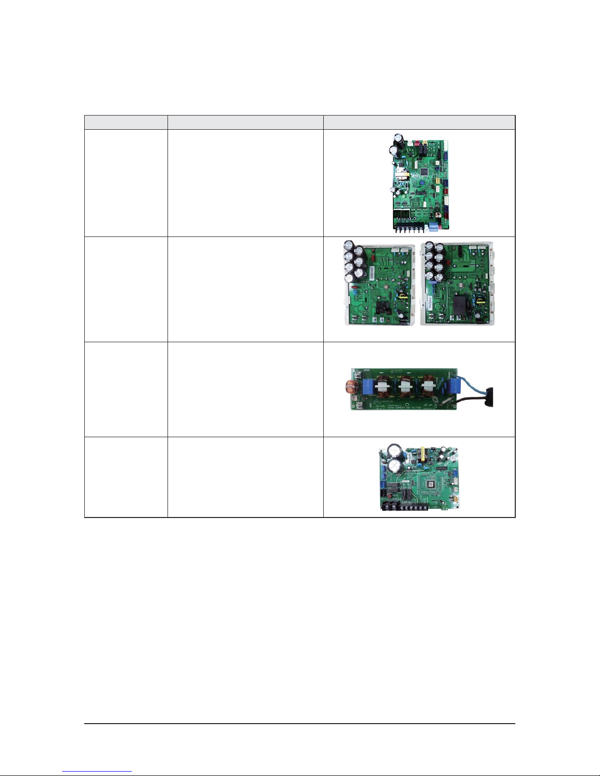
Main PCB
Change Main PCB
- Separation for load / control.
- Option resistance delete by model.
(standardization)
- When do PCB replace, need option
download.
Hub PCB
Hub PCB newly application
- Separation for load / control.
- Enhanced fixing of load / sensor
wire.
FAN PCB
Use controller of 3 phase power
- Prevented phase unbalance.
- Temperature protection of IPM.
Inverter PCB
(Compressor
Control PCB)
Applied inverter Compressor
- Refrigerant cooling method
- Magnet S/W
ױ Did Power Relay mount to PCB.
EMI PCB
3 phase power EMI PCB
- Fuse mount
-
Communication
Terminal block
Did Communication Terminal block
mount to PCB.
QAM072/096/120/144FXVA66/168HXVAJ6/192HXVAJ6/072KXVA66/096KXVAJ
6

Product Specications
Samsung Electronics 2-5
Changes in comparison to basic mode (cont.)
Changed
part
Changed item
and feature
Basic After changed
Main PCB
Change Main PCB
- Separation for load / control.
- Option resistance delete by model.
(standardization)
- When do PCB replace, need option
download.
Hub PCB
Hub PCB newly application
- Separation for load / control.
- Enhanced fixing of load / sensor wire.
FAN PCB
Use controller of 3 phase power
- Prevented phase unbalance.
- Temperature protection of IPM.
Inverter PCB
(Compressor
Control PCB)
Inverter PCB newly application
- Capacitor size increased
- EMI Coil applied
EMI PCB
EMI PCB newly application
- Coil size increased
- Fuse capacity changed
- Capacitor changed
Reactor
Reactor newly application.
- Terminal block for screw applied
-
PCB Cooling
Tube
Capacity of heat sink increased.
Tube size increased.
Communication
Terminal block
Did Communication Terminal block
mount to PCB.
Q AM168/1926XVAF6/AM096KXVAF
6
Product Specications
2-6 Samsung Electronics
Changes in comparison to basic mode (cont.)
Item Feture PBA
Main PCB
Main PCB
- Separation for load / control.
- Option resistance delete by model. (standardization)
- When replace the PCB, must download option.
- Enhanced fixing of load / control wire.
Inverter PCB
(Compressor control PCB)
Compressor control
Inverter PCB
3/4HP:PF#4 5/6HP : PF#5
EMI PCB
Single-phase power supply EMI PCB
- FUSE mount
Water Hub PCB
Water Hub PCB
-The external contact point of the water-cooled.
Q
AM038/048/055KXWD
66

Product Specications
Samsung Electronics 2-7
Changes in comparison to basic mode (cont.)
Changed
part
Changed item
and feature
Basic After changed
Main PCB
Change Main PCB
- Separation for load / control.
- Option resistance delete by model.
(standardization)
- When do PCB replace, need option
download.
←
Hub PCB
Hub PCB newly application
- Separation for load / control.
- Enhanced fixing of load / sensor
wire.
←
Inverter PCB
(Compressor
Control PCB)
Applied inverter Compressor
- Refrigerant cooling method
- Magnet S/W
ױ Did Power Relay mount to PCB.
←
EMI PCB
3 phase power EMI PCB
- Fuse mount
←
Communication
Terminal block
Did Communication Terminal block
mount to PCB.
←
Water Hub PCB
Water Hub PCB
- External contact for DVM S WATER
-
Q
AM072/096/120/192HXWA
66

Product Specications
2-8 Samsung Electronics
Changed
part
Changed item
and feature
Basic After changed
Main PCB
Change Main PCB
- Increase MICOM capability
FAN PCB
Applies 600V IPM by LC
resonance buck-converter
Inverter PCB
(Compressor
Control
PCB)
- Increases current due to
high capacity compressor
- Increases capacitor's capacity
- Applies EMI coil on board
(Deletes core in wire)
EMI PCB
- Develops 50A EMI PBA
ױIncreases coil size and
fuse capacity
- Improves EMI characteristic.
REACTOR
- Increases current due to
high capacity compressor
- Improved wire connection terminal
Refrigerant
cooling
- Increases heat cooling capacity
- Increases pipe size and heat
exchange area
Changes in comparison to basic mode (cont.)
Q
AM216KXVGJH
Product Specications
Samsung Electronics 2-9
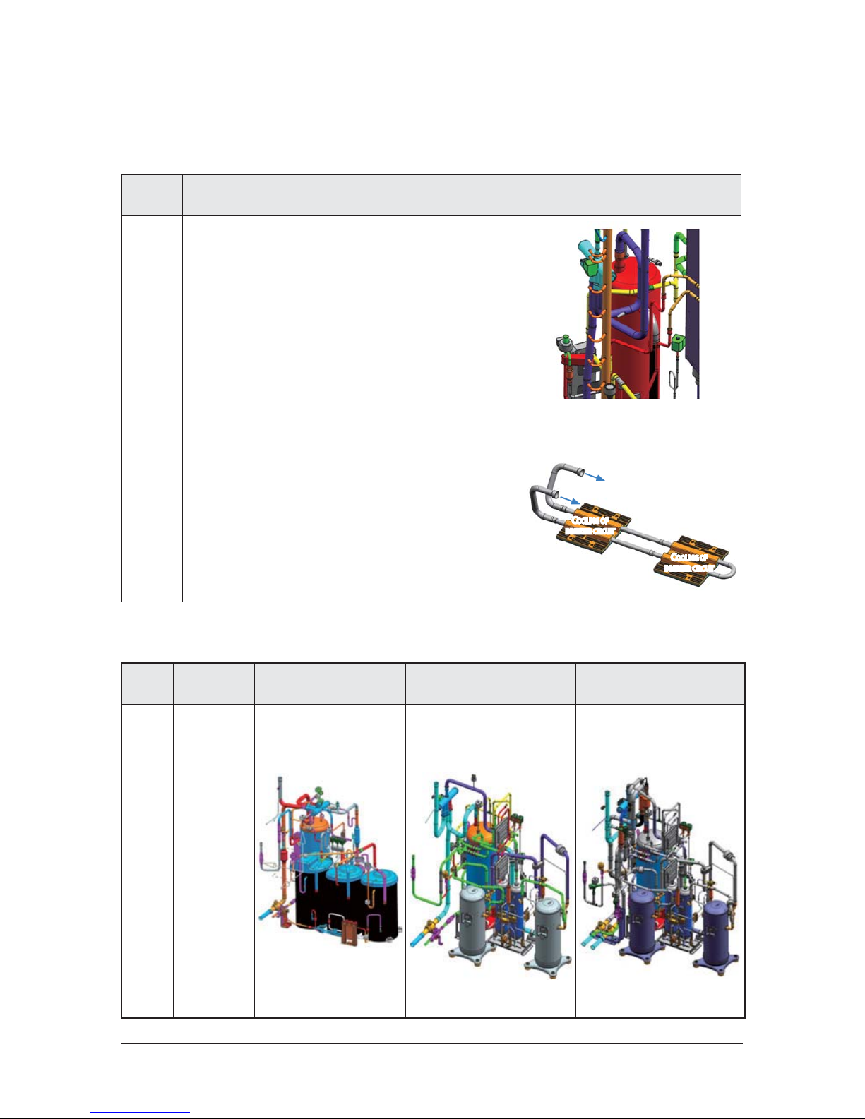
Changes in comparison to basic mode (cont.)
Changed
part
Changed item
and feature
Basic After changed
Pipe
Cooling
New Pipe Cooling for cooling
of inverter PCB.
Unapplied
C
OOLING OF
INVERTER CIRCUIT
REFRIGERANT COOLING SYSTEM :
I
T IS COOLING TECHNOLOGY OF INVERTER CIRCUIT THAT USE
REFRIGERATING CYCLE TECHNOLOGY.
C
OOLING OF
INVERTER CIRCUIT
Changed
part
Changed item
and feature
Basic After changed [HP] After changed [HR]
Tube
structure
New inverter
cycle technology
application
New piping
Q
Pipe Cooling
Q
Tube

Product Specications
2-10 Samsung Electronics
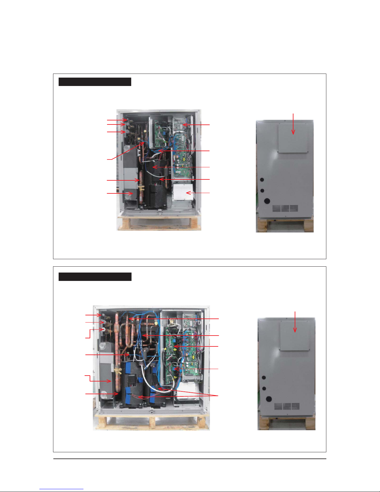
2-1-3 Structure of product
AM072FXVAF
6
AM072FXVAJ
6
AM096FXVAF
6
AM120FXVAF
6
AM144FXVAF6
AM168HXVAF
6
AM192HXVAF
6
AM072KXVAF
6
AM096KXVAF
6
AM096FXVAJ
6
AM120FXVAJ
6
AM144FXVAJ
6
AM168HXVAJ
6
AM192HXVAJ
6
AM072KXVAJ
6
AM096KXVAJ
6
TRANS BOX
TRANS BOX
Product Specications
Samsung Electronics 2-11
Heat Exchanger
Compressor
CONTROL BOX
4-WAY V/V
Subcooler
Gas Pipe
Liquid Pipe
AM216KXVGJ
6

2-12 Samsung Electronics
ACCUMULATOR
4WAY V/V
SUBCOOLER
EEV
Liquid Pipe
Gas Pipe
Plate Heat Exchanger
Compressor
CONTROL BOX
AM038/048/055KXWD
6

Product Specications
Samsung Electronics 2-13
AM072/096/120HXWAF
6
AM192HXWAF
6
CONTROL BOX
Liquid Pipe
High pressure Gas Pipe
Low pressure Gas Pipe
4 WAY V/V
Receiver
Plate Heat Exchanger
Accumulator
Sub Cooler
Compressor
Oil separator
Liquid Pipe
4 WAY V/V
Accumulator
CONTROL BOX
Oil separator
Compressor
High pressure
Gas Pipe
Low pressure
Gas Pipe
Sub Cooler
Plate Heat
Exchanger
Receiver
Product Specications
2-14 Samsung Electronics
AM072/096/120HXWAJ
6
AM192HXWAJ
6
CONTROL BOX
Liquid Pipe
High pressure Gas Pipe
Low pressure Gas Pipe
4 WAY V/V
Receiver
Plate Heat Exchanger
Accumulator
Sub Cooler
Compressor
Oil separator
TRANS BOX
TRANS BOX
Liquid Pipe
4 WAY V/V
Accumulator
CONTROL BOX
Oil separator
Compressor
High pressure
Gas Pipe
Low pressure
Gas Pipe
Sub Cooler
Plate Heat
Exchanger
Receiver
Product Specications
2-15 Samsung Electronics
Product Specications
Samsung Electronics 2-16
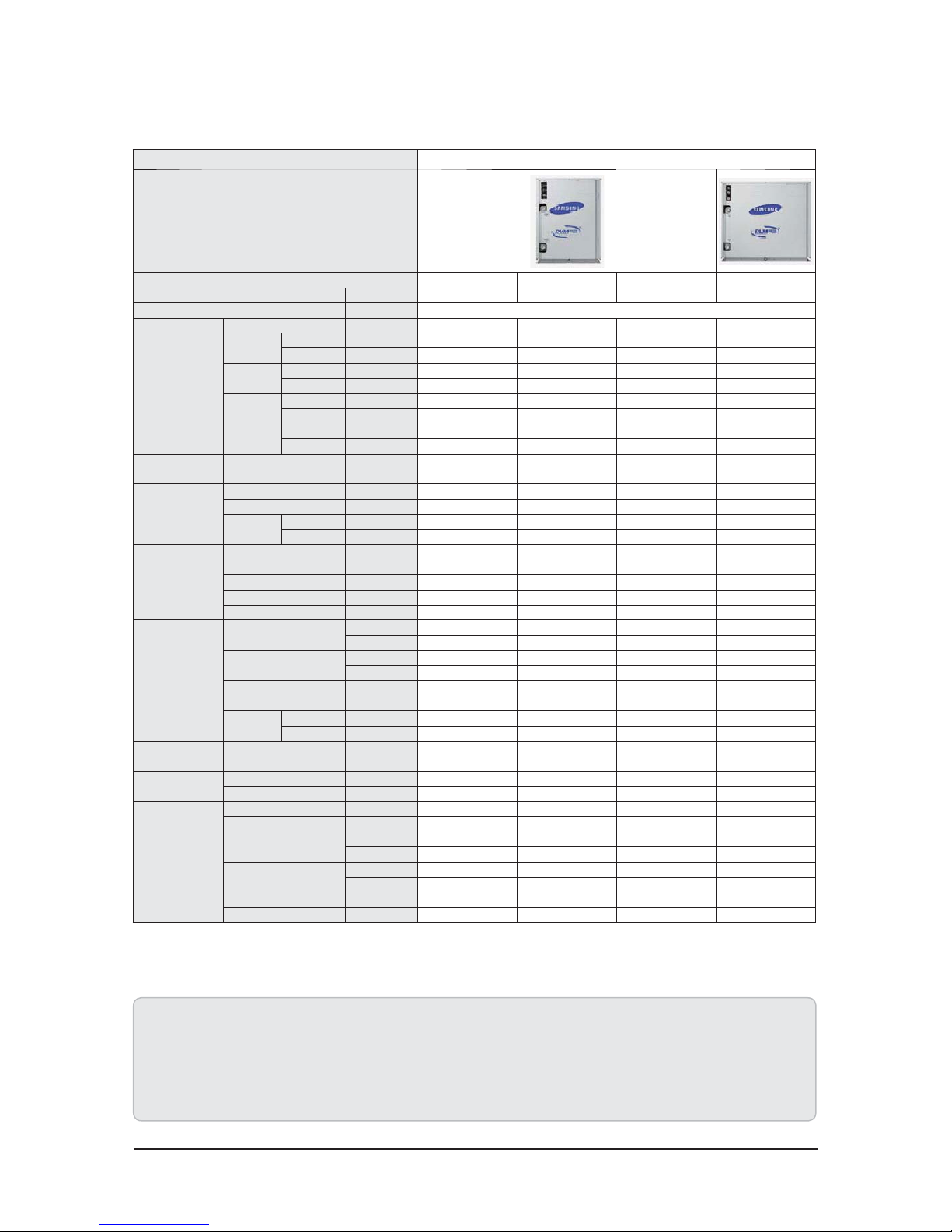
2-2 Product Specifications
2-2-1 Outdoor Unit
1. Proper form capacity standard of air conditioning
- Cooling capacity : It is figures that appear in indoor 80.6 ሥ DB/66.2 ሥ WB, outdoor 95 ሥ DB, length 50m of piping, fall 0m standard.
- Heating capacity : It is figures that appear in indoor 68 ሥ DB, outdoor 44.6 ሥ DB, length 50m of piping, fall 0ft standard.
2. If proper form heating capacity is outdoor temperature 44.6 ሥ standard and outdoor temperature goes down by below zero,
heating capacity can drop according to temperature condition.
3. Need special load calculation in case of use by main heating in the winter, and please buy product for low temperature that heating effect excels at low temperature.
4. Maximum length between outdoor and indoor units allows up to 656ft (Equivalent length 722ft).
5. If the indoor unit is below, height length allows up to 361ft (If over 164ft, decide whether to install the PDM kit). If the outdoor unit is below, allowable height length is 131ft.
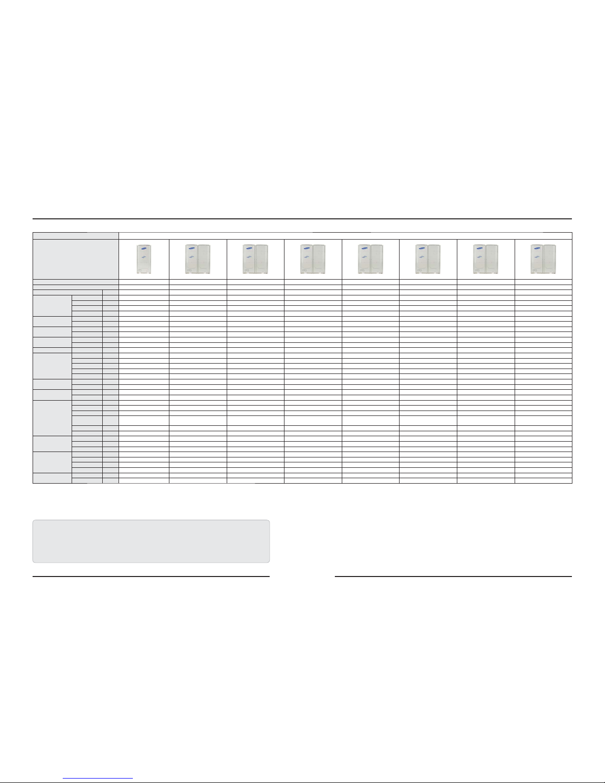
TYPE DVM S HP - 208-230V
Model
AM072FXVAFH
6
AM096FXVAFH
6
AM120FXVAFH
6
AM144FXVAFH
6
AM168HXVAFH
6
AM192HXVAFH
6
AM072KXVTF
6
AM096KXVTF
6
Mode HP HP HP HP HP HP HP HP
Power Ø,V,Hz 3/208-230/60 3/208-230/60 3/208-230/60 3/208-230/60 3/208-230/60 3/208-230/60 3/208-230/60 3/208-230/60
Capacity
Cooling (Nominal) Btu/h 72,000 96,000 120,000 144,000 168,000 192,000 72,000 96,000
Cooling (Rated) Btu/h 69,000 92,000 114,000 138,000 160,000 184,000 69,000 92,000
Heating (Nominal) Btu/h 81,000 108,000 135,000 162,000 189,000 216,000 81,000 108,000
Heating (Rated) Btu/h 77,000 103,000 129,000 154,000 180,000 206,000 77,000 103,000
Power Consumption
(Nonducted, AHRI)
Cooling W 5,350 6,680 9,140 12,340 14,680 17,360 4,450 5,940
Heating W 5,430 7,130 9,520 12,400 14,460 17,250 5,010 6,490
current consumption
(Nonducted, AHRI)
Cooling A 14.6 18.2 24.9 33.7 40.05 47.37 12.1 16.2
Heating A 14.8 19.5 26.0 33.8 39.45 47.07 13.7 17.7
EER
(Nonducted, AHRI)
Cooling Btu/Wh 12.9 13.8 12.5 11.2 11.4 11.1 15.5 15.5
Heating W/W 4.15 4.23 3.97 3.64 3.83 3.67 4.50 4.65
IEER(AHRI) Cooling W/W 23.0 26.0 24.2 22.7 24.5 23.0 40.0 37.0
Compressor
Model - DS-GB052FBVASG DS-GB052FBVASG DS-GB052FBVASG DS-GB052FBVASG DS-GB052FBVASG DS4GJ5066EVASG DS-GB052FBVASG DS4GJ5066EVASG
Output kW 5.18 5.18 5.18 5.18 5.18 6.45 5.18 6.45
Excluded Volume cc/rev 52.0 52.0 52.0 52.0 52.0 66.0 52.0 66.0
Capacity Btu/h 58,500 58,500 58,500 58,500 58,500 73,500 58,500 73,500
Quantity EA 1 2 2 2 2 2 2 2
Lubricant oil
Type Liter FV68D(PVE) FV68D(PVE) FV68D(PVE) FV68D(PVE) FV68D(PVE) FV68D(PVE) PV68D(PVE) PV68D(PVE)
Factory Charging Liter 3.9 6.2 6.2 6.2 6.2 6.2 6.2 6.2
Refrigerant
Type - R410A R410A R410A R410A R410A R410A R410A R410A
Factory Charging lb 12.13 16.31 16.31 19.18 24.30 24.30 18.5 18.5
FAN
Ø mm 700 575 575 575 575 575 575 575
MAX STEP - 19 29 29 31 35 35 28 29
CODE - DB31-00298A DB94-03285B DB94-03285B DB94-03285B DB94-03285B DB94-03285B DB94-03285B DB94-03285B
MAX RPM
STEP
(RPM)
800 1050 1050 1100 1200 1200 1000 1050
QuantityEA12222222
Airow CMM 205 260 260 270 310 310 240 260
Piping
Connections
Gas Inch 3/4"(19.05) 7/8"(22.22) 1+1/8"(28.58) 1+1/8"(28.58) 1+1/8"(28.58) 1+1/8"(28.58) 1+1/8"(28.58) 1+1/8"(28.58)
Dis. Gas Inch - - - - - - - -
Liquid Inch 3/8"(9.52) 3/8"(9.52) 1/2"(12.7) 1/2"(12.7) 5/8"(15.88) 5/8"(15.88) 1/2"(12.7) 1/2"(12.7)
DIMENSION
NET mm 880x1695x765 1295x1695x765 1295x1695x765 1295x1695x765 1295x1695x765 1295x1695x765 1295x1695x765 1295x1695x765
GROSS mm 948x1887x832 1363x1887x832 1363x1887x832 1363x 1887 x832 1363x1887x832 1363x1887x832 1363x1887x832 1363x1887x832
NET kg 190 278 278 293 325 333 298 333
GROSS kg 206 300 300 312 342 350 317 350
Operating Temp.
Range
Cooling
ሥ
23~118 23~118 23~118 23~118 23~118 23~118 23~118 23~118
Heating
ሥ
-13~75 -13~75 -13~75 -13~75 -13~75 -13~75 -13~75 -13~75

2-17 Samsung Electronics
Outdoor Unit(Continue)
1. Proper form capacity standard of air conditioning
- Cooling capacity : It is figures that appear in indoor 80.6 ሥ DB/66.2 ሥ WB, outdoor 95 ሥ DB, length 50m of piping, fall 0m standard.
- Heating capacity : It is figures that appear in indoor 68 ሥ DB, outdoor 44.6 ሥ DB, length 50m of piping, fall 0ft standard.
2. If proper form heating capacity is outdoor temperature 44.6 ሥ standard and outdoor temperature goes down by below zero,
heating capacity can drop according to temperature condition.
3. Need special load calculation in case of use by main heating in the winter, and please buy product for low temperature that heating effect excels at low temperature.
4. Maximum length between outdoor and indoor units allows up to 656ft (Equivalent length 722ft).
5. If the indoor unit is below, height length allows up to 361ft (If over 164ft, decide whether to install the PDM kit). If the outdoor unit is below, allowable height length is 131ft.
TYPE DVM S HR - 208-230V
Model
AM072FXVAFR6AM096FXVAFR6AM120FXVAFR6AM144FXVAFR6AM168HXVAFR6AM192HXVAFR
6
Mode
HR HR HR HR HR HR
Power Ø,V,Hz
3/208-230/60 3/208-230/60 3/208-230/60 3/208-230/60 3/208-230/60 3/208-230/60
Capacity
Cooling (Nominal) Btu/h
72,000 96,000 120,000 144,000 168,000 192,000
Cooling (Rated) Btu/h
69,000 92,000 114,000 138,000 160,000 184,000
Heating (Nominal) Btu/h
81,000 108,000 135,000 162,000 189,000 216,000
Heating (Rated) Btu/h
77,000 103,000 129,000 154,000 180,000 206,000
Power Con-
sumption
(Nonducted,
AHRI)
Cooling W
5,350 6,680 9,140 12,340 14,680 17,360
Heating W
5,430 7,130 9,520 12,400 14,460 17,250
current con-
sumption
(Nonducted,
AHRI)
Cooling A
14.6 18.2 24.9 33.7 40.05 47.37
Heating A
14.8 19.5 26.0 33.8 39.45 47.07
EER
(Nonducted,
AHRI)
Cooling Btu/Wh
12.9 13.8 12.5 11.2 11.4 11.1
Heating W/W
4.15 4.23 3.97 3.64 3.83 3.67
IEER(AHRI) Cooling W/W
23.0 26.0 24.2 22.7 24.5 23.0
Compressor
Model -
DS-GB052FBVASG DS-GB052FBVASG DS- GB052FBVASG DS-GB052FBVASG DS-GB052FBVASG DS4GJ5066E VASG
Output kW
5.18 5.18 5.18 5.18 5.18 6.45
Excluded Volume cc/rev
52.0 52.0 52.0 52.0 52.0 66.0
Capacity Btu/h
58,500 58,500 58,500 58,500 58,500 73,500
Quantity EA
1 2 2 2 2 2
Lubricant oil
Type Liter
FV68D(PVE) FV68D(PVE) FV68D(PVE) FV68D(PVE) FV68D(PVE) FV68D(PVE)
Factory Charging Liter
3.9 6.2 6.2 6.2 6.2 6.2
Refrigerant
Type -
R410A R410A R410A R410A R410A R410A
Factory Charging lb
12.13 16.31 16.31 19.18 24.30 24.30
FAN
Ømm
700 575 575 575 575 575
MAX STEP -
19 29 29 31 35 35
CODE -
DB31-00298A DB94-03285B DB94-03285B DB94-03285B DB94-03285B DB94-03285B
MAX RPM
STEP
(RPM)
800 1050 1050 1100 1200 1200
Quantity EA
122222
Airow CMM
205 260 260 270 310 310
Piping
Connections
Gas Inch
3/4"(19.05) 7/8"(22.22) 1+1/8"(28.58) 1+1/8"(28.58) 1+1/8"(28.58) 1+1/8"(28.58)
Dis. Gas Inch
5/8"(15.88) 3/4"(19.05) 7/8"(22.22) 7/8"(22.22) 1+1/8"(28.58) 1+1/8"(28.58)
Liquid Inch
3/8"(9.52) 3/8"(9.52) 1/2"(12.7) 1/2"(12.7) 5/8"(15.88) 5/8"(15.88)
DIMENSION
NET mm
880x1695x765 1295x1695x765 1295x1695x765 1295x1695x765 1295x1695x765 1295x1695x765
GROSS mm
948x1887x832 1363x1887x832 1363x1887x832 1363x1887x832 1363x1887x832 1363x1887x832
NET kg
195 284 284 299 332 340
GROSS kg
211 303 303 318 349 357
Operating Temp.
Range
Cooling
ሥ
23~118 23~118 23~118 23~118 23~118 23~118
Heating
ሥ
-13~75 -13~75 -13~75 -13~75 -13~75 -13~75
Product Specications
2-18 Samsung Electronics
Product Specications
Samsung Electronics 2-19
Outdoor Unit(Continue)
1. Proper form capacity standard of air conditioning
- Cooling capacity : It is figures that appear in indoor 80.6 ሥ DB/66.2 ሥ WB, outdoor 95 ሥ DB, length 50m of piping, fall 0m standard.
- Heating capacity : It is figures that appear in indoor 68 ሥ DB, outdoor 44.6 ሥ DB, length 50m of piping, fall 0ft standard.
2. If proper form heating capacity is outdoor temperature 44.6 ሥ standard and outdoor temperature goes down by below zero,
heating capacity can drop according to temperature condition.
3. Need special load calculation in case of use by main heating in the winter, and please buy product for low temperature that heating effect excels at low temperature.
4. Maximum length between outdoor and indoor units allows up to 656ft (Equivalent length 722ft).
5. If the indoor unit is below, height length allows up to 361ft (If over 164ft, decide whether to install the PDM kit). If the outdoor unit is below, allowable height length is 131ft.
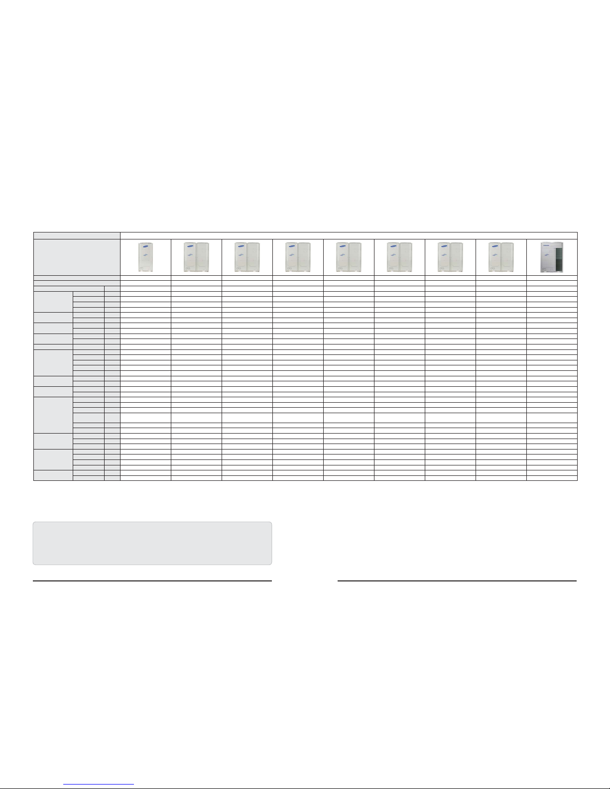
TYPE DVM S HP - 460V
Model
AM072FXVAJH
6
AM096FXVAJH
6
AM120FXVAJH
6
AM144FXVAJH
6
AM168HXVAJH
6
AM192HXVAJH
6
AM072KXVTJ
6
AM096KXVTJ
6 AM216KX VGJH/AA
Mode HP HP HP HP HP HP HP HP HP
Power Ø,V,Hz 3/460/60 3/460/60 3/460/60 3/460/60 3/460/60 3/460/60 3/460/60 3/460/60 3/460/60
Capacity
Cooling (Nominal) Btu/h 72,000 96,000 120,000 144,000 168,000 192,000 72,000 96,000 216,000
Cooling (Rated) Btu/h 69,000 92,000 114,000 138,000 160,000 184,000 69,000 92,000 206,000
Heating (Nominal) Btu/h 81,000 108,000 135,000 162,000 189,000 216,000 81,000 108,000 243,000
Heating (Rated) Btu/h 77,000 103,000 129,000 154,000 180,000 206,000 77,000 103,000 230,000
Power Consumption
(Nonducted, AHRI)
Cooling W 5,350 6,600 9,190 12,340 14,680 17,360 4,450 5,940 18,400
Heating W 5,430 7,130 9,520 12,400 14,460 17,250 5,010 6,490 16,440
current consumption
(Nonducted, AHRI)
Cooling A 7.3 9.0 12.5 16.8 20.03 23.68 6.1 8.1 25.1
Heating A 7.4 9.7 13.0 16.9 19.73 23.53 6.8 8.9 22.4
EER
(Nonducted, AHRI)
Cooling Btu/Wh 12.9 13.9 12.4 11.2 11.4 11.1 15.5 15.5 11.2
Heating W/W 4.15 4.23 3.97 3.64 3.83 3.67 4.50 4.65 4.1
IEER(AHRI) Cooling W/W 23.0 24.2 23.0 22.7 24.5 23.0 40.0 37.0 25.5
Compressor
Model - DS-GB052FAVBSG DS-GB052FAVBSG DS-GB052FAVBSG DS-GB052FAVBSG DS-GB052FAVBSG DS-GB066FAVBSG DS-GB052FAVBSG DS- GB066FAVBSG DS-GB066FAVB
Output kW 5.18 5.18 5.18 5.18 5.18 6.39 5.18 6.39 6.39
Excluded Volume cc/rev 52.0 65.8 65.8 52.0 52.0 66.0 52.0 66.0 66.0
Capacity Btu/h 58,500 58,500 58,500 58,500 58,500 73,500 58,500 73,500 73,500
Quantity EA 1 2 2 2 2 2 2 2 2
Lubricant oil
Type Liter FV68D(PVE) FV68D(PVE) FV68D(PVE) FV68D(PVE) FV68D(PVE) FV68D(PVE) PV68D(PVE) PV68D(PVE) PV68D(PVE)
Factory Charging Liter 3.9 6.2 6.2 6.2 6.2 6.2 6.2 6.2 6.2
Refrigerant
Type - R410A R410A R410A R410A R410A R410A R410A R410A R410A
Factory Charging lb 12.13 16.31 16.31 19.18 24.30 24.30 18.5 18.5 27.6
FAN
Ø mm 700 575 575 575 575 575 575 575 575
MAX STEP - 19 29 29 31 35 35 28 29 35
CODE - DB31-00298A DB94-03285B DB94-03285B DB94-03285B DB94-03285B DB94-03285B DB94-03285B DB94-03285B DB94-03285A
MAX RPM
STEP
(RPM)
800 1050 1050 1100 1200 1200 1000 1050 1200
Quantity EA 1 2 2 2 2 2 2 2 2
Airow CMM 205 260 260 270 310 310 240 260 340
Piping
Connections
Gas Inch 3/4"(19.05) 7/8"(22.22) 1+1/8"(28.58) 1+1/8"(28.58) 1+1/8"(28.58) 1+1/8"(28.58) 1+1/8"(28.58) 1+1/8"(28.58) 1+1/8"(28.58)
Dis. Gas Inch - - - - - - - - -
Liquid Inch 3/8"(9.52) 3/8"(9.52) 1/2"(12.7) 1/2"(12.7) 5/8"(15.88) 5/8"(15.88) 1/2"(12.7) 1/2"(12.7) 5/8"(15.88)
DIMENSION
NET mm 880x1695x765 1295x1695x765 1295x1695x765 1295x1695x765 1295x1695x765 1295x1695x765 1295x1695x765 1295x1695x765 1295x1795x765
GROSS mm 948x1887x832 1363x1887x832 1363x1887x832 1363x1887x832 1363x1887x832 1363x1887x832 1363x1887x832 1363x1887x832 1363x1987x832
NET kg 190 278 278 293 326 334 305 334 340
GROSS kg 206 300 300 312 343 351 324 351 362
Operating Temp.
Range
Cooling
ሥ
23~118 23~118 23~118 23~118 23~118 23~118 23~118 23~118 23~118
Heating
ሥ
-13~75 -13~75 -13~75 -13~75 -13~75 -13~75 -13~75 -13~75 -13~75
Product Specications
Samsung Electronics 2-20
Outdoor Unit(Continue)
TYPE DVM S HR - 460V
Model
AM072FXVAJR6AM096FXVAJR6AM120FXVAJR6AM144FXVAJR6AM168HXVAJR6AM192HXVAJR
6
Mode
HR HR HR HR HR HR
Power Ø,V,Hz
3/460/60 3/460/60 3/460/60 3/460/60 3/460/60 3/460/60
Capacity
Cooling (Nominal) Btu/h
72,000 96,000 120,000 144,000 168,000 192,000
Cooling (Rated) Btu/h
69,000 92,000 114,000 138,000 160,000 184,000
Heating (Nominal) Btu/h
81,000 108,000 135,000 162,000 189,000 216,000
Heating (Rated) Btu/h
77,000 103,000 129,000 154,000 180,000 206,000
Power Con-
sumption
(Nonducted,
AHRI)
Cooling W
5,350 6,600 9,190 12,340 14,680 17,360
Heating W
5,430 7,130 9,520 12,400 14,460 17,250
current con-
sumption
(Nonducted,
AHRI)
Cooling A
7.3 9.0 12.5 16.8 20.03 23.68
Heating A
7.4 9.7 13.0 16.9 19.73 23.53
EER
(Nonducted,
AHRI)
Cooling Btu/Wh
12.9 13.9 12.4 11.2 11.4 11.1
Heating W/W
4.15 4.23 3.97 3.64 3.83 3.67
IEER(AHRI) Cooling W/W
23.0 24.2 23.0 22.7 24.5 23.0
Compressor
Model -
DS-GB052FAVBSG DS-GB052FAVBSG DS-GB052FAVBSG DS- GB052FAVBSG DS-GB052FAVBSG DS-GB066FAVBSG
Output kW
5.18 5.18 5.18 5.18 5.18 6.39
Excluded Volume cc/rev
52.0 65.8 65.8 52.0 52.0 66.0
Capacity Btu/h
58,500 58,500 58,500 58,500 58,500 73,500
Quantity EA
1 2 2 2 2 2
Lubricant oil
Type Liter
FV68D(PVE) FV68D(PVE) FV68D(PVE) FV68D(PVE) FV68D(PVE) FV68D(PVE)
Factory Charging Liter
3.9 6.2 6.2 6.2 6.2 6.2
Refrigerant
Type -
R410A R410A R410A R410A R410A R410A
Factory Charging lb
12.13 16.31 16.31 19.18 24.30 24.30
FAN
Ømm
700 575 575 575 575 575
MAX STEP -
19 29 29 31 35 35
CODE -
DB31-00298A DB94-03285B DB94-03285B DB94-03285B DB94-03285B DB94-03285B
MAX RPM
STEP
(RPM)
800 1050 1050 1100 1200 1200
Quantity EA
122222
Airow CMM
205 260 260 270 310 310
Piping
Connections
Gas Inch
3/4"(19.05) 7/8"(22.22) 1+1/8"(28.58) 1+1/8"(28.58) 1+1/8"(28.58) 1+1/8"(28.58)
Dis. Gas Inch
5/8"(15.88) 3/4"(19.05) 7/8"(22.22) 7/8"(22.22) 1+1/8"(28.58) 1+1/8"(28.58)
Liquid Inch
3/8"(9.52) 3/8"(9.52) 1/2"(12.7) 1/2"(12.7) 5/8"(15.88) 5/8"(15.88)
DIMENSION
NET mm
880x1695x765 1295x1695x765 1295x1695x765 1295x1695x765 1295x1695x765 1295x1695x765
GROSS mm
948x1887x832 1363x1887x832 1363x1887x832 1363x1887x832 1363x1887x832 1363x1887x832
NET kg
195 284 284 299 333 341
GROSS kg
211 303 303 318 350 358
Operating Temp.
Range
Cooling
ሥ
23~118 23~118 23~118 23~118 23~118 23~118
Heating
ሥ
-13~75 -13~75 -13~75 -13~75 -13~75 -13~75
1. Proper form capacity standard of air conditioning
- Cooling capacity : It is figures that appear in indoor 80.6 ሥ DB/66.2 ሥ WB, outdoor 95 ሥ DB, length 50m of piping, fall 0m standard.
- Heating capacity : It is figures that appear in indoor 68 ሥ DB, outdoor 44.6 ሥ DB, length 50m of piping, fall 0ft standard.
2. If proper form heating capacity is outdoor temperature 44.6 ሥ standard and outdoor temperature goes down by below zero,
heating capacity can drop according to temperature condition.
3. Need special load calculation in case of use by main heating in the winter, and please buy product for low temperature that heating effect excels at low temperature.
4. Maximum length between outdoor and indoor units allows up to 656ft (Equivalent length 722ft).
5. If the indoor unit is below, height length allows up to 361ft (If over 164ft, decide whether to install the PDM kit). If the outdoor unit is below, allowable height length is 131ft.

Product Specications
2-21 Samsung Electronics
Product Specications
Samsung Electronics 2-22
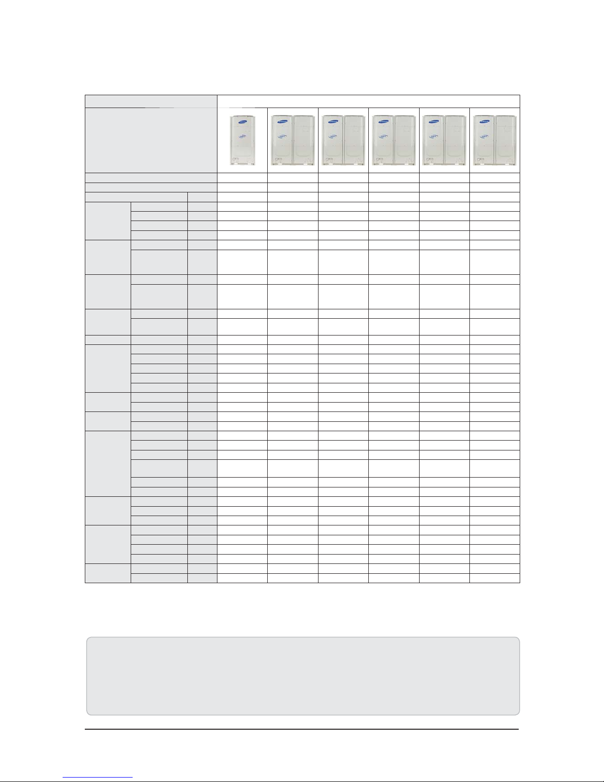
TYPE DVM S Water 208-230V
Model Name(Samsung Model)
AM038KXWDCH/AA AM048KXWDCH/AA AM055KXWDCH/AA AM072HXWAFR/AA AM096HXWAFR/AA AM120HXWAFR/AA AM192HXWAFR/AA
Mode-HPHPHPHRHRHRHR
Power Supply Φ, V, Hz 1Φ,208~230V,60Hz 3Φ,208~230V,60Hz
Performance
TonTon345681016
Capacity
(Nominal)
Cooling Btu/h 38200 47800 54600 72,000 96,000 120,000 192,000
Heating 42600 54600 61400 81,000 108,000 135,000 216,000
Capacity
(Rated)
Cooling Btu/h 38000 48000 54500 69,000 92,000 114,000 184,000
Heating 42000 54000 61000 77,000 103,000 129,000 206,000
Eciency
Ratings
EER Btu/W*h 15 16.2 14.7 20.20 19.90 12.80 11.60
IEER Btu/W*h 28 28 26 30.10 28.60 22.20 18.30
COP W/W 5.7 5.6 5.4 6.00 5.90 4.40 4.30
SCHE Btu/W*h - - - 26.50 27.40 17.80 20.20
Power
MCA A 20 24 26 16.0 23.0 30.0 39.6
MOP 35 40 45 25 40 50 50
Compressor
Type - Rotary Inverter Rotary Inverter Rotary I nverter SSC Scroll x 1 SSC Scroll x 1 SSC Scroll x 1 SSC Scroll x 2
Output kW × n 2.82 4.11 4.11 4.96 4.96 4.96 4.96 x 2
Oil
Type - PVE PVE PVE PVE PVE PVE PVE
Initial Charge Liter 1.2 1.7 1.7 3.9 3.9 3.9 6.2
Condenser
Type - Plate Heat Exchanger Plate Heat Exchanger Plate Heat Exchanger Plate Heat Exchanger Plate Heat Exchanger Plate Heat Exchanger Plate Heat Exchanger
Pipe Size(Female Thread) Φ, inch 1-1/4 FPT 1-1/4 FPT 1-1/4 FPT 1-1/4 FPT 1-1/4 FPT 1-1/4 FPT 1-1/4 FPT
Lost Head kPa (ftAq) 25(8.4) 20(6.7) 28(9.4) 22(7.3) 30(10.0) 43(14.4) 54(18.1)
Water Flow Rate LPM(GPM) 40(10.5) 50(13.2) 60(15.8) 80(21.1) 96(25.4) 114(30.1) 190(50.2)
Water Max. Pressure Mpa(Psi) 1.96(285) 1.96(285) 1.96(285) 1.96(285) 1.96(285) 1.96(285) 1.96(285)
Piping
Connections
Liquid Pipe
Φ, mm------Φ, inch 3/8 3/8 3/8 3/8 3/8 1/2 5/8
Gas Pipe
Φ, mm------Φ, inch 5/8 3/4 3/4 3/4 7/8 1-1/8 1-1/8
Discharge Gas Pipe
Φ, mm------Φ, inch - - - 5/8 3/4 3/4 1-1/8
Installation
Limitation
Max. Length m (ft) 75(246) 75(246) 75(246) 170(558) 170(558) 170(558) 170(558)
Max. Height m (ft) 30(98) 30(98) 30(98) 50(164) 50(164) 50(164) 50(164)
Refrigerant
Type - R410A R410A R410A R410A R410A R410A R410A
Factory Charging kg (lbs) 1.1(2.4) 1.6(3.5) 1.6(3.5) 5.5(12.1) 5.8(12.8) 6(13.2) 9.8(21.6)
Sound
Sound Pressure dB(A) 47 48 49 48 48 50 51
Sound Power 70 70 70 73
External
Dimension
Net Weight kg (lbs) 73(161) 87(191) 87(191) 160(353) 160(353) 160(353) 240(529)
Shipping Weight kg (lbs) 80(176) 94(207) 94(207) 167(368) 167(368) 167(368) 250(551)
Net Dimensions (WxHxD)
mm 750x800x330 750x800x330 750x800x330 770x1000x545 770x1000x545 770x1000x545 1100x1000x545
Inch 29.5x31.5x13.0 29.5x31.5x13.0 29.5x31.5x13.0 30.3x39.4x21.5 30.3x39.4x21.5 30.3x39.4x21.5 43.3x39.4x21.5
Shipping Dimensions (Wx-
HxD)
mm 812x950x392 812x950x392 812x950x392 840x1200x620 840x1200x620 840x1200x620 1170x1200x620
Inch 31.9x37.4x15.4 31.9x37.4x15.4 31.9x37.4x15.4 33.1x47.2x24.4 33.1x47.2x24.4 33.1x47.2x24.4 46.1x47.2x24.4
Operating
Temp. Range(Water)
Cooling
ఁሥ
10~45(50~113) 10~45(50~113) 10~45(50~113) 10~45(50~113) 10~45(50~113) 10~45(50~113) 10~45(50~113)
Heating
ఁሥ
10~45(50~113) 10~45(50~113) 10~45(50~113) 10~45(50~113) 10~45(50~113) 10~45(50~113) 10~45(50~113)
Product Specications
2-23 Samsung Electronics
Outdoor Unit(Continue)
TYPE DVM S Water 460V
Model Name(Samsung Model) AM072HXWAJR/AA AM096HXWAJR/AA AM120HXWAJR/AA AM192HXWAJR/AA
Mode -HRHRHRHR
Power Supply Φ, V, Hz 3Φ,460V,60Hz
Performance
Ton Ton 6 8 10 16
Capacity
(Nominal)
Cooling Btu/h 72,000 96,000 120,000 192,000
Heating 81,000 108,000 135,000 216,000
Capacity
(Rated)
Cooling Btu/h 69,000 92,000 114,000 184,000
Heating 77,000 103,000 129,000 206,000
Eciency
Ratings
EER Btu/W*h 20.20 19.90 15.40 11.60
IEER Btu/W*h 30.10 28.60 25.30 18.30
COP W/W 6.00 5.90 4.80 4.30
SCHE Btu/W*h 26.50 27.40 20.30 20.20
Power
MCA A 10.0 11.0 15.6 26.2
MOP
15 15 25 35
Compressor
Type - SSC Scroll x 1 SSC Scroll x 1 SSC Scroll x 1 SSC Scroll x 2
Output kW × n 4.96 4.96 6.13 4.96 x 2
Oil
Type - PVE PVE PVE PVE
Initial Charge Liter 3.9 3.9 3 .9 6.2
Condenser
Type - Plate Heat Exchanger Plate Heat Exchanger Plate Heat Exchanger Plate Heat Exchanger
Pipe Size(Female Thread) Φ, inch 1-1/4 FPT 1-1/4 FPT 1-1/4 FPT 1-1/4 FPT
Lost Head kPa (ftAq) 22(7.3) 30(10.0) 43(14.4) 54(18.1)
Water Flow Rate LPM(GPM) 80(21.1) 96(25.4) 114(30.1) 190(50.2)
Water Max. Pressure M pa(Psi) 1.96(285) 1.96(285) 1.96(285) 1.96(285)
Piping
Connections
Liquid Pipe
Φ, mm---Φ, inch 3 /8 3/8 1/2 5/8
Gas Pipe
Φ, mm---Φ, inch 3 /4 7/8 1-1/8 1-1/8
Discharge Gas Pipe
Φ, mm---Φ, inch 5 /8 3/4 3/4 1-1/8
Installation
Limitation
Max. Length m (ft) 170(558) 170(558) 170(558) 170(558)
Max. Height m (ft) 50(164) 50(164) 50(164) 50(164)
Refrigerant
Type - R410A R410A R410A R410A
Factory Charging kg (lbs) 5.5(12.1) 5.8(12.8) 6(13.2) 9.8(21.6)
Sound
Sound Pressure dB(A) 48 48 50 5 1
Sound Power 70 7 0 70 73
External
Dimension
Net Weight kg (lbs) 167(368) 167(368) 167(368) 247(545)
Shipping Weight kg (lbs) 174(384) 174(384) 174(384) 257(567)
Net Dimensions (WxHxD)
mm 790x1000x545 790x1000x545 790x1000x545 1120x1000x545
Inch 31.1x39.4x21.5 31.1x39.4x21.5 31.1x39.4x21.5 44.1x39.4x21.5
Shipping Dimensions (Wx-
HxD)
mm 840x1200x620 840x1200x620 840x1200x620 1170x1200x620
Inch 33.1x47.2x24.4 33.1x47.2x24.4 33.1x47.2x24.4 46.1x47.2x24.4
Operating
Temp. Range(Water)
Cooling
ఁሥ
10~45(50~113) 10~45(50~113) 10~45(50~113) 10~45(50~113)
Heating
ఁሥ
10~45(50~113) 10~45(50~113) 10~45(50~113) 10~45(50~113)
1. Proper form capacity standard of air conditioning
- Cooling capacity : It is figures that appear in indoor 80.6 ሥ DB/66.2 ሥ WB, outdoor 95 ሥ DB, length 50m of piping, fall 0m standard.
- Heating capacity : It is figures that appear in indoor 68 ሥ DB, outdoor 44.6 ሥ DB, length 50m of piping, fall 0ft standard.
2. If proper form heating capacity is outdoor temperature 44.6 ሥ standard and outdoor temperature goes down by below zero,
heating capacity can drop according to temperature condition.
3. Need special load calculation in case of use by main heating in the winter, and please buy product for low temperature that heating effect excels at low temperature.
4. Maximum length between outdoor and indoor units allows up to 656ft (Equivalent length 722ft).
5. If the indoor unit is below, height length allows up to 361ft (If over 164ft, decide whether to install the PDM kit). If the outdoor unit is below, allowable height length is 131ft.

Product Specications
Samsung Electronics 2-24
2-3 Accessory and Option Specifications
2-3-1 Accessories
Picture Classification Model Name Remark
Y-Joint
MXJ-YA1509M
15.0 kW and below
MXJ-YA2512M
Over 15.0 kW~40.6 kW and below
MXJ-YA2812M
Over 40.6 kW~46.4 kW and below
MXJ-YA2815M
Over 46.4 kW~69.6 kW and below
MXJ-YA3419M
Over 69.6 kW~98.6 kW and below
MXJ-YA4119M
Over 98.6 kW~139.2 kW and below
MXJ-YA4422M
Over 139.2 kW
Y-Joint
(Only H/R)
MXJ-YA1500M
23.2 kW and below
MXJ-YA2500M
Over 23.2 kW~69.6 kW and below
MXJ-YA3100M
Over 69.6 kW~139.2 kW and below
MXJ-YA3800M
139.2 kW and below
Distribution header
MXJ-HA2512M
46.4 kW and below (for 4 rooms)
MXJ-HA3115M
69.6 kW and below (for 8 rooms)
MXJ-HA3819M
Over 69.6 kW (for 8 rooms)
Y-Joint -Outdoor Unit
MXJ-TA3819M
139.2 kW and below
MXJ-TA4422M
145 kW and below
Y-Joint
(Only H/R)-Outdoor Unit
MXJ-TA3100M
139.2 kW and below
MXJ-TA3800M
145 kW and Over
MCU
(Mode Control Unit)
MCU-S6NEE1N
6 ROOM
MCU-S4NEE1N
4 ROOM
MCU-S4NEE2N
2 ROOM
MCU-S2NEK1N
2 ROOM
EEV KIT (1 Room)
MEV-E24SA
Applty to products without EEV
(Wall mount & Ceiling)
MEV-E32SA
EEV KIT (2 Room)
MXD-E24K132A
MXD-E24K200A
MXD-E32K200A
MXD-E24K232A
EEV KIT (3 Room)
MXD-E24K132A
MXD-E24K300A
MXD-E32K224A
MXD-E32K300A
Samsung Electronics 3-1
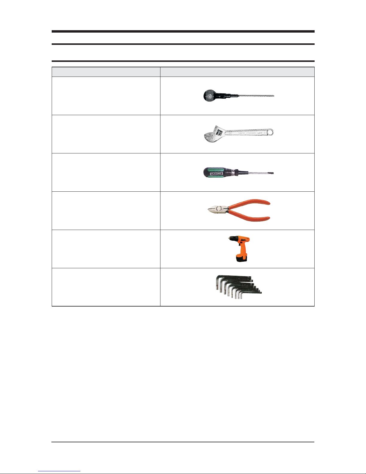
3-1 Necessary Tools
3. Disassembly and Reassembly
OFor “disassembly and assembly” DVM PLUS ዟ indoor unit, please refer to the products with the same structures.
Only those products that are not specified elsewhere are described here.
Item Remark
+SCREW DRIVER
MONKEY SPANNER
-SCREW DRIVER
NIPPER
ELECTRIC MOTION DRIVER
L-WRENCH
3-2 Samsung Electronics
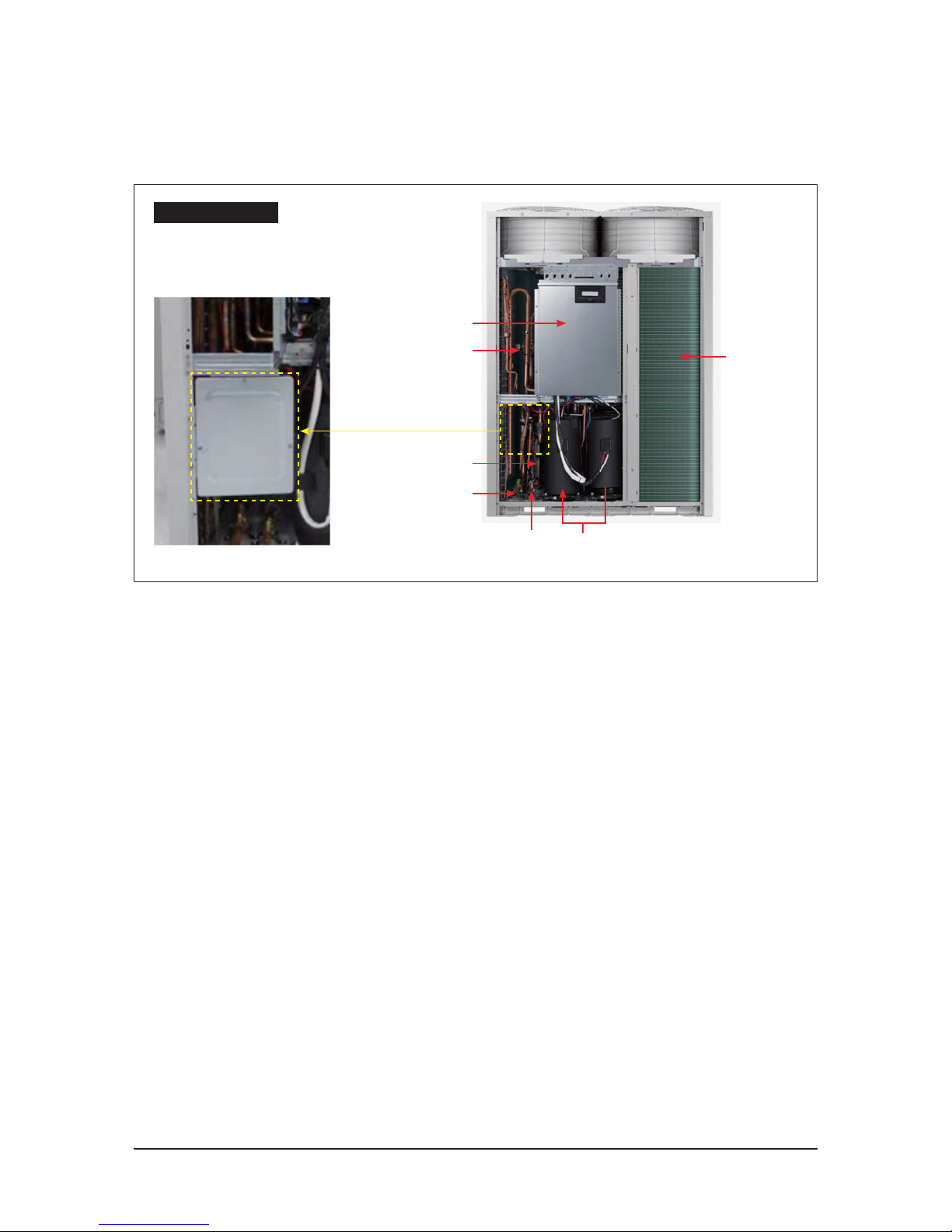
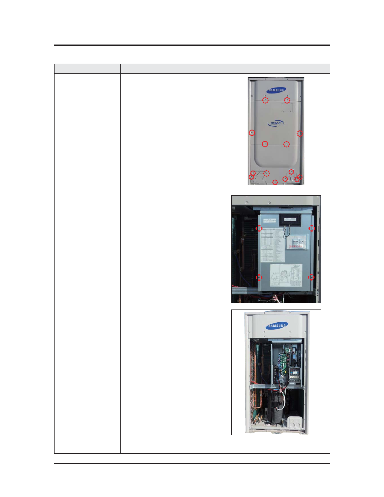
No. Parts Procedure Remark
1 Electrical
equipment Part
1) Remove 14 screws from the cabinet
(Use + screw driver)
2) Remove 4 screws that is fixing and
separate Cover Control Box.
(Use + Screw driver)
3) Power, Compressor, Valve, Motor, Sensor
connector connected to ASSY PCB
remove.
3-2 Disassembly and Reassembly
3-2-1 AM072FXVA66

Disassembly and Reassembly
Samsung Electronics 3-3
No. Parts Procedure Remark
4) 2 screws had fixed in terminal block cover
when change power terminal block, com-
munication terminal block remove.
5) 2 screws had fixed in terminal block after
remove 4 screws had fixed to Cabinet for
terminal block protection remove.
6) 5 screws had fixed to Front part remove.
 Loading...