


Service Manual
ENGLISH
Document No. CSD-SMEXG
Revision 00
Copyright MEDISON Co., LTD.
Safety Requirements
Classifications:
Type of protection against electrical shock: Class I
Degree of protection against electrical shock (Patient connection): Type BF equipment
Degree of protection against harmful ingress of water: Ordinary equipment
Degree of safety of application in the presence of a flammable anesthetic material with air or with oxygen or nitrous oxide: Equipment not suitable for use in the presence of a flammable anesthetic mixture with air or with oxygen or nitrous oxide.
Mode of operation: Continuous operation
Electromechanical safety standards met:
Medical Electrical Equipment, Part 1: General Requirements for Basic Safety and Essential Performance [IEC 60601-1:2005]
Medical Electrical Equipment, Part 1-2: General Requirements for Basic Safety and Essential Performance - Collateral Standard: Electromagnetic Compatibility - Requirements and Tests [IEC 60601-1-2:2007]
Medical Electrical Equipment, Part 1-6: General Requirements for Basic Safety and Essential PerformanceCollateral Standard: Usability [IEC 60601-1-6:2006]
Medical Electrical Equipment, Part 2-37: Particular Requirements for the Basic Safety and Essential Performance of Ultrasonic Medical Diagnostic and Monitoring Equipment [IEC60601-2-37:2007]
Medical Electrical Equipment, Part 1: General Requirements for Safety [IEC 60601-1:1988 with A1:1991 and A2:1995]
Medical Electrical Equipment, Part 1: General Requirements for Safety – 1 Collateral Standard: safety
Requirement for Medical Electrical Systems [IEC 60601-1-1:2000]
Medical Electrical Equipment, Part 1: General Requirements for Safety - 2 Collateral Standard: Electromagnetic Compatibility - Requirements and Test [IEC 60601-1-2:2001, A1:2004]
Medical Electrical Equipment, Part 1: General Requirements for Safety - 4 Collateral Standard: Programmable Electrical Medical Systems [IEC 60601-1-4: 1996, A1:1999]
Medical Electrical Equipment, Part 2: Particular Requirements for Safety - 37 Ultrasonic Medical Diagnostic and Monitoring Equipment [IEC60601-2-37: 2001 with A1:2004, A2:2005]
Medical Devices – Application of Risk Management to Medical Devices [ISO 14971:2007]
Medical Electrical Equipment, Part 1: General Requirements for Safety [UL60601-1:2003]
Medical Electrical Equipment - Part 1: General Requirements for Safety [CAN/CSA22.2 No.601.1-M90:1990, with R2003, with R2005]
Biological Evaluation of Medical Devices [ISO10993 : 2009]
Standard Means for the Reporting of theAcoustic Output of Medical Diagnostic Ultrasonic Equipment [IEC61157:2007]

Declarations:
This is CSA symbol for Canada and United States of America
This is manufacturer’s declaration of product compliance
with applicable EEC directive(s) and the European notified 0123 body.
This is manufacturer’s declaration of product compliance with applicable EEC directive(s).

READ THIS FIRST
Before asking for the product to be repaired, read this service manual thoroughly, learn how to troubleshoot, and make sure you understand the precautions fully.
The repair of the system and the replacement of parts must be carried out by an authorized dealer or the customer service department of MEDISON Co., Ltd.
The company is shall not be held liable for any injury and damage caused by not following this warning.
For safe use of this product, you should read ‘Chapter 2. Safety’ in this manual, prior to starting to useing this system.
˙ ˙ ˙ ˙ ˙ ˙
DANGER
Describes precautions necessary to prevent user hazards of great urgency. Ignoring a DANGER warning will risk life-threatening injury.
˙ ˙ ˙ ˙ ˙ ˙ ˙
WARNING
Used to indicate the presence of a hazard that can cause serious personal injury, or substantial property damage.
˙ ˙ ˙ ˙˙ ˙ ˙
CAUTION
Indicates the presence of a hazard that can cause equipment damage.
˙ ˙ ˙ ˙
NOTE
A piece of information useful for installing, operating and maintaining a system. Not related to any hazard.

Contents
Chapter 1. General Information
1.1 |
Overview ...................................................................................................... |
1-1 |
|
1.2 |
Features and Advantages of ACCUVIX XG............................................ |
1-2 |
|
1.3 |
Product Configuration................................................................................. |
1-3 |
|
|
1.3.1 |
Console............................................................................................. |
1-3 |
|
1.3.2 |
LCD Monitor ..................................................................................... |
1-4 |
|
1.3.3 |
Control Panel.................................................................................... |
1-5 |
|
1.3.4 |
Probes............................................................................................... |
1-5 |
1.4 |
Specifications............................................................................................... |
1-6 |
|
Chapter 2. Safety
2.1 |
Overview ...................................................................................................... |
2-1 |
|
2.2 |
Safety – Related Information ..................................................................... |
2-2 |
|
|
2.2.1 |
Safety Symbols ................................................................................ |
2-2 |
|
2.2.2 |
Label.................................................................................................. |
2-4 |
2.3 |
Electrical Safety........................................................................................... |
2-7 |
|
|
2.3.1 |
Prevention Electric Shock............................................................... |
2-7 |
|
2.3.2 |
ECG - Related Information ............................................................. |
2-8 |
|
2.3.3 |
ESD................................................................................................... |
2-8 |
|
2.3.4 |
EMI .................................................................................................... |
2-9 |
|
2.3.5 |
EMC .................................................................................................. |
2-9 |
2.4 |
Mechanical Safety..................................................................................... |
2-15 |
|
|
2.4.1 |
Moving Equipment......................................................................... |
2-15 |
|
2.4.2 |
Safety Note..................................................................................... |
2-16 |
2.5 |
Biological Safety........................................................................................ |
2-18 |
|
|
2.5.1 |
ALARA Principle ............................................................................ |
2-18 |
2.6 |
Environmental Protection......................................................................... |
2-30 |
|
Contents

Contents
Chapter 3. Installing the Product
3.1 |
Overview ...................................................................................................... |
3-1 |
|
3.2 |
Transportation ............................................................................................. |
3-3 |
|
|
3.2.1 |
Precautions for Transportation....................................................... |
3-3 |
|
3.2.2 |
Temperature and Humidity............................................................. |
3-3 |
|
3.2.3 Transportation of the Product......................................................... |
3-3 |
|
3.3 |
Unpacking.................................................................................................... |
3-4 |
|
|
3.3.1 |
Unpacking the Box .......................................................................... |
3-4 |
|
3.3.2 |
Checking Package Contents.......................................................... |
3-5 |
3.4 |
Precautions for Installation......................................................................... |
3-6 |
|
|
3.4.1 |
Precautions....................................................................................... |
3-6 |
|
3.4.2 |
Installation Location......................................................................... |
3-6 |
3.5 |
Installation Procedure................................................................................. |
3-7 |
|
|
3.5.1 |
Installation Safety............................................................................. |
3-7 |
|
3.5.2 Connecting the Power Cord ........................................................... |
3-8 |
|
|
3.5.3 Connecting the Network Cable ...................................................... |
3-9 |
|
|
3.5.4 Connecting the Foot switch ............................................................ |
3-9 |
|
|
3.5.5 |
Connecting the Probe...................................................................... |
3-9 |
3.6 |
Starting the Product .................................................................................. |
3-11 |
|
3.7 |
Shutting down the Product....................................................................... |
3-12 |
|
|
3.7.1 |
Power Switch.................................................................................. |
3-12 |
|
3.7.2 |
Cut-off Switch................................................................................. |
3-12 |
3.8 |
Connecting the Peripherals...................................................................... |
3-13 |
|
|
3.8.1 |
Internal Peripheral Devices........................................................... |
3-13 |
|
3.8.2 |
External Peripheral Devices ......................................................... |
3-13 |
3.9 |
System Setting .......................................................................................... |
3-15 |
|
3.10 |
General System Setup ............................................................................. |
3-16 |
|
3.11 |
Display Setup ............................................................................................ |
3-20 |
|
3.12 |
Annotate ................................................................................................. |
3-21 |
|
3.13 |
Peripherals Setup ..................................................................................... |
3-26 |
|
3.14 |
User Defined Key...................................................................................... |
3-27 |
|
3.15 |
Miscellaneous............................................................................................ |
3-29 |
|
3.16 |
Option Setup.............................................................................................. |
3-32 |
|
3.17 |
DICOM Setup............................................................................................ |
3-33 |
|
3.18 |
Auto Calc .................................................................................................. |
3-44 |
|
3.19 |
System Information................................................................................... |
3-46 |
|
3.20 |
Utility |
....................................................................................................... |
3-47 |
3.21 |
Measure Setup ........................................................................................ |
3-51 |
|
Contents

Contents
Chapter 4. Checking the Product
4.1 |
Overview ...................................................................................................... |
4-1 |
|
4.2 |
Starting the Product .................................................................................... |
4-2 |
|
4.3 |
Monitor.......................................................................................................... |
4-3 |
|
|
4.3.1 |
Monitor Display ............................................................................... |
4-4 |
4.4 |
Control Panel............................................................................................... |
4-5 |
|
|
4.4.1 |
Detail Control Panel......................................................................... |
4-6 |
|
4.4.2 |
Alphanumeric Keyboard ................................................................. |
4-9 |
|
4.4.3 |
Touch Panel ..................................................................................... |
4-9 |
4.5 |
Checking the Performance ...................................................................... |
4-11 |
|
|
4.5.1 |
Basic Check.................................................................................... |
4-11 |
|
4.5.2 |
Detail Check ................................................................................... |
4-12 |
Contents

Contents
Chapter 5. Product Structure
5.1 |
Overview ...................................................................................................... |
5-1 |
|
5.2 |
System Block Diagram............................................................................... |
5-3 |
|
5.3 |
Basic Structure of ACCUVIX XG .............................................................. |
5-4 |
|
|
5.3.1 |
Overview........................................................................................... |
5-4 |
|
5.3.2 |
Ultrasound System Part.................................................................. |
5-4 |
|
5.3.3 |
PC Part.............................................................................................. |
5-5 |
|
5.3.4 |
User Interface Part........................................................................... |
5-5 |
|
5.3.5 AC to DC Power Module................................................................. |
5-5 |
|
5.4 |
PSA |
........................................................................................................... |
5-6 |
5.5 |
Beamformer Board ..................................................................................... |
5-8 |
|
5.6 |
CW Board .................................................................................................. |
5-11 |
|
5.7 |
Back End Board ........................................................................................ |
5-15 |
|
5.8 |
PCI Board .................................................................................................. |
5-18 |
|
5.9 |
DVI Board .................................................................................................. |
5-19 |
|
5.10 |
VGA Card................................................................................................... |
5-21 |
|
5.11 |
VCRIN Board............................................................................................. |
5-22 |
|
5.12 |
PC Mother Board ...................................................................................... |
5-23 |
|
5.13 |
Software DSC............................................................................................ |
5-24 |
|
5.14 |
LCD IF Board............................................................................................. |
5-26 |
|
5.15 |
Rear Board................................................................................................. |
5-28 |
|
5.17 |
Control Panel............................................................................................. |
5-29 |
|
5.16 |
Motor Control Board ................................................................................. |
5-31 |
|
5.18 |
Power Supply ............................................................................................ |
5-32 |
|
Contents
Contents
Chapter 6. Basic Maintenance
6.1 |
Overview ...................................................................................................... |
6-1 |
|
6.2 |
System Information..................................................................................... |
6-2 |
|
6.3 |
Windows Mode............................................................................................ |
6-3 |
|
6.4 |
Upgrade ....................................................................................................... |
6-4 |
|
|
6.4.1 |
Software Upgrade............................................................................ |
6-4 |
|
6.4.2 |
Hardware Upgrade.......................................................................... |
6-5 |
6.5 |
Admin Mode ................................................................................................ |
6-7 |
|
|
6.5.1 |
Entering Admin Mode...................................................................... |
6-7 |
|
6.5.2 |
Admin Mode Functions ................................................................... |
6-8 |
6.6 |
Adding and Deleting Options................................................................... |
6-13 |
|
|
6.6.1 |
Option type ..................................................................................... |
6-13 |
|
6.6.2 |
Registering Options ....................................................................... |
6-14 |
|
6.6.3 |
Deleting Options............................................................................. |
6-17 |
|
6.6.4 |
Option Status.................................................................................. |
6-18 |
Contents

Contents
Chapter 7. Troubleshooting
7.1 |
Overview ...................................................................................................... |
7-1 |
7.2 |
Power ........................................................................................................... |
7-2 |
|
7.2.1 Power Failure ................................................................................. |
7-2 |
|
7.2.2 Power cannot be turned off ........................................................... |
7-2 |
|
7.2.3 Power is automatically turned off ................................................. |
7-3 |
7.3 |
Monitor.......................................................................................................... |
7-4 |
|
7.3.1 Blank Screen .................................................................................. |
7-4 |
|
7.3.2 Screen Color is Abnormal ............................................................. |
7-4 |
7.4 |
Error Messages ......................................................................................... |
7-5 |
|
7.4.1 System hangs after an error during booting ................................ |
7-5 |
|
7.4.2 System works even if error occurred ........................................... |
7-5 |
|
7.4.3 Error code ....................................................................................... |
7-5 |
7.5 |
Image ........................................................................................................... |
7-6 |
|
7.5.1 No BW Image Echo ....................................................................... |
7-6 |
|
7.5.2 No BW Mode Image Format ........................................................ |
7-6 |
|
7.5.3 Noise Link Rain over the BW Mode Image (Noise) ................... |
7-6 |
|
7.5.4 PW Doppler Mode Trouble ........................................................... |
7-7 |
|
7.5.5 CW Doppler Mode Trouble ........................................................... |
7-7 |
|
7.5.6 Color Doppler Mode Trouble ........................................................ |
7-7 |
|
7.5.7 Motion Mode Trouble .................................................................... |
7-7 |
Contents

Contents
Chapter 8. Disassembly and Reassembly
8.1 |
Overview |
...................................................................................................... |
8-1 |
8.2 |
Disassembly and Reassembly of the Body Cover.................................. |
8-4 |
|
|
8.2.1 |
Preparations .............................................................................. |
8-4 |
|
8.2.2 ..................................................................... |
Body Front Cover |
8-4 |
|
8.2.3 ...................................................................... |
Body Rear Cover |
8-5 |
|
8.2.4 ....................................................................... |
Body Top Cover |
8-6 |
|
8.2.5 ................................................................................. |
Handle AY |
8-7 |
|
8.2.6 ............................................................ |
Body Arch Front Cover |
8-8 |
|
8.2.7 ....................................... |
Body Arch Inner Right & Left Cover |
8-9 |
|
8.2.8 ............................................... |
Body Side Right & Left Cover |
8-10 |
|
8.2.9 ............................................... |
Body Skirt Right & Left Cover |
8-11 |
8.3Disassembly and Reassembly of the Ultrasound System PCB Part..8-12
|
8.4.1 |
Preparations............................................................................ |
8-12 |
|
8.4.2 |
PSA ASSY .............................................................................. |
8-14 |
|
8.4.3 |
CW Board, BF Board, BE Board, MTR Board.................... |
8-13 |
8.4 |
Disassembly and Reassembly of the LCD & ARM............................... |
8-14 |
|
|
8.4.1 |
Preparations............................................................................ |
8-14 |
|
8.4.2 |
LCD.......................................................................................... |
8-14 |
|
8.4.3 |
LCD ARM................................................................................ |
8-15 |
8.5 |
PC Part |
Disassembly and Reassembly of the................................... |
8-16 |
|
8.5.1 |
Preparations............................................................................ |
8-16 |
|
8.5.2 |
PC ASSY................................................................................. |
8-16 |
|
8.5.3 |
PCI Board, DVI Board, VCRIn Board,VGA Card ............... |
8-17 |
|
8.5.4 |
Rear Board.............................................................................. |
8-18 |
|
8.5.5 |
PC Power................................................................................ |
8-19 |
|
8.5.6 |
HDD ......................................................................................... |
8-20 |
8.6 |
Disassembly and Reassembly of the Power......................................... |
8-21 |
|
|
8.6.1 |
Preparations............................................................................ |
8-21 |
|
8.6.2 |
AC to DC Power Module....................................................... |
8-21 |
|
8.6.3 |
DC to DC Power Module....................................................... |
8-22 |
Contents

Contents
8.7 |
Disassembly and Reassembly of the User Interface Part |
....................8-23 |
|
|
8.7.1 |
Preparations............................................................................ |
8-23 |
|
8.7.2 |
Control Panel .......................................................................... |
8-23 |
|
8.7.3 |
Touch Panel............................................................................ |
8-24 |
|
8.7.4 |
Control Panel Board............................................................... |
8-25 |
|
8.7.5 |
Track Ball................................................................................. |
8-26 |
|
8.7.6 |
Alpha-Numeric Board ............................................................ |
8-27 |
|
8.7.7 |
LCD IF Board.......................................................................... |
8-28 |
|
8.7.8 |
DVD ......................................................................................... |
8-29 |
|
8.7.9 |
Speaker Right & Left.............................................................. |
8-30 |
|
8.7.10 |
ECG Module ........................................................................... |
8-31 |
8.8 |
Disassembly and Reassembly of the Rear Fan.................................... |
8-32 |
|
|
8.8.1 |
Preparations............................................................................ |
8-32 |
|
8.8.2 |
Rear Fan ................................................................................. |
8-32 |
Contents

Contents
Chapter 9. Probe
9.1 |
Overview ...................................................................................................... |
9-1 |
9.2 |
Probe List..................................................................................................... |
9-2 |
9.3 |
Thermal Index (TI Table)............................................................................ |
9-6 |
9.4 |
Ultrasound Transmission Gel .................................................................... |
9-7 |
9.5 |
Sheaths ........................................................................................................ |
9-7 |
9.6 |
Probe Precautions ...................................................................................... |
9-8 |
9.7 |
Cleaning and Disinfecting the Probe ...................................................... |
9-10 |
Chapter 10.User Maintenance
10.1 |
Overview |
........................................................................................................ |
10-1 |
10.2 |
System Maintenance.................................................................................... |
10-2 |
|
|
10.2.1 .......................................................... |
Installation Maintenance |
10-2 |
|
10.2.2 ...................................................... |
Cleaning and Disinfections |
10-3 |
|
10.2.3 ...............................................................Cleaning the Air Filter |
10-5 |
|
|
10.2.4 ................................................................... |
Fuse Replacement |
10-6 |
|
10.2.5 ...................................................................... |
Accuracy Check |
10-6 |
10.3 |
Administration .......................................................................of Information |
10-7 |
|
|
10.3.1 ............................................................... |
User Setting Back - up |
10-7 |
|
10.3.2 .................................................... |
Patient Information Back - up |
10-7 |
|
10.3.3 ..................................................................................... |
Software |
10-7 |
Chapter 11. Service Part List
11.1 |
Overview.................................................................................................... |
11-1 |
11.2 |
Body Cover................................................................................................ |
11-2 |
11.3 |
Ultrasound System Part ......................................................................... |
11-4 |
11.4 |
LCD & ARM............................................................................................... |
11-5 |
11.5 |
PC Part....................................................................................................... |
11-6 |
11.6 |
Power Part................................................................................................. |
11-8 |
11.7 |
User Interface Part.................................................................................... |
11-9 |
11.8 |
ETC Part .................................................................................................. |
11-10 |
11.9 |
Options..................................................................................................... |
11-11 |
Contents

Chapter 1. General Information
1.1 Overview
Chapter 1 contains the information necessaryto plan the Troubleshooting ofACCUVIX XG
The ACCUVIX XG is a high-resolution color ultrasound scanner with high penetration and a variety of measurement functions
Contents
1.1 |
Overview |
.................................................................................................... |
1-1 |
1.2 |
Features and Advantages of ACCUVIX XG............................................. |
1-2 |
|
1.3 |
Product Configuration................................................................................. |
1-3 |
|
|
1.3.1 |
Console ..................................................................................... |
1-3 |
|
1.3.2 |
LCD Monitor.............................................................................. |
1-4 |
|
1.3.3 |
Control Panel............................................................................ |
1-5 |
|
1.3.4 |
Probes ....................................................................................... |
1-5 |
1.4 |
Specifications............................................................................................... |
1-6 |
|
Chapter 1. General Information 1-1

1.2Features and Advantages of ACCUVIX XG
High-end Digital Beamforming : The ACCUVIX XG utilizes the newly developed Digital Beam forming technology.
A variety of applications : The ACCUVIX XG is optimized for use in a variety of ultrasound departments, Abdomen, Cardiac, Fetal Echo, Gynecology, MSK, Pediatric Hips, Small Part, TCD, Urology, Vascular
Various diagnostic Modes : 2D Mode, M Mode, Color Doppler Mode, Power Doppler Mode, PW Spectral Doppler Mode, CW Spectral Doppler Mode, TDI Mode(Tissue Doppler Image Mode), etc.
3D / 4D images can be obtained.
Measurement and Report Functions : Besides the basic distance, area, circumference and volume measurement functions, the ACCUVIX XGalso provides application-specific measurement functions. The report function collates measurement data.
Review of Scanned Images : The ACCUVIX XG displays Cine images of 5400 frames and loop images of 8192 lines.
SonoViewTM : This is a total ultrasound image management system, which allows a user to archive, view and exchange documents.
Digital Imaging and Communication in Medicine (DICOM) Function : This is used to archive, transmit and print DICOM images through a network.
Peripheral/Accessory Connection : A variety of peripheral devices including VCRs and printers can be easily connected to theACCUVIX XG.
Chapter 1. General Information 1-2
1.3Product Configuration
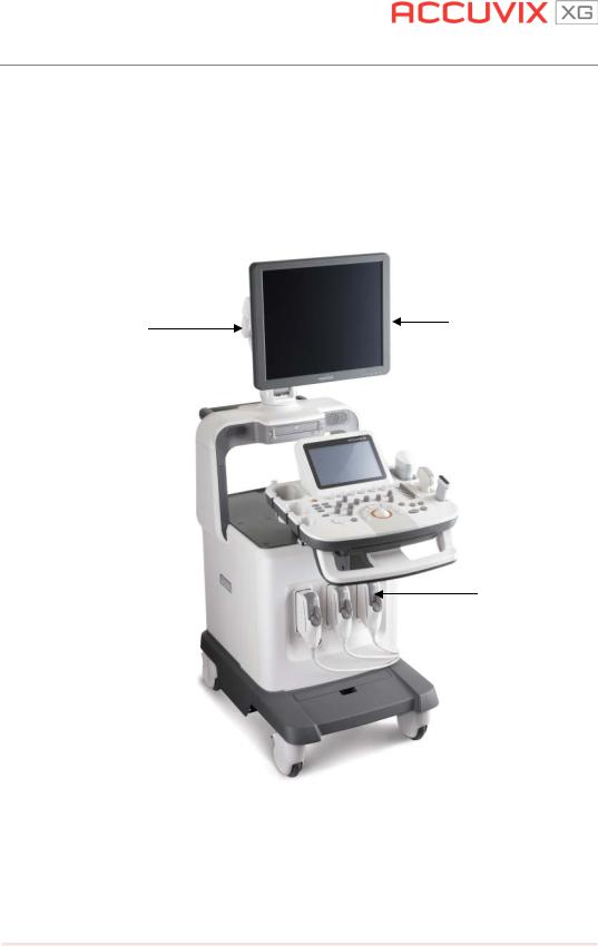
This Product consists of the monitor, the control panel, the console and the probes.
1.3.1 Console
The console consists of two parts – the inner unit and the outer unit. The interior of the console mainly contains devices that produce ultrasound images. On the exterior of the console are various connectors, probe holders, storage compartments, handles, wheels, etc.
LCD
LCD ARM
 Control Panel
Probe Connectors
 Caster
[Figure 1-1] Console ofACCUVIX XG
Chapter 1. General Information 1-3
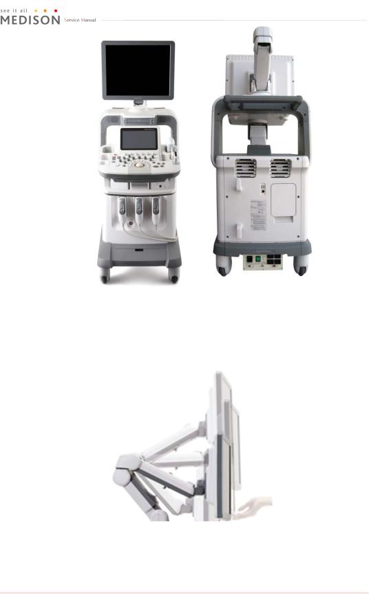
[Figure 1-2] Rear and side ofACCUVIX XG
1.3.2 LCD Monitor
The monitor of this system is a color VGA monitor, which displays ultrasound images and additional information. Use the monitor arm to adjust the height or position of the monitor.
[Figure 1-3] LCDArm
Chapter 1. General Information 1-4

1.3.3 Control Panel
The control panel can be used for controlling the system. It consists of the following four sections:
1)Function keys for mode selection and scanning, located on the top side of the control panel.
2)Function keys for annotation and measurements, located around the Trackball.
3)Menu selection buttons, located on the left side of the control panel.
4)An alpha-numeric keyboard, located under the control panel.
Dial Button 
Button
Slide Volume
Track Ball
[Figure 1-4] Control Panel
1.3.4 Probe
Probes are devices that generate ultrasound waves and process reflected wave data for the purpose of image formation.
NOTE˙ ˙ ˙ ˙
For more information, refer to `Chapter 9 Probes’.
Chapter 1. General Information 1-5
1.4 Specifications
|
|
|
|
Height: 1340 ~ 1600mm (monitor) / 808 ~ 988mm(CP Trackball) |
|
|
|
Physical Dimensions |
|
|
Width: 540mm |
|
|
|
|
|
Depth: 885 ~ 975mm |
|
||
|
|
|
|
|
||
|
|
|
|
Weight: 106.6kg, 235.3lb (with monitor) |
|
|
|
|
|
|
|
|
|
|
|
|
2D mode |
|||
|
|
|
M-Mode |
|||
|
|
|
Color Doppler |
|||
|
|
|
Pulsed Wave (PW) Spectral Doppler |
|||
Imaging modes |
Continuous Wave (CW) Doppler |
|||||
Tissue Doppler Imaging (TDI) |
||||||
|
|
|
||||
|
|
|
Power Doppler (PD) |
|||
|
|
|
Directional Power Doppler (DPD) |
|||
|
|
|
Color M-Mode |
|||
|
|
|
Anatomical M |
|||
|
|
|||||
|
Gray Scale |
|
|
256 (8 bits) |
|
|
|
|
|
|
|
|
|
|
|
|
Transmit focusing, maximum of eight points |
|||
Focusing |
|
(four points simultaneously selectable) |
||||
|
|
|
Digital dynamic receive focusing (continuous) |
|||
|
|
|
|
|||
|
|
|
|
Phased Array |
|
|
|
|
|
|
P2-4BA, P3-8CA, P4-12 |
|
|
|
|
|
|
Linear Array |
|
|
|
|
|
|
L3-8, L5-13IS, LF5-12, LS5-13 |
|
|
|
Probes |
|
|
Curved Array |
|
|
|
|
|
C1-4EC, C2-6IC, C4-9/10ED, VR5-9, EV4-9/10ED, ER4-9/10ED |
|
||
|
|
|
|
|
||
|
|
|
|
3D |
|
|
|
|
|
|
V4-8, 3DC2-6, V5-9, V6-12 |
|
|
|
|
|
|
CW |
|
|
|
|
|
|
CW 2.0, CW 4.0 |
|
|
|
|
|
|
|
|
|
Probe connections |
4 probe Probe Ports (including Pencil probe) |
|||||
|
|
|||||
|
Monitor |
|
|
19 inch LCD monitor |
|
|
|
|
|
|
|
|
|
Chapter 1. General Information 1-6

|
VHS and SVHS VCR left and right audio |
|
|
B/W printer video and remote control |
|
Rear Panel |
VGA monitor |
|
Serial Communication |
||
Input/Output |
||
Parallel Communication |
||
Connections |
||
Microphone |
||
|
||
|
LAN |
|
|
USB |
|
|
|
|
|
Maximum 5400 frames for CINE memory |
|
Image Storage |
Maximum 8192 Lines for LOOP memory |
|
|
Image filing system |
|
|
|
|
|
Obstetrics, Gynecology, Urology, Abdomen, Cardiac, Vascular, |
|
Application |
Small Part, Muskuloskeletal, Contrast, Pediatric, Intraoperative, |
|
|
TCD |
|
|
|
|
Electrical Parameters |
100-120 / 200-240VAC, 950VA, 50/60Hz |
|
|
|
|
|
Abdomen, Cardiac, Fetal Echo, Gynecology, MSK, Pediatric |
|
Measurement Packages |
Hips, Small Part,TCD, Urology, Vascular |
|
|
* Refer the Chapter 5 for additional information |
|
|
|
|
|
TGC control |
|
|
Mode-independent gain control |
|
|
Acoustic power control (adjustable) |
|
Signal processing |
Dynamic aperture |
|
(Pre-processing) |
Dynamic apodization |
|
|
Dynamic range control (adjustable) |
|
|
Image view area control |
|
|
M-mode sweep speed control |
|
|
|
|
|
Frame average |
|
|
Edge Enhancement / Blurring |
|
Signal processing |
Gamma-scale windowing |
|
(Post-processing) |
Image orientation (left/right and up/down, rotation) |
|
|
White on black/black on white |
|
|
Zoom |
|
|
|
Chapter 1. General Information 1-7

|
Trackball operation of multiple cursors |
|
|
2D mode: Linear measurements and area measurements |
|
Measurement |
using elliptical approximation or trace |
|
|
M mode: Continuous readout of distance, time, and slope rate |
|
|
Doppler mode: Velocity and trace |
|
|
|
|
|
VCR |
|
|
Video Page Printer |
|
|
Color Video Page Printer |
|
|
USB Video Printer |
|
Auxiliary |
USB Color Video Printer |
|
Inkjet Printer |
||
|
||
|
Laser Printer |
|
|
Foot Switch(IPX1) |
|
|
USB Flash Memory Media |
|
|
Monitor |
|
|
|
|
User Interface |
English, German, French, Spanish, Italian, Russian, Chinese |
|
|
|
|
Pressure Limits |
Operating: 700hPa to 1060hPa |
|
Storage: 700hPa to 1060hPa |
||
|
||
|
|
|
|
Operating: 30% to 80% |
|
Humidity Limits |
Storage & Shipping: 30% to 90% |
|
|
Transport: 30% to 90% |
|
|
|
|
|
Operating: 10 OC ~ 40OC |
|
Temperature Limits |
Storage & Shipping: -10OC ~ 50OC |
|
|
Transport: -20 ~ 60 OC |
|
|
|
Chapter 1. General Information 1-8

Chapter 2. Safety
2.1 Overview
Chapter 2 contains the information necessaryto Safety
Please read this chapter before using the MEDISON ultrasound system. It is relevant to the ultrasound system, the probes, the recording devices, and any of the optional equipment.
ACCUVIX XG is intended for use by, or by the order of, and under the supervision of, a licensed physician who is qualified for direct use of the medical device.
Contents
2.1 |
Overview |
.................................................................................................... |
2-1 |
2.2 |
Safety – Related Information ..................................................................... |
2-2 |
|
|
2.2.1 |
Safety Symbols......................................................................... |
2-2 |
|
2.2.2 |
Label .......................................................................................... |
2-4 |
2.3 |
Electrical Safety........................................................................................... |
2-7 |
|
|
2.3.1 |
Prevention Electric Shock ....................................................... |
2-7 |
|
2.3.2 |
ECG - Related Information...................................................... |
2-8 |
|
2.3.3 |
ESD............................................................................................ |
2-8 |
|
2.3.4 |
EMI............................................................................................. |
2-9 |
|
2.3.5 |
EMC........................................................................................... |
2-9 |
2.4 |
Mechanical Safety..................................................................................... |
2-15 |
|
|
2.4.1 |
Moving Equipment ................................................................. |
2-15 |
|
2.4.2 |
Safety Note ............................................................................. |
2-16 |
2.5 |
Biological Safety........................................................................................ |
2-18 |
|
|
2.5.1 |
ALARA Principle..................................................................... |
2-18 |
2.6 |
Environmental Protection......................................................................... |
2-30 |
|
Chapter 2. Safety |
2-1 |

2.2Safety - Related Information
2.2.1Safety Symbols
The International Electro Technical Commission (IEC) has established a set of symbols for medical electronic equipment, which classifies a connection or warn of potential hazards. The classifications and symbols are shown below.
Stmbols |
Description |
|
|
AC (alternating current) voltage source
Isolated patient connection (Type BF applied part)
Power switch (Supplies/cuts the power for product)
Indicates a caution for risk of electric shock
Indicates dangerous voltages over 1000VAC or over 1500V DC
CAUTION
Identifies an equipotential ground
Identifies the point where the system safetyground is fastened to the chassis. Protective earth connected to conductive parts of Class I equipment for safety purposes
ESD (Electrostatic discharge) caution symbol
Data Output port
Data Input port
Data Input/Output port
Chapter 2. Safety |
2-2 |

|
|
|
|
|
Left and rightAudio / Video input |
|
|
|
Left and rightAudio / Video output |
|
|
|
Print remote output |
|
|
|
Foot switch connector |
|
|
|
ECG connector |
|
|
|
USB connector |
|
|
|
Microphone connector |
|
|
|
Protection against the effects of immersion |
|
|
|
Protection against dripping water |
|
|
|
Probe connector |
|
|
|
Do not sit on control panel |
|
|
|
Do not push the product |
|
|
|
Do not lean against the product |
|
|
|
Follow the operation manual |
|
|
Chapter 2. Safety |
2-3 |
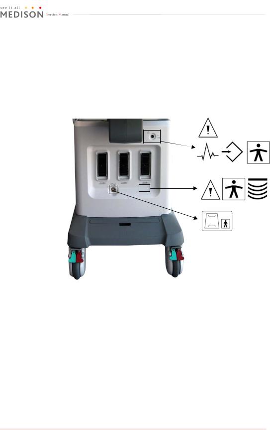
2.2.2Labels
To protect the system, you may see ‘Warning’ or ‘Caution’ marked on the surface of the product
1) Front
[Figure 2-1] Labels of Front
Chapter 2. Safety |
2-4 |

2) Rear
[Figure 2-2] Labels of Rear
3) Monitor
[Figure 2-3] Labels of Monitor
Chapter 2. Safety |
2-5 |
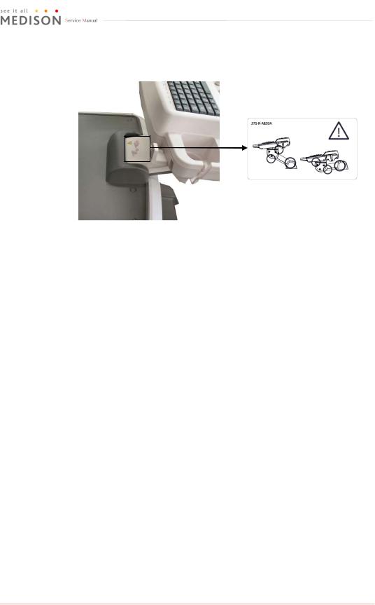
4) Control Panel Lift
[Figure 2-4] Control Panel Lift
Chapter 2. Safety |
2-6 |

2.3 Electrical Safety
This equipment has been verified as a Class I device with Type BF applied parts.
 CAUTION˙ ˙ ˙ ˙ ˙ ˙ ˙
As for US requirement, the LEAKAGE CURRENT might be measured from a centertapped circuit when the equipment connects in the United States to 240V supply system.
To help assure grounding reliability, connect to a “hospital grade” or “hospital only” grounded power outlet.
2.3.1Prevention of Electric Shock
In a hospital, dangerous currents are due to the potential differences between connected equipment and touchable conducting parts found in medical rooms. The solution to the problem is consistent equipotential bonding. Medical equipment is connected with connecting leads made up of angled sockets to the equipotential bonding network in medical rooms.
[Figure 2-6] Equipotential bonding
Additional equipment connected to medical electrical equipment must comply with the respective IEC or ISO standards (e.g. IEC 60950 for data processing equipment). Furthermore all configurations shall comply with the requirements for medical electrical systems (see IEC 60601-1-1 or clause 16 of the 3 Ed. of IEC 60601-1, respectively). Anybody connecting additional equipment to medical electrical equipment configures a medical system and is therefore responsible that the system complies with the requirements for medical electrical systems. Attention is drawn to the fact that local laws take priority over the above-mentioned requirements. If in doubt, consult your local representative or the technical service department.
Chapter 2. Safety |
2-7 |
 Loading...