


AC160JXAFKH
Samsung AC160JXAFKH, AC180JNHFKH, AC160JXAFNH, AC180JXAFNH, AC200JNHFKH Service Manual
...
AIR CONDITIONER CONTENTS
SYSTEM AIR CONDITIONER
1. Precautions
2. Product Speci cations
3. Disassembly and Reassembly
4. Troubleshooting
5. PCB Diagram
6. Wiring Diagram
7. Reference Sheet
AC160JNHFKH
AC180JNHFKH
AC200JNHFKH
AC180JNHPKH
AC200JNHPKH
Indoor Unit Outdoor Unit
Model Name
:
AC160JNHFKH AC160JXAFKH
AC160JNHFKH AC160JXAFNH
AC180JNHFKH AC180JXAFNH
AC200JNHFKH AC200JXAFNH
AC180JNHPKH AC180JXAPNH
AC200JNHPKH AC200JXAPNH
Model Code
:
AC160JNHFKH/SA AC160JXAFKH/SA
AC160JNHFKH/SA AC160JXAFNH/SA
AC180JNHFKH/SA AC180JXAFNH/SA
AC200JNHFKH/SA AC200JXAFNH/SA
AC180JNHPKH/EU AC180JXAPNH/EU
AC200JNHPKH/EU AC200JXAPNH/EU
AC160JXAFKH
AC160JXAFNH
AC180JXAFNH
AC180JXAPNH
AC200JXAFNH
AC200JXAPNH

Contents
11. Precautions
..........................................................................................................................................
1-1
1-1 Precautions for the Service
.............................................................................................................
1-1
1-2 Precautions for the Static Electricity and PL
................................................................................
1-1
1-3 Precautions for the Safety
...............................................................................................................
1-1
1-4 Others
..................................................................................................................................................
1-1
12. Product Specifications
..................................................................................................................
2-1
2-1 The Feature of Product
....................................................................................................................
2-1
2-2 Product Specifications
.....................................................................................................................
2-2
2-3 Accessory
...........................................................................................................................................
2-8
3. Disassembly and Reassembly
...................................................................................................
3-1
3-1 Indoor Unit
.........................................................................................................................................
3-2
3-2 Outdoor Unit
.....................................................................................................................................
3-14
4. Trouble shooting
..............................................................................................................................
4-1
4-1 Indoor Display Error and Check Method
.....................................................................................
4-1
4-1-1 Indoor unit LED lamp display at error detecting
.............................................................
4-1
4-2 Outdoor Trouble shooting
.............................................................................................................
4-4
4-3 Troubleshooting by symptoms
......................................................................................................
4-6
4-3-1 Indoor temperature sensor (open/short) .................................................................................... 4-6
4-3-2 Eva in and out sensor (open/short) ............................................................................................... 4-7
4-3-3 Float switch(Open) ................................................................................................................................ 4-8
4-3-4 Fan error .................................................................................................................................................... 4-9
4-3-5 EEPROM error .......................................................................................................................................... 4-10
4-3-6 Option error ............................................................................................................................................. 4-11
4-3-7 Terminal Block's Terminal Fuse(Open) .......................................................................................... 4-12
4-3-8 Communication error after finishing tracking (E202) ............................................................ 4-13
4-3-9 Outdoor's service valve(Clog) .......................................................................................................... 4-14
4-3-10 No Power(completely dead) - Initial diagnosis ...................................................................... 4-15
4-3-11 E102 : Communication error between indoor and outdoor unit
E201 : Unit quantity miss matching beween Indoor and Outdoor
E202 : Abnormal state, no communication between Indoor and Outdoor Main PCB
E203 : 1min Time out of communication error(MainInverter) ...................................... 4-19
4-3-12 External Sensor Error (Error Code: E221, E231, E251, E320) .............................................. 4-20
4-3-13 E403 : Freezing control causes comp. down ........................................................................... 4-21
4-3-14 E416 : Dischage temperature sensor error ............................................................................... 4-22
4-3-15 E440, E441 : Abnormal outside temperature halts operation of the compressor ... 4-23
4-3-16 Outdoor unit BLDC Fan1 or Fan2 error (E458 : Fan1 error, E475 : Fan2 error) ........... 4-24
4-3-17 E461: Compressor start error
E467: Compressor wire missing error ........................................................................................ 4-25
4-3-18 E462 : Current protection control causes comp. down
E484 : PFC overload errorr .............................................................................................................. 4-26
4-3-19 E463 : OLP protection control caused comp. down ............................................................. 4-27
4-3-20 E464 : O.C. (Over Current) error ..................................................................................................... 4-28
4-3-21 E466: DC Link Over voltage/ Low voltage error ..................................................................... 4-29
4-3-22 Pipe Blocking Error (Error Code: E422) ....................................................................................... 4-30

Samsung Electronics
3
Contents
4-3-23 The others .............................................................................................................................................. 4-31
4-4 Setting Option Setup Method ...................................................................................................................... 4-32
4-5 Items to be checked first ................................................................................................................................ 4-38
5. PCB Diagram and Parts list
..........................................................................................................
5-1
5-1 INDOOR UNIT ..................................................................................................................... 5-1
5-2 OUTDOOR UNIT ................................................................................................................ 5-4
6. Wiring Diagram
.................................................................................................................................
6-1
6-1 Indoor Unit ............................................................................................................................................................ 6-1
6-2 Outdoor Unit ........................................................................................................................................................ 6-2
7. Reference Sheet
...............................................................................................................................
7-1
7-1 Refrigerating Cycle Diagram
..........................................................................................................
7-1
7-2 Index for Model Name
.....................................................................................................................
7-2

1-1
Samsung Electronics
1. Precautions
1-1 Precautions for the Service
Use the standard parts when replacing the electric parts.
– Confirm the model name, rated voltage, rated current of the electric parts.
Repair the disconnection of HARNESS securely when repairing the break down.
– If there is any connection error, it causes an abnormal noise and incorrect operation.
In case that you assemble or disassemble the products with laying it on the side, do work on the work cloth.
– If not, the exterior of products can be scratched.
Remove dust and foreign materials from harness, connection part, and inspection part thoroughly when repairing the break down.
– It protects the danger of fire such as tracking and short.
Tighten tightly the service valve of outdoor unit and the cap of charging valve with a monkey spanner.
Check the assembly status of parts after repairing the break down.
– It should be same as the status before repairing.
1-2 Precautions for the Static Electricity and PL
As the PCB power terminal has a weakness for the static electricity, pay attention to it during the repair and measurement.
– Work with insulation gloves during the repair and measurement of PCB.
Check the distance between the product and the other electronic appliances such as TV, video, and audio. It should be over 2m.
– If not, it causes a bad picture quality or a noise.
Repairing the products by consumer should be strictly prohibited.
– There is a danger of electric shock or fire due to incorrect disassembly.
1-3 Precautions for the Safety
Do not pull any electric wires and do not touch an auxiliary power switch with a wet hand.
– There is a danger of electric shock or fire.
In case any wire or power plug has been damaged, replace it to eliminate any possible danger.
Do not bend the power cord by force and do not put any heavy object on the power cord.
– There is a danger of electric shock or fire.
Do not use multi socket.
– There is a danger of electric shock or fire.
Ground the product if necessary.
– Be sure to ground the product if there is any danger of electric leakage due to water or moisture.
Be sure to turn off the auxiliary power switch or pull out the power plug during replacement or repair of electric parts.
– There is a danger of electric shock.
In case the product will not be in use for a long time, the battery of remote control should be kept separately.
– Leakage of inside fluid can cause break down of remote control.
1-4 Others
Never store or load the air conditioner upside down or sideways to prevent the damage to the compressor.
Young children or infirm persons should be always supervised when they use the air conditioner.
Max current is measured according to IEC standard for safety.
Current is measured according to ISO standard for energy efficiency.
When installing, make sure there is no leakage. When recovering the refrigerant, ground the compressor first before removing the connec-
tion pipe. If the refrigerant pipe is not properly connected and the compressor works with the service valve open, the pipe inhales the air
and it makes the pressure inside of the refrigerant cycle abnormally high. It may cause explosion and injury.
P
ump Down Procedure (When removing the product)
- Turn on the air conditioner and select Cool mode to run the compressor for 3 minutes.
- Release the valve caps on High and Low pressure side.
- Use L wrench to close the valve on the high pressure side.
- Approximately 2 minutes after, close the valve on the low pressure side.
- Stop operation of the air conditioner.
- Disconnect the pipes.

Samsung Electronics
2-1
2. Product Specifications
2-1 The Feature of Product
■ Built-in Duct Type
After installed, the air conditioner can be harmonized with a room interior.
■ High Performance & Energy Saving
With the advanced BLDC inverter technology, it makes a room cool with highly energy saving and arises the efficiency of air
conditioner.
■ Long Piping (Length & Height)
It can give the benefit to the installers and aries the reliability of the air conditioner.
■ Long Ambient Operation (In Low Temperature)
It can arise the reliability and the capacity of the air conditioner, especially operated in low temperature.
■ Eco-friendly Product (Lead-Free, RoHS, WEEE)
2-2
Samsung Electronics
ITEM
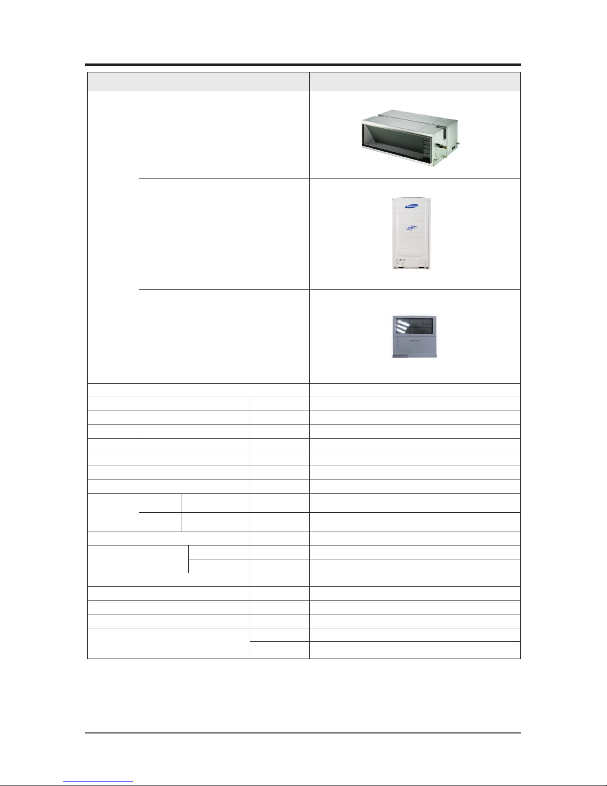
AC200JNHFKH
AC200JXAFNH
IMAGE
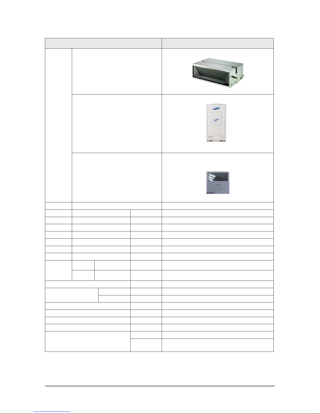
Indoor Unit
Outdoor Unit
Remote Controller
MWR-WE10N
Power Product
3Φ, 380~415V/50Hz
Indoor W*D*H mm
1350 x 910 x 450
Outdoor W*D*H mm
880 x 765 x 1695
Indoor Product kg(Net)
82.5
Outdoor Product kg(Net)
190
Capacity Cooling/Heating(ISO) W
20000/22500
Power input Cooling/Heating (ISO) W
6060/6080
Operation current Cooling/Heating (ISO) A
9.8/9.9
Noise
(Cooling/Heating)
Indoor unit
In case of strongest air
blow
dB
52/52
Outdoor unit
In case of strongest air
blow
dB
68/68
Refrigerant (R410A) g
8000 (Charged for 30m)
Connecting Pipe
Liquid mm
9.52
Gas mm
19.05
Additional Refrigerant (R410A) g/m
60
Standard m
7.5
Extension length(Total) m
150
Extension length(Elevation) m
50
Option Code
Product Option
012474-1C50C0-20C8E1-320000
Installation Option
020000-100000-200000-300000
030000-100000-200000-300000
2-2 Product Spectification
Samsung Electronics
2-3
ITEM
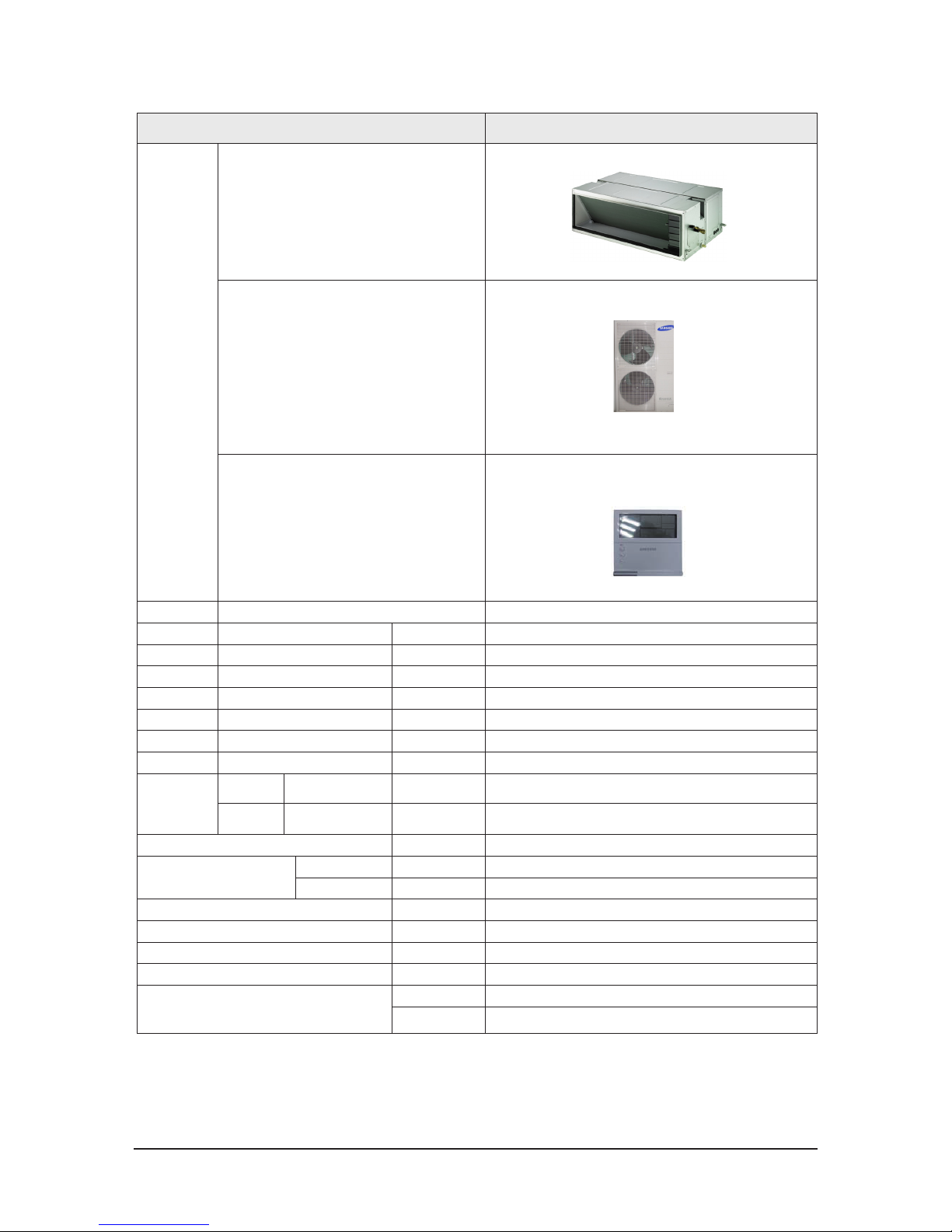
AC180JNHFKH
AC180JXAFNH
IMAGE
Indoor Unit
Outdoor Unit
Remote Controller
MWR-WE10N
Power Product
3Φ, 380~415V/50Hz
Indoor W*D*H mm
1350 x 910 x 450
Outdoor W*D*H mm
940 x 330 x 1420
Indoor Product kg(Net)
82.5
Outdoor Product kg(Net)
97
Capacity Cooling/Heating(ISO) W
18000/20000
Power input Cooling/Heating (ISO) W
5290/5410
Operation current Cooling/Heating (ISO) A
8.1/8.4
Noise
(Cooling/Heating)
Indoor unit
In case of strongest air
blow
dB
51/51
Outdoor unit
In case of strongest air
blow
dB
63/65
Refrigerant (R410A) g
4600 (Charged for 30m)
Connecting Pipe
Liquid mm
9.52
Gas mm
19.05
Additional Refrigerant (R410A) g/m
50
Standard m
5
Extension length(Total) m
75
Extension length(Elevation) m
30
Option Code
Product Option
01107C-1C50B0-27B414-370060
Installation Option
020000-100000-200000-300000
030000-100000-2463E3-3B4402
2-4
Samsung Electronics
ITEM
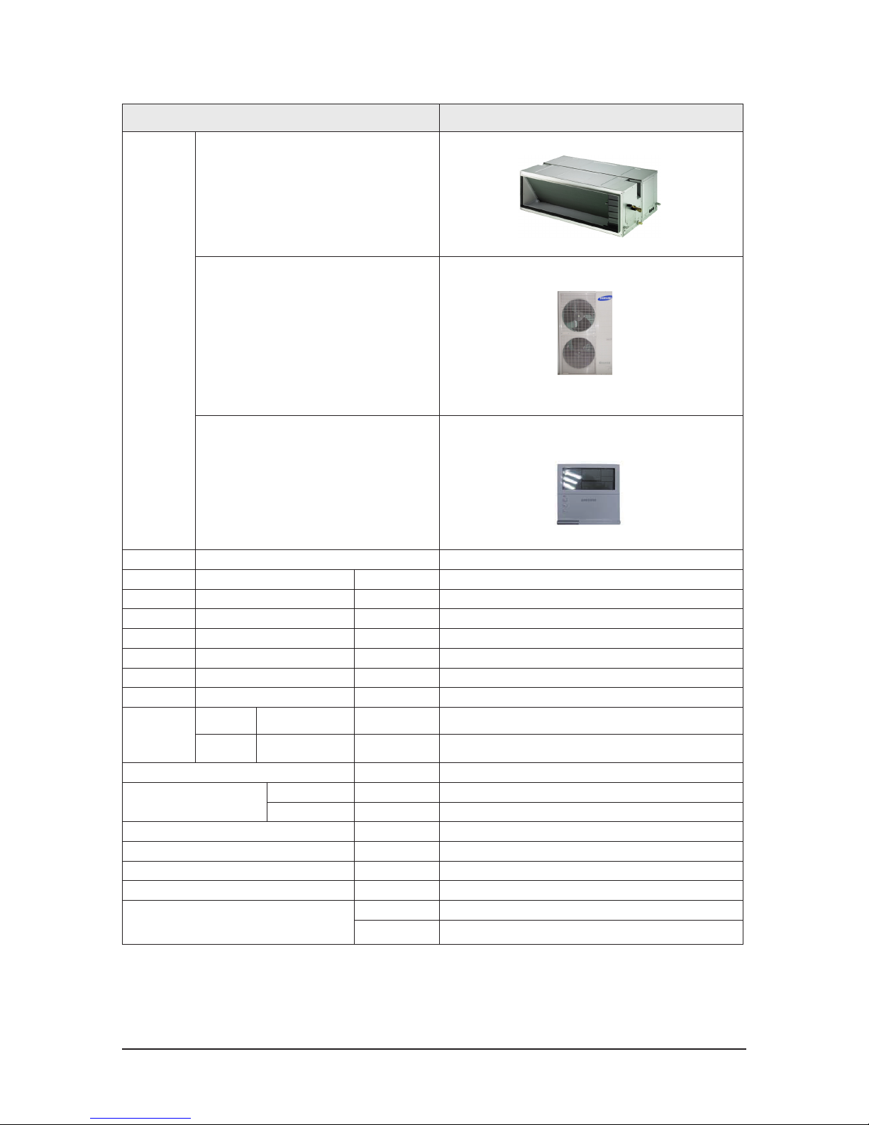
AC160JNHFKH
AC160JXAFNH
IMAGE
Indoor Unit
Outdoor Unit
Remote Controller
MWR-WE10N
Power Product
3Φ, 380~415V/50Hz
Indoor W*D*H mm
1350 x 910 x 450
Outdoor W*D*H mm
940 x 330 x 1420
Indoor Product kg(Net)
78.5
Outdoor Product kg(Net)
95
Capacity Cooling/Heating(ISO) W
16000/18000
Power input Cooling/Heating (ISO) W
4710/4860
Operation current Cooling/Heating (ISO) A
7.4/7.6
Noise
(Cooling/Heating)
Indoor unit
In case of strongest air
blow
dB
50/50
Outdoor unit
In case of strongest air
blow
dB
62/64
Refrigerant (R410A) g
3500 (Charged for 30m)
Connecting Pipe
Liquid mm
9.52
Gas mm
15.88
Additional Refrigerant (R410A) g/m
50
Standard m
5
Extension length(Total) m
75
Extension length(Elevation) m
30
Option Code
Product Option
01107C-1C50A0-27A0B4-370060
Installation Option
020000-100000-200000-300000
034338-103D48-243383-3D4802

Samsung Electronics
2-5
ITEM
AC160JNHFKH
AC160JXAFKH
IMAGE
Indoor Unit
Outdoor Unit
Remote Controller
MWR-WE10N
Power Product
1Φ, 220~240V/50Hz
Indoor W*D*H mm
1350 x 910 x 450
Outdoor W*D*H mm
940 x 330 x 1420
Indoor Product kg(Net)
78.5
Outdoor Product kg(Net)
95
Capacity Cooling/Heating(ISO) W
16000/18000
Power input Cooling/Heating (ISO) W
4710/5860
Operation current Cooling/Heating (ISO) A
21/21
Noise
(Cooling/Heating)
Indoor unit
In case of strongest air
blow
dB
50/50
Outdoor unit
In case of strongest air
blow
dB
62/64
Refrigerant (R410A) g
3500 (Charged for 30m)
Connecting Pipe
Liquid mm
9.52
Gas mm
15.88
Additional Refrigerant (R410A) g/m
50
Standard m
5
Extension length(Total) m
75
Extension length(Elevation) m
30
Option Code
Product Option
01107C-1C50A0-27A0B4-370060
Installation Option
020000-100000-200000-300000
034338-103D48-243383-3D4802

2-6
Samsung Electronics
ITEM
AC180JNHPKH
AC180JXAPNH
IMAGE
Indoor Unit
Outdoor Unit
Remote Controller
MWR-WE10N
Power Product
3Φ, 380~415V/50Hz
Indoor W*D*H mm
1350 x 910 x 450
Outdoor W*D*H mm
940 x 330 x 1420
Indoor Product kg(Net)
82.5
Outdoor Product kg(Net)
107.5
Capacity Cooling/Heating(ISO) W
18000/20000
Power input Cooling/Heating (ISO) W
5450/5540
Operation current Cooling/Heating (ISO) A
8.4/8.6
Noise
(Cooling/Heating)
Indoor unit
In case of strongest air
blow
dB
51/51
Outdoor unit
In case of strongest air
blow
dB
63/65
Refrigerant (R410A) g
4600 (Charged for 30m)
Connecting Pipe
Liquid mm
9.52
Gas mm
19.05
Additional Refrigerant (R410A) g/m
50
Standard m
5
Extension length(Total) m
75
Extension length(Elevation) m
30
Option Code
Product Option
01107C-1C50B0-27B414-370060
Installation Option
020000-100000-200000-300000
030000-100000-2463E3-3B4402
Samsung Electronics
2-7
ITEM
AC200JNHPKH
AC200JXAPKH
IMAGE
Indoor Unit
Outdoor Unit
Remote Controller
MWR-WE10N
Power Product
3Φ, 380~415V/50Hz
Indoor W*D*H mm
1350 x 910 x 450
Outdoor W*D*H mm
880 x 765 x 1695
Indoor Product kg(Net)
82.5
Outdoor Product kg(Net)
190
Capacity Cooling/Heating(ISO) W
20000/22000
Power input Cooling/Heating (ISO) W
6230/6090
Operation current Cooling/Heating (ISO) A
10.8/10.0
Noise
(Cooling/Heating)
Indoor unit
In case of strongest air
blow
dB
52/52
Outdoor unit
In case of strongest air
blow
dB
68/68
Refrigerant (R410A) g
8000 (Charged for 30m)
Connecting Pipe
Liquid mm
9.52
Gas mm
19.05
Additional Refrigerant (R410A) g/m
60
Standard m
7.5
Extension length(Total) m
150
Extension length(Elevation) m
50
Option Code
Product Option
012474-1C50C0-20C8DC-320000
Installation Option
020000-100000-200000-300000
030000-100000-200000-300000
050000-100000-200000-300000
2-8
Samsung Electronics
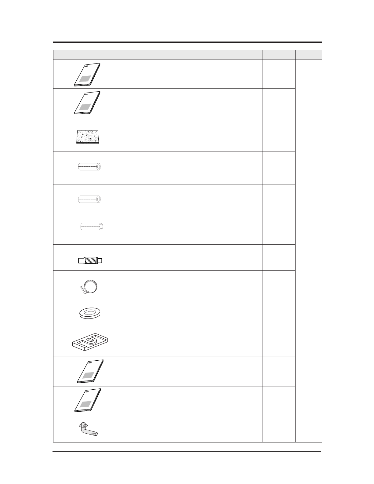
2-3 Accessory
Item
Descriptions Code-No. Q'TY Remark
Owner's Manual
DB98-32657A
1
Indoor
Unit
INSTALLATION MANUAL
DB68-04923A
1
Insulation
DB62-04318S
1
Insu DRAIN HOSE DB62-11028A 1
INSU HOSE D
DB62-11028E
1
INSU TUBE OUT
DB62-11028F
1
ASSY DRAIN HOSE JOINT
DB67-01191A
1
Ass'y Drain Hose Joint
DB90-06701A
1
GROMMET-HANGER
DB63-00237A
8
RUBBER LEG DB73-20134A 4
Outdoor unit
INSTALLATION MANUAL
DB68-04921A
(DVMS)
1
INSTALLATION MANUAL
DB68-04924A
(UB3)
1
DRAIN PLUG
DB67-00477A
1
OWNER'S INSTRUCTIONS
MANUAL DE INSTRUCCIONES
ISTRUZIONI PER L'USO
MANUAL DE INSTRU‚ÍES
MANUEL D'UTILISATION
GEBRAUCHSANWEISUNG
Spl
ut-
type Room Air C
o
nditioner
Aire
a
condicionado
domŽs
tico s
i
stema Spl
it
Condizionatore
d'a
ria per ambienti ad uni
tˆ Sepa
rate
Ap
a
relho
de ar
c
ondi
cionado
tipo
Split
Climatise
u
r de t
yp
e
sŽparŽ
Ge
teilte raumk
l
imaanlage
OWNER'S INSTRUCTIONS
MANUAL DE INSTRUCCIONES
ISTRUZIONI PER L'USO
MANUAL DE INSTRU‚ÍES
MANUEL D'UTILISATION
GEBRAUCHSANWEISUNG
Spl
ut-
type Room Air C
o
nditioner
Aire
a
condicionado
domŽs
tico s
i
stema Spl
it
Condizionatore
d'a
ria per ambienti ad uni
tˆ Sepa
rate
Ap
a
relho
de ar
c
ondi
cionado
tipo
Split
Climatise
u
r de t
yp
e
sŽpar
Ž
Ge
teilte raumk
l
imaanlage
OWNER'S INSTRUCTIONS
MANUAL DE INSTRUCCIONES
ISTRUZIONI PER L'USO
MANUAL DE INSTRU‚ÍES
MANUEL D'UTILISATION
GEBRAUCHSANWEISUNG
Spl
ut-
type Room Air C
o
nditioner
Aire
a
condicionado
domŽs
tico s
i
stema Spl
it
Condizionatore
d'a
ria per ambienti ad uni
tˆ Sepa
rate
Ap
a
relho
de ar
c
ondi
cionado
tipo
Split
Climatise
u
r de t
yp
e
sŽparŽ
Ge
teilte raumk
l
imaanlage
Samsung Electronics
3-1
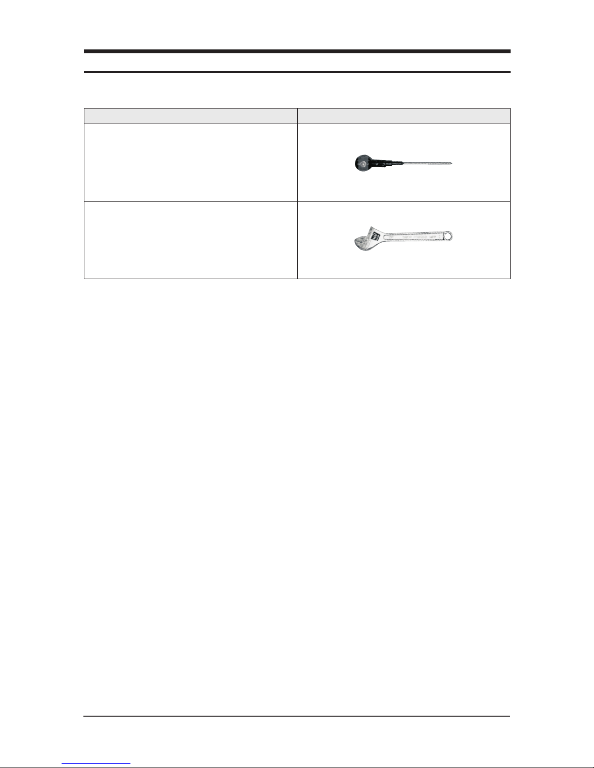
3. Disassembly and Reassembly
■ Necessary Tools
Item Remark
+SCREW DRIVER
MONKEY SPANNER
3-2
Samsung Electronics
3-1 Indoor Unit
■ AC160JNHFKH/AC180JNHFKH/AC200JNHFKH/AC180JNHPKH/AC200JNHPKH
No Parts Procedure Remark
1 Commom 1)Disasseble the Cover Control.
- Unscrew 2 screws

Samsung Electronics
3-3
No Parts Procedure Remark
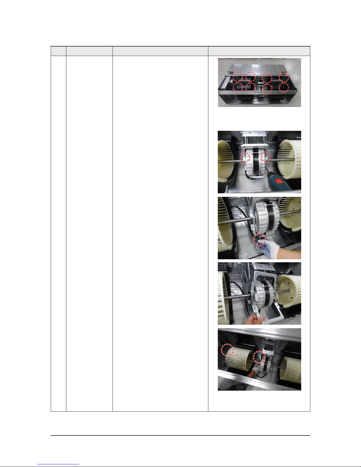
2 Motor & Fan 1) Disassemble the connection wire to take
the motor fan out
2) Disassemble th Cabinet Top Fan.
- Unscrew 6 screws
3) Disassemble the Link Screw
- Unscrew 3 screws
4) Disassemble Cabinet Top Fan.
➤ service from Top side
3-4
Samsung Electronics
No Parts Procedure Remark
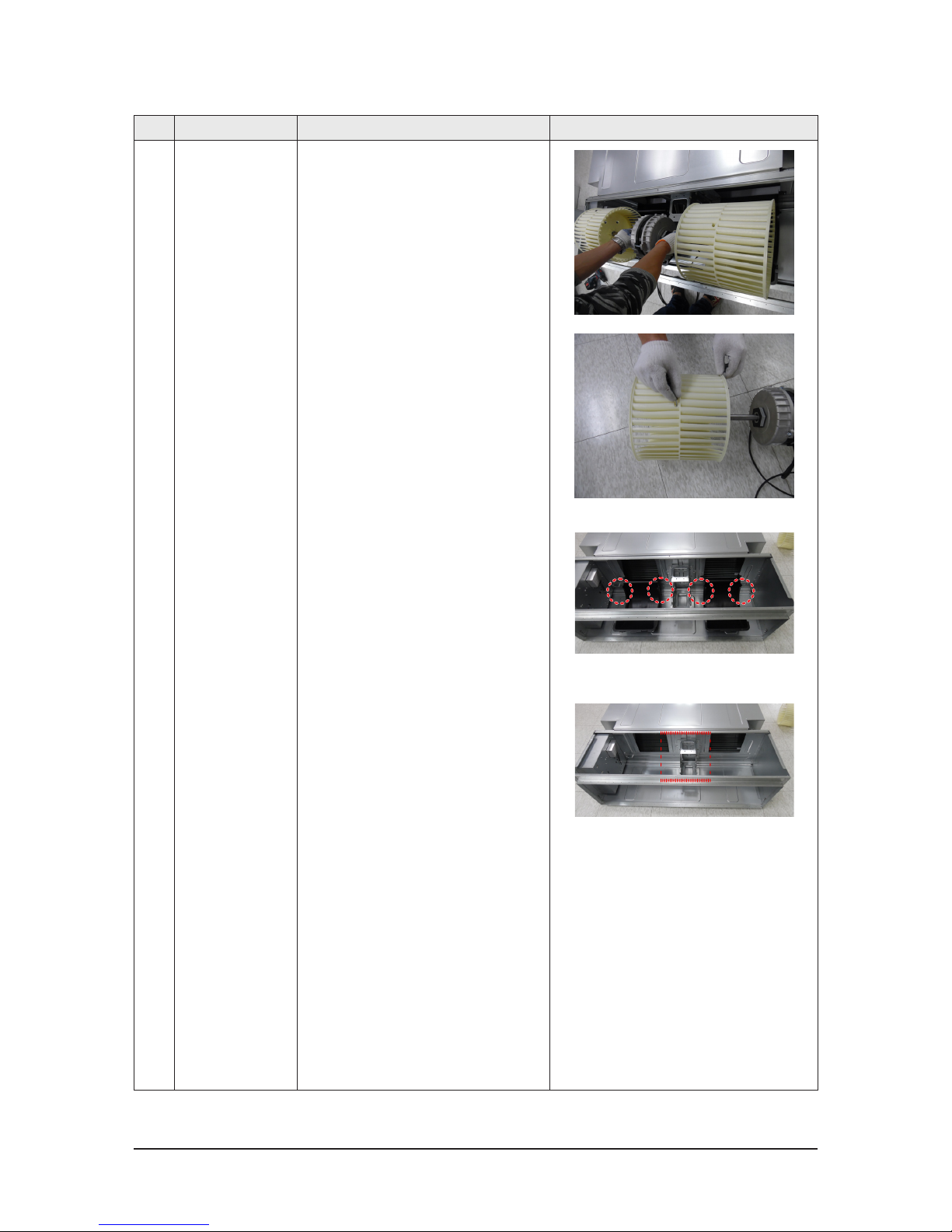
5) Disassemble 2 Case Blower Top.
- Unscrew 8 screws
6) Disassemble 1 Holder Motor.
- Unscrew 2 screws
7)Disassemble Motor wire from 2 holder wire
Samsung Electronics
3-5
No Parts Procedure Remark
8) After disassemble the Motor and Blower for
the set, disassemble the Blower by use of 3mm
wrench.
9)Disassemble 2 Case blower bottom.
- Unscrew 4 screws
10)Disassemble the Bracket Motor.
- Unscrew 4 screws
3-6
Samsung Electronics
No Parts Procedure Remark
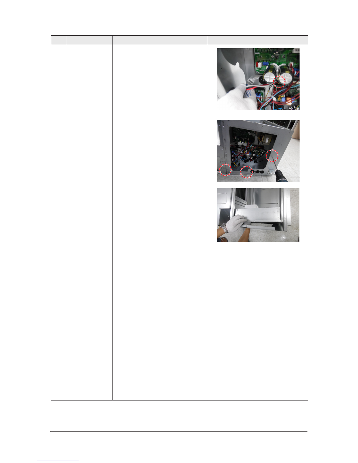
3 Control Box 1)Disassemble Evap Sensor wire and EEV
wire(20kW only)
2) Disassemble the Case Control.
- Unscrew 3 screws
Samsung Electronics
3-7
No Parts Procedure Remark
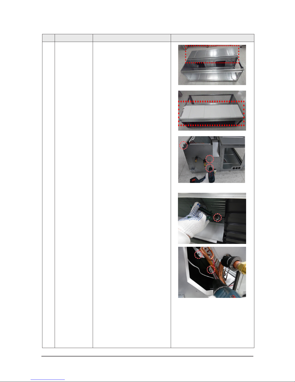
4 Evap 1)Disassemble The Case Evap Top
- [AC***JNHFKH]Unscrew 8 screws
- [AC***JNHPKH]Unscrew 6 screws
2)Disassemble The Cushion Front.
3)Disassemble The Cushion Support.
- Unscrew 1 screw
3-8
Samsung Electronics
No Parts Procedure Remark
4)Disassemble The Cover pipe.
- Unscrew 3 screws
5)Remove The cable tie on the Support Evap
6)Disassemble The Evap.
- Unscrew 4 screws
Samsung Electronics
3-9
No Parts Procedure Remark
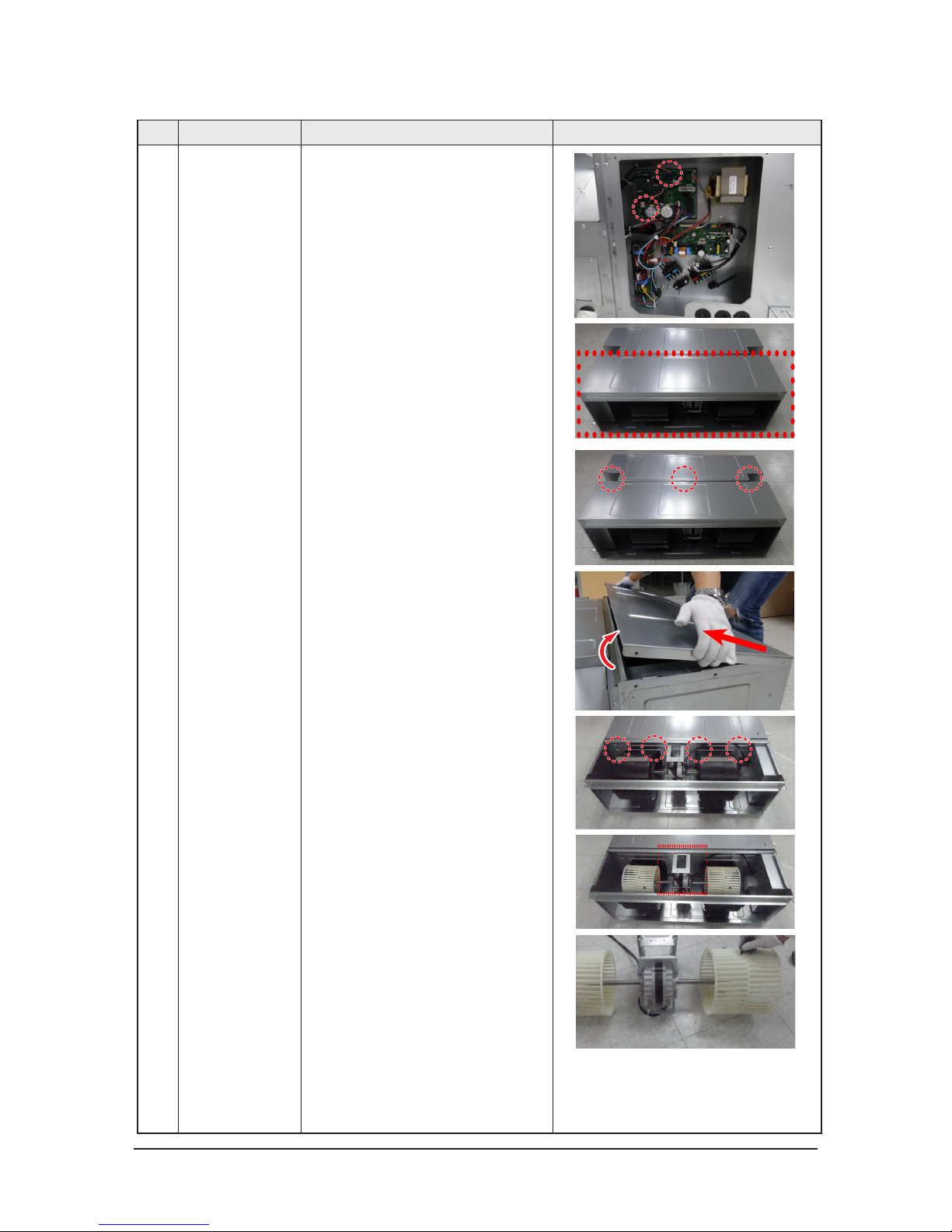
1 Motor & Fan 1)Disassembl the connection wire to take the
motor fan out
2) Diassemble The Cabi Fan Bottom.
- Unscrew 9 screws
3) Disassemble the Link Screw
- Unscrew 3 screws
4)Disassemble 2 Case blower bottom.
- Unscrew 4 screws
5)Disassemble Bracket Motor and Motor.
- Unscrew 4 screws
6)After disassemble the Motor and Blower for
the set, disassemble the Blower by use of 3mm
wrench.
➤ service from Bottom side

3-10
Samsung Electronics
No Parts Procedure Remark
7)Disassemble The Case Blower Top.
- Unscrew 8 screws
Samsung Electronics
3-11
No Parts Procedure Remark
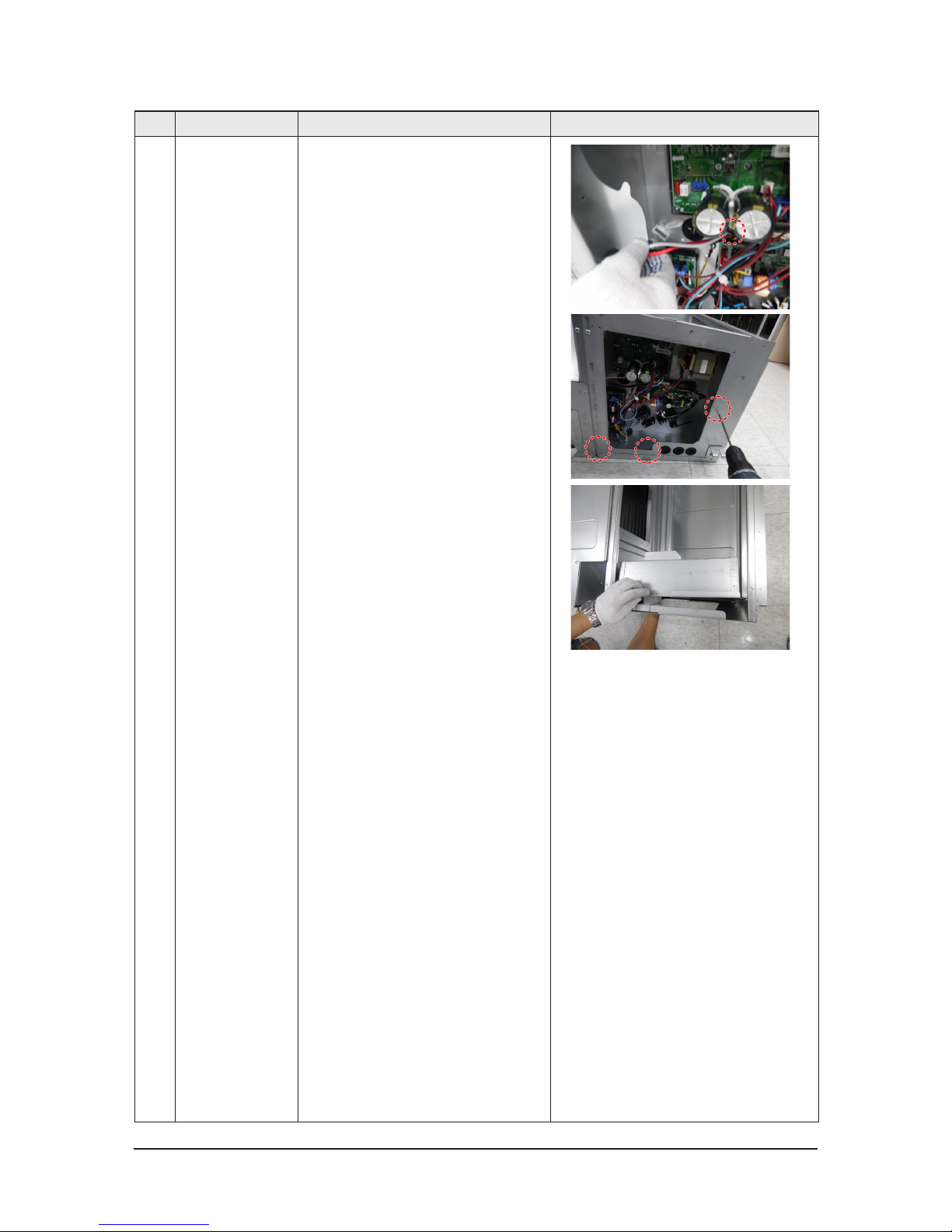
2 Control Box 1)Disassemble Evap Sensor wire and EEV
wire(20kW only)
2) Disassemble the Case Control.
- Unscrew 3 screws
3-12
Samsung Electronics
No Parts Procedure Remark
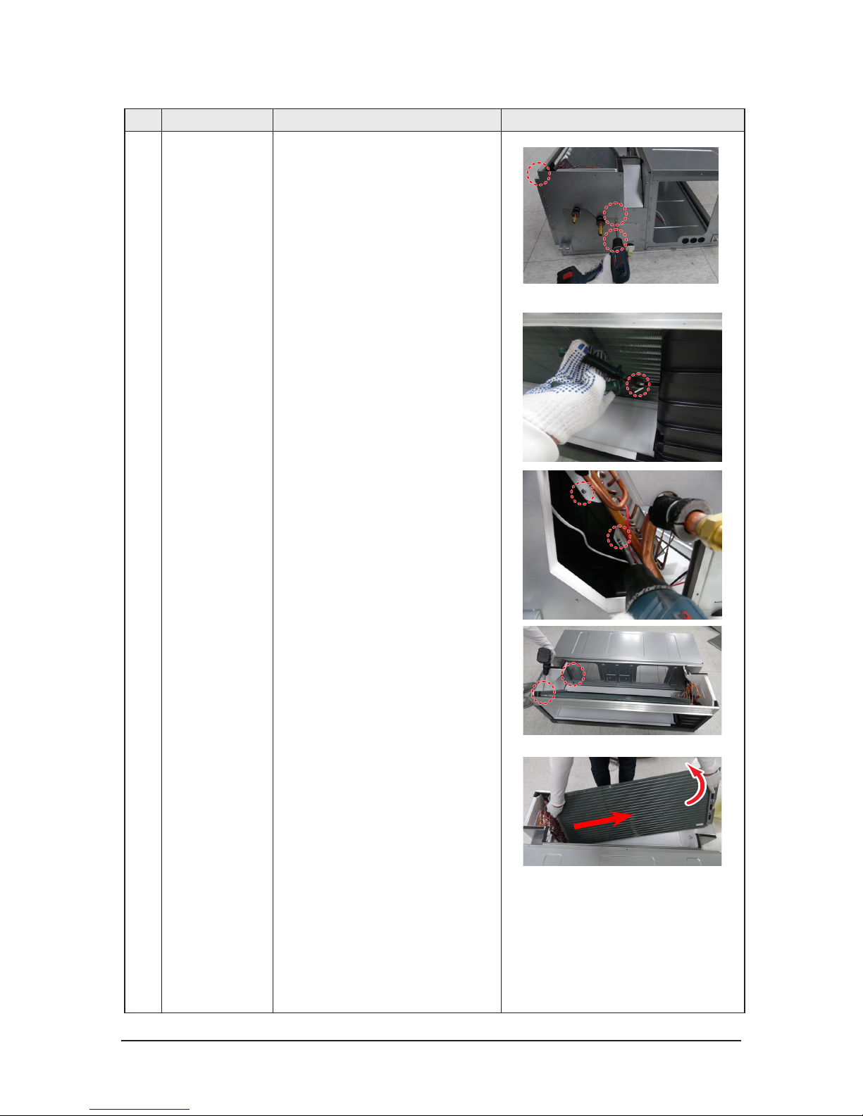
3 Evap 1)Disassemble The Case Evap Bottom
- [AC***JNHFKH]Unscrew 11 screws
- [AC***JNHPKH]Unscrew 7 screws
2)Disassemble The Drain Pan
3)Disassemble The Cover pipe.
- Unscrew 3 screws
4)Remove The cable tie on the Support Evap
5)Disassemble The Support Evap.
- Unscrew 2 screws
Samsung Electronics
3-13
No Parts Procedure Remark
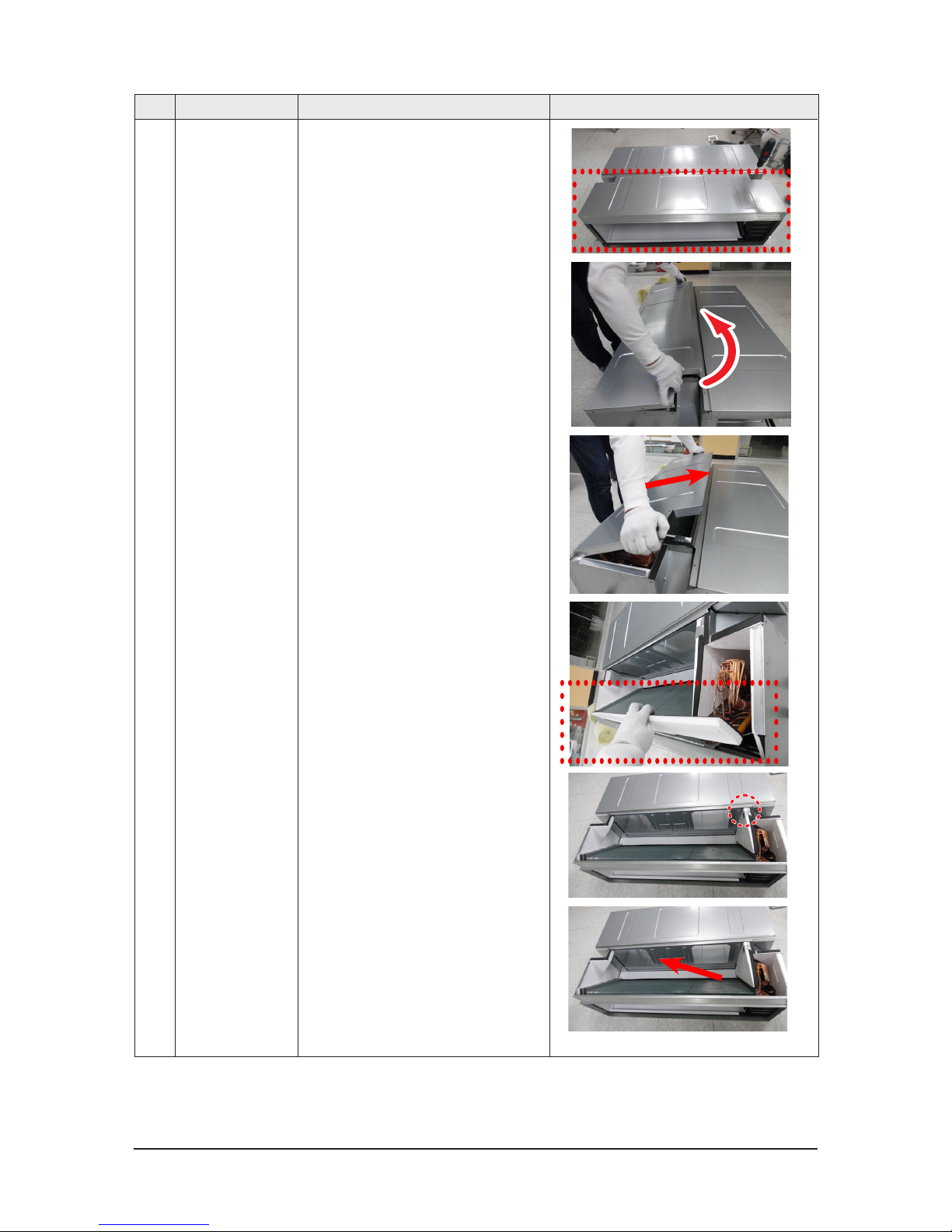
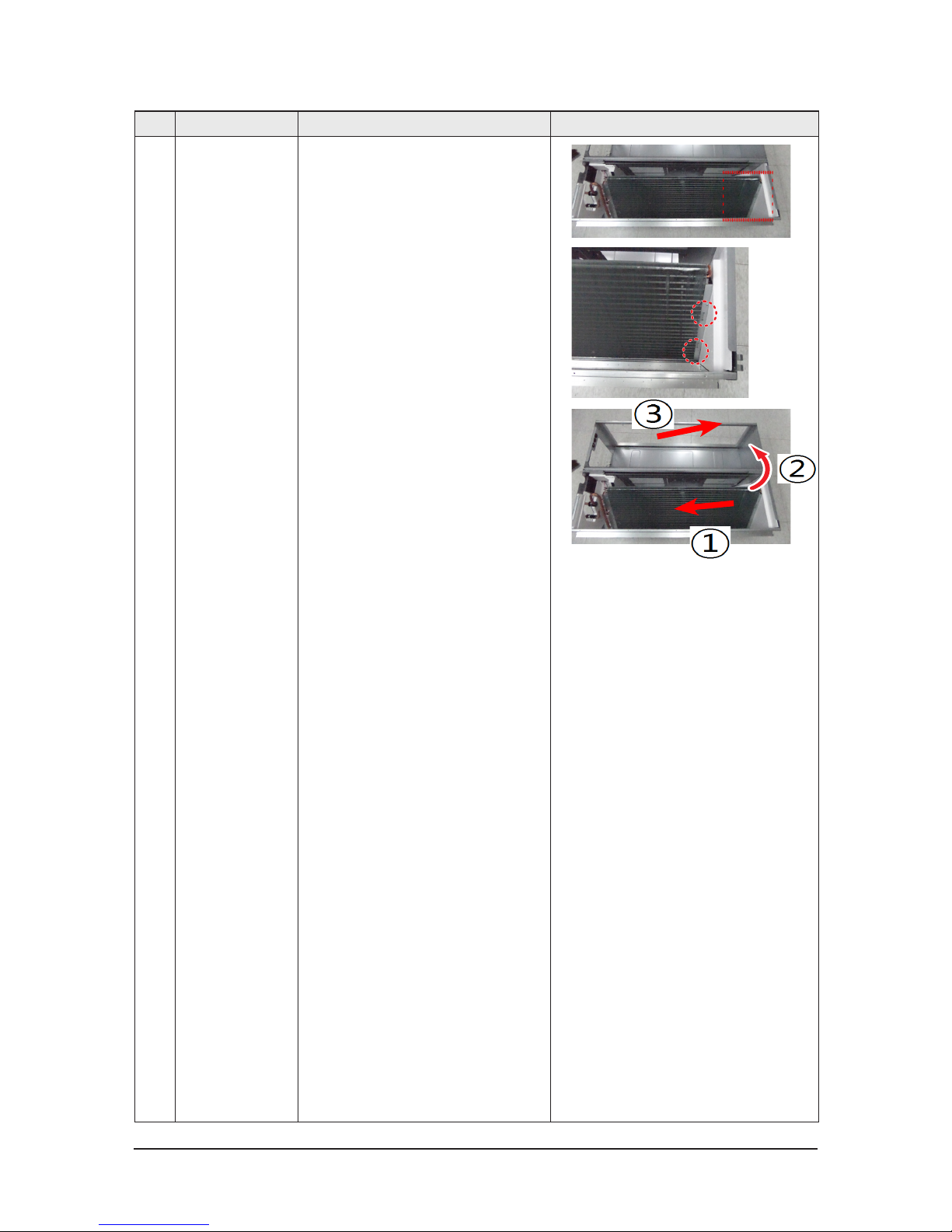
6)Disassemble The Evap.
- Unscrew 2 screws
① Moving the Evap 2~5cm to pipe direction
② Holding the pipe side and then rotating the
opposite side
③ Moving the Evap in the direction of the
arrow 3
3-14
Samsung Electronics
■ AC160JXAFKH/AC160JXAFNH/AC180JXAFNH/AC180JXAPNH
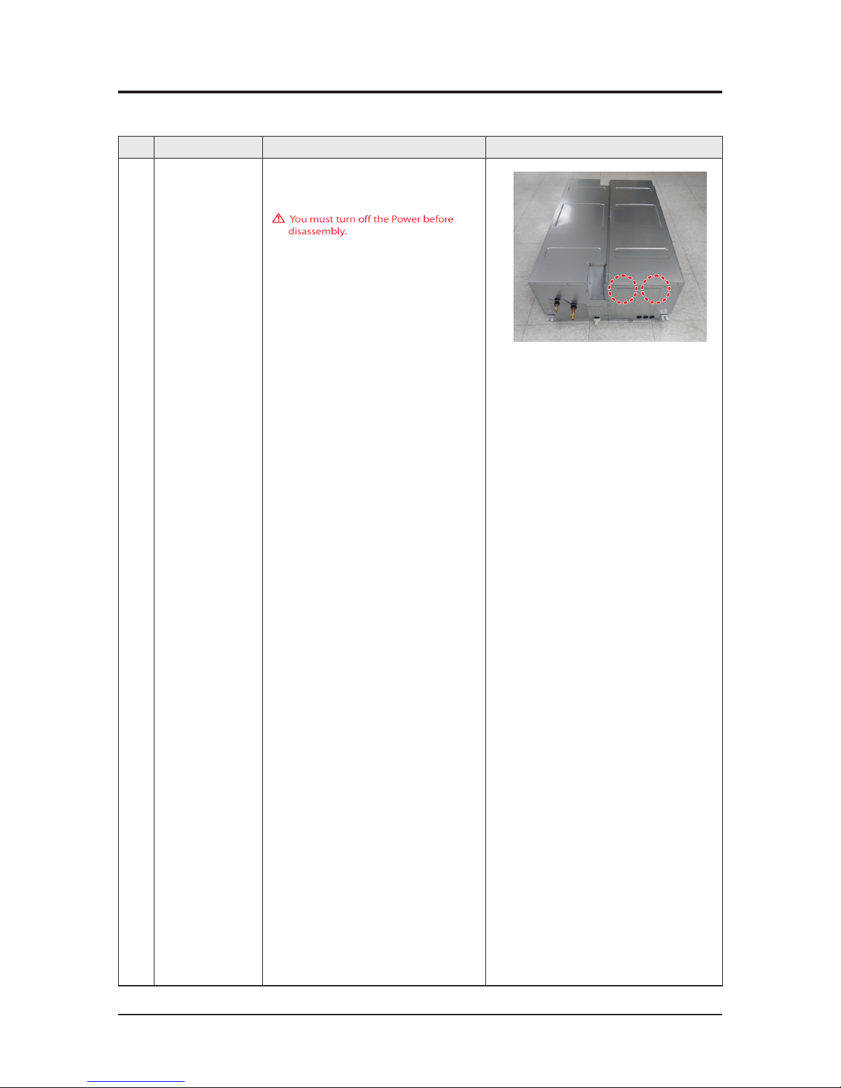
3-2 Outdoor Unit
No Parts Procedure Remark
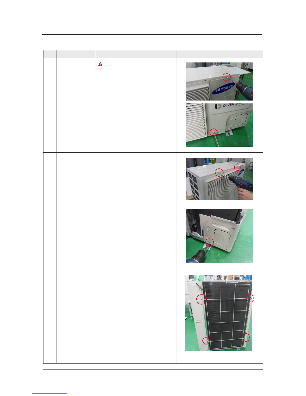
1 Cabi Front RH
You must turn off the Power before
disassembly.
1) Unscrew and remove two mounting
screw in the Cabinet Front RH.
(Use +Screw Driver)
2 Cabi Top
1) Unscrew and remove 9 screws
on each side of the Cabinet-Top.
(Use +Screw Driver)
3 Cabi Install Front
1) Unscrew and remove 1 screw
in the Cabinet-Install Front.
(Use +Screw Driver)
4 Guard Cond
1) Pull the sensor from Guard Cond.
2) Unscrew and remove 4 screws
in the Guard Cond.
(Use +Screw Driver)
Samsung Electronics
3-15
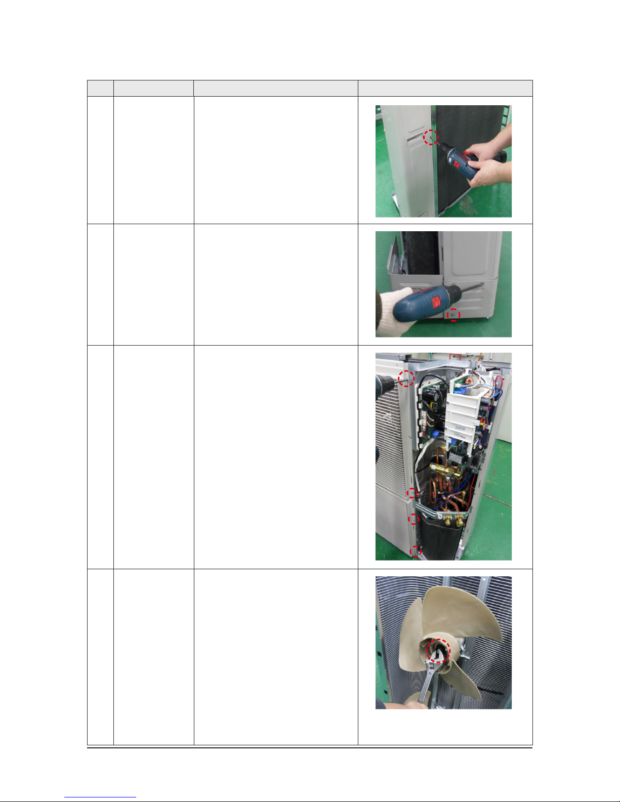
No Parts Procedure Remark
5 Cabi Back RH
1) Pull the sensor from Cabi Back RH.
2) Unscrew and remove 4 screws
on each side of the Cabinet Back RH.
(Use +Screw Driver)
6 Cabi Install Back
1) Unscrew and remove 1 screw
in the Cabinet-Install Back.
(Use +Screw Driver)
7 Cabi Front LF
1) Unscrew and remove 10 screws
in the Cabinet-Front LF.
(Use +Screw Driver)
8 Fan
1) Turn 2 mounting nuts as shown in
the picture and remove it.
(Use Adjustable Wrench)

3-16
Samsung Electronics
No Parts Procedure Remark
9 Motor
1) Separate the Fan Propeller.
2) Unscrew and remove the 8 Motor
mounting
screws. (Use +Screw Driver)
3) Disconnect the Motor wire From
Ass'y Control Out.
10 Bracket Motor
1) Unscrew and remove 2 mounting
screws in Bracket Motor.
(Use +Screw Driver)
11 Control Out
1) Disconnect 4 Connecters From
Ass'y Control Out.
2) Unscrew and remove 1 mounting
screw in Control Out.
(Use +Screw Driver)
3) Separate Ass'y Control Out.
Samsung Electronics
3-17
No Parts Procedure Remark
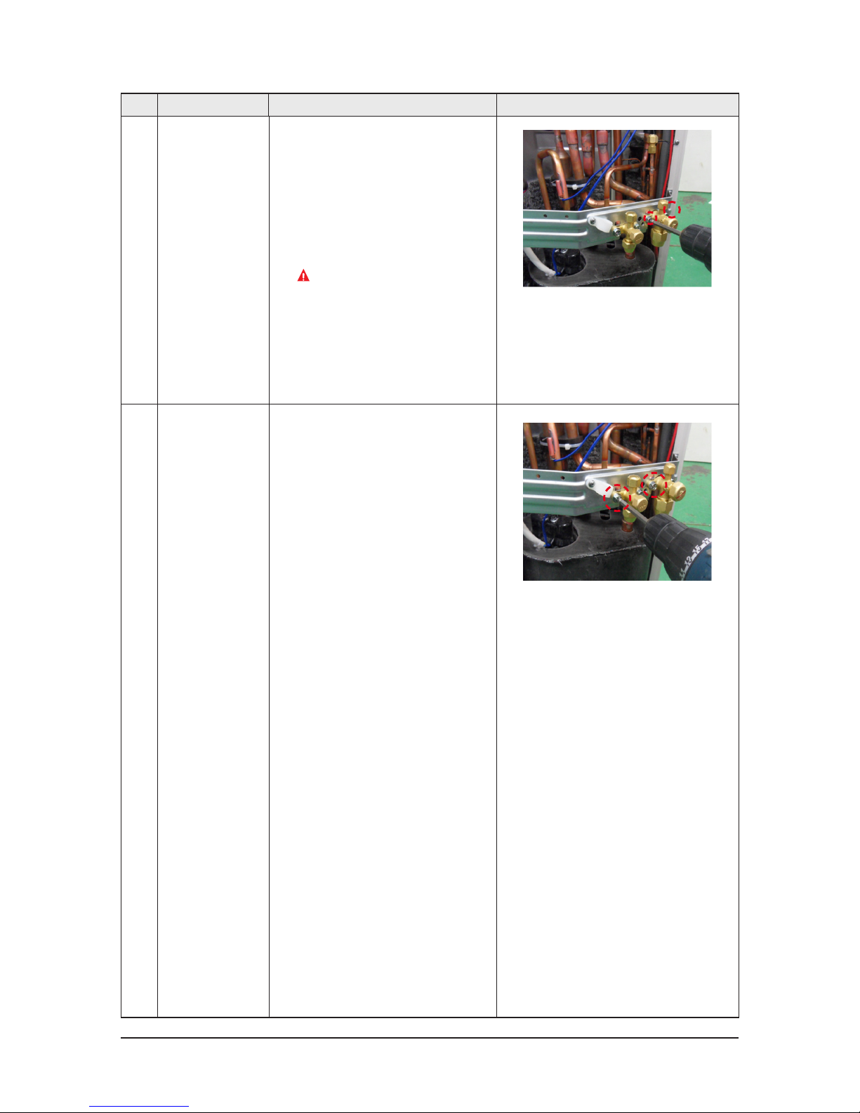
12 Assy 4way Valve
1) Purge the Coolant first.
2) Unscrew and remove 2 mounting
screws in Service Valve. (Use +Screw
Driver)
3) Separate the pipe from the
Entrance/Exit using a welder.
When removing the compres-
sor, Heat Exchanger, and Pipe,
purge the Coolant inside the
Compressor completely and
remove the pipe with a welding
flame.
13 Assy EEV Valve
1) Unscrew and remove 2 mounting
screws in Service Valve.
(Use +Screw Driver)
2) Separate the pipe from the Entrance/
Exit using a welder.
3-18 Samsung Electronics
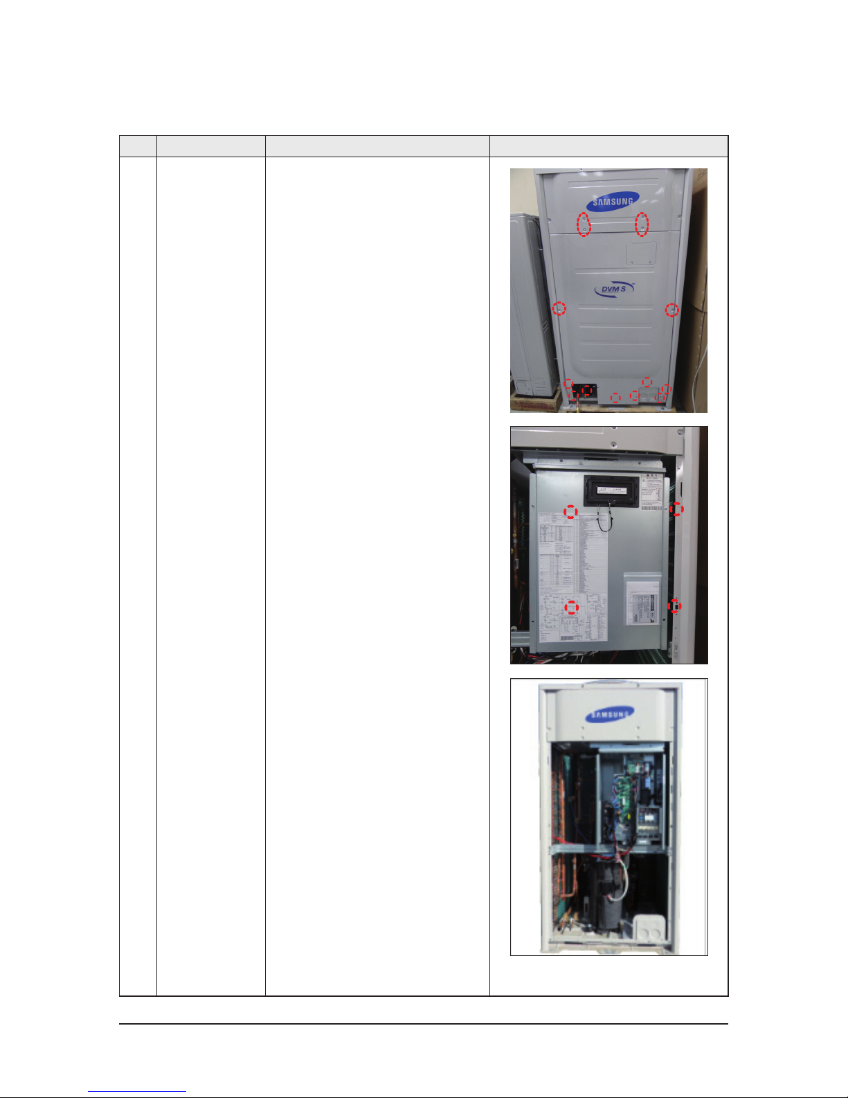
No. Parts Procedure Remark
1 Electrical
equipment Part
1) 14 screws that is fixing CABINET remove.(Use +
Screw driver)
2) Remove 4 screws that is fixing and separate
Cover Control Box.
(Use + Screw driver)
3) Power, Compressor, Valve, Motor, Sensor con-
nector connected to ASSY PCB remove.
■ AC200JXAFNH/AC200JXAPNH
 Loading...