

Rockwell Automation 1769-L23E-QB1B, 1769-L23E-QBFC1B, 1769-L23-QBFC1B Installation Instructions Manual
Page 1

Installation Instructions
CompactLogix Packaged Controllers
Catalog Numbers 1769-L23E-QB1B, 1769-L23E-QBFC1B, 1769-L23-QBFC1B
Topic Page
Important User Information 2
Before You Begin 4
Restrictions 4
Parts 5
Required System Components 6
Installation Checklist 7
Packaged Controller Dimensions 8
Install the Battery 10
Connect Expansion Modules (optional) 11
Panel Mount the System 13
DIN-rail Mount the System 13
Wiring Power to the System 15
Wire the I/O Removable Terminal Blocks 16
Expansion Module Wiring 27
Connect Using the RS-232 Connection 27
Connect Using the Ethernet Connection 28
Download and Install EDS Files 29
Download Packaged Controller Firmware 29
Use the AutoFlash Feature of RSLogix 5000 to Load Firmware 29
Use the ControlFlash Utility to Load Firmware 33
Select the Packaged Controller’s Operating Mode 36
Status Indicators 37
Specifications 45
Additional Resources 59
Page 2
2 CompactLogix Packaged Controllers
Important User Information
Solid state equipment has operational characteristics differing from those of electromechanical equipment.
Safety Guidelines for the Application, Installation and Maintenance of Solid State Controls (Publication
SGI-1.1
available from your local Rockwell Automation sales office or online at
http://literature.rockwellautomation.com
equipment and hard-wired electromechanical devices. Because of this difference, and also because of the
wide variety of uses for solid state equipment, all persons responsible for applying this equipment must
satisfy themselves that each intended application of this equipment is acceptable.
In no event will Rockwell Automation, Inc. be responsible or liable for indirect or consequential damages
resulting from the use or application of this equipment.
The examples and diagrams in this manual are included solely for illustrative purposes. Because of the many
variables and requirements associated with any particular installation, Rockwell Automation, Inc. cannot
assume responsibility or liability for actual use based on the examples and diagrams.
No patent liability is assumed by Rockwell Automation, Inc. with respect to use of information, circuits,
equipment, or software described in this manual.
) describes some important differences between solid state
Reproduction of the contents of this manual, in whole or in part, without written permission of Rockwell
Automation, Inc., is prohibited.
Throughout this manual, when necessary, we use notes to make you aware of safety considerations.
WARNING
IMPORTANT
ATTENTION
SHOCK HAZARD
Identifies information about practices or circumstances that can cause an explosion in
a hazardous environment, which may lead to personal injury or death, property
damage, or economic loss.
Identifies information that is critical for successful application and understanding of
the product.
Identifies information about practices or circumstances that can lead to personal injury
or death, property damage, or economic loss. Attentions help you identify a hazard,
avoid a hazard and recognize the consequences.
Labels may be on or inside the equipment, for example, a drive or motor, to alert
people that dangerous voltage may be present.
BURN HAZARD
Labels may be on or inside the equipment, for example, a drive or motor, to alert
people that surfaces may reach dangerous temperatures.
Publication 1769-IN082A-EN-P - July 2008
Page 3
CompactLogix Packaged Controllers 3
North American Hazardous Location Approval
The following information applies when operating
this equipment in hazardous locations.
Products marked "CL I, DIV 2, GP A, B, C, D" are suitable for use in
Class I Division 2 Groups A, B, C, D, Hazardous Locations and
nonhazardous locations only. Each product is supplied with
markings on the rating nameplate indicating the hazardous
location temperature code. When combining products within a
system, the most adverse temperature code (lowest "T" number)
may be used to help determine the overall temperature code of
the system. Combinations of equipment in your system are subject
to investigation by the local Authority Having Jurisdiction at the
time of installation.
WARNING
EXPLOSION HAZARD -
• Do not disconnect equipment
unless power has been removed
or the area is known to be
nonhazardous.
• Do not disconnect connections to
this equipment unless power has
been removed or the area is
known to be nonhazardous.
Secure any external connections
that mate to this equipment by
using screws, sliding latches,
threaded connectors, or other
means provided with this product.
• Substitution of components may
impair suitability for Class I,
Division 2.
• If this product contains batteries,
they must only be changed in an
area known to be nonhazardous.
Informations sur l’utilisation de cet équipement en
environnements dangereux.
Les produits marqués "CL I, DIV 2, GP A, B, C, D" ne conviennent
qu'à une utilisation en environnements de Classe I Division 2
Groupes A, B, C, D dangereux et non dangereux. Chaque produit
est livré avec des marquages sur sa plaque d'identification qui
indiquent le code de température pour les environnements
dangereux. Lorsque plusieurs produits sont combinés dans un
système, le code de température le plus défavorable (code de
température le plus faible) peut être utilisé pour déterminer le
code de température global du système. Les combinaisons
d'équipements dans le système sont sujettes à inspection par les
autorités locales qualifiées au moment de l'installation.
AVERTISSEMENT
RISQUE D’EXPLOSION –
• Couper le courant ou s'assurer
que l'environnement est classé
non dangereux avant de
débrancher l'équipement.
• Couper le courant ou s'assurer
que l'environnement est classé
non dangereux avant de
débrancher les connecteurs. Fixer
tous les connecteurs externes
reliés à cet équipement à l'aide
de vis, loquets coulissants,
connecteurs filetés ou autres
moyens fournis avec ce produit.
• La substitution de composants
peut rendre cet équipement
inadapté à une utilisation en
environnement de Classe I,
Division 2.
• S'assurer qu e l'environnement est
classé non dangereux avant de
changer les piles.
Environment and Enclosure
ATTENTION
This equipment is intended for use in a Pollution Degree 2 industrial environment, in overvoltage
Category II applications (as defined in IEC publication 60664-1), at altitudes up to 2000 m (6562 ft)
without derating.
This equipment is considered Group 1, Class A industrial equipment according to IEC/CISPR Publication
11. Without appropriate precautions, there may be potential difficulties ensuring electromagnetic
compatibility in other environments due to conducted as well as radiated disturbance.
This equipment is supplied as open-type equipment. It must be mounted within an enclosure that is
suitably designed for those specific environmental conditions that will be present and appropriately
designed to prevent personal injury resulting from accessibility to live parts. The enclosure must have
suitable flame-retardant properties to prevent or minimize the spread of flame, complying with a flame
spread rating of 5VA, V2, V1, V0 (or equivalent) if non-metallic. The interior of the enclosure must be
accessible only by the use of a tool. Subsequent sections of this publication may contain additional
information regarding specific enclosure type ratings that are required to comply with certain product
safety certifications.
In addition to this publication, see:
•Industrial Automation Wiring and Grounding Guidelines, publication 1770-4.1
installation requirements.
•NEMA Standards publication 250 and IEC publication 60529, as applicable, for explanations of the
degrees of protection provided by different types of enclosure.
, for additional
Publication 1769-IN082A-EN-P - July 2008
Page 4
4 CompactLogix Packaged Controllers
Prevent Electrostatic Discharge
ATTENTION
This equipment is sensitive to electrostatic discharge, which can cause internal damage
and affect normal operation. Follow these guidelines when you handle this equipment:
• Touch a grounded object to discharge potential static.
• Wear an approved grounding wriststrap.
• Do not touch connectors or pins on component boards.
• Do not touch circuit components inside the equipment.
• Use a static-safe workstation, if available.
• Store the equipment in appropriate static-safe packaging when not in use.
Before You Begin
This section contains information you should understand before installing the
CompactLogix packaged controller.
Restrictions
The maximum amount of expansion modules that can be used with the packaged
controllers is two. Within that limit, the number of expansion I/O modules that can
be attached to the packaged controller depends on the bus current draw of the
modules being attached.
Each packaged controller has a specified amount of available bus current as shown
in this table.
Packaged Controller Bus Current and Expansion Module Limits
Cat. No. Total Available 5V DC Bus Current
1769-L23E-QB1B 1 A (1000 mA)
1769-L23E-QBFC1B 450 mA
1769-L23-QBFC1B 800 mA
To determine the number of expansion I/O modules you can add, total the bus
current draw (maximum) of your planned expansion I/O modules and the end cap.
If your result is less than the packaged controller’s maximum available bus current,
you are within the expansion I/O limit of your packaged controller.
Publication 1769-IN082A-EN-P - July 2008
Page 5
CompactLogix Packaged Controllers 5
Example of Expansion I/O Calculation:
In this example, these expansion I/O modules and bus current draws are planned
for use with the 1769-L23E-QBFC1B packaged controller.
Planned Expansion I/O Module
1769-OV16 Sink Output Module 200 mA
1769-IF4 Analog Input Module 105 mA
1769-ECR End Cap 5 mA
Total Bus Current Draw: 310 mA
(1)
The maximum bus current draw specification for each Compact I/O module is available in the Compact I/O Selection Guide,
publication
power supply requirements.
1769-SG002. This publication also provides further explanation of and a table for the calculation of Compact I/O
Bus Current Draw, max
(1)
The total bus current draw of the Compact I/O modules (310 mA) is less than the
total available bus current of the packaged controller (450 mA). These planned
expansion I/O modules are within the limits of the 1769-L23E-QBFC1B packaged
controller.
Parts (included with the packaged controller)
These components are included with your CompactLogix packaged controller.
Cat. No. Part
1747-KY Key
1769-BA Battery
1769-ECR End cap
Parts (optional, not included with the packaged controller)
In addition to the parts included with the packaged controller, you may choose to
use these components specific to your application.
If using Then use this component
RS-232 port to connect to the packaged
controller.
EtherNet/IP port to connect to the packaged
controller.
Panel mount method to install the packaged
controller.
1756-CP3 or 1747-CP3 serial cable.
Standard Ethernet cable with an RJ45 connector, or, for
industrial grade requirements, 1585J Ethernet
connectivity media.
4…8 M4 or #8 panhead screws (depending on the number
of expansion modules used).
Publication 1769-IN082A-EN-P - July 2008
Page 6

6 CompactLogix Packaged Controllers
Replacement Parts
These CompactLogix packaged controller replacement parts are available for order.
Catalog No. Description Compatible Packaged Controllers
1769-BA CompactLogix packaged controller
battery
1769-ECR Compact right end cap 1769-L23E-QB1B, 1769-L23E-QBFC1B, and
1769-RDQB CompactLogix packaged controller door
1769-RDQBFC CompactLogix packaged controller door 1769-L23E-QBFC1B and 1769-L23-QBFC1B
1769-L23E-QB1B, 1769-L23E-QBFC1B, and
1769-L23-QBFC1B
1769-L23-QBFC1B
1769-L23E-QB1B
Required Tools
The only tool required for the installation of the CompactLogix packaged controller
is a medium-sized Phillips-head screwdriver.
Required System Components
Use these system components with your CompactLogix packaged controller.
Software Component Version
RSLogix 5000 17.00 or later
RSLinx Classic
(1)
You may use an earlier version of RSLinx software, however, if you do so,
you must download and install the EDS files specific to these controllers.
Also, if you are using Windows Vista, you must use RSLinx Classic
software, version 2.54.
2.52
(1)
Publication 1769-IN082A-EN-P - July 2008
Page 7

CompactLogix Packaged Controllers 7
Installation Checklist
This table lists tasks that must be completed to fully install and begin using your
packaged controller.
9
Installation Tasks
Install the Battery
Connect Expansion Modules (optional)
Panel Mount the System or DIN-rail Mount the System
Minimum Spacing Requirements
Grounding Considerations
Wire the I/O Removable Terminal Blocks
Connect Using the RS-232 Connection
Download and Install EDS Files
Download and Install Controller Firmware
Use the AutoFlash Feature of RSLogix 5000 to Load Firmware
or Use the ControlFlash Utility to Load Firmware
Publication 1769-IN082A-EN-P - July 2008
Page 8
8 CompactLogix Packaged Controllers
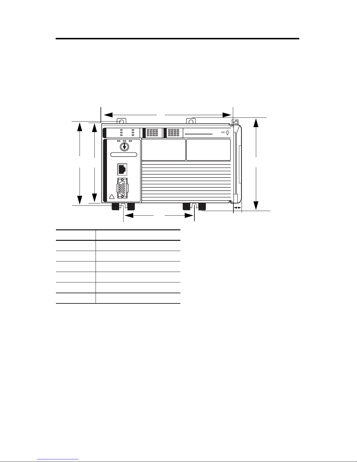
Packaged Controller Dimensions
1769-L23E-QB1B Packaged Controller
The 1769-L23E-QB1B controller has these approximate dimensions.
a
CompactLogix L23E
b
c
Measurement Dimension, approx.
a 185.2 mm (7.29 in)
b 123.86 mm (4.88 in)
c 118 mm (4.65 in)
d 132 mm (5.20in)
e 132.9 mm (5.23 in)
f 18 mm (.71 in)
d
e
f
Publication 1769-IN082A-EN-P - July 2008
Page 9
CompactLogix Packaged Controllers 9
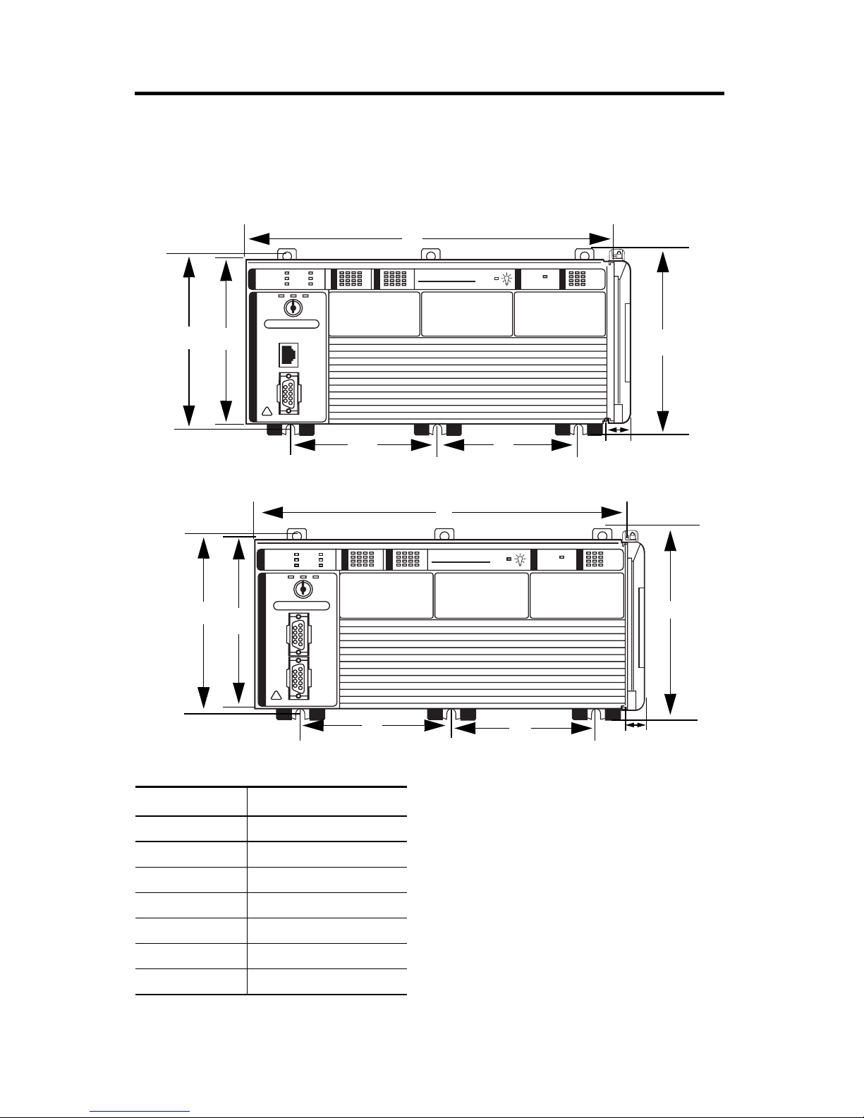
1769-L23E-QBFC1B and 1769-L23-QBFC1B Packaged Controllers
The 1769-L23E-QBFC1B and 1769-L23-QBFC1B packaged controllers have these
approximate dimensions.
a
CompactLogix L23E
b
c
e
f
g
d
a
I/O
RUN
OK
FORCE
BATT
DCH 0
b
b
c
e
CompactLogix L23
d
f
g
Measurement
(1)
Dimension, approx.
a 249.25 mm (9.81 in)
b 123.86 mm (4.88 in)
c 118 mm (4.65 in)
d 132 mm (5.20in)
e 98.475 mm (3.88 in)
f 98.475 mm (3.88 in)
g 18 mm (.71 in)
(1)
Applies to both the 1769-L23E-QBFC1B and
1769-L23-QBFC1B packaged controllers.
Publication 1769-IN082A-EN-P - July 2008
Page 10
10 CompactLogix Packaged Controllers
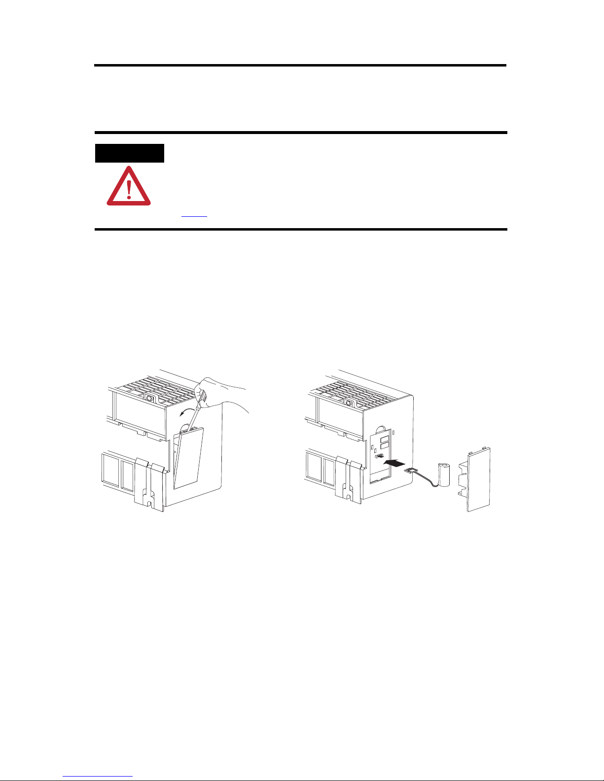
Install the Battery
Complete these steps to install the battery on your packaged controller.
WARNING
When you connect or disconnect the battery an electrical arc can occur. This could cause
an explosion in hazardous location installations. Be sure that the area is nonhazardous
before proceeding.
For Safety information on the handling of lithium batteries, including handling and
disposal of leaking batteries, see Guidelines for Handling Lithium Batteries, publication
AG 5-4
.
1. Open the battery door on the left side of the packaged controller.
2. Carefully attach the battery connector to the port located inside the
packaged controller.
3. Insert the battery, wires down, in the slot on the battery door.
4. Close the battery door.
Publication 1769-IN082A-EN-P - July 2008
Page 11
CompactLogix Packaged Controllers 11
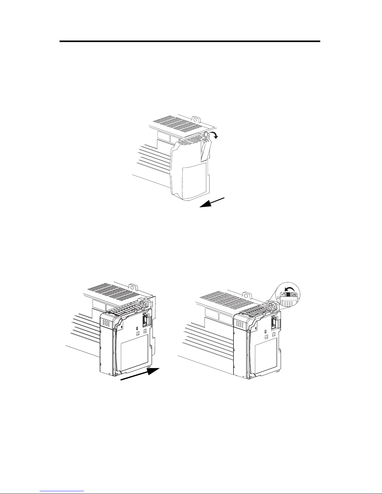
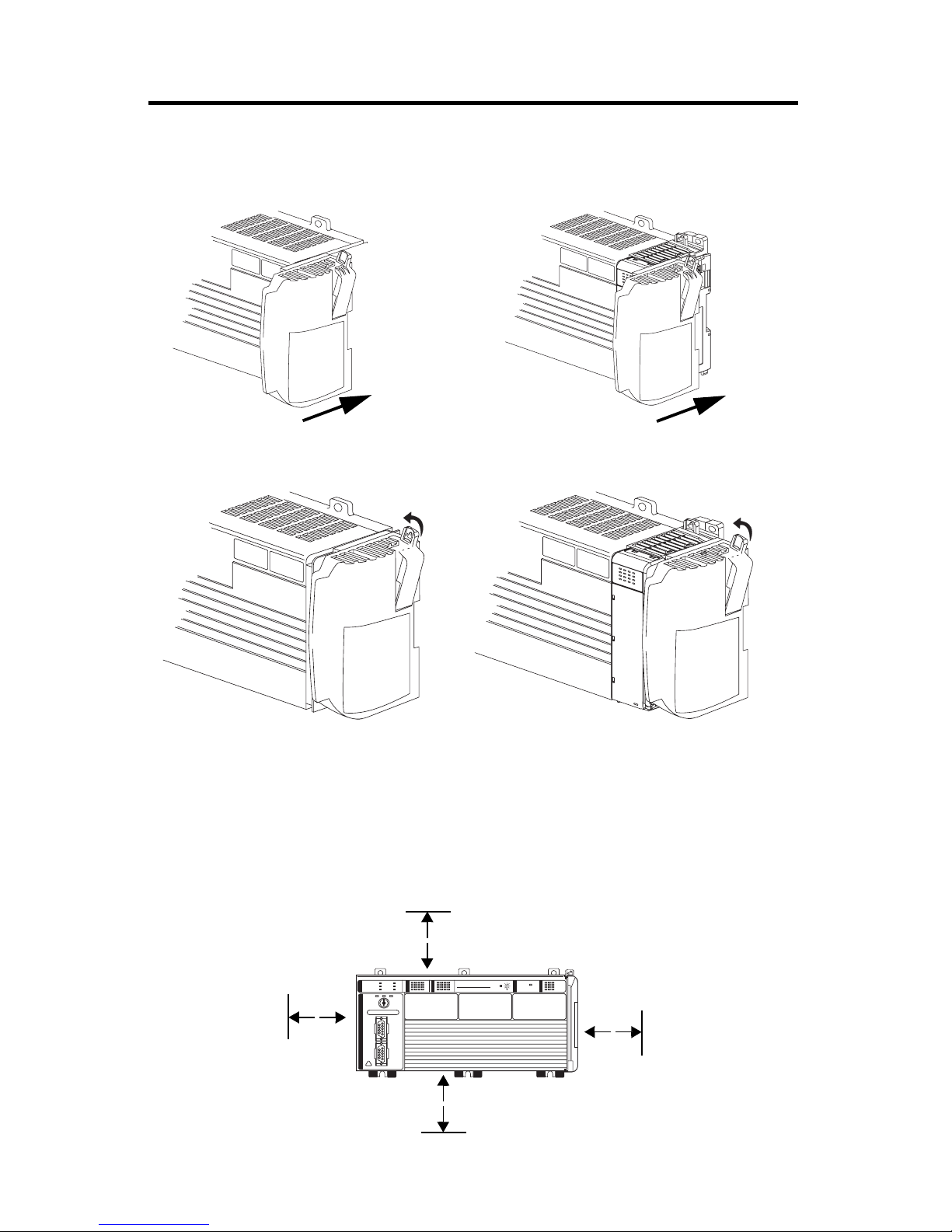
Connect Expansion Modules (optional)
If using expansion modules with your packaged controller, complete these steps to
attach the modules.
1. Remove the end cap by unlocking it and sliding it forward.
2. Align the tongue-and-groove slots of the expansion module with those on
the right end of the packaged controller.
3. Slide the module onto the packaged controller.
4. Close the locking tab on the top of the module.
5. If using another expansion module, complete steps 2…4 for the second
module.
Publication 1769-IN082A-EN-P - July 2008
Page 12
12 CompactLogix Packaged Controllers
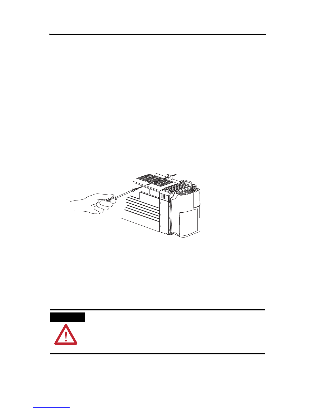
6. Align the tongue-and-groove slots of the end cap with those on the right of
the packaged controller or expansion module.
7. Close the locking tab located on the top of the end cap.
Minimum Spacing Requirements
When using any of the CompactLogix packaged controllers, maintain spacing from
enclosure walls, wireways, and adjacent equipment. Allow 50 mm (1.97 in.) of
space on all sides, as shown. This provides ventilation and electrical isolation.
50 mm
(1.97 in)
Publication 1769-IN082A-EN-P - July 2008
50 mm
(1.97 in)
I/O
RUN
OK
FORCE
BATT
DCH 0
CompactLogix L23
50 mm
(1.97 in)
50 mm
(1.97 in)
Page 13
CompactLogix Packaged Controllers 13
Panel Mount the System
To mount your system to a panel, complete these steps.
1. Using the assembled system as a template, carefully mark the center of all
mounting holes on the panel.
2. Remove the system and drill and tap the mounting holes for the
recommended M4 or #8 screws.
3. Place the grounding panel (if used) and CompactLogix system on the panel
to check for proper hole alignment.
4. Insert the recommended screws into the mounting tabs on the packaged
controller and expansion modules (if used) and tighten.
DIN-rail Mount the System
To mount your system on a DIN rail, complete these steps.
The packaged controller can be mounted on these DIN rails:
• EN 50 022 - 35 x 7.5 mm (1.38 x 0.30 in.)
• EN 50 022 - 35 x 15 mm (1.38 x 0.59 in.)
ATTENTION
1. Before mounting the packaged controller on a DIN rail, close the DIN-rail
latches.
When this product is grounded through the DIN rail to chassis ground, use zinc plated
yellow-chromate steel DIN rail to assure proper grounding. The use of other DIN rail
materials (for example, aluminum or plastic) that can corrode, oxidize, or are poor
conductors, can result in improper or intermittent grounding. Secure DIN rail to
mounting surface approximately every 200 mm (7.8 in.) and use end-anchors
appropriately.
Publication 1769-IN082A-EN-P - July 2008
Page 14
14 CompactLogix Packaged Controllers
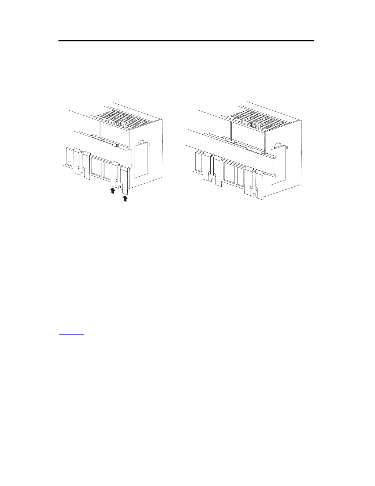
2. Press the DIN rail mounting area of the packaged controller against the DIN
rail.
The latches momentarily open and lock into place on the DIN rail
3. Press the DIN rail mounting area of the packaged controller against the DIN
rail.
The latches momentarily open and lock into place on the DIN rail.
Grounding Considerations
This product is intended to be mounted to a well-grounded mounting surface such
as a metal panel. Additional grounding connections from the packaged controller’s
mounting tabs or DIN rail (if used) are not required unless the mounting surface
cannot be grounded.
Refer to the Industrial Automation Wiring and Grounding Guidelines, publication
1770-4.1
for additional information.
Publication 1769-IN082A-EN-P - July 2008
Page 15
CompactLogix Packaged Controllers 15
Wiring Power to the System
Use this diagram as a reference when wiring the required 24V DC power to your
system.
WARNING
For more information about replacing the fuse, see the Fuse Replacement Procedure in
the Compact Expansion Power Supplies installation instructions, publication 1769-IN028
IMPORTANT
Power Wiring Diagram
To comply with the CE Low Voltage Directive (LVD), this equipment and all connected I/O
must be powered from a source compliant with one of the following:
• Do not connect directly to line voltage. Line voltage must be supplied by a suitable,
approved isolating transformer or power supply having short-circuit capacity not
exceeding 100 VA maximum or equivalent.
• Explosion hazard, do not remove or replace fuses on the packaged controller unless
power has been disconnected or the area is known to be free of ignitible
concentrations of flammable gases or vapors.
.
• Safety Extra Low Voltage (SELV).
• Protected Extra Low Voltage (PELV).
CompactLogix L23E
Power Wire Size and Terminal Screw Torque
Wire Type Wire Size Terminal Screw Torque
Solid or stranded
Cu: 75 °C (167 °F)
No Connection
No Connection
+24 V DC
DC Neutral
System Power Ground
0.25... 2.5 mm2 (22...14 AWG) 1.27 Nm (11.24 inz lb)
Publication 1769-IN082A-EN-P - July 2008
Page 16
16 CompactLogix Packaged Controllers
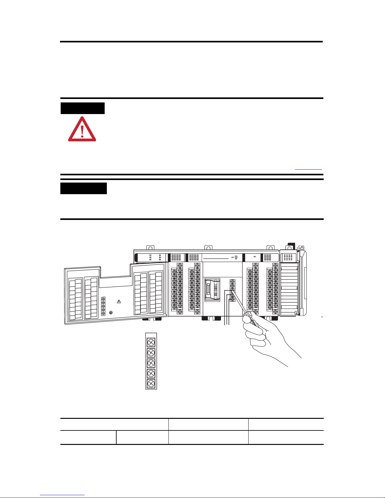
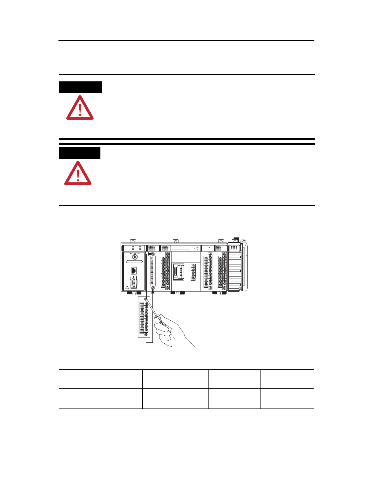
Wire the I/O Removable Terminal Blocks
WARNING
ATTENTION
• When you connect or disconnect the Removable Terminal Block (RTB) with field side
power applied, an electrical arc can occur. This could cause an explosion in hazardous
location installations.
• If you connect or disconnect wiring while the field-side power is on, an electrical arc
can occur. This could cause an explosion in hazardous location installations.
Be sure that power is removed or the area is nonhazardous before proceeding.
• Mis-wiring the removable terminal blocks to an AC power source causes damage
to the packaged controller.
• Be careful when stripping wires. Wire fragments that fall into an removable
terminal block could cause damage at power up. Once wiring is complete, ensure
the removable terminal blocks are free of all metal fragments.
• When wiring I/O removable terminal blocks, tighten terminal screws with care.
Excessive tightening can strip a screw.
To begin wiring your embedded I/O removable terminal blocks, loosen the screws
at the top and bottom of the removable terminal block and remove the removable
terminal block from the packaged controller.
CompactLogix L23E
I/O Removable Terminal Block Wire Size and Screw Torques
Wire Type Wire Size Terminal Screw
Solid or
stranded
Cu: 75
°C (167 °F)
Reference the wiring diagrams specific to each type of embedded I/O as shown in
the following pages.
Publication 1769-IN082A-EN-P - July 2008
0.5... 0.8 mm2
(20...18 AWG)
31761-M
Torque
0.68 Nm (6 in
Retaining Screw
To rq ue
z lb) 0.46 Nm (4.1 inz lb)
Page 17
CompactLogix Packaged Controllers 17
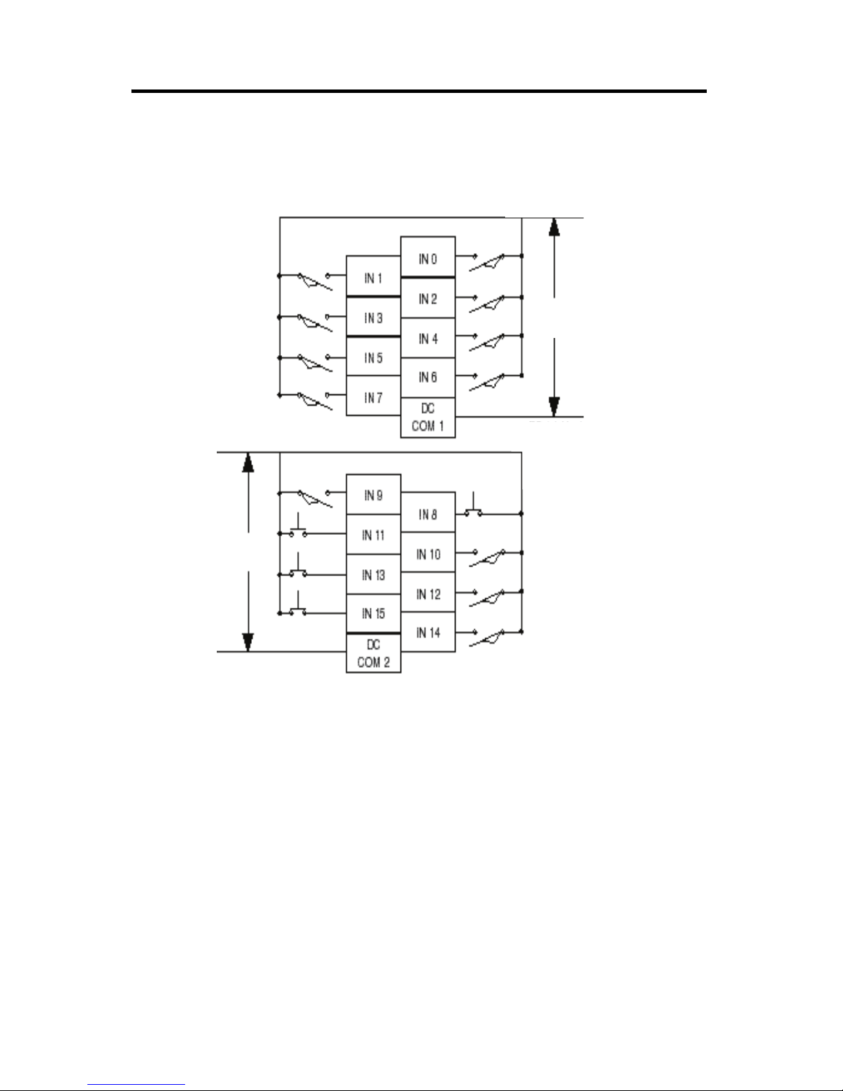
DC Inputs Wiring Diagram
+ DC (sinking)
- DC (sourcing)
(1)
+ DC (sinking)
- DC (sourcing)
24V DC
+ DC (sinking)
- DC (sinking)
- DC (sourcing)
+ DC (sourcing)
24V DC
- DC (sinking)
+ DC (sourcing)
(1)
Sinking/Sourcing Inputs - Sourcing/sinking describes the current flow between the I/O and the field device. Sourcing
I/O circuits supply (source) current to sinking field devices. Sinking I/O circuits are driven by a current sourcing field device.
Field devices connected to the negative side (DC Common) of the field power supply are sinking field devices. Field devices
connected to the positive side (+V) of the field supply are sourcing field devices. Europe: DC sinking input and sourcing
output circuits are the commonly used options.
Publication 1769-IN082A-EN-P - July 2008
Page 18
18 CompactLogix Packaged Controllers
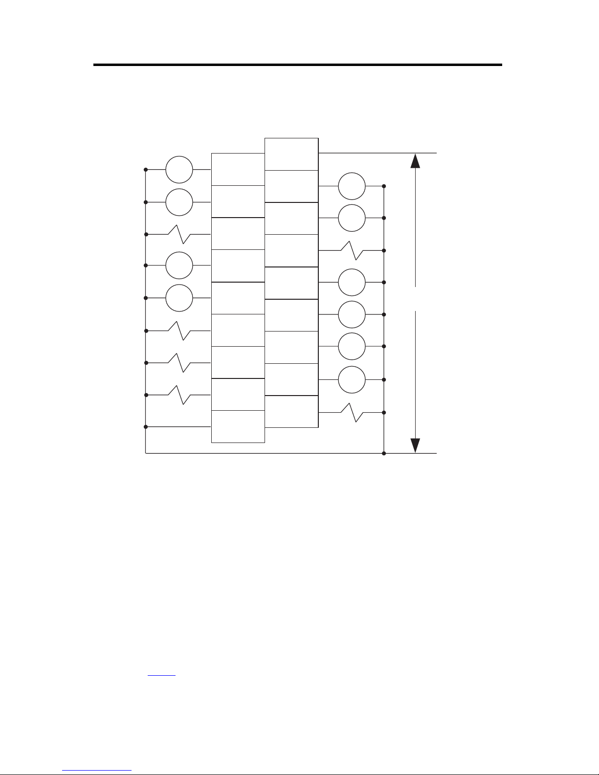
DC Outputs Wiring Diagram
CR
CR
CR
CR
(1)(2)
OUT 0
OUT 2
OUT 4
OUT 6
OUT 8
OUT 10
OUT 12
+VDC
OUT 1
OUT 3
OUT 5
OUT 7
OUT 9
OUT 11
+DC
CR
CR
CR
24V dc(source)
CR
CR
OUT 13
CR
OUT 14
OUT 15
DC COM
-DC
(1)
Recommended Surge Suppression - Use a 1N4004 diode reverse-wired across the load for transistor outputs switching 24V
DC inductive loads. For additional details, refer to Industrial Automation Wiring and Grounding Guidelines, Allen-Bradley
publication 1770-4.1
(2)
Sourcing Output - Source describes the current flow between the I/O and the field device. Sourcing output circuits supply
(source) current to sinking field devices. Field devices connected to the negative side (DC Common) of the field power
supply are sinking field devices. Field devices connected to the positive side (+V) of the field supply are sourcing field
devices. Europe: DC sinking input and sourcing output circuits are the commonly used options.
.
Publication 1769-IN082A-EN-P - July 2008
Page 19

CompactLogix Packaged Controllers 19
Analog I/O Wiring Diagrams
Read and consider this information before wiring your analog I/O.
ATTENTION
IMPORTANT
Analog outputs may fluctuate for less than a second when power is applied or removed.
This characteristic is common to most analog outputs. While the majority of loads will
not recognize the short signal, take preventive measures to ensure that connected
equipment is not affected.
In environments where high-frequency noise may be present, it may be necessary to
directly ground cable shields to earth at the removable terminal block end and via a 0.1µF
capacitor at the sensor end.
• All analog I/O commons (ANLG COM) are connected in the analog I/O card
of the packaged controller. The analog common (ANLG COM) is not
connected to earth ground inside the packaged controller.
• Analog I/O channels are not isolated from each other.
• Use Belden 8761 (or equivalent) shielded wire.
• Under normal conditions, the drain wire and shield junction must be
connected to earth ground via a panel or DIN rail mounting screw at the
analog I/O removable terminal block end. Keep the shield connection to
ground as short as possible.
• To ensure optimum accuracy, limit overall cable impedance by keeping your
cable as short as possible. Plan to place the packaged controller as close to
your sensors or actuators as your application permits.
(1)
• If multiple power supplies are used with analog inputs:
– the power supply commons must be connected.
– do not exceed the specified isolation voltage.
• The embedded analog I/O does not provide loop power for analog inputs.
Use a power supply that matches the input transmitter specifications.
• Differential analog inputs are more immune to noise than single-ended
analog inputs.
• Voltage outputs (Vout 0+ and Vout 1+) of the analog I/O are referenced to
ANLG COM. Load resistance for a voltage output channel must be equal to
or greater than 1 KΩ.
• Current outputs (Iout 0+ and Iout 1+) of the analog I/O source current that
returns to ANLG COM. Load resistance for a current output channel must
remain between 0…300 Ω.
• Voltages on Vin+, V/Iin-, and Iin+ of the analog I/O must be within 0 to
+10V DC of analog common.
(1)
Cable length over 50 m (164.04 ft) may impact accuracy. For details, refer to the Compact Combination Analog I/O Module,
publication 1769-UM008
.
Publication 1769-IN082A-EN-P - July 2008
Page 20

20 CompactLogix Packaged Controllers
Differential Input Wiring Diagram
Belden 8761 cable (or equivalent)
+
Differential Voltage
–
V in 1+
V/I in 1 -
I in 1+
V in 3+
V/I in 3 -
I in 3+
ANLG Com
V out 1+
I out 1+
V in 0+
V/I in 0-
I in 0+
V in 2 +
V/I in 2-
I in 2+
ANLG Com
V out 0+
I out 0+
Earth ground the
shield locally at the
module.
Single-ended Sensor/Transmitter Types Wiring Diagram
Tr an sm it te r
Sensor/
Transmitter
Power Supply
(1) The sensor power supply must be rated at Class 2.
1769-IF4XOF2 Terminal Block
+
-
(1)
Current
Transmitter
+
Signal
Voltage Transmitter
Ground
+
Signal
V in 0+
I in 0+
V/I in 0 V in 1+
I in 1+
V/I in 1V in 2+
I in 2+
V/I in 2V in 3+
I in 3+
V/I in 3-
ANLG Com
ANLG Com
V out 0+
I out 0+
V out 1+
I out 1 +
Publication 1769-IN082A-EN-P - July 2008
Page 21

Mixed-input Transmitter Wiring Diagram
–
–
CompactLogix Packaged Controllers 21
Single-ended
Voltage
Transmitter
–
Differential
Voltage
Tra ns mi t te r
Differential
Current
Transmitter
Supply
2-Wire
Current
Transmitter
Sensor/
Tr an sm it te r
Power Supply
Signal
+
+
Signal
–
+
+
Signal
–
+
Signal
+
Analog I/O Terminal Block
V in 0+
I in 0+
V/I in 0 -
V in 1+
I in 1+
V/I in 1V in 2+
I in 2+
V/I in 2-
V in 3+
I in 3+
V/I in 3ANLG Com
ANLG Com
V out 0+
I out 0+
V out 1+
I out 1 +
+
(1)
–
(1) The sensor power supply must be rated at Class 2.
Analog Outputs Wiring Diagram
V in 0+
I in 0+
V/I in 0 -
V in 1+
I in 1+
V/I in 1-
Voltage Load
Earth Ground
Current Load
Earth Ground
V in 2+
I in 2+
V/I in 2V in 3+
I in 3+
V/I in 3ANLG Com
ANLG Com
V out 0+
I out 0+
V out 1+
I out 1 +
Publication 1769-IN082A-EN-P - July 2008
Page 22

22 CompactLogix Packaged Controllers
High-speed Counter Wiring Diagrams
Read and consider this information before wiring your high-speed counter.
ATTENTION
Disconnect power before wiring the HSC removable terminal block. This includes sensor
and packaged controller power.
• Input and output channels are isolated from the packaged controller. Input
channels are isolated from one another; output channels are not.
• Shielded cable is required for high-speed input signals A, B, and Z. Use
individually shielded, twisted-pair cable (or the type recommended by the
encoder manufacturer) for lengths up to 300 m (1000 ft).
• Route field wiring away from any other wiring and as far as possible from
sources of electrical noise, such as motors, transformers, contactors, and AC
devices.
• Routing field wiring in a grounded conduit can reduce electrical noise.
• If field wiring must cross AC or power cables, ensure that they cross at right
angles.
• Make sure the system is properly grounded using these guidelines:
– This product is intended to be mounted to a well-grounded mounting
surface such as a metal panel. Additional grounding connections from the
packaged controller’s mounting tabs or DIN rail (if used) are only
required when the mounting surface is non-conductive and cannot be
grounded.
– Keep the shield connection to ground as short as possible.
– Ground the shield drain wire only at the HSC input end, except where
high-frequency noise is present.
IMPORTANT
In environments where high-frequency noise may be present, it may be necessary to
directly ground cable shields to earth at the removable terminal block end and via a 0.1µF
capacitor at the sensor end.
• To establish optimum accuracy, limit overall cable impedance by keeping
cable as short as possible. Locate the packaged controller as close to input
devices as your application permits.
Publication 1769-IN082A-EN-P - July 2008
Page 23

HSC Differential Encoder Wiring
Cable
VS
GND
CompactLogix Packaged Controllers 23
(1)
+VDC
COM
Power
Supply
A1(+)
A1(–)
B1(+)
B1(–)
Z1(+)
Z1(–)
Allen-Bradley
845H Series
Differential
Encoder
A
A
B
B
Z
Z
Shield
Shield/housing
Connect only if housing is electronically
Earth
isolated from the motor and ground.
Inputs
(1) Refer to your encoder manual for proper cable type. The type of cable used should be twisted pair, individually shielded
cable with a maximum length of 300 m (1000 ft.).
Publication 1769-IN082A-EN-P - July 2008
Page 24

24 CompactLogix Packaged Controllers
HSC Single-ended Encoder Wiring Diagram
(1)
Cable
VS
GND
(2)
R
+VDC
COM
Power
Supply
A1(+)
A1(–)
B1(+)
B1(–)
Z1(+)
Z1(–)
Inputs
Allen-Bradley
845H Series
Single-ended
Encoder
Shield/housing
A
B
Z
Shield
Earth
Connect only if housing is
electronically isolated from the
motor and ground.
(1) Refer to your encoder manual for proper cable type. The type of cable used should be twisted-pair, individually shielded
cable with a maximum length of 300 m (1000 ft.).
(2) External resistors are required if they are not internal to the encoder. The pull-up resistor (R) value depends on the power
supply value. The table below shows the maximum resistor values for typical supply voltages. To calculate the maximum
resistor value, use this formula:
V
DC Vmin–()
R
-------------------------------------------=
Where:
Imin
R = maximum pull-up resistor value
VDC = power supply voltage
Vmin = 2.6V DC
Imin = 6.8 mA
Power Supply Voltage (V DC) Maximum Pull-up Resistor Value (R)
5V DC 352 Ω
12V DC 1382 Ω
24V DC 3147 Ω
(1)
Resistance values may change, depending upon your application.
The minimum resistor (R) value depends on the current sinking capability of the
encoder. Refer to your encoder’s documentation for more information.
Publication 1769-IN082A-EN-P - July 2008
(1)
Page 25

HSC Discrete Device Wiring
CompactLogix Packaged Controllers 25
+VDC
COM
Power
Supply
Proximity Sensor
VS
VS
OUT
COM
A1(+)
A1(–)
B1(+)
B1(–)
Z1(+)
Z1(–)
OUT
COM
VS
OUT
COM
Solid-state
Switch
(1)
R
Photo-electric Sensor with Open
Collector Sinking Output
(1) External resistors are required if they are not internal to the sensor. The pull-up resistor (R) value depends on the power
supply value. The table below shows the maximum resistor values for typical supply voltages. To calculate the maximum
resistor value, the following formula:
Module Inputs
V
DC Vmin–()
R
-------------------------------------------=
Imin
Where:
R = maximum pull-up resistor value
VDC = power supply voltage
Vmin = 2.6V DC
Imin = 6.8 mA
Power Supply Voltage (VDC) Maximum Pull-up Resistor Value (R)
(1)
5V DC 352 Ω
12V DC 1382 Ω
24V DC 3147 Ω
(1)
Resistance values may change, depending upon your application.
The minimum resistor (R) value depends on the current sinking capability of the
sensor. Refer to your sensor’s documentation for more information.
Publication 1769-IN082A-EN-P - July 2008
Page 26

26 CompactLogix Packaged Controllers
HSC Output Wiring
Basic wiring
ATTENTION
(1)
of HSC outputs
Mis-wiring the embedded HSC to an AC power source or applying reverse
polarity causes damage to the embedded HSC.
(2)
is shown below.
CR
OUT 0
OUT 2
OUT
DC COM
A0-
B0-
Z0-
A1-
B1-
Z1-
OUT DC
+5/24VDC
OUT 1
OUT 3
A0+
B0+
Z0+
A1+
B1+
Z1+
+DC
CR
CR
+5/24V dc
(1)
Recommended Surge Suppression - The embedded HSC has built-in suppression which is sufficient for most applications,
however, for high-noise applications, use a 1N4004 diode reverse-wired across the load for transistor outputs switching
24V DC inductive loads. For additional details, refer to Industrial Automation Wiring and Grounding Guidelines,
Allen-Bradley publication
(2)
Sourcing Output - Source describes the current flow between the I/O and the field device. Sourcing output circuits supply
(source) current to sinking field devices. Field devices connected to the negative side (DC Common) of the field power
supply are sinking field devices. Field devices connected to the positive side (+V) of the field supply are sourcing field
devices. Europe: DC sinking input and sourcing output circuits are the commonly used options.
Publication 1769-IN082A-EN-P - July 2008
1770-4.1.
-DC
Page 27

CompactLogix Packaged Controllers 27
Expansion Module Wiring
Use the wiring diagrams specific to your expansion module.
Module wiring diagrams are available at http://literature.rockwellautomation.com.
Connect Using the RS-232 Connection
1769-L23E-QB1B, 1769-L23-QBFC1B, and 1769-L23E-QBFC1B controllers
WARNING
To connect to your controller using the RS-232 (serial) connection, simply connect
the 9-pin female end of the serial cable to the serial port of the controller.
If you connect or disconnect the serial cable with power applied to this module or the
serial device on the other end of the cable, an electrical arc can occur. This could
cause an explosion in hazardous location installations.
Be sure that power is removed or the area is nonhazardous before proceeding.
Publication 1769-IN082A-EN-P - July 2008
Page 28

28 CompactLogix Packaged Controllers
Connect Using the Ethernet Connection
1769-L23E-QB1B and 1769-L23E-QBFC1B controllers
Complete these steps to connect to the controller using the Ethernet connection.
WARNING
If you connect or disconnect the Ethernet cable with power applied to this module or
any device on the network, an electrical arc can occur. This could cause an explosion in
hazardous location installations.
Be sure that power is removed or the area is nonhazardous before proceeding.
ATTENTION
Do not plug a DH-485 network cable or a NAP port cable into the Ethernet port.
Undesirable behavior and/or damage to the port may result.
1. Insert the RJ45 connector of the Ethernet cable into the Ethernet port located
on the front of the controller.
CompactLogix L23E
8 ------ NC
7 ------ NC
6 ------ RD5 ------ NC
4 ------ NC
3 ------ RD+
2 ------ TD1 ------ TD+
2. Use the BOOTP utility or RSLogix 5000 software to assign an IP address to
the controller.
The controller ships with BOOTP functionality enabled. This means that no
extra steps must be taken to make the controller work with a BOOTP utility.
For more information about setting the controller’s IP address (a network
parameter), see the EtherNet/IP Modules in Logix5000 Control Systems User
Manual, publication
ENET-UM001.
Publication 1769-IN082A-EN-P - July 2008
Page 29

CompactLogix Packaged Controllers 29
Download and Install EDS Files
If you have RSLinx software, version 2.52 or later, the most current EDS files were
installed with the software.
If you are using an earlier version of RSLinx software, you need to download and
install EDS files specific to each component of the packaged controller. This
includes firmware and icons specific to the packaged controller, its Ethernet
interface, virtual backplane, virtual adapter, and embedded I/O.
EDS files are available on the RSLogix 5000 software, version 17 CD, at
http://support.rockwellautomation.com, and at http://www.ab.com/networks/eds.
Download Packaged Controller Firmware
Packaged controller firmware is available on the RSLogix 5000 software CD or you
can download it from
http://support.rockwellautomation.com.
Use the AutoFlash Feature of RSLogix 5000 to Load Firmware
RSLogix 5000 lets you update your packaged controller firmware without having to
open the ControlFlash utility. You can load firmware via an Ethernet (preferred) or
serial connection.
IMPORTANT
1. Make sure the appropriate network connection is made and your network
driver is configured in RSLinx software.
2. Use RSLogix 5000 programming software to create a packaged controller
project.
3. Click RSWho to specify the controller path.
When upgrading your packaged controller firmware, it is extremely important to allow
the upgrade to complete without interruption.
If you interrupt the firmware upgrade either in the software or by disturbing the physical
media, you may render the packaged controller inoperable.
For more information about upgrading your CompactLogix packaged controller firmware,
see information posted at http://www.rockwellautomation.com/knowledgebase/
.
Publication 1769-IN082A-EN-P - July 2008
Page 30

30 CompactLogix Packaged Controllers
4. Select your packaged controller and click Download.
You may also choose to click Update Firmware to complete this process. If
you do so, skip to step 8.
A dialog box displays indicating that the project revision and controller
firmware revision are different.
5. Click Update Firmware.
Publication 1769-IN082A-EN-P - July 2008
Page 31

CompactLogix Packaged Controllers 31
6. Use the checkbox and pull-down to select your controller and firmware
revision.
7. Click Update.
8. Click Yes.
The firmware upgrade begins.
IMPORTANT
DO NOT INTERUPT THE FIRMWARE UPGRADE ONCE IT HAS BEGUN.
Interupting the firmware upgrade may result in an inoperable packaged controller.
Publication 1769-IN082A-EN-P - July 2008
Page 32

32 CompactLogix Packaged Controllers
During the firmware upgrade you see the status change as shown below.
Status Change
Continue to allow the firmware upgrade to complete without interuption.
When the firmware upgrade is complete, the Download dialog displays and
you may continue by dowloading your project to the packaged controller.
Publication 1769-IN082A-EN-P - July 2008
Page 33

CompactLogix Packaged Controllers 33
Use the ControlFlash Utility to Load Firmware
You can use the ControlFlash utility to load firmware via an Ethernet (preferred) or
serial connection.
IMPORTANT
When upgrading your packaged controller firmware, it is extremely important to allow
the upgrade to complete without interruption.
If you interrupt the upgrade either in ControlFlash software or by disturbing the physical
media, you may render the packaged controller inoperable.
For more information about upgrading your CompactLogix packaged controller firmware,
see information posted at http://www.rockwellautomation.com/knowledgebase/
1. Make sure the appropriate network connection is made and your network
driver is configured in RSLinx software.
2. Start the ControlFlash utility.
3. When the Welcome dialog appears, click Next.
4. Choose the catalog number of the packaged controller and click Next.
5. Expand the network until you see your packaged controller and select it.
.
6. Click OK.
7. Choose the revision level to which you want to update the packaged
controller and click Next.
Publication 1769-IN082A-EN-P - July 2008
Page 34

34 CompactLogix Packaged Controllers
8. Click Finish and then click Yes.
The firmware upgrade begins.
IMPORTANT
During the firmware upgrade you see the status change as shown below.
Status
Change
Continue to allow the firmware upgrade to complete without interuption.
DO NOT INTERUPT THE FIRMWARE UPGRADE ONCE IT HAS BEGUN.
Interupting the firmware upgrade may result in an inoperable packaged controller.
Status
Change
Publication 1769-IN082A-EN-P - July 2008
Page 35

CompactLogix Packaged Controllers 35
The Upgrade Status dialog box indicates that the firmware upgrade has been
successfully completed.
9. Click OK.
10. To close the ControlFlash utility, click Cancel and then click Yes.
Publication 1769-IN082A-EN-P - July 2008
Page 36

36 CompactLogix Packaged Controllers
Select the Packaged Controller’s Operating Mode
Use the keyswitch on the front panel of the packaged controller to select the
packaged controller’s operating mode.
This table explains the three modes (keyswitch positions) available on the front
panel of the packaged controller.
Operating Mode Selection
Use this
operating
mode
RUN • Upload projects.
PROG • Disable outputs.
To achieve these tasks
• Run the program and enable outputs.
Note: When the keyswitch is in the RUN position, you cannot change the operating mode
by using the Controller Status menu in RSLogix
• Upload/download projects.
• Create, modify, and delete tasks, programs, or routines.
• Stop the execution (scanning) of tasks. That is, the packaged controller does not
execute (or scan) tasks while the keyswitch is in the Prog position.
Note: When the keyswitch is in the PROG position, you cannot change the operating
mode by using the Controller Status menu in RSLogix
5000 software.
5000 software.
REM • Upload/download projects.
• Switch between Remote Program, Remote Test, and Remote Run modes by using
the Controller Status menu in RSLogix 5000 programming software.
– These Remote modes are can be selected using the Controller Status menu:
Remote Run - In this mode, the controller executes (scans) tasks, enables
outputs, and enables online edits.
Remote Program - In this mode, the controller: disables outputs, allows
program and task edits while online, downloads projects, and inhibits execution
(scanning) of tasks.
Remote Test - In this mode, the controller executes tasks with outputs disabled
and enables online editing.
Publication 1769-IN082A-EN-P - July 2008
Page 37

CompactLogix Packaged Controllers 37
Power Supply Status Indicator
The green power supply status indicator is located next to the lightbulb symbol and
indicates these power states.
• ON = +5 and +24V DC current available from power supply
• Off = No input power, power-fail enabled, or overvoltage
exceeded/protection enabled
Packaged Controller Status Indicators
The six packaged controller status indicators are located at the top left corner of the
CompactLogix packaged controller. Use this table as a reference when interpreting
all six of the packaged controller status indicators.
I/O
OK
DCH 0
TIP
RUN
FORCE
BATT
When power is first applied to the controller, the OK, NS, MS, and LNK
status indicators display a complex sequence of varying red and green
states. This sequence indicates the power-up self test and takes
approximately 1…2 minutes for the packaged controller to complete.
Controller Status Indicators
Indicator Status Description
RUN Off The packaged controller is in program or test mode.
Steady green The packaged controller is in run mode.
FORCE Off Either:
• No tags contain I/O force values.
• I/O forces are inactive (disabled).
Steady amber Either:
• I/O forces are active (enabled).
• I/O force values may or may not exist.
Flashing amber One or more input or output addresses have been forced to an On or Off
condition, but the forces have not been enabled.
Publication 1769-IN082A-EN-P - July 2008
Page 38

38 CompactLogix Packaged Controllers
Controller Status Indicators
Indicator Status Description
BATT Off The battery supports memory.
Steady red The battery is either:
• not installed.
• 95% discharged and should be replaced.
I/O Off Either:
• There are no devices in the I/O configuration of the packaged
controller.
• The packaged controller does not contain a project.
Steady green The packaged controller is communicating with all the devices in its I/O
configuration.
Flashing green One or more devices in the I/O configuration of the packaged controller
are not responding.
Flashing red Either:
• The packaged controller is not communicating with any devices.
• The packaged controller is faulted.
OK Off No power is applied.
Flashing red One of the following conditions exists:
• The packaged controller requires a firmware update.
• A major recoverable fault occurred on the packaged controller.
To clear the fault, perform this procedure.
• Turn the packaged controller keyswitch from PROG to RUN to
PROG.
• Go online with RSLogix 5000 software.
• A nonrecoverable major fault occurred on the packaged
controller. In this case, the packaged controller:
a. OK indicator initially displays steady red.
b. Resets, clearing the project from memory.
c. Sets the OK indicator to flashing red.
d. Produces a major recoverable fault.
e. Generates a fault code in the RSLogix 5000 project.
Publication 1769-IN082A-EN-P - July 2008
The fault code displayed in RSLogix 5000 software and the subsequent
fault recovery method depends upon your system.
Page 39

CompactLogix Packaged Controllers 39
Controller Status Indicators
Indicator Status Description
OK (con’t) Steady red Upon power-up, the OK indicator is steadily red for a few moments. This
is normal behavior and is not a fault.
If the OK indicator is steadily red for more than a few moments or
changes to steadily red while in use, then a nonrecoverable major fault
has occurred and project memory has been cleared.
To recover from a major fault, cycle power to the packaged controller,
re-download the project, and put the packaged controller in Run mode.
If the OK indicator remains steadily red, contact your Rockwell
Automation representative or local
Steady green Packaged controller is OK.
Flashing green The packaged controller is storing or loading a project to or from
nonvolatile memory.
distributor.
Publication 1769-IN082A-EN-P - July 2008
Page 40

40 CompactLogix Packaged Controllers
Module Status (MS) Indicator
The Module Status (MS) indicator is located under the space provided for you to
write the IP address of the packaged controller and is one of the Ethernet/IP
network status indicators.
IP
MS
Use this table as a reference when interpreting your MS indicator.
Status Description Take this action
Off The packaged controller does not have
power.
Flashing green The port is in standby mode; it does not
have an IP address and is operating in
BOOTP mode.
Steady green The port is operating correctly. Normal operation - no action is required.
Steady red The packaged controller is holding the
port in reset or the packaged controller
has faulted.
The port is performing its power-up self
test.
A nonrecoverable fault has occurred. Cycle power to the controller.
Flashing red The port firmware is being updated. Normal operation - no action is required.
Check the controller power supply.
Verify that the BOOTP server is running.
Clear the fault.
If the fault will not clear, replace the
packaged controller.
Normal operation - no action is required.
If the fault will not clear, replace the
packaged controller.
Publication 1769-IN082A-EN-P - July 2008
Page 41

CompactLogix Packaged Controllers 41
Network Status (NS) Indicator
The Network Status (NS) indicator is located to the right of the Ethernet port and is
one of the EtherNet/IP status indicators.
NS
LNK
Use this table as a reference when interpreting the NS indicator.
Status Description Take this action
Off The port is not initialized; it does not have
an IP address and is operating in BOOTP
mode.
Flashing green The port has an IP address, but no CIP
connections are established.
Steady green The port has an IP address and CIP
connections (Class 1 or Class 3) are
established.
Steady red The port has detected that the assigned IP
address is already in use.
Flashing
red/green
The port is performing its power-up self
test.
Verify that the BOOTP server is running.
If no connections are configured, no action
is required.
If connections are configured, check
connection originator for connection error
code.
Normal operation - No action is required.
Verify that all IP addresses are unique.
Normal operation - No action is required.
Publication 1769-IN082A-EN-P - July 2008
Page 42

42 CompactLogix Packaged Controllers
Link Status (LNK) LED Indicator
The Link (LNK) status indicator is also located to the right of the Ethernet port,
below the NS indicator. It is also an EtherNet/IP network status indicator.
NS
LNK
Use this table as a reference when interpreting your LNK indicator.
Status Description Take this action
Off The port is not connected to a powered Ethernet
device. Therefore, the port cannot communicate
on Ethernet.
Flashing green The port is performing its power-up self-test. Normal operation - no action is
The port is communicating on Ethernet.
Steady green The port is connected to a powered Ethernet
device. Therefore, the port can communicate
on
Ethernet.
Verify that all Ethernet cables are
connected.
Verify that Ethernet switch is powered.
required.
Publication 1769-IN082A-EN-P - July 2008
Page 43

CompactLogix Packaged Controllers 43
RS-232 Serial Port Status Indicators
Two serial port status indicators (the 1769-L23-QBFC1B has three) are present on
the left side of each CompactLogix packaged controller.
DCH 0
I/O
OK
CH 1
CH 0
RUN
FORCE
BATT
Use this table as a reference when interpreting any of the serial port status
indicators.
Indicator Status Description
DCH0 Off Channel 0 configuration differs from the default serial
configuration.
Steady green Channel 0 has the default serial configuration.
CH0 Off No RS-232 activity.
Flashing green RS-232 activity.
CH1
(1769-L23-QBFC1B
only)
Off No RS-232 activity.
Flashing green RS-232 activity.
Publication 1769-IN082A-EN-P - July 2008
Page 44

44 CompactLogix Packaged Controllers
I/O Status Indicators
Use this section to interpret your I/O status indicators.
DC Inputs DC Outputs Analog I/O HSCPower Supply Status
CompactLogix L23E
Digital Inputs Status Indicators
There is one status indicator for each digital input point of the CompactLogix
packaged controller. When an input is ON, the corresponding input light is on
(amber).
Digital Outputs Status Indicators
There is one status indicator for each digital output point of the CompactLogix
packaged controller. When an output is ON, the corresponding output light is on
(amber).
Analog I/O Status Indicator
The analog I/O have one status indicator - the OK status indicator. If the indicator is
green, the analog I/O have power, have passed internal diagnostics, and are
communicating properly. If analog I/O OK indicator is off, a fault is present.
High-speed Counter Status Indicators
The high-speed counters have 12 status indicators. Use this table to interpret the
HSC status indicators.
Indicator Status Description
0,1,2, and 3 Amber The corresponding output is ON.
A0, A1, B0, B1,
Z0, and Z1
FUSE Red An overcurrent condition is present.
OK Off No power to the HSC.
Amber The corresponding input is ON (amber).
Flashing red, brief The HSC is testing itself (this usually occurs at start-up).
Steady green The HSC is operating normally.
Flashing green The HSC is not in Run mode.
Steady red A fault has occurred.
Flashing red, continuous A HSC configuration error exists.
Publication 1769-IN082A-EN-P - July 2008
Page 45

Specifications
Packaged Controller Specifications
CompactLogix Packaged Controllers 45
Attribute Value for
1769-L23E-QB1B
Serial communication ports CH0 - RS-232
RS-232
DF1, DH-485, ASCII
Fully isolated
38.4 Kbps max
User memory 512 KB
Number of expansion I/O
modules, max
Backplane current at 5V DC 1 A (1000 mA) 450 mA 800 mA
Backplane current at 24V DC 700 mA 500 mA 600 mA
Power dissipation 7.01 W 13.58 W 10.73 W
2 (also limited by current draw of expansion module)
Value for
1769-L23E-QBFC1B
Value for
1769-L23-QBFC1B
CH0 - RS-232
RS-232
DF1, DH-485, ASCII
Fully isolated
38.4 Kbps max
CH1 - RS-232
RS-232
DF1, DH-485
Non-isolated
38.4 Kbps max
(2)
North American temp code T3C
Battery 1769-BA
Weight, approx. 0.91 kg (2 lb) 1.22 kg (2.7 lb) 1.22 kg (2.7 lb)
Panel-mounting screw
torque
Wire size, Ethernet
connection
Wire size, DC power
connections
Wire size, discrete I/O
connections
1.1...1.8 Nm (10...16 in
RJ45 connector according to IEC 60603-7, 2 or 4
pair Category 5e minimum cable according to TIA
568-B.1 or Category 5 cable according to ISO/IEC
24702
0.25... 2.5 mm
75 °C (167 °F ) or greater, 1.2 mm (3/64 in.) insulation max
0.5... 0.8 mm2 (20...18 AWG) solid or stranded copper wire rated at 75 °C
(167 °F ) or greater, 1.2 mm (3/64 in.) insulation max
2
zlb) - use M4 or #8 screws
n/a
(22...14 AWG) solid or stranded copper wire rated at
Publication 1769-IN082A-EN-P - July 2008
Page 46

46 CompactLogix Packaged Controllers
Packaged Controller Specifications
Attribute Value for
1769-L23E-QB1B
Wire size, embedded analog
and HSC I/O connections
Wiring category
(1)
0.5... 0.8 mm
75 °C (167 °F ) or greater, 1.2 mm (3/64 in.) insulation max
2 - on signal ports
2
(20...18 AWG) solid or stranded shielded copper wire rated at
Value for
1769-L23E-QBFC1B
Value for
1769-L23-QBFC1B
2 - on power ports
2 - on communications ports
Isolation voltage 30V (continuous), Basic Insulation Type
Type tested at 710V DC for 60 s; RS232 to System
Backplane, ENET to System Backplane, and RS232
to ENET
30V (continuous), Basic
Insulation Type
Type tested at 710V DC
for 60 s; RS232
Channel 0 to System
Backplane, No isolation
between RS232
Channel 1 and system
(1)
Use this Conductor Category information for planning conductor routing. Refer to Industrial Automation Wiring and
Grounding Guidelines, publication 1770-4.1. Also use this Conductor Category information for planning conductor routing as
described in the appropriate System Level Installation Manual
(2)
See the Before You Begin section on page 4 for more information about calculating the current draw of expansion modules.
Embedded DC Input Specifications
Attribute Value
Voltage category
24V DC (sink/source
Operating voltage range 10 to 30V DC at 30 °C (86°F)
10 to 26.4V DC at 60 °C (140°F)
Number of inputs 16
Digital filter OFF to ON: 0 s, 100 μs, 500 μs, 1 ms, 2 ms
ON to OFF: 0 s, 100 μs, 500 μs, 1 ms, 2 ms
Hardware delay OFF to ON: 100 μs (typical), 300 μs (max)
ON to OFF: 250 μs (typical), 1 ms (max)
Off-State voltage, max 5V DC
Off-State current, max 1.5 mA
On-State voltage, min 10V DC
On-State current, min 2.0 mA
Inrush current, max 250 mA
Nominal impedance 3K Ω
IEC input compatibility Type 3
(1)
)
Publication 1769-IN082A-EN-P - July 2008
Page 47

CompactLogix Packaged Controllers 47
Embedded DC Input Specifications
Attribute Value
Isolated groups Group 1: inputs 0 to 7
Group 2: inputs 8 to 15
Isolated groups operate in either sink or source configurations.
Isolation voltage 75V (continuous), Basic Insulation Type
Type tested at 1200V AC for 60 s; Inputs to System Backplane and Input
Group to Input Group
(1)
Sinking/Sourcing Inputs - Sourcing/sinking describes the current flow between the I/O and the field device. Sourcing I/O
circuits supply (source) current to sinking field devices. Sinking I/O circuits are driven by a current sourcing field device. Field
devices connected to the negative side (DC Common) of the field power supply are sinking field devices. Field devices
connected to the positive side (+V) of the field supply are sourcing field devices. Europe: DC sinking input and sourcing
output circuits are the commonly used options.
Embedded DC Output Specifications
Attribute Value
Voltage category 24V DC
Operating voltage range
20.4V DC to 26.4V DC (source
Number of outputs 16
Signal delay, max – resistive load Turn on = 0.1 ms
(1)
)
Turn off = 1.0 ms
Off-State leakage, max
(2)
1.0 mA at 26.4V DC
On-State current, min 1.0 mA
On-State voltage drop, max 1.0V DC at 1.0 A
Continuous current per point, max 0.5A at 60 °C (140 °F)
1.0A at 30 °C (86 °F)
Also see the derating graphs on page 48.
Continuous current per module, max 4.0A at 60°C (140 °F)
8.0A at 30 °C (86 °F)
Also see the derating graphs on page 48.
Surge current, max
(3)
2.0 A (Repeatability is once every 2 seconds for a duration of 10
ms.)
Isolated groups Group 1: outputs 0 to 15 (internally connected to common)
Isolation voltage 75V (continuous), Basic Insulation Type
Type tested at 1200V AC for 60 s; Outputs to System Backplane
Pilot duty rating 0.5 A 24V DC at 60 °C
1.0A 24V DC at 30 °C
Publication 1769-IN082A-EN-P - July 2008
Page 48

48 CompactLogix Packaged Controllers
p
(1)
Sourcing Output - Source describes the current flow between the I/O and the field device. Sourcing output circuits supply
(source) current to sinking field devices. Field devices connected to the negative side (DC Common) of the field power supply
are sinking field devices. Field devices connected to the positive side (+V) of the field supply are sourcing field devices.
Europe: DC sinking input and sourcing output circuits are the commonly used options.
(2)
Typical Loading Resistor - To limit the effects of leakage current through solid state outputs, a loading resistor can be
connected in parallel with your load. Use a 5.6K ohm, ½ watt resistor for transistor outputs, 24V DC operation.
(3)
Recommended Surge Suppression - Use a 1N4004 diode reverse-wired across the load for transistor outputs switching 24V
DC inductive loads. For additional details, refer to Industrial Automation Wiring and Grounding Guidelines, Allen-Bradley
publication
1770-4.1.
Embedded DC Output Temperature Derating
The area within the curves represents the safe operating range for the embedded
DC outputs under various conditions of user supplied voltages and ambient
temperatures.
Embedded DC Outputs Maximum Amperes Per Point versus Temperature
1.00
0.95
0.90
0.85
0.80
0.75
0.70
0.65
0.60
0.55
Maximum Amperes Per Point
0.50
30°C (86°F) 40°C (104°F) 50°C (122°F) 60°C (140°F)
Ambient Temperature
Embedded DC Outputs Maximum Amperes Per Module versus Temperature
8.00
7.50
7.00
6.50
6.00
5.50
5.00
4.50
Maximum Amperes Per Module
4.00
Publication 1769-IN082A-EN-P - July 2008
30°C (86°F) 40°C (104°F) 50°C (122°F) 60°C (140°F)
Ambient Tem
erature
Page 49

CompactLogix Packaged Controllers 49
Embedded Analog Input Specifications
Attribute Value
Number of inputs 4 differential or single-ended
(1)
Analog normal operating ranges
Full Scale Analog Ranges
(1)
Converter type Successive approximation
Resolution, max 8 bits plus sign (Sign is always positive.)
Response speed per channel 5 ms
Rated working voltage
Common mode voltage
(2)
(3)
Common mode rejection Greater than 60 dB at 60 Hz at 10V between inputs and analog common
Normal mode rejection ratio None
Input impedance Voltage Terminal: 150K Ω (nominal)
Voltage: 0 to 10V DC
Current: 0 to 20 mA
Voltage:0 to 10.5V DC
Current: 0 to 21 mA
30V AC/30V DC
10V DC maximum per channel
Current Terminal: 150 Ω (nominal)
Accuracy, overall at 25°C
(4)
Voltage Terminal: ±0.7% full scale
Current Terminal: ±0.6% full scale
Accuracy, overall at 0 to 60°C Voltage Terminal: ±0.9% full scale
Current Terminal: ±0.8% full scale
Accuracy Drift with Temperature Voltage Terminal: ±0.006% per °C
Current Terminal: ±0.006% per °C
Calibration Not required. Accuracy is guaranteed by components.
Non-linearity (in percent full scale) ±0.4%
Repeatability
(5)
±0.4%
Input channel configuration Via wiring of devices and the analog I/O Module Properties dialog box
Maximum overload at input
terminals
(6)
in RSLogix
Voltage Terminal: 20V continuous, 0.1 mA
Current Terminal: 32 mA continuous, +5V DC
5000 software.
Channel Diagnostics Over-range by bit reporting
Isolation voltage 30V (continuous), Basic Insulation Type
Type tested at 500V AC for 60 s; Inputs to System Backplane and
Outputs to System Backplane
(1)
The over-range flag will come on when the normal operating range is exceeded. The embedded HSC will continue to convert
the analog input up to the maximum full scale range. The flag automatically resets when within the normal operating range.
Publication 1769-IN082A-EN-P - July 2008
Page 50

50 CompactLogix Packaged Controllers
(2)
Rated working voltage is the maximum continuous voltage that can be applied at the input terminal, including the input
signal and the value that floats above ground potential (for example, 10V DC input signal and 20V DC potential above
ground).
(3)
For proper operation, both the plus and minus input terminals must be within 0 to +10V DC of analog common.
(4)
Includes offset, gain, non-linearity and repeatability error terms.
(5)
Repeatability is the ability of the input embedded HSC to register the same reading in successive measurements for the
same input signal.
(6)
Damage may occur to the input circuit if this value is exceeded.
Embedded Analog Output Specifications
Attribute Value
Number of outputs 2 single-ended
Analog normal operating ranges
Full-scale analog ranges
(1)
(1)
Converter type Resistor String
Resolution, max 8 bits plus sign (Sign is always positive, Bit 15 = 0.)
Response speed per channel 0.3 ms for rated resistance and rated inductance
Current load on voltage output 10 mA max.
Resistive load on current output 0 to 300 Ω (includes wire resistance)
Load range on voltage output > 1 kΩ at 10V DC
Inductive load, max
(Current Outputs)
Capacitive load, max
(Voltage Outputs)
Accuracy, overall at 25°C
(2)
Accuracy overall at 0 to 60°C Voltage Terminal: ±0.6% full scale
Voltage: 0 to 10V DC
Current: 0 to 20 mA
Voltage:0 to 10.5V DC
Current: 0 to 21 mA
3.0 ms for rated capacitance
0.1 mH
1 µF
Voltage Terminal: ±0.5% full scale
Current Terminal: ±0.5% full scale
Accuracy drift with temperature Voltage Terminal: ±0.01% full scale per °C
Output ripple
(3)
range 0 to 50 kHz
(referred to output range)
Non-linearity ±0.4% (in percent full scale)
Repeatability
(4)
Output impedance 10 Ω (nominal)
Publication 1769-IN082A-EN-P - July 2008
Current Terminal: ±1.0% full scale
Current Terminal: ±0.01% full scale per °C
±0.05%
±0.05% (in percent full scale)
Page 51

CompactLogix Packaged Controllers 51
Embedded Analog Output Specifications
Attribute Value
Open and short-circuit protection Yes
Maximum short-circuit Current: 40 mA
Maximum open circuit Voltage: 15V
Output response at system power-up
and power-down
Isolation voltage 30V (continuous), Basic Insulation Type
Channel diagnostics Over-range by bit reporting
(1)
The over-range flag will come on when the normal operating range is exceeded. The will continue to convert the analog
output up to the maximum full scale range. The flag automatically resets when within the normal operating range.
(2)
Includes offset, gain, drift, non-linearity and repeatability error terms.
(3)
Output ripple is the amount a fixed output varies with time, assuming a constant load and temperature.
(4)
Repeatability is the ability of the output to reproduce output readings when the same value is applied to it consecutively,
under the same conditions and in the same direction.
+2.0V DC to -1.0V DC spike for less than 6 ms
Type tested at 500V AC for 60 s; Inputs to System Backplane and
Outputs to System Backplane
Embedded HSC Input Specifications
Attribute Value
Input voltage range
-30 to +30V DC
On-state voltage, max 30V DC
On-state voltage, min 2.6V DC
On-state current, min 6.8 mA
Off-state voltage, max 1.0V DC
Off-state current, max 1.5 mA
Off-state leakage current, max 1.5 mA
Input current, max 15 mA
Input current, min 6.8 mA
Input impedance (nominal) 1950 Ω
Pulse width, min 2.5 μsec
Phase separation, min 1.084 μsec
Input frequency, max 250 kHz
Isolation voltage 75V (continuous), Basic Insulation Type
Type tested at 1200V AC for 60 s; Inputs to System Backplane and
Input to Input
(1)
See Maximum Input Voltage - 24V DC Operation temperature derating.
(1)
Publication 1769-IN082A-EN-P - July 2008
Page 52

52 CompactLogix Packaged Controllers
Embedded HSC Output Specifications
Attribute Value
Output voltage range
5 to 30V DC
On-state voltage, max User Power - 0.1V DC
On-state output current, max
1A per point
4A per module
On-state output current, min 1 mA
On-state voltage drop, max 0.5V DC
Off-state leakage current, max 5 µA
Turn-on time, max
400 µs
Turn-off time, max 200 µs
Reverse polarity protection 30V DC
Isolation voltage 75V (continuous), Basic Insulation Type
Type tested at 1200V AC for 60 s; Inputs to System Backplane
and Input to Input
Pilot duty rating Not rated
(1)
(2)
(3)
(4)
(1)
See Maximum Output Voltage - 24V DC Operation temperature derating.
(2)
See Maximum Output Current per Point - 5V DC Operation temperature derating on page 54 and Maximum Output Current
per Point - 24V DC Operation temperature derating on page 55.
(3)
See Maximum Output Current per Module - 5V DC Operation temperature derating on page 54 and Maximum Output
Current per Module - 24V DC Operation temperature derating on page 55.
(4)
Maximum turn-on time applies to output voltage range of 5 to 7V DC. For output voltages greater than 7V DC, the maximum
turn-on time is 200 µs.
Publication 1769-IN082A-EN-P - July 2008
Page 53

Embedded HSC Temperature Derating
Maximum Input Voltage - 24V DC Operation
Voltage Derating Based on Temperature
35
30
25
20
15
Volts (DC)
10
5
0
010203040506070
Ambient Temperature (°C)
CompactLogix Packaged Controllers 53
26.4V DC at 55 °C
Temperature
Derated Voltage
0 °C to 40 °C (-32 °F to 104 °F) 30V DC
55 °C (131 °F) 26.4V DC
60 °C (140 °F) 5V DC
(1)
Input voltage derating between 55 °C and 60 °C is achieved by using a dropping resistor.
For 24V DC input voltage, use a 2.4 kΩ, ½ Watt resistor.
For input voltages other than 24V DC, use a ½ Watt resistor with value: 125 x (V
Maximum Output Voltage - 24V DC Operation
Voltage Derating Based on Temperature
31
30
29
28
Volts (DC)
27
26
010203040506070
Ambient Temperature ( °C)
(1)
in
- 5V).
26.4V DC at 55 °C
Temperature Derated Voltage
0°C to 40°C (-32°F to 104°F) 30V DC
55°C to 60°C (131°F to 140°F) 26.4V DC
Publication 1769-IN082A-EN-P - July 2008
Page 54

54 CompactLogix Packaged Controllers
Maximum Output Current per Point - 5V DC Operation
Current Derating Based on Temperature
1.5
1
0.5
Current per Point (A)
0
010203040506070
Ambient Temperature (°C)
Temperature Derated Current
0°C to 40°C (-32°F to 104°F) 1A
60°C (140°F) 0.5A
0.5A at 60 °C
Maximum Output Current per Module - 5V DC Operation
Current Derating Based on Temperature
5
4
3
2
1
Current per Module (A)
0
0 10203040506070
Ambient Temperature (°C)
Temperature Derated Current
0°C to 40°C (-32°F to 104°F) 4A
60°C (140°F) 2.0A
2A at 60 °C
Publication 1769-IN082A-EN-P - July 2008
Page 55

CompactLogix Packaged Controllers 55
Maximum Output Current per Point - 24V DC Operation
Current Derating Based on Temperature
1.5
1
0.5
Current per Point (A)
0
010203040506070
Ambient Temperature (°C)
Temperature Derated Current
0°C to 40°C (-32°F to 104°F) 1A
55°C (131°F) 0.5A
60°C (140°F) 0.25A
0.25A at 60 °C
Maximum Output Current per Module - 24V DC Operation
Current Derating Based on Temperature
5
4
3
2
1
0
Current per Module (A)
0 10203040506070
Ambient Temperature (°C)
Temperature Derated Current
0 °C to 40 °C (-32 °F to 104 °F) 4A
55°C (131 °F) 2A
60°C (140 °F) 1A
1A at 60 °C
Publication 1769-IN082A-EN-P - July 2008
Page 56

56 CompactLogix Packaged Controllers
Embedded Power Supply
Attribute Value
Nominal supply voltage 24V DC
Voltage range 19.2 to 31.2V DC
Line requirement, max 50 VA at 24V DC
Available 5V DC bus current
(1)
Maximum inrush 30A at 31.2V DC
Line loss ride through 10 ms (minimum) to 10s (maximum)
Output bus current capacity
1769-L23E-QB1B: 1 A (1000 mA)
1769-L23E-QBFC1B: 450 mA
1769-L23-QBFC1B: 800 mA
2A at 5V DC
(0°C to +55°C)
Output bus current capacity
0.8A at 24V DC
Refer to the temperature derating graphs on page 57.
(55°C to +60°C)
Minimum load current 0 mA at 5V DC
0 mA at 24V DC
24V DC user power capacity
NA
(0°C to +55°C)
24V DC user power capacity
NA
(>+55°C to +60°C)
+24V DC user voltage range NA
Short circuit protection Front Access Fuse
(Replacement part number: Wickmann 19193-6.3A)
+5V 1769 bus overvoltage protection Ye s
+24V 1769 bus overvoltage protection Ye s
Isolation voltage 75V (continuous), Basic Insulation Type
Type tested at 1200V AC for 60 s; Power to System Backplane
(1)
See the Before You Begin section on page 4 for more information about calculating the current draw of expansion modules.
Publication 1769-IN082A-EN-P - July 2008
Page 57

CompactLogix Packaged Controllers 57
Embedded Power Supply Temperature Derating
2.0
1.5
1.0
0.5
+5V Bus Load (Amps)
0.0
0.0 0.1 0.2 0.3 0.4 0.5 0.6 0.7 0.8 0.9 1.0
Total Output: 29W at 60 °C or below
60 °C
+24V Bus Load (Amps)
0.8
1.0
0.2
Environmental Specifications
Attribute Value
Temperature, operating IEC 60068-2-1 (Test Ad, Operating Cold),
IEC 60068-2-2 (Test Bd, Operating Dry Heat),
IEC 60068-2-14 (Test Nb, Operating Thermal Shock):
0…60 °C (32…140 °F)
Temperature, non-operating IEC 60068-2-1 (Test Ab, Unpackaged Non-operating Cold),
IEC 60068-2-2 (Test Bb, Unpackaged Non-operating Dry Heat),
IEC 60068-2-14 (Test Na, Unpackaged Non-operating Thermal Shock):
-40…85 °C (-40…185 °F)
Relative humidity IEC 60068-2-30 (Test Db, Unpackaged Damp Heat):
5…95% non-condensing
Vibration IEC 60068-2-6 (Test Fc, Operating):
2 g @ 2…500 Hz
Shock, operating IEC 60068-2-27 (Test Ea, Unpackaged Shock):
30 g
Shock, non-operating IEC 60068-2-27 (Test Ea, Unpackaged Shock):
50 g
Publication 1769-IN082A-EN-P - July 2008
Page 58

58 CompactLogix Packaged Controllers
Environmental Specifications
Attribute Value
Emissions CISPR 11:
Group 1, Class A (with appropriate enclosure)
ESD immunity IEC 61000-4-2:
4 kV contact discharges
8 kV air discharges
Radiated RF immunity IEC 61000-4-3:
10V/m with 1 kHz sine-wave 80% AM from 80…2000 MHz
10V/m with 200 Hz 50% Pulse 100% AM at 900 MHz
10V/m with 200 Hz 50% Pulse 100% AM at 1890 MHz
1V/m with 1 kHz sine-wave 80% AM from 2000…2700 MHz
EFT/B immunity IEC 61000-4-4:
±2 kV at 5 kHz on power ports
±2 kV at 5 kHz on signal ports
±2 kV at 5 kHz on communications ports
Surge transient immunity IEC 61000-4-5:
±1 kV line-line(DM) and ±2 kV line-earth(CM) on power ports
±1 kV line-line(DM) and ±2 kV line-earth(CM) on signal ports
±2 kV line-earth(CM) on shielded ports
±2 kV line-earth(CM) on communications ports
Conducted RF immunity IEC 61000-4-6:
10V rms with 1 kHz sine-wave 80% AM from 150 kHz…80 MHz
Magnetic field immunity IEC 61000-4-8:
100A/m long duration at 0, 16.7, and 50 Hz
Magnetic pulse immunity IEC 61000-4-9:
100A/m pulse
Enclosure type rating Meets IP20
Voltage variation IEC 61000-4-29:
10ms interruption on DC supply ports
Publication 1769-IN082A-EN-P - July 2008
Page 59

CompactLogix Packaged Controllers 59
(2)
(1)
Value
Certifications
Certifications
c-UL-us UL Listed Industrial Control Equipment, certified for US and Canada. See UL
File E65584.
UL Listed for Class I, Division 2 Group A,B,C,D Hazardous Locations, certified
for U.S. and Canada. See UL File E194810.
CE European Union 89/336/EEC EMC Directive, compliant with:
• EN 61326-1; Meas./Control/Lab., Industrial Requirements
• EN 61000-6-2; Industrial Immunity
• EN 61000-6-4; Industrial Emissions
• EN 61131-2; Programmable Controllers (Clause 8, Zone A & B)
C-Tick Australian Radio Communications Act, compliant with:
AS/NZS CISPR 11; Industrial Emissions
EtherNet/IP ODVA conformance tested to EtherNet/IP specifications.
(1)
When product is marked.
(2)
See the Product Certification link at http://www.ab.com for Declarations of Conformity, Certificates, and other certification
details.
Additional Resources
These resources provide information related to the CompactLogix packaged
controller.
Resource Description
CompactLogix Packaged Controllers Quick
Start and User Manual, publication
IASIMP-QS010
CompactLogix Packaged Controllers
Release Notes, publication 1769-RN012
CompactLogix Controllers Selection Guide,
publication 1769-SG001
Compact I/O Selection Guide, publication
1769-SG002
ControlFlash Firmware Upgrade Kit,
publication 1756-QS105
You can view or download publications at:
http://www.literature.rockwellautomation.com
Provides procedures for using your CompactLogix packaged
controller as well as additional reference information.
Provides information about packaged controller firmware including known and corrected anomalies, restrictions, and
enhancements.
Provides specifications and other information related to the
selection of CompactLogix controllers.
Provides information about calculating the number of expansion
I/O that can be used with your packaged controller.
Provides information and procedures for upgrading your
packaged controller firmware using the ControlFlash utility.
.
Publication 1769-IN082A-EN-P - July 2008
Page 60

Rockwell Automation Support
Rockwell Automation provides technical information on the Web to assist you in
using its products. At http://support.rockwellautomation.com
technical manuals, a knowledge base of FAQs, technical and application notes,
sample code and links to software service packs, and a MySupport feature that you
can customize to make the best use of these tools.
For an additional level of technical phone support for installation, configuration and
troubleshooting, we offer TechConnect support programs. For more information,
contact your local distributor or Rockwell Automation representative, or visit
ttp://support.rockwellautomation.com.
h
Installation Assistance
If you experience a problem within the first 24 hours of installation, please review
the information that's contained in this manual. You can also contact a special
Customer Support number for initial help in getting your product up and running.
United States 1.440.646.3434
Monday – Friday, 8 a.m. – 5 p.m. EST
, you can find
Outside United
States
Please contact your local Rockwell Automation representative for any
technical support issues.
New Product Satisfaction Return
Rockwell Automation tests all of its products to ensure that they are fully
operational when shipped from the manufacturing facility. However, if your
product is not functioning and needs to be returned, follow these procedures.
United States Contact your distributor. You must provide a Customer Support case number
(call the phone number above to obtain one) to your distributor in order to
complete the return process.
Outside United
States
Allen-Bradley, Compact, CompactLogix, ControlFlash, RSLinx, RSLinx Classic, RSLogix 5000, and Rockwell Automation are
trademarks of Rockwell Automation, Inc.
Trademarks not belonging to Rockwell Automation are property of their respective companies.
Please contact your local Rockwell Automation representative for the return
procedure.
Publication 1769-IN082A-EN-P - July 2008 PN - 27081
Copyright © 2008 Rockwell Automation, Inc. All rights reserved. Printed in Malaysia.
 Loading...