


SmartPilot SPX-10
Table of contents
 Loading...
Raymarine SmartPilot SPX-10, SmartPilot SPX-30, SmartPilot SPX-SAL, SmartPilot SPX-SOL Installation Instructions Manual


Trademarksandregisteredtrademarks
Autohelm,hsb
2
,RayTechNavigator,SailPilot,SeaTalk,SeaTalk
NG
,SeaTalk
HS
andSportpilotareregisteredtrademarksofRaymarine
UKLimited.RayTalk,Seahawk,Smartpilot,PathnderandRaymarineareregisteredtrademarksofRaymarineHoldingsLimited.
Allotherproductnamesaretrademarksorregisteredtrademarksoftheirrespectiveowners.
FairUseStatement
Youmayprintnomorethanthreecopiesofthismanualforyourownuse.Youmaynotmakeanyfurthercopiesordistributeorusethe
manualinanyotherwayincludingwithoutlimitationexploitingthemanualcommerciallyorgivingorsellingcopiestothirdparties.
Copyright©2010RaymarineUKLtd.Allrightsreserved.
ENGLISH
Documentnumber:87072-3
Date:072010


Contents
Chapter1Introduction.............................................7
Handbookinformation.....................................................7
Importantinformation......................................................8
Chapter2Planningtheinstallation........................11
2.1Installationchecklist..................................................12
2.2Inboardautopilotsystem............................................12
2.3SeaT alk
2.4SeaT alkautopilotsystem...........................................16
2.5Partssupplied...........................................................17
2.6Requiredadditionalcomponents................................18
ng
autopilotsystem.........................................14
Chapter3Cablesandconnections.........................21
3.1Generalcablingguidance..........................................22
3.2SPX-10/SPX-30connectionsoverview.....................23
3.3SPX-SOLconnectionsoverview.................................23
3.4Poweranddrivecables.............................................24
3.5Fusesandcircuitprotection.......................................27
3.6Grounding................................................................28
3.7SPXtoSeaTalk
3.8SeaT alkconnection...................................................31
3.9NMEA0183connection.............................................33
3.10Compassconnection...............................................35
3.11Rudderreferenceconnection...................................36
ng
connection.....................................29
3.12Sleepswitchconnection..........................................36
Chapter4Installation...............................................37
4.1LocationrequirementsforSPXcourse
computers......................................................................38
4.2InstallingtheSPXcoursecomputer............................38
4.3Initialchecksfortheautopilotinstallation....................39
Chapter5Maintenanceandsupport......................41
5.1Serviceandmaintenance..........................................42
5.2Cleaning...................................................................42
5.3Raymarinecustomersupport.....................................43
AppendixAT echnicalspecication.......................45
AppendixBNMEA0183sentences........................46
AppendixCSeaT alk
ng
accessories.........................47
AppendixDSeaT alkaccessories............................48
5

6SPXSmartPilotinstallationinstructions

Chapter1:Introduction
Handbookinformation
ThishandbookdescribesinstallationofSPXcoursecomputersas
partofaSmartPilotautopilotsystem.
Thishandbookincludesinformationtohelpyou:
•planyourautopilotsystemandensureyouhaveallthenecessary
equipment,
•installandconnecttheSPXcoursecomputerwithintheautopilot
system,
•obtainsupportifrequired.
Thehandbookisforusewiththefollowingproducts:
•SPX-10,SmartPilotcoursecomputer
•SPX-30,SmartPilotcoursecomputer
•SPX-SOL,SmartPilotcoursecomputer
ThisandotherRaymarineproductdocumentationisavailableto
downloadinPDFformatfromwww.raymarine.com.
SPXhandbooks
SPXdocumentation
DescriptionPartnumber
SPX-10,SPX-30,SPX-SOLInstallationinstructions
PlanandinstallaSmartPilotsystemincludinganSPX
coursecomputer.
SPX-CANInstallationinstructions
PlanandinstallaSmartPilotsystemincludinganSPX
coursecomputer.
SPX-DIOInstallationinstructions
PlanandinstallaSmartPilotsystemincludinganSPX-DIO
coursecomputer.
ST70PilotControllerhandbooks
DescriptionPartnumber
ST70PilotController—Installation
MountingandconnectionoftheST70Pilotcontrolleras
partoftheSmartPilotsystem.
ST70PilotController—CommissioningforSPX
autopilotsystems
Commissioninginstructionsplusmaintenanceand
troubleshootinginformationforanSPXSmartPilotsystem
withanST70controlhead.
ST70PilotController—Userreference
Generaloperation,setupanduserpreferencesforthe
SmartPilotsystemwithanST70controlhead.
ST70PilotController—Quickreference
AshortguidetogeneraloperationofaSmartPilotsystem
withanST70controlhead.
87072
87073
87124
87071
81287
81288
81289
Introduction
7
ST70+handbooks
DescriptionPartnumber
ST70+—Installation
MountingandconnectionoftheST70+system.
ST70+Operatingguide
AshortguidetogeneraloperationoftheST70+.
ST70+—Userreference
Systemcommissioning,generaloperation,setup,
maintenanceandtroubleshooting.
SeaTalk
ng
handbooks
DescriptionPartnumber
ng
SeaTalk
Planningandconnectionofsystemsbasedaroundthe
SeaTalk
SeaTalk–SeaTalk
InstallationandconnectionoftheSeaTalk-SeaTalk
converter.
referencemanual
ng
network.
ng
converterhandbook
ng
Importantinformation
87099
81309
85024
81300
87121
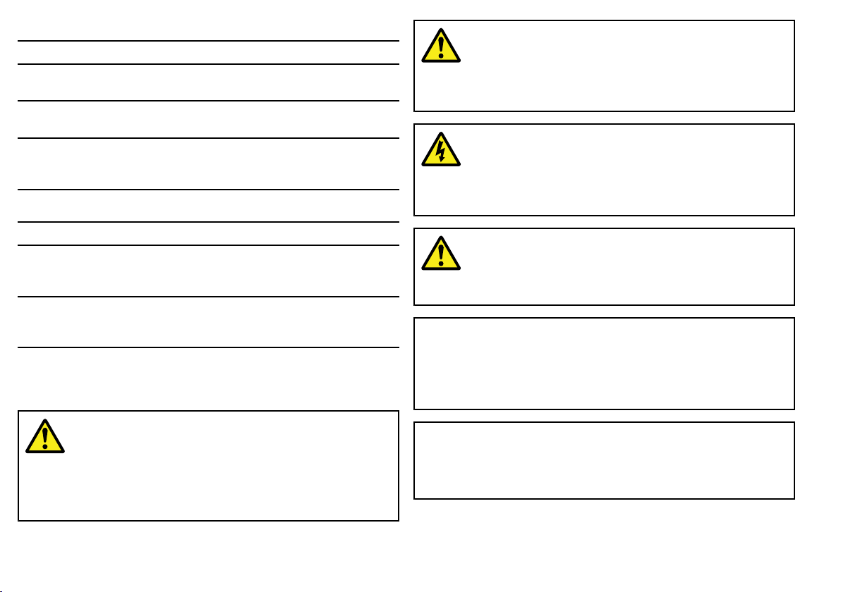
Warning:Potentialignitionsource
ThisproductisNOTapprovedforusein
hazardous/ammableatmospheres.DoNOTinstallin
ahazardous/ammableatmosphere(suchasinan
engineroomornearfueltanks).
Warning:Switchoffpowersupply
Ensuretheboat’spowersupplyisswitchedOFF
beforestartingtoinstallthisproduct.DoNOTconnect
ordisconnectequipmentwiththepowerswitchedon,
unlessinstructedinthisdocument.
Warning:Productgrounding
Beforeapplyingpowertothisproduct,ensureithas
beencorrectlygrounded,inaccordancewiththe
instructionsinthisguide.
Caution:Serviceandmaintenance
Thisproductcontainsnouserserviceable
components.Pleasereferallmaintenanceandrepair
toauthorizedRaymarinedealers.Unauthorizedrepair
mayaffectyourwarranty.
Warning:Productinstallationand
operation
Thisproductmustbeinstalledandoperatedin
accordancewiththeinstructionsprovided.Failureto
dosocouldresultinpersonalinjury ,damagetoyour
boatand/orpoorproductperformance.
8SPXSmartPilotinstallationinstructions
Caution:Powersupplyprotection
Wheninstallingthisproductensurethepowersource
isadequatelyprotectedbymeansofasuitably-rated
fuseorautomaticcircuitbreaker .
CertiedInstallation
RaymarinerecommendscertiedinstallationbyaRaymarine
approvedinstaller .Acertiedinstallationqualiesforenhanced
productwarrantybenets.ContactyourRaymarinedealerfor
furtherdetails,andrefertotheseparatewarrantydocumentpacked
withyourproduct.
EMCinstallationguidelines
Raymarineequipmentandaccessoriesconformtotheappropriate
ElectromagneticCompatibility(EMC)regulations,tominimize
electromagneticinterferencebetweenequipmentandminimizethe
effectsuchinterferencecouldhaveontheperformanceofyour
system
CorrectinstallationisrequiredtoensurethatEMCperformanceis
notcompromised.
ForoptimumEMCperformancewerecommendthatwherever
possible:
•Raymarineequipmentandcablesconnectedtoitare:
–Atleast1m(3ft)fromanyequipmenttransmittingorcables
carryingradiosignalse.g.VHFradios,cablesandantennas.
InthecaseofSSBradios,thedistanceshouldbeincreased
to7ft(2m).
–Morethan2m(7ft)fromthepathofaradarbeam.Aradar
beamcannormallybeassumedtospread20degreesabove
andbelowtheradiatingelement.
•Theproductissuppliedfromaseparatebatteryfromthatused
forenginestart.Thisisimportanttopreventerraticbehavior
anddatalosswhichcanoccuriftheenginestartdoesnothave
aseparatebattery.
•Raymarinespeciedcablesareused.
•Cablesarenotcutorextended,unlessdoingsoisdetailedin
theinstallationmanual.
Note:Whereconstraintsontheinstallationpreventanyof
theaboverecommendations,alwaysensurethemaximum
possibleseparationbetweendifferentitemsofelectrical
equipment,toprovidethebestconditionsforEMCperformance
throughouttheinstallation
Suppressionferrites
Raymarinecablesmaybettedwithsuppressionferrites.These
areimportantforcorrectEMCperformance.Ifaferritehastobe
removedforanypurpose(e.g.installationormaintenance),itmust
bereplacedintheoriginalpositionbeforetheproductisused.
Useonlyferritesofthecorrecttype,suppliedbyRaymarine
authorizeddealers.
Productdisposal
DisposeofthisproductinaccordancewiththeWEEEDirective.
TheWasteElectricalandElectronicEquipment(WEEE)
Directiverequirestherecyclingofwasteelectricalandelectronic
equipment.WhilsttheWEEEDirectivedoesnotapplytosome
Raymarineproducts,wesupportitspolicyandaskyoutobeaware
ofhowtodisposeofthisproduct.
Technicalaccuracy
Tothebestofourknowledge,theinformationinthisdocumentwas
correctatthetimeitwasproduced.However,Raymarinecannot
acceptliabilityforanyinaccuraciesoromissionsitmaycontain.In
addition,ourpolicyofcontinuousproductimprovementmaychange
specicationswithoutnotice.Asaresult,Raymarinecannotaccept
liabilityforanydifferencesbetweentheproductandthisdocument.
Introduction9

10SPXSmartPilotinstallationinstructions

Chapter2:Planningtheinstallation
Chaptercontents
•2.1Installationchecklistonpage12
•2.2Inboardautopilotsystemonpage12
•2.3SeaT alk
•2.4SeaT alkautopilotsystemonpage16
•2.5Partssuppliedonpage17
•2.6Requiredadditionalcomponentsonpage18
ng
autopilotsystemonpage14
Planningtheinstallation
11
2.1Installationchecklist
SMARTPILOT
3
4 5
1
2
D104 32-2
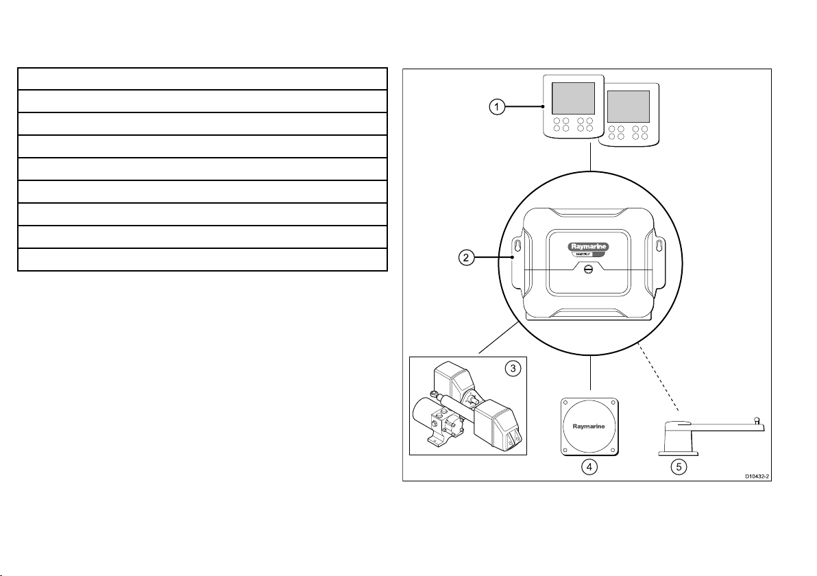
2.2Inboardautopilotsystem
Installationincludesthefollowingactivities:
InstallationTask
1Planyoursystem
2
3
Obtainallrequiredequipmentandtools
Siteallequipment
4Routeallcables.
5
Drillcableandmountingholes.
6Makeallconnectionsintoequipment.
7
Secureallequipmentinplace.
8Powerontestthesystem.
Schematicdiagram
Aschematicdiagramisanessentialpartofplanninganyinstallation.
Itisalsousefulforanyfutureadditionsormaintenanceofthe
system.Thediagramshouldinclude:
•Locationofallcomponents.
•Connectors,cabletypes,routesandlengths.
Atypicalinboardautopilotwillconsistoftheitemsshown:
1.Autopilotcontrolhead—Thisprovidesthedisplayand
controlsrequiredtousetheautopilot.Multiplecontrollerscanbe
addedifrequired,forexampleacontrollerateachhelmposition.
12
SPXSmartPilotinstallationinstructions

2.Coursecomputer—Thisisthecentralintelligencehubofthe
autopilotsystem,linkingthecontrolheadtothedriveunit.
3.Driveunit—Thedriveunitinterfaceswithyourboat’ssteering
system.
4.Fluxgatecompass—Theuxgatecompassprovidesthe
autopilotwithamagneticheadingrequiredformaintaininga
course.
5.Rudderreference—Requiredforsomesystemsonly .This
providesfeedbackfromtherudderandcanenhancesteering
performance.
Inadditiontheautopilotmayreceivedatafromothercomponents,
forexample:
•Multifunctiondisplay—Theautopilotcanconnecttoa
compatiblemultifunctiondisplay .Thisprovidesenhanced
capabilitiesforcreatingandfollowingroutes.
•GPS—Usuallyreceivedfromamultifunctiondisplay ,theautopilot
usespositiondatawhenfollowingroutesandcalculatingthe
optimumcoursetosteer .
•Windtransducer—Theautopilotcansteerrelativetoaspecied
windangle.
Planningtheinstallation
13
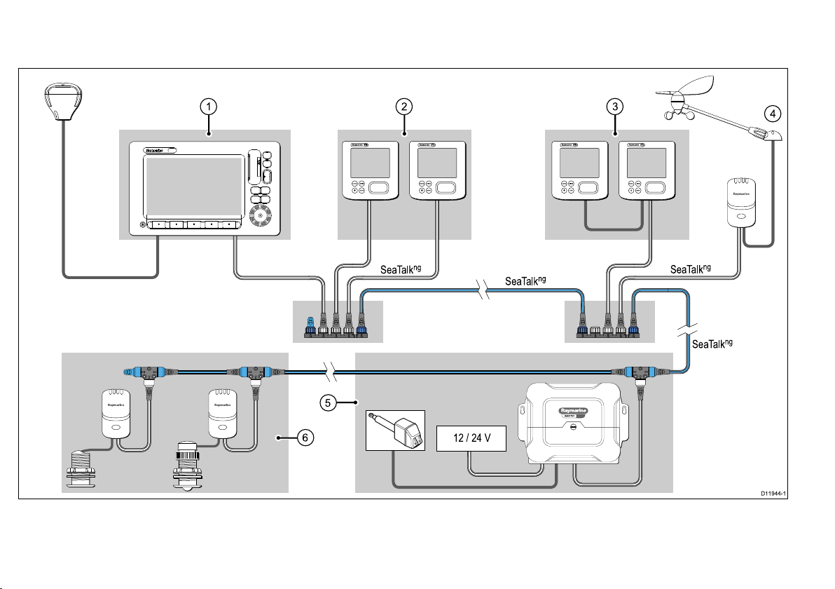
2.3SeaTalk
D119 44-1
ENTERCANCEL
MENU
SeaTalk
ng
SeaTalk
ng
SeaTalk
ng
SeaTalk
ng
12 / 24 V
1 2
ENTERCANCEL
MENU
ENTERCANCEL
MENU
ENTERCANCEL
MENU
3
4
5
6
SMARTPILOT
ng
autopilotsystem
TheautopilotmaybeconnectedaspartofawidernetworkofmarineelectronicsusingSeaTalk
ng
.
1.MultifunctiondisplaywithGPS.(GPSmaybeinternalorexternal)
2.Autopilotcontrollerandinstruments(e.g.helm1)
14
SPXSmartPilotinstallationinstructions

3.Autopilotcontrollerandinstruments(e.g.helm2)
4.Windtransducer
5.Autopilotcoursecomputeranddriveunit.ThismayalsosupplypowertotheSPXbackbone.
6.Speed/Depthtransducers.
Note:Themultifunctiondisplaywillrequireitsownpowerconnection.ItcannottakeitspowerfromtheSeaT alk
ng
backbone.
Seatalk
SeaTalk
ofcompatiblemarineinstrumentsandequipment.Itreplacesthe
olderSeaT alkandSeaT alk
SeaTalk
ng
ng
(NextGeneration)isanenhancedprotocolforconnection
2
protocols.
ng
utilizesasinglebackbonetowhichcompatible
instrumentsconnectusingaspur.Dataandpowerarecarriedwithin
thebackbone.Devicesthathavealowdrawcanbepoweredfrom
thenetwork,althoughhighcurrentequipmentwillneedtohavea
separatepowerconnection.
SeaTalk
CANbustechnology.CompatibleNMEA2000andSeaT alk/
SeaTalk
ng
isaproprietaryextensiontoNMEA2000andtheproven
2
devicescanalsobeconnectedusingtheappropriate
interfacesoradaptorcablesasrequired.
NMEA2000
NMEA2000offerssignicantimprovementsoverNMEA0183,most
notablyinspeedandconnectivity .Upto50unitscansimultaneously
transmitandreceiveonasinglephysicalbusatanyonetime,
witheachnodebeingphysicallyaddressable.Thestandard
wasspecicallyintendedtoallowforawholenetworkofmarine
electronicsfromanymanufacturertocommunicateonacommon
busviastandardizedmessagetypesandformats.
Planningtheinstallation
15
Loading...