


 Loading...
DSM25
Digital Sounder
Module
Owner’s Handbook
Document number: 81254-2
Date: March 2006
Trademarks and registered trademarks
Raymarine is a registered trademark of Raymarine plc.
All other product names are trademarks or registered trademarks of their respective owners.
Contents of this handbook © Raymarine 2006.

|
|
3 |
Contents |
|
|
Important Information ......................................................................................... |
7 |
|
Intended Use .................................................................................................. |
7 |
|
Safety Notices ............................................................................................... |
7 |
|
|
EMC Conformance ................................................................................. |
8 |
Product Disposal ............................................................................................. |
9 |
|
Conventions ................................................................................................. |
10 |
|
Technical Accuracy ........................................................................................ |
10 |
|
Warranty ....................................................................................................... |
10 |
|
Chapter 1: Overview .......................................................................................... |
11 |
|
1.1 |
Introduction ......................................................................................... |
11 |
1.2 |
What the Sounder Displays .................................................................. |
12 |
1.3 |
How the Fishfinder Works .................................................................... |
13 |
|
Interpreting the Bottom Structure ...................................................... |
13 |
|
How Targets are Displayed ................................................................... |
14 |
1.4 |
How to Use this Handbook ................................................................... |
15 |
Chapter 2: DSM25 Installation .......................................................................... |
17 |
|
2.1 |
Introduction ......................................................................................... |
17 |
|
Planning the Installation ...................................................................... |
17 |
2.2 |
Unpacking and Inspecting the Components ......................................... |
17 |
2.3 |
Optional Equipment ............................................................................. |
18 |
2.4 |
Selecting Sounder Module Mounting Location .................................... |
18 |
2.5 |
Mounting the Sounder Module ........................................................ |
19 |
2.6 |
Cable Runs ........................................................................................... |
21 |
2.7 |
System Connections ............................................................................. |
22 |
|
Display Connection .............................................................................. |
22 |
|
Transducer Connection ........................................................................ |
22 |
Chapter 3: Using the Sounder Module ............................................................. |
23 |
|
3.1 |
Introduction ......................................................................................... |
23 |
3.2 |
Selecting the Display Page .................................................................... |
24 |
|
Using the Course Deviation Indicator (CDI) .................................. |
27 |
|
Selecting a Split Window ............................................................. |
27 |
3.3 |
Adjusting the Display ........................................................................... |
28 |
|
Range Shift .................................................................................. |
28 |
|
Soft Key Selections ............................................................................... |
29 |
3.4 |
Fishfinder Settings .............................................................................. |
29 |
|
Gain Modes ....................................................................................... |
29 |
|
Auto Gain .................................................................................... |
30 |
|
Color Gain ...................................................................................... |
30 |
|
TVG (Time Variable Gain) ............................................................... |
30 |
|
Manually Adjusting the Gain Modes .............................................. |
30 |
4 |
|
DSM25 Owner’s Handbook |
|
|
|
|
Operating Frequency ............................................................................ |
31 |
|
Power Settings ...................................................................................... |
32 |
3.5 |
Zoom .................................................................................................... |
33 |
|
Adjusting the zoom ........................................................................ |
33 |
|
Adjusting the Position of the Zoomed Area .................................... |
34 |
3.6 |
Bottom Lock ......................................................................................... |
34 |
3.7 |
A-Scope ................................................................................................ |
36 |
3.8 |
Presentation ......................................................................................... |
37 |
|
White Line and Bottom Fill .................................................................... |
37 |
|
White Line ...................................................................................... |
37 |
|
Bottom Fill ...................................................................................... |
37 |
|
White Line and Bottom Fill together ............................................... |
38 |
|
Scroll Speed and Pause ......................................................................... |
38 |
|
SCROLL AUTO/MAN ..................................................................... |
38 |
|
SCROLL PAUSE/RESUME ............................................................. |
39 |
3.9 |
Determining Target Depths and Distance ........................................... |
39 |
3.10 |
Using Waypoints .................................................................................. |
40 |
Chapter 4: Fishfinder Setup .............................................................................. |
41 |
|
4.1 |
DSM Setup ............................................................................................ |
43 |
|
Depth Digit Size .................................................................................. |
43 |
|
Depth Lines ........................................................................................ |
43 |
|
Palette ................................................................................................ |
43 |
|
Depth Offset ....................................................................................... |
44 |
|
Speed Calibrate .................................................................................. |
44 |
|
Temp Calibrate ................................................................................... |
44 |
|
DSM Reset .......................................................................................... |
44 |
|
Trip Reset ............................................................................................ |
44 |
|
Interference Rejection (Int Rej) ........................................................... |
45 |
|
Second Echo Rejection ....................................................................... |
45 |
|
Max. Ping Rate ................................................................................... |
45 |
|
Ping Enable ........................................................................................ |
45 |
4.2 |
Fishfinder Alarms ................................................................................ |
46 |
|
Target Depth ID .................................................................................. |
46 |
|
Fish Alarm .......................................................................................... |
47 |
|
Fish Sensitivity .................................................................................... |
47 |
|
Shallow Alarm .................................................................................... |
47 |
|
Shallow Range ................................................................................... |
47 |
|
Deep Alarm ........................................................................................ |
47 |
|
Deep Range ........................................................................................ |
47 |
|
Temp. Alarm ....................................................................................... |
47 |
|
Temp. Range High .............................................................................. |
48 |
|
Temp. Range Low ............................................................................... |
48 |

|
|
5 |
Chapter 5: Maintenance and Problem Solving ............................................... |
49 |
|
5.1 |
Maintenance ........................................................................................ |
49 |
|
Routine Checks .................................................................................... |
49 |
|
Cleaning Instructions ........................................................................... |
49 |
|
EMC Servicing and Safety Guidelines ................................................... |
50 |
5.2 |
Resetting the Sounder .......................................................................... |
51 |
|
Power-on Reset .................................................................................... |
51 |
|
Factory Reset ........................................................................................ |
51 |
5.3 |
Problem Solving ................................................................................... |
52 |
|
Common Problems and Their Solutions ................................................ |
52 |
|
Status LED ............................................................................................ |
53 |
5.4 How to Contact Raymarine .................................................................. |
54 |
|
|
On the Internet ..................................................................................... |
54 |
|
In the US ............................................................................................... |
55 |
|
In Europe .............................................................................................. |
56 |
|
Worldwide Support .............................................................................. |
56 |
Appendix: Specifications .................................................................................. |
57 |
|
|
General ................................................................................................ |
57 |
|
Sounder Features ................................................................................. |
57 |
Index ................................................................................................................. |
|
59 |
6 |
DSM25 Owner’s Handbook |
|
|

7
Important Information
Intended Use
Raymarine DSM25 Digital Sounder Modules provide echo sounder data that can be displayed on A65 Multifunction Display units. DSM25s are intended for recreational depth finding and fish finding purposes.
Echo sounder systems require an appropriate Raymarine transducer unit and inter-connecting cable. Depending on the type of transducer connected, the DSM25 can also display temperature, distance traveled, and/or speed.
This manual contains important information for installing and operating your DSM25. To get the best results in operation and performance, please take the time to read this handbook thoroughly. Raymarine’s Technical Services representatives or your local dealer will be available to answer any questions you may have.
For full details on system integration, please refer to the handbook supplied with the A65 display.
Safety Notices
This equipment must be installed and operated in accordance with the instructions contained in this manual. Failure to do so can result in personal injury and/or navigational inaccuracies. In particular:
WARNING: Electrical Safety
The DSM25 contains high voltages. Adjustments require specialized service procedures and tools only available to qualified service technicians – there are no user serviceable parts or adjustments. The operator should never remove the cover or attempt to service the equipment.
Make sure the power supply is switched off before making any electrical connections.
WARNING: Transducer Cable
Removing the transducer cable from the rear of the sounder module while it is switched on can cause sparks. Only remove the transducer cable after power has been removed from the A65 display unit, which supplies power to the DSM. As with any electronic device, be sure the sounder module is mounted where it is well ventilated and free from gasoline fumes.
8 |
DSM25 Owner’s Handbook |
|
|
If the transducer cable is accidentally removed while the DSM25 is powered on, remove power from the sounder module, replace the transducer cable, and then return power to the module. As a safety feature, the DSM25 only recognizes that the transducer is connected at power-up.
CAUTION: Ultrasonic Energy
The transducer transmits high frequency energy while in use. The unit should be turned off when swimmers or divers are in close proximity to the transducer. (There is a lack of scientifically sound standards or guidelines for exposure levels and limits to ultrasound. This notice is precautionary only.)
EMC Conformance
All Raymarine equipment and accessories are designed to the best industry standards for use in the recreational marine environment.
Their design and manufacture conforms to the appropriate Electromagnetic Compatibility (EMC) standards, but correct installation is required to ensure that performance is not compromised. Although every effort has been taken to ensure that they will perform under all conditions, it is important to understand what factors could affect the operation of the product.
The guidelines given here describe the conditions for optimum EMC performance, but it is recognized that it may not be possible to meet all of these conditions in all situations. To ensure the best possible conditions for EMC performance within the constraints imposed by any location, always ensure the maximum separation possible between different items of electrical equipment.
For optimum EMC performance, it is recommended that wherever possible:
•Raymarine equipment and cables connected to it are:
•At least 5 ft (1.5 m) from any equipment transmitting or cables carrying radio signals, e.g., VHF radios, cables and antennas. In the case of SSB radios, the distance should be increased to 7 ft (2 m).
•More than 7 ft (2 m) from the path of a radar beam. A radar beam can normally be assumed to spread 20 degrees above and below the radiating element.
•The equipment is supplied from a separate battery from that used for engine start. Voltage drops below 10 V and starter motor transients can cause the equipment to reset.
This will not damage the equipment, but may cause the loss of some information and may change the operating mode.
Important Information |
9 |
|
|
•Raymarine specified cables are used. Cutting and rejoining these cables can compromise EMC performance and must be avoided unless doing so is detailed in the installation manual.
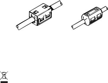
Suppression Ferrites
If a suppression ferrite is attached to a cable, this ferrite should not be removed. If the ferrite needs to be removed during installation it must be reassembled in the same position. If a ferrite is packed separately in the carton, it must be installed as soon as the cables are run.
The following illustration shows typical cable suppression ferrites sometimes used with Raymarine equipment. To ensure EMC compliance, always use these ferrites, if supplied by Raymarine for use with this equipment. If not supplied by Raymarine, a ferrite is not required for use with this equipment.
Connections to Other Equipment
If your Raymarine equipment is to be connected to other equipment using a cable not supplied by Raymarine, the suppression ferrite (if supplied) MUST always be attached to the cable nearest the Raymarine unit.
Product Disposal
When you want to dispose of this product at the end of its working life, please do so in accordance with local regulations.
10 |
DSM25 Owner’s Handbook |
|
|
Conventions
Throughout this handbook, the dedicated (labelled) keys are shown in bold capitals (for example, ENTER). The soft key functions, menu names and options are shown in normal capitals (for example, SCREEN).
Technical Accuracy
The technical and graphical information contained in this handbook, to the best of our knowledge, was correct as it went to press. However, the Raymarine policy of continuous improvement and updating may change product specifications without prior notice. As a result, unavoidable differences between the product and handbook may occur from time to time.
For the latest version of this or any Raymarine document in PDF format, please click the Owner’ Manuals link on the Customer Support page at www.raymarine.com.
Warranty
To register your DSM25 Digital Sounder Module ownership, please take a few minutes to fill out the warranty registration card found at the end of this handbook. It is very important that you complete the owner information and return the card to the factory in order to receive full warranty benefits.
11
Chapter 1: Overview
1.1 Introduction
This handbook describes how to install the DSM25 Digital Sounder Module and operate it using the A65 display unit. The DSM25 emits and receives sonar signals from a transducer mounted in the water, then interprets and transmits the data to the A65 installed on the console.
D7737-1
The DSM25 employs a very high transmission repetition or “ping” rate which, along with the digital adaptive high sample rate receiver, ensures that fish and bottom structure are presented in superb detail and optimal color allocation. The DSM25 digital bandwidth adaptation adjusts the receiver band width dynamically from very wide to very narrow, as required by the actual water conditions. This provides superior fish and bottom detection in all surroundings.
The DSM25 module is waterproof to IPX7 and can be installed either above or below deck.
The unit includes connections to:
•power and data via the A65
•the transducer
The DSM25 requires a transducer, mounted either thru-hull, in-hull, on the transom or on a trolling motor. Transducers can measure water depth, and if so equipped, temperature, distance traveled, and/or speed. It is important to position your transducer correctly.
12 |
DSM25 Owner’s Handbook |
|
|
1.2 What the Sounder Displays
When you first view the Fishfinder application on the A65, an image representing the echoes received by the DSM is displayed. As time passes this image scrolls from right to left and becomes a record of the data collected. The images at the right hand side of the display are therefore the most recent.
The Fishfinder window will display:
•The bottom together with any bottom structure such as reefs and shipwrecks
•Target images indicating fish
•The bottom depth
You can customize the sounder to:
•Display or hide the depth of the targets
•Display or hide the depth lines
•Change the color palette
•Change the zoom level
•Pause the scrolling image
•Display White Line or Bottom Fill features
•Enable a fish, shallow or deep water alarm
Frequency |
|
200 kHz |
0 |
|
|
|
|
|
|
34 |
36 |
20 |
|
|
||
|
|
|
|
|
|
||||||
|
|
|
|
|
|
||||||
|
|
|
|
|
|
|
|
|
|||
|
|
|
|
|
|
|
|
|
|||
|
|
|
|
|
|
|
|
|
|||
|
|
|
|
|
|
|
|
|
|
||
Target depth |
43 |
42 44 |
|
44 |
43 44 40 |
|
|
||||
|
|
||||||||||
|
|
||||||||||
|
|
|
47 |
|
47 |
|
|
|
|
||
Bottom depth |
|
43 9ft |
|
|
|
60 |
|
|
|||
|
|
|
|
|
|
||||||
|
|
|
|
|
|
||||||
|
|
FISHFINDER |
|
ZOOM |
BOTTOM |
|
A-SCOPE |
|
PRESENTATION |
|
|
|
|
SETTINGS |
|
LOCK |
|
|
|
||||
|
|
|
|
|
|
|
|
|
|
||
|
|
|
|
|
|
|
|
|
|
|
|
Bottom of transducer
Depth markers
Target images
Bottom
Range
D7910-1
Chapter 1: Overview |
13 |
|
|
1.3 How the Fishfinder Works
The Fishfinder application uses the DSM25 to process sonar signals from a suitable transducer and provide a detailed underwater view.
The transducer located on the bottom of the boat sends pulses of sound waves into the water and measures the time it takes for the sound wave to travel to the bottom and back. The returning sound echoes are affected by bottom structure and by any other objects in their path, such as fish, wrecks, or reefs.
The sounder module processes these echoes and sends data to the A65 which displays a visual interpretation of the underwater view. The strength of echoes is indicated on the display by different colors. You can use this information to determine the bottom structure, the size of fish and other objects in the water.
Notes: (1) The DSM can operate at a frequency of 50 kHz or 200 kHz.
(2)Some transducers will also enable the A65 to display water temperature and/or speed.
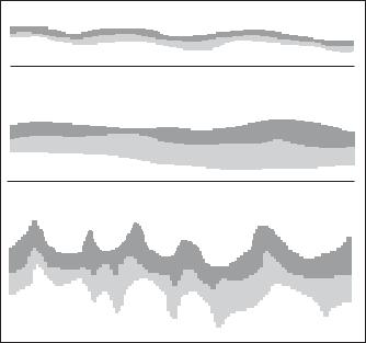
Interpreting the Bottom Structure
The bottom usually produces a strong echo. These images indicate the bottom conditions as follows:
A hard bottom (sand) produces a thin line
A soft bottom (mud or seaweed cover) produces a wide line. The dark layer indicates a strong signal.
-
A rocky or uneven bottom or a wreck produces an irregular image with peaks and troughs
D6855-1
14 |
DSM25 Owner’s Handbook |
|
|
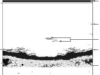
The dark layers indicate a good echo; the lighter areas weaker echoes. This could mean that the upper layer is soft and therefore allowing sound waves to pass to the more solid layer below.
It is also possible that the sound waves are making two complete trips – hitting the bottom, bouncing off the boat, then reflecting off the bottom again. This can happen if the water is shallow, the bottom is hard, or gain is set high.
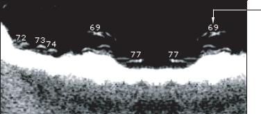
How Targets are Displayed
When a target is detected, it is displayed on screen as a mark. The shape and size of this mark is influenced by a combination of factors:
Boat speed
The shape of the target changes along with your speed. Slower speeds return flatter, more horizontal marks. As your boat’s speed increases, the target will tend to thicken and arch slightly until at fast speeds the mark resembles a double vertical line.
The depth of the target
The closer the target to the surface the larger the mark on screen.
Note: The depth of individual targets can be displayed by switching on the Target Depth ID in the Fishfinder Alarms Setup Menu.
The size of the target
The larger the target, the larger the return on the fishfinder display. The size of a fish target is however dependent upon the size of the fish’s swim bladder rather than its overall size. This swim bladder will vary in size between different breeds of fish.
The frequency of the transducer
The same target will appear differently when the transducer frequency is changed. The lower the frequency the broader the mark.
Chapter 1: Overview |
15 |
|
|
Target
Depth ID

 Target
Although weaker than the fish or bottom echoes, your fishfinder picture may be impaired by echoes received from floating or submerged debris, air bubbles or from your boat’s movements. This is known as background noise or clutter and is controlled by the gain modes (gain, color gain and TVG). Raymarine recommends that you enable your system to automatically control the ideal sensitivity level based on depth and water conditions. You can however adjust these settings manually if you prefer.
1.4 How to Use this Handbook
This handbook describes how to install and operate a DSM25 with your A65 display unit.
Chapter 2 provides planning considerations and detailed instructions for installing the DSM25 and connecting the sounder module to the display unit.
Chapter 3 shows how to operate the A65 display to view sonar echo data and details operating the A65’s controls in Fishfinder mode.
Chapter 4 provides instructions for setting up your DSM25 to suit your preferences.
Chapter 5 provides information on user maintenance and what to do if you experience problems.
The Appendix lists abbreviations used in this handbook.
The following figure displays the DSM25 as part of the A65 system:

16 |
DSM25 Owner’s Handbook |
|
|
RS12 GPS
DSM25
Power Supply |
A65 Display |
|
|
|
|
|
|
|
|
|
|
|
|
||||
|
|
|
|
|
|
|
|
|
|
|
|
|
|
||||
|
|
|
|
|
|
|
|
||||||||||
|
|
|
|
|
|
|
|
|
|
|
|
|
|
|
|
|
|
|
|
|
|
|
|
|
|
|
|
|
|
|
|
|
|
|
|
|
|
|
|
|
|
|
|
|
|
|
|
|
|
|
|
|
|
|
|
|
|
|
|
|
|
|
|
|
|
|
|
|
|
|
|
|
|
|
|
|
|
|
|
|
|
|
|
|
|
|
|
|
|
|
|
|
|
|
|
|
|
|
|
|
|
|
|
|
|
|
|
|
|
|
|
|
|
|
|
|
|
|
|
|
|
|
|
|
|
D7746-1 |
Transducer |
|
17
Chapter 2: DSM25 Installation
2.1 Introduction
This chapter provides details for mounting the DSM25 and connecting to the A65 display.
For the system to display depth, water temperature and speed, you must install the transducer type(s) capable of transmitting the appropriate data.
Planning the Installation
Before you install your system, plan the installation, considering:
•Correct transducer for your application
•Location of the sounder module, as described in Section 2.4
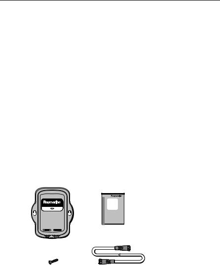
2.2Unpacking and Inspecting the Components
Unpack your system carefully, to prevent damage to the equipment. Save the carton and packing, in case you need to return the unit for service.
Check that you have all the correct system components:
DSM25
Owner's
Handbook
|
Owner’s Handbook, |
|
part no. 81254 |
Digital Sounder Module, |
|
part no. E63070 |
D7738-2 |
|
|
Mounting Screws, |
Power/Data Cable, 3.5m |
No.8 (x2) |
part no. R69086 |

18 |
DSM25 Owner’s Handbook |
|
|
2.3 Optional Equipment
If a longer connection is required from the DSM to the display, you can purchase one of the following A65 Network Cables from Raymarine. Be sure to install the suppression ferrites, if supplied.
Description |
Part No |
|
|
A65 Network Cable, 8.5m |
E36015 |
|
|
A65 Network Cable 15m |
E36016 |
|
|
2.4 Selecting Sounder Module Mounting Location
The DSM25 is waterproof to IPX-7 is and is designed to be mounted either above or below deck.
Mount the DSM25 where it is:
•protected from physical damage and excessive vibration
•protected from prolonged exposure to rain, salt spray and direct sunlight
•well ventilated
•as close to the transducer as possible
Do not locate the DSM25:
•in the engine compartment
•on the main console
When planning the installation, the following should be considered to ensure reliable and trouble free operation:
•Access: There must be sufficient space below the unit to enable cable connections to the panel connectors, avoiding tight bends in the cable.
•Interference: The selected location should be far enough away from devices that may cause interference, such as motors, generators, and radio transmitter/receivers. (See “EMC Conformance“ on page 8.)
•Magnetic compass: Mount the unit at least 3 ft (1 m) away from a magnetic compass.
•Cable runs: The unit must be located near the A65 display. The cable supplied is 11.5 ft (3.5 m) in length. Longer network cables are available as described in Section 2.3.
•Environment: Good ventilation is required to prevent the unit from overheating.

Chapter 2: DSM25 Installation |
19 |
|
|
•Status LED: Mount the unit where you can view the status LED on the front fascia. See page 53 for details.
Status LED 

D8722-1
CAUTION: Do Not Remove Transducer Cable when Powered On Removing the transducer cable from the DSM25 while power is turned on can cause sparks. As with any electronic device, be sure the sounder module is mounted where it is well ventilated and free from gasoline fumes.
2.5 Mounting the Sounder Module
The DSM25 can be mounted either above or below deck using the supplied hardware. To allow for ease of cable connection, mount the sounder module so that the cables hang below the unit.
The following figure displays dimensions for the DSM25. To mount the DSM25:
1.Hold the module in the location where you want to mount it, making sure it is perpendicular to the deck.
2.Mark the location of the two key holes onto the mounting surface.
Refer to the following figure.
Loading...