


 Loading...
Planning Guide Planning Guide Planning Guide Planning Guide
Quantum Scalarl i2000 Libraryi
2000i Scalar
6-00418-13 Rev A
Scalar i2000 Planning Guide, 6-00418-13 Rev A, August 2009, Made in USA.
Quantum Corporation provides this publication “as is” without warranty of any kind, either express or implied, including but not limited to the implied warranties of merchantability or fitness for a particular purpose. Quantum Corporation may revise this publication from time to time without notice.
COPYRIGHT STATEMENT
Copyright 2009 by Quantum Corporation. All rights reserved.
Your right to copy this manual is limited by copyright law. Making copies or adaptations without prior written authorization of Quantum Corporation is prohibited by law and constitutes a punishable violation of the law.
TRADEMARK STATEMENT
Quantum, ADIC, DLT, DLTtape, the Quantum logo, and the DLTtape logo are all registered trademarks of Quantum Corporation.
SDLT and Super DLTtape are trademarks of Quantum Corporation.
Other trademarks may be mentioned herein which belong to other companies.

Contents
Chapter 1 |
About This Guide and Your Product |
1 |
|
Product Safety Statements................................................................................ |
1 |
|
Product Model Number.................................................................................... |
2 |
|
Explanation of Symbols and Notes ................................................................. |
2 |
|
Other Documents You Might Need ................................................................ |
3 |
|
Getting More Information or Help.................................................................. |
4 |
Chapter 2 |
Description |
5 |
|
Control Module.................................................................................................. |
7 |
|
Expansion Modules ......................................................................................... |
19 |
|
I/O Management Unit .................................................................................... |
21 |
|
Host Attachment.............................................................................................. |
23 |
|
Remote Management ...................................................................................... |
23 |
|
Managing Your Remote Library.................................................................... |
24 |
|
Capacity on Demand....................................................................................... |
28 |
|
Encryption and Quantum’s Encryption Key Manager .............................. |
28 |
Scalar i2000 Planning Guide |
iii |

Chapter 3 |
System Specifications |
30 |
|
Performance Specifications............................................................................. |
30 |
|
Environmental Specifications......................................................................... |
31 |
|
Electrical Specifications................................................................................... |
31 |
|
Physical Specifications .................................................................................... |
35 |
|
Module Foot Pad Positions............................................................................. |
53 |
|
Module Floor Cutout....................................................................................... |
54 |
|
Scalar i2000 Seismic Bracing........................................................................... |
55 |
|
Drive Requirements and Compatibility ....................................................... |
55 |
|
Barcode Requirements .................................................................................... |
58 |
Chapter 4 |
Site Preparations |
60 |
|
General Information ........................................................................................ |
61 |
|
Physical Environment ..................................................................................... |
63 |
|
Access Conditions............................................................................................ |
64 |
|
Required Configuration Information............................................................ |
69 |
|
SAN Readiness ................................................................................................. |
71 |
|
Additional Comments..................................................................................... |
71 |
Scalar i2000 Planning Guide |
iv |
Chapter 1
About This Guide and Your
Product
This guide contains information necessary for site planning prior to the installation of the Scalar i2000. This guide is intended for anyone interested in learning about or anyone that needs to know how plan for the installation of the Scalar i2000.
Be sure to read all operating instructions in this
CAUTION manual and in the System, Safety, and Regulatory
Information Guide before operating this product.
This guide is intended to be used by system administrators, information technology professionals, and Quantum professional services and service personnel who will be involved with the installation of the library.
Product Safety Statements
This product is designed for data storage and retrieval using magnetic tape. Any other application is not considered the intended use. Quantum will not be held liable for damage arising from unauthorized use of the product. The user assumes all risk in this aspect.
This unit is engineered and manufactured to meet all safety and regulatory requirements. Be aware that improper use may result in
Scalar i2000 Planning Guide |
1 |

Chapter 1 About This Guide and Your Product
Product Model Number
bodily injury, damage to the equipment, or interference with other equipment.
BEFORE POWERING ON OR USING THIS
WARNING EQUIPMENT, READ THE SYSTEM, SAFETY,
AND REGULATORY INFORMATION GUIDE.
KEEP THE GUIDE FOR FUTURE REFERENCE.
Product Model Number
The Scalar i2000 model number is as follows: SCi2000
Explanation of Symbols and Notes
The following symbols appear throughout this document to highlight important information.
INDICATES A POTENTIALLY HAZARDOUS
WARNING SITUATION WHICH, IF NOT AVOIDED,
COULD RESULT IN DEATH OR BODILY
INJURY.
Indicates a situation that may cause possible CAUTION damage to equipment, loss of data, or
interference with other equipment.
Scalar i2000 Planning Guide |
2 |

Chapter 1 About This Guide and Your Product
Other Documents You Might Need
Note |
Indicates important information that helps you make |
|
better use of your system. |
||
|
Other Documents You Might Need
The following documents are also available for this product. These documents can be found on the product CD or at www.quantum.com/ support.
•Scalar i2000 User’s Guide (6-00421-xx)
•Quantum Intelligent Libraries Basic SNMP Reference (6-01159-xx)
•System, Safety, and Regulatory Information Guide (6-00618-xx)
Note |
Release Notes are also available for this product. The |
|
Release Notes describe changes to your system or |
||
|
||
|
firmware since the last release, provide compatibility |
|
|
information, and discuss any known issues and |
|
|
workarounds. The Release Notes can be found in the |
|
|
product box or at www.quantum.com/support. |
Scalar i2000 Planning Guide |
3 |

Chapter 1 About This Guide and Your Product
Getting More Information or Help
Getting More Information or Help
More information about this product is available on the Service and Support website at www.quantum.com/support. The Service and Support Website contains a collection of information, including answers to frequently asked questions (FAQs). You can also access software, firmware, and drivers through this site.
For further assistance, or if training is desired, contact Quantum:
Global Call Handling |
1-800-284-5101 |
For additional contact information: |
www.quantum.com/support |
To open a Service Request: |
www.quantum.com/esupport |
Scalar i2000 Planning Guide |
4 |

Chapter 2
Description
The Scalar i2000 library automates the retrieval, storage, and control of cartridges. The cartridges are mounted and retrieved from tape drives using a robotic assembly that is driven by application software from the host without operator intervention.
The library can be installed on a solid or a raised floor. The library has a standard 19-inch rack footprint and can be placed in a standard server rack space. Access is from the access and service doors so the library can be placed with either side against a wall, or between racks.
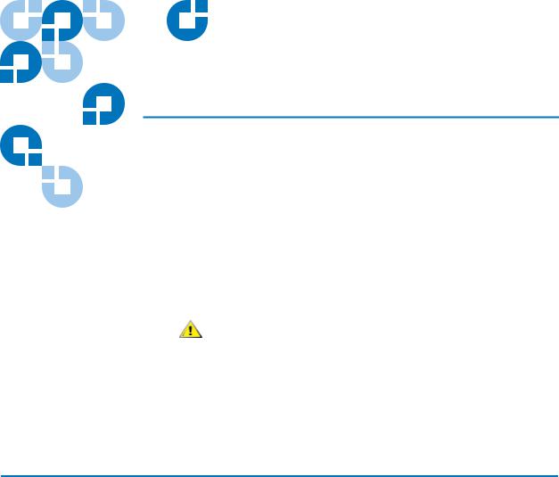
The library is designed for ease of installation, configuration, and field upgrades. The minimum library configuration consists of one control module. Up to seven expansion modules can be added to the control module as storage and tape drive requirements change. The maximum library can be configured to accommodate from 102 through 3,492 LTO or from 100 through 2,915 SDLT cartridges, from 1 through 96 tape drives, and from 1 through 8 Import/Export (I/E) stations. See figure 1 on page 6.
This chapter provides a description of the following features and components:
•Control Module on page 7
•Expansion Modules on page 19
•I/O Management Unit on page 21
•Host Attachment on page 23
•Remote Management on page 23
Scalar i2000 Planning Guide |
5 |
Chapter 2 Description
•Managing Your Remote Library on page 24
•Capacity on Demand on page 28
•Magazine and Drive Location in the Control Module on page 16
Figure 1 Front View of a
Control Module and Expansion
Module
|
|
expansion module |
|
|
operator panel |
|
|
|
control module |
|
touch screen |
I/E station 
 access doors
Scalar i2000 Planning Guide |
6 |
Chapter 2 Description
Control Module
Control Module
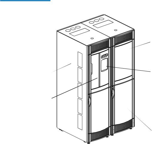
The control module contains the following components, as shown in figure 2 on page 8.
•Library Management Module on page 8
•Import/Export Station on page 10
•Cartridges on page 10
•Tape Drives on page 12
•Cartridge Magazines on page 15
•Operator Panel on page 17
•Power System on page 19
Scalar i2000 Planning Guide |
7 |
Chapter 2 Description
Control Module
Figure 2 Front and Back View |
|
of the Control Module |
|
front view |
back view |
|
magazines |
I/O |
|
and |
||
management |
||
cartridge |
||
unit |
||
slots |
||
|
||
I/E |
|
|
station |
|
|
drive |
library |
|
management |
||
clusters |
module |
power supplies
picker
Library Management
Module
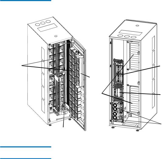
The library management module controls system hardware and enables external devices to perform configuration and obtain system status. The library management module contains the following boards:
•Management control blade (MCB) - Manages the library, passing commands to and from the robotics control unit as well as the storage area network (SAN) components.
•Robotics control unit (RCU) - Controls the picker and accessor functionality.
•Library motor drive (LMD) - Distributes power to the picker along with the X and Y-axis circuits. It also distributes power to the touch screen.
Scalar i2000 Planning Guide |
8 |
Chapter 2 Description
Control Module
Figure 3 Library Management
Module Boards
management control blade
robotics control unit
library motor drive
|
The cartridge accessor moves cartridges between storage cells, tape |
|
Cartridge Accessor |
||
drives, and the I/E station. A picker is used to get or put cartridges in a |
||
|
||
|
storage cell or a tape drive slot. The picker moves along an X and Y axis |
|
|
and can pivot 180o. A barcode scanner on the picker assembly identifies |
|
|
cartridges located in storage cells. |
Scalar i2000 Planning Guide |
9 |

Import/Export Station
Cartridges
Chapter 2 Description
Control Module
I/E stations enable you to import and export cartridges without interrupting normal library operation. The I/E station is installed on the front of the control module or any of the seven expansion modules. See figure 1 on page 6 and figure 2 on page 8 to see the location of the I/E station.
Each I/E station has a capacity of 24 LTO or 20 SDLT cartridges that are located in four removable magazines.
Note |
The I/E station cannot be configured as a |
|
storage location, but can be part of a a logical |
||
|
||
|
division of library resources known as |
|
|
partitions. |
Cartridges are stored in magazines within the library and identified by an operator-attached, machine-readable barcode label. The library supports barcode labels with 14 characters plus a oneor two-character media identifier depending on drive type, LTO or SDLT. The library currently supports Code 39 (3 of 9) type barcode labels.
Scalar i2000 Planning Guide |
10 |

Chapter 2 Description
Control Module
Figure 4 Example of LTO
Cartridge Insertion into a
Magazine
magazine barcode
LTO cartridge
 LTO magazine
cartridge barcode location
|
See Mixed Media Support and Rules on page 13 for details about the use |
||
|
of drives and cartridges. See Barcode Requirements on page 58 for |
||
|
additional specification information. |
||
|
The Scalar i2000 library supports WORM (write once, read many) |
||
WORM Support |
|||
technology in LTO-3 and LTO-4 tape drives. WORM requirements |
|||
|
|||
|
include: |
||
|
• |
Cartridges |
|
|
• |
Firmware |
|
• WORM-supported LTO-3 tape drives
• WORM-supported LTO-4 tape drives
WORM allows non-erasable data to be written once and provides extra data security by prohibiting accidental data erasure. When the library firmware and WORM-supported LTO-3 and LTO- 4 tape drive code are installed on a library with LTO-3 and LTO-4 tape drives, the WORM feature is supported whenever the operator uses WORM cartridges.
Scalar i2000 Planning Guide |
11 |

Chapter 2 Description
Control Module
|
The tape drives are enclosed in a universal drive sled. You can hot swap |
||
Tape Drives |
|||
and hot add all types of drives. The library supports the following tape |
|||
|
|||
|
drives types: |
|
|
|
• IBM LTO-1 or LTO-2 LVD–SCSI |
||
|
• IBM LTO-1, LTO-2, LTO-3, or LTO-4 FC Multi-mode |
||
|
• HP LTO-3 and HP LTO-4 FC Multi-mode |
||
|
• Quantum SDLT-320 LVD–SCSI |
||
|
• Quantum SDLT-600 FC |
||
|
• Quantum DLT-S4 FC |
||
|
Quantum’s Scalar i2000 library supports LTO-4 tape media encryption |
||
|
using the IBM LTO-4 Fibre Channel drives only. All IBM LTO-4 FC drives |
||
|
are encryption-capable, but to use the Q-EKM software application, you |
||
|
must purchase a Q-EKM license and provide a server or servers on which |
||
|
to install Q-EKM. Q-EKM does not currently support encryption on other |
||
|
tape drive types or manufacturer brands, even if they are assigned to a |
||
|
partition selected for encryption. For more information, see Encryption |
||
|
and Quantum’s Encryption Key Manager on page 28. |
||
|
The control module and expansion modules have upper and lower drive |
||
|
clusters. Each library must have at least one tape drive. Each drive cluster |
||
|
can house up to six tape drives for a total of 12 drives. Additional drives |
||
|
can be added to each of the expansion modules in the configuration. This |
||
|
enables you to have a total of 96 drives. |
||
|
Note |
The term drive cluster defines a grouping of up |
|
|
to six tape drives below or above the middle |
||
|
|
||
|
|
X-axis rail. See figure 2 on page 8 for the |
|
|
|
locations of drive clusters. |
|
|
The drives must be installed in the bottom-to-top order in the control |
||
|
module before any are added to the first expansion module. See figure 6 |
||
|
on page 16 for details about the use of drives and cartridges. Refer to |
||
|
Drive Requirements and Compatibility on page 55 for LTO and SDLT |
||
|
drive requirements. |
||
|
Note |
When you add drives, you lose storage slots. |
|
|
|
||
Scalar i2000 Planning Guide |
12 |

Mixed Media Support and
Rules
Chapter 2 Description
Control Module
The library supports both LTO and SDLT cartridges and drives in the same configuration, providing you adhere to the following rules:
•When purchasing a library with mixed media, the new orders must specify the base system technology (either LTO or SDLT) and the number of magazines, the number of drives, and the number of I/E magazines for each media type they need. The base system is considered the primary media type used in the library.
•Multiple media can be mixed at the magazine level.
•The supported multiple media are LTO-1, LTO-2, LTO-3, LTO-3 WORM, LTO-4, LTO-4 WORM, SDLT-320, SDLT-600, and DLT-S4.
•If you are loading cartridges into the library via the I/E station, you must have a magazine of each of the two types of media in the I/E station (LTO and SDLT).
•Mixed media can be within the 100 slot capacity increment, with the following restrictions:
•SDLT must be ordered in multiples of five because the magazines hold five cartridges.
•LTO must be ordered in multiples of six because the magazines hold six cartridges.
•Regardless of the mixed quantities of each media type, the total slots licensed will still be in multiples of 100.
•Field upgrades of the library to existing single media systems must specify a mixed media picker kit, if mixed media will be used in the upgraded library.
•Drive types can be installed in any order. For example, an LTO drive can occupy the first drive position, an SDLT drive can occupy the second, and another LTO can occupy the third drive position.
•However, drives must be installed starting in the lower most drive slot of the control module. Once the control module has 12 drives installed from bottom to top, you must move to bottom drive position of the first expansion module.
•The library must include at least one drive for each type of cartridge used.
Scalar i2000 Planning Guide |
13 |

Chapter 2 Description
Control Module
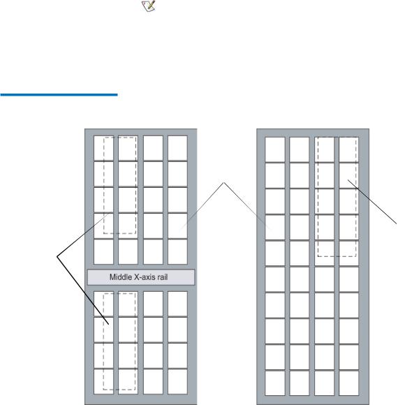
•Magazines must be installed in the control module starting with back rack (drive side). Once the back rack (drive side) is full, you must then install magazines in the door side, starting with the top left corner. See figure 5 on page 14.
•The secondary media type is installed beginning at storage slot 4,096 or the first media magazine. See figure 5 on page 14.
Figure 5 Magazine Installation
Order
tape drives
magazines must  be installed from bottom to top
X-axis rail
tape drives
drive side |
door side |
Scalar i2000 Planning Guide |
14 |

Cartridge Magazines
Table 1 Cartridge Capacities
in Library Modules
Chapter 2 Description
Control Module
The cartridge magazine is a storage assembly that installs on the drive side or door side of the control module or expansion module. It contains the cartridge slots and provides flexibility when adding storage cartridges to a module. There are two types of magazines, one for SDLT and another for LTO. Because the two magazines are the same size they can be mixed in the library. The SDLT magazines hold five cartridges and the LTO magazines hold six cartridges.
|
Cartridges |
Magazines |
Magazines per |
Control Module |
Expansion |
Type of |
per |
per Control |
Expansion |
Cartridge |
Module Cartridge |
Cartridge |
Magazine |
Modulea |
Moduleb |
Capacityc |
Capacityd |
SDLT |
5 |
44 min/51 |
50 min/76 max |
220 min/255 max |
250 min/380 max |
|
|
max |
|
|
|
|
|
|
|
|
|
LTO |
6 |
44 min/51 |
50 min/76 max |
264 min/306 max |
300 min/456 max |
|
|
max |
|
|
|
|
|
|
|
|
|
a.The minimum is based on having 11 additional drives installed. The maximum is based on having one drive and one I/E station installed.
b.The minimum is based on having an I/E station and 12 drives installed. The maximum is based on having no drives or an I/E station installed.
c.The minimum is based on having 11 additional drives installed. The maximum is based on having one drive and one I/E station installed.
d. The minimum is based on having an I/E station and 12 drives installed. The maximum is based on having no drives or an
I/E station installed.
Each magazine has a barcode label that the scanner reads for identification and inventory. An optional, snap-on dust cover is available for the magazines. The magazines with the dust cover have interlocked stacking that enables easier storage of the media when they are removed from the library for external storage.
Scalar i2000 Planning Guide |
15 |

Chapter 2 Description
Control Module
Figure 6 Magazine and Drive
Location in the Control Module
I/E cartridge station magazines
drives or storage
drive side |
door side |
Scalar i2000 Planning Guide |
16 |
Operator Panel
Chapter 2 Description
Control Module
The operator panel is located on the front of the control module and consists of indicators and a touch screen (see figure 7). The buttons are for library control and power while the indicators provide library status.
Figure 7 Operator Panel
Status indicator
Power indicator/button
Robotics Enabled indicator/button 
touch screen
The touch screen is the library navigation point and provides access to the Library Management Console (LMC), which is shown in figure 8 on page 18. The LMC consists of five primary areas:
•Title bar–provides the library name
•Menu bar–provides menu access to all library management commands
•Tool bar–provides quick access to the most commonly executed functions
•Library information panel–provides real-time library information
•Overall system status–provides real-time status information for the six subsystems of the physical library
Scalar i2000 Planning Guide |
17 |

Figure 8 LMC
title bar menu bar
tool bar
current library
current activity
data transfer statistics
data mount statistics
system status buttons
Chapter 2 Description
Control Module
current time and date
media slot usage
configuration summary
For additional information on the touch screen and the LMC, refer to the
Scalar i2000 User’s Guide.
Scalar i2000 Planning Guide |
18 |

Chapter 2 Description
Expansion Modules
|
The library supports single and redundant power configurations. The |
||
Power System |
|||
single configuration has a single AC line input and single DC power |
|||
|
|||
|
supply. The redundant configuration has dual AC line input and dual DC |
||
|
power supplies. You can hot swap a power supply if you have a |
||
|
redundant power supply. You can hot add a second power supply. |
||
|
The power system consists of the following: |
||
|
• |
Power supply |
|
|
• |
Power distribution unit |
|
|
• |
AC power cord |
|
A single power switch, located on the front door, turns on and off all power for the control module and attached expansion modules. Each power distribution unit has a second circuit breaker, located in the rear of the module, that controls the module power supply output. The power supply has three LEDs that provide status information. The power system also has four fuses for system protection.
Expansion Modules
Expansion modules enable the library to expand by adding space for tape drives, an I/E station, and cartridges. Each expansion module adds from 300 through 456 LTO or from 250 through 380 SDLT cartridge slots depending on the number of tape drives installed and whether an I/E station is installed. See figure 9 on page 20 for location information. The library’s maximum configuration includes up to seven expansion modules for a total of eight modules. Expansion modules can be added only to the right of the control module.
The expansion modules can accommodate the following functional units:
•I/O management unit
•Tape drives
•Cartridge storage
•I/E station (optional)
•AC power compartment (required only if drives are added)
Scalar i2000 Planning Guide |
19 |
Chapter 2 Description
Expansion Modules
If an expansion module contains only cartridges, all power is derived from the control module.
Note |
To ensure ethernet communication, control |
|
management blades (CMB) must be installed |
||
|
||
|
in each expansion module of a multi-module |
|
|
configuration. If the last expansion module |
|
|
does not contain FC I/O blades, a CMB is not |
|
|
necessary. |
Figure 9 Magazine and Drive
Location in the Expansion
Module
cartridge magazines
I/E station (optional)
drive cluster (optional)
drive side |
door side |
Scalar i2000 Planning Guide |
20 |
Loading...