


 Loading...
SDLT 600A Tape Drive
Quick Start Guide
CONTENTS |
|
Identifying the Proper Tape Drive |
|
Installation Procedure ............................. |
1 |
Checking the Tabletop Tape Drive .......... |
2 |
Connecting the Tabletop Tape Drive ...... |
2 |
Checking the Rackmount Tape Drive...... |
3 |
Connecting the Rackmount Tape Drive ..3 Configuring the SDLT 600A Tape Drive...4
Changing Passwords ............................... |
6 |
Formatting Media Cartridges ................. |
7 |
Using the FTP Client................................. |
7 |
Drag and Drop Files ................................. |
8 |
This quick start guide provides basic installation and configuration instructions. For more information, see the SDLT 600A Product Manual on the product documentation CD-ROM provided with your tape drive.
1Inspect the shipping box and contents of the box for damage.
If you find any damage, report it to the shipping company or contact Quantum immediately.
2Verify that the Ethernet cables are compatible with the connectors on the host computer.
For more information on this or other Quantum products, see the documents on the product documentation CD-ROM or visit www.quantum.com.
Identifying the Proper Tape Drive Installation
Procedure
For immediate help installing the tape drive, contact Quantum Technical Support at 1-888-827-3378.
For detailed information about compatibility, see the SDLT 600A Product Manual 81-81487-xx.
The SDLT 600A is available in two configurations, tabletop and rackmount. Follow the installation procedures appropriate to your tape drive.
SDLT 600A Tape Drive Quick Start Guide
Checking the Tabletop Tape Drive
To check that the tabletop tape drive works and is not damaged:
1Connect one end of the power cord to the tape drive power cord connector and plug the other end of the power cord into an AC outlet.
2Power on the tape drive using the switch on the rear panel (see figure 1).
Figure 1 Check the Tabletop
Tape Drive
Power cord connector
On/off switch
The tape drive performs a self-diagnostic test, called a PowerOn Self-Test (POST), each time you power it on. During POST, each LED lights in sequence. When POST has completed successfully, the middle LED stops flashing and remains illuminated and the left and right LEDs remain off.
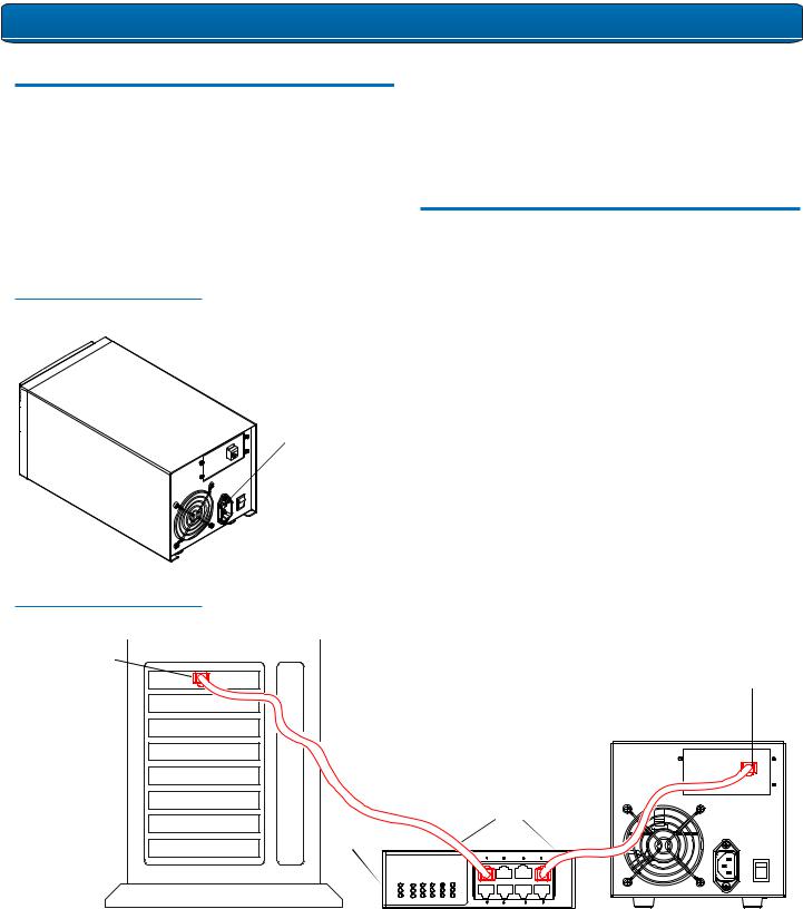
Connecting the Tabletop Tape Drive
Connect the tabletop tape drive to the host computer though the network port:
1Connect one end of the Ethernet cable to the network port located on the rear of the tape drive.
2Connect the other end to a network switch or router (see figure 2).
3Proceed to Configuring the SDLT 600A Tape Drive.
Figure 2 Connect to the Network
Port
Host network port |
Note: |
|
|
Network port |
|
|
The GigE network port is backward compatible with |
|
|
|
|
|
100BaseT and 10BaseT networks. To get the full |
|
|
performance of the drive, use gigabit Ethernet networks. |
|
|
Optionally, the tape drive may be |
|
|
directly connected to the host |
|
|
network port. |
|
|
Ethernet cables |
|
Router
2

SDLT 600A Tape Drive Quick Start Guide
Checking the Rackmount Tape Drive
To check that the rackmount tape drive works and is not damaged:
1Connect one end of the power cord to the tape drive power cord connector and plug the other end of the power cord into an AC outlet.
2Power on the tape drive using the switch on the front panel (see figure 3).
Figure 3 Check the
Rackmount Tape Drive
On/off switch
Power cord connector
Figure 4 Install the
Rackmount Tape Drive
Thumbscrews
 Power button
2Secure the unit to the rack with the thumbscrews.
3Connect the power cable to the rear of the rackmount SDLT 600A tape drive (see figure 5).
Figure 5 Connect the Power
and Network Cables
The tape drive performs a self-diagnostic test, called a PowerOn Self-Test (POST), each time you power it on. During POST, each LED lights in sequence. When POST has completed successfully, the middle LED stops flashing and remains illuminated and the left and right LEDs remain off.
Disconnect the power cord from the power cord connector.
Power cord connector
Connecting the Rackmount Tape Drive
Install the rackmount tape drive in a rack and then connect the drive to a network though the network (GigE) port located on
the rear of the drive:
1 Slide the rackmount tape drive into the equipment rack (see figure 4).
Network port
To router or switch
4 Connect one end of the Ethernet cable to the network port located on the rear of the SDLT 600A tape drive and connect the other end to a network switch or router.
5 Power on the tape drive using the switch on the front panel.
6 Proceed to Configuring the SDLT 600A Tape Drive.
3
Loading...