


 Loading...
User’s Guide User’s Guide User’s Guide User’s Guide User’s Guide User’s Guide
LTO-5 Tape Drive
5-LTO
6-66786-01 Rev. A
LTO-5 Tape Drive User’s Guide, PN 6-66786-01 Rev. A, March 2009. Product of U.S.A.
Quantum Corporation provides this publication “as is” without warranty of any kind, either express or implied, including but not limited to the implied warranties of merchantability or fitness for a particular purpose. Quantum Corporation may revise this publication from time to time without notice.
COPYRIGHT STATEMENT
Copyright 2009 by Quantum Corporation. All rights reserved.
Your right to copy this manual is limited by copyright law. Making copies or adaptations without prior written authorization of Quantum Corporation is prohibited by law and constitutes a punishable violation of the law.
TRADEMARK STATEMENT
Quantum and the Quantum logo are registered trademarks of Quantum Corporation. Other trademarks may be mentioned herein which belong to other companies.

Contents
Preface |
|
xi |
Chapter 1 |
Introduction |
1 |
|
Overview . . . . . . . . . . . . . . . . . . . . . . . . . . . . . . . . . . . . . . . . . . . . . . . |
. 1 |
|
Drive Models . . . . . . . . . . . . . . . . . . . . . . . . . . . . . . . . . . . . . . . . . . . . |
. 2 |
|
Internal . . . . . . . . . . . . . . . . . . . . . . . . . . . . . . . . . . . . . . . . . . |
. 2 |
|
Tabletop . . . . . . . . . . . . . . . . . . . . . . . . . . . . . . . . . . . . . . . . . |
. 2 |
|
Features. . . . . . . . . . . . . . . . . . . . . . . . . . . . . . . . . . . . . . . . . . . . . . . . |
. 3 |
Chapter 2 |
Installation Procedures |
5 |
|
Before Installing the LTO-5 Tape Drive . . . . . . . . . . . . . . . . . . . . . . . . |
. 6 |
|
Handling Precautions and Installation Guidelines . . . . . . . . . . |
. 6 |
|
Preinstallation Requirements. . . . . . . . . . . . . . . . . . . . . . . . . . |
. 7 |
|
Unpacking and Inspecting the Drive. . . . . . . . . . . . . . . . . . . . |
. 7 |
|
Installing the Internal LTO-5 Tape Drive . . . . . . . . . . . . . . . . . . . . . . . . |
. 8 |
|
Installing the Internal LTO-5 Half-Height Tape Drive . . . . . . . . |
. 8 |
|
Installing the Internal LTO-5 Full-Height Tape Drive . . . . . . . . |
12 |
|
Installing the Tabletop LTO-5 Tape Drive . . . . . . . . . . . . . . . . . . . . . . . |
15 |
|
Installing the Tabletop LTO-5 Half-Height Tape Drive . . . . . . . |
15 |
|
Installing the Tabletop LTO-5 Full-Height Tape Drive. . . . . . . . |
17 |
LTO-5 Tape Drive User’s Guide |
iii |
Contents
|
Installing the LTO Driver Software . . . . . . . . . . . . . . . . . . . . . . . . . . . . |
19 |
|
|
|
|
|
|
Chapter 3 |
Operation |
21 |
|
Understanding the Front Panel Display . . . . . . . . . . . . . . . . . . . . . . . . |
21 |
|
Using LTO Tape Cartridges . . . . . . . . . . . . . . . . . . . . . . . . . . . . . . . . . |
28 |
|
Loading a Tape Cartridge . . . . . . . . . . . . . . . . . . . . . . . . . . . . |
28 |
|
Unloading a Tape Cartridge . . . . . . . . . . . . . . . . . . . . . . . . . . |
28 |
|
Write Protecting a Tape Cartridge. . . . . . . . . . . . . . . . . . . . . . |
29 |
|
Tape Cartridge Care and Maintenance . . . . . . . . . . . . . . . . . . |
30 |
|
Data Cartridges . . . . . . . . . . . . . . . . . . . . . . . . . . . . . . . . . . . . . . . . . . |
31 |
|
WORM Data Cartridges . . . . . . . . . . . . . . . . . . . . . . . . . . . . . . . . . . . . |
32 |
|
LTO-5 Tape Drives and Partitioning . . . . . . . . . . . . . . . . . . . . . . . . . . . |
32 |
|
LTO-5 Tape Drives and Encryption . . . . . . . . . . . . . . . . . . . . . . . . . . . . |
32 |
|
When should I use encryption?. . . . . . . . . . . . . . . . . . . . . . . . |
33 |
|
How do I enable encryption? . . . . . . . . . . . . . . . . . . . . . . . . . |
33 |
|
When will I be asked to enter the key? . . . . . . . . . . . . . . . . . . |
33 |
|
What happens if I don't remember the key? . . . . . . . . . . . . . . |
34 |
|
Does encryption affect tape drive performance? . . . . . . . . . . |
34 |
|
Does the tape drive encrypt media in an earlier Ultrium format? |
|
|
34 |
|
|
Cleaning the Tape Drive. . . . . . . . . . . . . . . . . . . . . . . . . . . . . . . . . . . . |
34 |
|
Performing an Emergency Cartridge Eject . . . . . . . . . . . . . . . . . . . . . . |
36 |
|
|
|
|
|
|
Chapter 4 |
Theory |
37 |
|
Track Layout . . . . . . . . . . . . . . . . . . . . . . . . . . . . . . . . . . . . . . . . . . . . |
37 |
|
Recording Method. . . . . . . . . . . . . . . . . . . . . . . . . . . . . . . . . . . . . . . . |
38 |
|
Data Buffer . . . . . . . . . . . . . . . . . . . . . . . . . . . . . . . . . . . . . . . . . . . . . |
39 |
|
Data Integrity . . . . . . . . . . . . . . . . . . . . . . . . . . . . . . . . . . . . . . . . . . . |
39 |
|
Error-correction Code (ECC) . . . . . . . . . . . . . . . . . . . . . . . . . . |
39 |
|
Servo-tracking Faults. . . . . . . . . . . . . . . . . . . . . . . . . . . . . . . . |
41 |
|
Data Compression . . . . . . . . . . . . . . . . . . . . . . . . . . . . . . . . . . . . . . . . |
41 |
|
Data Compression Considerations . . . . . . . . . . . . . . . . . . . . . |
42 |
|
Intelligent Data Compression . . . . . . . . . . . . . . . . . . . . . . . . . |
43 |
iv |
LTO-5 Tape Drive User’s Guide |

Contents
Chapter 5 |
Specifications |
45 |
|
Physical Specifications . . . . . . . . . . . . . . . . . . . . . . . . . . . . . . . . . . . . . |
45 |
|
Power Specifications . . . . . . . . . . . . . . . . . . . . . . . . . . . . . . . . . . . . . . |
50 |
|
Drive Performance Specifications. . . . . . . . . . . . . . . . . . . . . . . . . . . . . |
50 |
|
Environmental Requirements. . . . . . . . . . . . . . . . . . . . . . . . . . . . . . . . |
52 |
|
Injected Noise Specifications . . . . . . . . . . . . . . . . . . . . . . . . . . . . . . . . |
53 |
|
Reliability Specifications . . . . . . . . . . . . . . . . . . . . . . . . . . . . . . . . . . . |
53 |
|
Mean Time Between Failures. . . . . . . . . . . . . . . . . . . . . . . . . . |
54 |
|
Mean Time to Replace. . . . . . . . . . . . . . . . . . . . . . . . . . . . . . . |
54 |
|
LTO Cartridge Specifications . . . . . . . . . . . . . . . . . . . . . . . . . . . . . . . . |
55 |
|
Environmental Considerations . . . . . . . . . . . . . . . . . . . . . . . . |
55 |
|
Cartridge Memory. . . . . . . . . . . . . . . . . . . . . . . . . . . . . . . . . . |
55 |
|
Cartridge Reliability. . . . . . . . . . . . . . . . . . . . . . . . . . . . . . . . . |
56 |
Chapter 6 |
Troubleshooting Guide |
57 |
|
Installation Best Practices . . . . . . . . . . . . . . . . . . . . . . . . . . . . . . . . . . |
57 |
|
Following SCSI Best Practices . . . . . . . . . . . . . . . . . . . . . . . . . |
57 |
|
Using a Serial-attached SCSI Host Bus Adapter . . . . . . . . . . . . |
57 |
|
HBA Preinstallation Checks . . . . . . . . . . . . . . . . . . . . . . . . . . . |
58 |
|
Troubleshooting Suggestions . . . . . . . . . . . . . . . . . . . . . . . . . . . . . . . |
58 |
|
Understanding LED Sequences . . . . . . . . . . . . . . . . . . . . . . . . . . . . . . |
62 |
|
Encryption LED, LTO-5 Tape Drive . . . . . . . . . . . . . . . . . . . . . . |
69 |
|
Problems with cartridges. . . . . . . . . . . . . . . . . . . . . . . . . . . . . . . . . . . |
70 |
|
The cartridge is jammed . . . . . . . . . . . . . . . . . . . . . . . . . . . . . |
70 |
|
Encryption Troubleshooting . . . . . . . . . . . . . . . . . . . . . . . . . . . . . . . . |
72 |
Appendix A |
Installation Checklists |
73 |
|
Internal LTO-5 Tape Drive Quick Start . . . . . . . . . . . . . . . . . . . . . . . . . |
73 |
|
Tabletop LTO-5 Tape Drive Quick Start . . . . . . . . . . . . . . . . . . . . . . . . |
74 |
Appendix B |
Disposal of Electrical & Electronic Equipment |
75 |
LTO-5 Tape Drive User’s Guide |
v |

Contents
Appendix C |
Regulatory Compliances |
77 |
|
Safety Compliances . . . . . . . . . . . . . . . . . . . . . . . . . . . . . . . . . . . . . . . |
77 |
|
Electromagnetic Compatibility (EMC) Compliances . . . . . . . . . . . . . . . |
78 |
Index |
|
81 |
vi |
LTO-5 Tape Drive User’s Guide |

Figures
Figure 1 Internal LTO-5 Half-Height Tape Drive. . . . . . . . . . . . . . . . . 2 Figure 2 Internal LTO-5 Full-Height Tape Drive . . . . . . . . . . . . . . . . . 3 Figure 3 Acceptable Mounting Orientations . . . . . . . . . . . . . . . . . . . 9 Figure 4 Internal Tape Drive Mounting Hole Locations . . . . . . . . . . 10 Figure 5 Internal Drive Interfaces . . . . . . . . . . . . . . . . . . . . . . . . . . 11 Figure 6 Internal Full-Height Tape Drive Mounting Hole Locations . 13 Figure 7 Internal Full-Height Drive Interfaces . . . . . . . . . . . . . . . . . 14
Figure 8 Tabletop Half-Height Drive Interface and AC Power Connectors . . . . . . . . . . . . . . . . . . . . . . . . . . . . . . . . . . . . 16
Figure 9 Tabletop Full-Height Drive Interface and AC Power Connectors . . . . . . . . . . . . . . . . . . . . . . . . . . . . . . . . . . . . 18
Figure 10 Front Panel Display (Half-Height) . . . . . . . . . . . . . . . . . . . 22 Figure 11 Front Panel Display (Full-Height) . . . . . . . . . . . . . . . . . . . . 22 Figure 12 Ultrium Tape Cartridge Write-Protect Switch . . . . . . . . . . 29 Figure 13 Layout of the Tracks on LTO Ultrium Tapes. . . . . . . . . . . . 38 Figure 14 LTO-5 Half-Height Tape Drive Dimensions (front) . . . . . . . 46 Figure 15 LTO-5 Half-Height Drive Dimensions (side). . . . . . . . . . . . 47 Figure 16 LTO-5 Full-Height Tape Drive Dimensions (front) . . . . . . . 48 Figure 17 LTO-5 Full-Height Drive Dimensions (side) . . . . . . . . . . . . 49
LTO-5 Tape Drive User’s Guide |
vii |
Figures
Figure 18 Front Panel Display (Half-Height) . . . . . . . . . . . . . . . . . . . 62
Figure 19 Front Panel Display (Full-Height) . . . . . . . . . . . . . . . . . . . . 63
viii |
LTO-5 Tape Drive User’s Guide |

Tables
Table 1 Performance Features and Capabilities . . . . . . . . . . . . . . . . 3 Table 2 Front Panel Display LED Blink Codes . . . . . . . . . . . . . . . . . 26 Table 3 Data Cartridge Compatibility . . . . . . . . . . . . . . . . . . . . . . 31 Table 4 Physical Specifications (Half-Height LTO-5) . . . . . . . . . . . . 46 Table 5 Physical Specifications (Full-Height LTO-5) . . . . . . . . . . . . 48 Table 6 Voltage and Current Specifications. . . . . . . . . . . . . . . . . . 50 Table 7 Drive Performance Specifications . . . . . . . . . . . . . . . . . . . 51 Table 8 Environmental Requirements . . . . . . . . . . . . . . . . . . . . . . 52 Table 9 Reliability Specifications . . . . . . . . . . . . . . . . . . . . . . . . . . 53 Table 10 Environmental Tolerances . . . . . . . . . . . . . . . . . . . . . . . . . 55 Table 11 Environmental Specifications for the LTO-5 Tape Drive. . . 59 Table 12 Tape Drive LED Sequences . . . . . . . . . . . . . . . . . . . . . . . . 64 Table 13 Encryption LED States . . . . . . . . . . . . . . . . . . . . . . . . . . . . 69
LTO-5 Tape Drive User’s Guide |
ix |
Tables
x |
LTO-5 Tape Drive User’s Guide |
Preface
Audience
Purpose
Document
Organization
This guide is written for users of the LTO-5 Tape Drive.
This guide provides information about the LTO-5 Tape Drive including:
•Installing the drive
•Basic drive operations
•Maintenance
•Specifications
•Troubleshooting
This guide is organized as follows:
•Chapter 1, Introduction, provides an overview of LTO and Ultrium technologies, and summarizes the drive’s key features.
•Chapter 2, Installation Procedures, describes handling precautions, unpacking tips, and installation instructions.
•Chapter 3, Operation, describes the operation and maintenance of the drive.
LTO-5 Tape Drive User’s Guide |
xi |

Preface
Notational Conventions
Related Documents
•Chapter 4, Theory, describes the theory of operation behind the drive, including the technology used in various drive components.
•Chapter 5, Specifications, provides drive and cartridge specifications.
•Chapter 6, Troubleshooting Guide provides troubleshooting procedures you can follow if you encounter a problem with your drive.
•Appendix A, Installation Checklists, provides abbreviated quick-start checklists for users who are already familiar with the installation procedures.
•Appendix B, Disposal of Electrical & Electronic Equipment, provides instructions for proper disposal of unwanted electrical and electronic equipment.
•Appendix C, Regulatory Compliances, identifies drive compliance with safety and EMC regulations.
This guide also has an index.
This guide uses the following conventions:
Note: Notes emphasize important information related to the main topic.
Caution: Cautions indicate potential hazards to equipment and are included to prevent damage to equipment.
WARNING: Warnings indicate potential hazards to personal safety and are included to prevent injury.
The following subsection identifies the primary documents that are related to the LTO-5 Tape Drive.
xii |
LTO-5 Tape Drive User’s Guide |
Preface
Standards Conformance
The Small Computer System Interface is described in standards that include several versions and a number of individual documents. The original Small Computer System Interface Standard, X3.131-1986, is referred to as SCSI-1. SCSI-1 was revised, resulting in the Small Computer System Interface – 2 (X3.131-1994), referred to as SCSI-2. The set of SCSI-3 standards are collectively referred to as SCSI-3. The applicable ANSI standards are as follows:
•INCITS Technical Committee T10 (SCSI Storage Interfaces) Standards:
•SCSI Architecture Model – 2 (SAM-2) INCITS 366-2003
•SCSI Architecture Model – 3 (SAM-3) INCITS 402-2005
•SCSI Architecture Model – 4 (SAM-4) in development
•Automation/Drive Interface – Commands (ADC) INCITS 4032005
•Automation/Drive Interface Commands (ADC-2) in development
•Automation/Drive Interface – Transport Protocol (ADT) INCITS 406-2005
•Automation/Drive Interface – Transport Protocol – 2 (ADT-2) in development
•Fibre Channel Protocol for SCSI (FCP) INCITS 269-1996
•Fibre Channel Protocol for SCSI, Second Version - 2 (FCP-2) INCITS 350-2003
•Fibre Channel Protocol for SCSI, Third Version - 3 (FCP-3) INCITS 416-2006
•Fibre Channel Protocol for SCSI, Fourth Version - 4 (FCP-3) in development
•SCSI-3 Medium Changer Commands (SMC) INCITS 314-1998
•SCSI Media Changer Commands – 2 (SMC-2) INCITS 382-2004
•SCSI Media Changer Commands – 3 (SMC-3) in development
•SCSI Parallel Interface – 3 (SPI-3) INCITS 336-2000
•SCSI Parallel Interface-4 (SPI-4) INCITS 362-2002
•SCSI Parallel Interface-5 (SPI-5) INCITS 367-2003
•SCSI-3 Primary Commands (SPC) INCITS 301-1997
LTO-5 Tape Drive User’s Guide |
xiii |

Preface
•SCSI Primary Commands – 2 (SPC-2) INCITS 351-2001
•SCSI Primary Commands – 3 (SPC-3) INCITS 408-2005
•SCSI Primary Commands – 4 (SPC-4) in development
•SCSI-3 Stream Commands (SSC) INCITS 335-2000
•SCSI Stream Commands – 2 (SSC-2) INCITS 380-2003
•SCSI Stream Commands – 3 (SSC-3) in development
•Serial Attached SCSI – (SAS) INCITS 376-2003
•Serial Attached SCSI – 1.1 (SAS-1.1) INCITS 417-2006
•Serial Attached SCSI – 2 (SAS-2) in development
•INCITS Technical Committee T11 (Device Level Interfaces) Standards
•Fibre Channel Arbitrated Loop (FC-AL-2) Amendment 1 INCITS 332.1999/AM1-2003Fibre Channel Generic Services-4 (FC-GS-4) INCITS 387-2004
•Fibre Channel Generic Services-5 (FC-GS-5) in development
•Fibre Channel Generic Services-6 (FC-GS-6) in development
•Fibre Channel - Link Services (FC-LS) in development
Note: The term “SCSI” is used wherever it is not necessary to distinguish between the versions of SCSI.
xiv |
LTO-5 Tape Drive User’s Guide |

Chapter 1
Introduction
This chapter provides an introductory overview of the LTO-5 Tape Drive.
Topics include:
•Overview
•Drive Models
•Features
Overview
The LTO-5 Tape Drive is a high-performance 16-channel tape drive that complies with the LTO interchange specifications. The drive is suited for midrange to high-end servers, mainframe systems, and tape library automation systems.
The LTO-5 Tape Drive uses Ultrium data cartridges. Its capacity is maximized using intelligent data compression. The drive has a native capacity of 1500 Gbytes (1.5 TB) or 3000 Gbytes (3.0 TB) assuming 2:1 data compression.
The LTO-5 Tape Drive has a 5¼-inch form factor with automatic electromechanical cartridge soft load. It is available in two models:
•Internal
•Tabletop
LTO-5 Tape Drive User’s Guide |
1 |
Chapter 1 Introduction
Drive Models
Drive Models
Internal
Tabletop
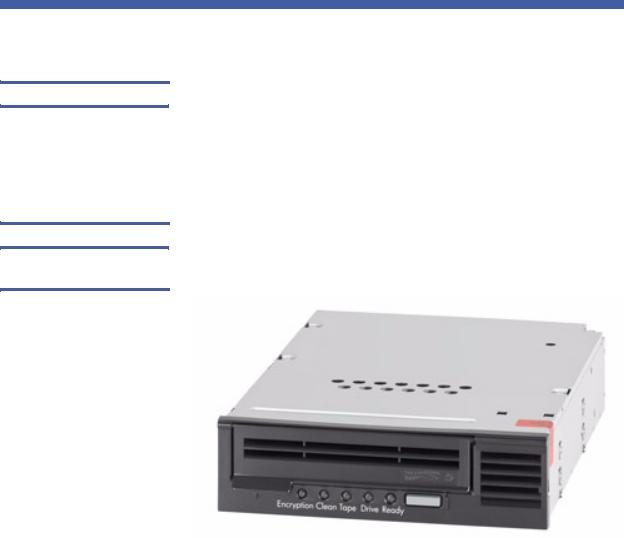
Figure 1 Internal LTO-5 Half-
Height Tape Drive
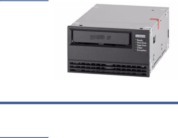
The internal model (see figure 1 for the half-height model and figure 2 for the full-height model) is a 5¼-inch drive that you can install inside the drive bay of a:
•Computer workstation or server system
•Rackmount drive enclosure
The tabletop model is a 5¼-inch drive that is already mounted inside a stand-alone external drive enclosure with a built-in power supply.
2 |
LTO-5 Tape Drive User’s Guide |
Chapter 1 Introduction
Features
Figure 2 Internal LTO-5 Full-
Height Tape Drive
Features
Table 1 Performance Features
and Capabilities
Table 1 describes the key performance features and capabilities of the LTO-5 Half-Height Tape Drive.
Feature |
Description |
|
|
Cartridge memory |
Stores pertinent information about the |
|
media to enable fast cartridge loading |
|
|
Chassis |
Shock damped and isolated |
|
|
Data buffering |
256 Mbytes for high performance |
|
|
Head positioner |
Patented proprietary mechanism for |
|
increased data integrity |
|
|
LTO-5 Tape Drive User’s Guide |
3 |
Chapter 1 Introduction
Features
Feature |
Description |
|
|
Intelligent data |
Analyzes compression factors before |
compression |
recording to maximize performance and |
|
capacity |
|
|
Interface |
Serial-attached SCSI (SAS) |
|
|
SAS-2 capabilities |
The LTO-5 tape drive supports SAS-2 |
|
protocols. |
|
|
Native data transfer rate |
Up to 140 Mbytes per second |
|
|
Read channel |
Third generation for increased maturity |
|
and data integrity |
|
|
RISC processors |
Provide fast, efficient data processing |
|
|
SmartVerify |
Includes two levels of ECC for extra data |
|
safety and error protection |
|
|
Supported platforms |
A wide variety of Windows and UNIX |
|
systems |
|
|
TapeAlert |
Monitors and reports drive performance |
|
|
Tape picking |
Enhanced implementation for increased |
|
reliability |
|
|
Variable-speed transfer |
Variable speeds for matching with the |
|
host to: |
|
• Optimize data transfers |
|
• Shorten backup times |
|
• Increase reliability |
|
|
4 |
LTO-5 Tape Drive User’s Guide |

Chapter 2
Installation Procedures
This chapter provides detailed installation instructions for both the internal and tabletop models of the LTO-5 Tape Drive, including:
•Before Installing the LTO-5 Tape Drive, which includes:
•Handling Precautions and Installation Guidelines
•Preinstallation Requirements on page 7
•Unpacking and Inspecting the Drive on page 7
•Detailed procedures for:
•Installing the Internal LTO-5 Tape Drive on page 8
•Installing the Tabletop LTO-5 Tape Drive on page 15
•Installing the LTO Driver Software on page 19, optional/when required
Optionally, experienced users who are familiar with installing the LTO-5 Tape Drive can refer to the quick-start checklists in appendix on page 73 of this guide. Each checklist provides abbreviated installation instructions, with references to the corresponding detailed procedures in this chapter.
LTO-5 Tape Drive User’s Guide |
5 |

Chapter 2 Installation Procedures
Before Installing the LTO-5 Tape Drive
Before Installing the LTO-5 Tape Drive
Handling Precautions
and Installation
Guidelines
Always observe the following precautions and guidelines when handling and installing LTO-5 Tape Drives:
•Internal, at all times
•Tabletop, when removed from its free-standing enclosure
Handling Precautions |
• Internal drives have exposed |
components that are sensitive to static |
|
|
electricity. To reduce the possibility of |
|
damage from static discharge, the |
|
drives are packaged in a protective |
|
antistatic bag. Do not remove the drive |
|
from the antistatic bag until you are |
|
ready to install it. |
|
• Wear an ESD-preventive grounding |
|
wrist strap or observe similar ESD |
|
precautions when working with the |
|
drive. Be sure the wrist strap makes |
|
good skin contact. Do not remove the |
|
wrist strap until you finish working |
|
with the drive. |
|
Also, avoid contact between the drive, |
|
other equipment, and clothing. The |
|
wrist strap only protects the equipment |
|
from ESD voltages on the body; ESD |
|
voltages on clothing can still cause |
|
damage. |
|
• Before removing the drive from the |
|
antistatic bag, touch a grounded metal |
|
surface to discharge any static |
|
electricity buildup from your body. |
|
|
(continued) |
|
6 |
LTO-5 Tape Drive User’s Guide |
Preinstallation
Requirements
Unpacking and
Inspecting the Drive
|
Chapter 2 Installation Procedures |
|
|
Before Installing the LTO-5 Tape Drive |
|
|
|
|
Handling Precautions |
• Handle the drive by its sides rather |
|
(continued) |
than by the top cover to reduce the risk |
|
|
of dropping the drive or damaging it |
|
|
during installation. |
|
|
• Either lay the drive on a nonconductive |
|
|
surface or put it back inside the |
|
|
protective antistatic bag to reduce the |
|
|
chance of damage from static |
|
|
discharge |
|
|
|
|
Installation Guidelines |
Due to the high speed of the LTO-5 Tape |
|
Drive, do not connect more than one |
||
|
||
|
LTO-5 drive to the same channel on a |
|
|
host SCSI adapter. |
|
|
|
Before installing the LTO-5 Tape Drive, make sure you have:
•A serial SCSI host bus adapter (HBA) installed and properly configured in the host computer
•Interface components, either:
•29-pin SAS SFF-8482 cable for an internal or rackmount drive
•26-pin SFF-8088 mini-SAS style interface cable for a tabletop drive
•Backup application software that supports the tape drive. For a list of the backup software applications that have been tested with the LTO-5 Tape Drive, contact your sales representative
Although each LTO-5 Tape Drive is inspected and carefully packaged at the factory, damage can occur:
•In shipment
•When being unpacked
Observe the handling precautions listed in Handling Precautions and Installation Guidelines and carefully unpack and inspect the LTO-5 Tape Drive as follows:
LTO-5 Tape Drive User’s Guide |
7 |

Chapter 2 Installation Procedures
Installing the Internal LTO-5 Tape Drive
1Visually inspect the shipping container and notify your carrier immediately of any damage.
2Place the shipping container on a flat, clean, stable surface and carefully remove the contents.
3Visually inspect the LTO-5 Tape Drive and notify your drive supplier’s representative immediately of any damage.
4Always save the shipping container and packing materials for any future reshipment.
Installing the Internal LTO-5 Tape Drive
Installing the Internal
LTO-5 Half-Height Tape
Drive
The installation of the internal LTO-5 tape drive differs depending on the drive type: Half-Height or Full-Height. Refer to the following sections for your drive type.
•Installing the Internal LTO-5 Half-Height Tape Drive
•Installing the Internal LTO-5 Full-Height Tape Drive
To install the internal LTO-5 Half-Height Tape Drive, complete the following procedures in the order presented:
1Mounting the Internal Half-Height Tape Drive on page 9
2Connecting the Internal Half-Height Drive Interfaces on page 11
3Restarting the Internal Half-Height Tape Drive System on page 12
4Installing the LTO Driver Software on page 19, if required
8 |
LTO-5 Tape Drive User’s Guide |

Chapter 2 Installation Procedures
Installing the Internal LTO-5 Tape Drive
Mounting the Internal Half-Height Tape Drive
You can mount the internal LTO-5 Half-Height Tape Drive either horizontally or vertically, but not upside down (see figure 3).
IF you mount the drive . . . THEN the . . .
horizontally, |
base of the drive must be within 15 degrees of |
|
horizontal. |
|
|
vertically, |
side of the drive must be within 5 degrees of |
|
horizontal. |
Figure 3 Acceptable Mounting
Orientations
YES |
YES |
YES |
NO |
Mount the internal drive in a 5.25-inch, half-height drive bay as follows: 1 As required:
aSave and close your open files and terminate all running applications.
bShut down the workstation or server system.
cDisconnect the system AC power cord from the facility AC power receptacle.
2 Remove the cover from the workstation or server system.
Note: See your computer manufacturer’s instructions for the proper procedures to remove the cover.
3Select an available 5.25-inch half-height bay and, if required, remove the bay cover.
LTO-5 Tape Drive User’s Guide |
9 |

Chapter 2 Installation Procedures
Installing the Internal LTO-5 Tape Drive
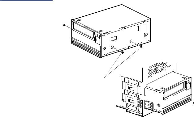
4Position the drive in the bay and align either the upper or lower mounting holes—whichever is appropriate—with the holes in the chassis (see figure 4).
5Secure the drive using two Phillips screws labeled General Mounting Screws on each side of the tape drive. If you cannot tighten the Phillips screws, use the washers provided with the
General Mounting Screws.
Caution: Using screws other than the Phillips screws labeled as
General Mounting Screws can damage the tape drive.
Do not use screws other than the General Mounting
Screws to secure the internal LTO-5 Half-Height Tape Drive.
After mounting the internal LTO-5 Half-Height Tape Drive, proceed to Connecting the Internal Half-Height Drive Interfaces in the following subsection.
Figure 4 Internal Tape Drive
Mounting Hole Locations
Upper mounting holes
Lower mounting holes
Washer
10 |
LTO-5 Tape Drive User’s Guide |
Chapter 2 Installation Procedures
Installing the Internal LTO-5 Tape Drive
Connecting the Internal Half-Height Drive Interfaces
As shown in figure 5, the rear panel of the internal LTO-5 Half-Height Tape Drive has connectors for:
• 29-pin SAS SFF-8482 cable
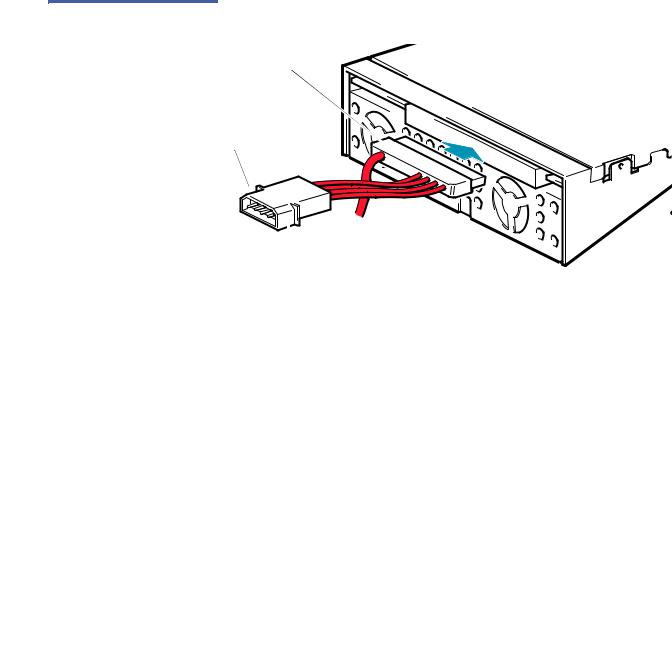
Figure 5 Internal Drive
Interfaces
29 position SAS SFF-8482 connector
4-pin Molex power connector
Connect the interface cables to the internal drive as follows:
1Verify that the system is shut down and the AC power cord is disconnected from the facility AC power receptacle.
2Connect the SAS connector on the back of the tape drive to a serial SCSI host bus adapter (HBA) installed in the server.
3Ensure that a 4-pin Molex power connector is plugged into the power inputs of the SAS cable as shown in figure 5.
4Reinstall the system cover.
5Reconnect the system AC power cord to the facility AC power receptacle.
After connecting the internal drive interfaces, proceed to Restarting the
Internal Half-Height Tape Drive System in the following subsection.
LTO-5 Tape Drive User’s Guide |
11 |

Chapter 2 Installation Procedures
Installing the Internal LTO-5 Tape Drive
Installing the Internal
LTO-5 Full-Height Tape
Drive
Restarting the Internal Half-Height Tape Drive System
After connecting the internal drive interface and DC power cables:
1Restart the workstation or server system.
2Verify that the internal LTO-5 Half-Height Tape Drive comes on and completes the Power On Self Test (POST) functions.
As required, proceed to Installing the LTO Driver Software on page 19.
To install the internal LTO-5 Full-Height Tape Drive, complete the following procedures in the order presented:
1Mounting the Internal Full-Height Tape Drive on page 12
2Connecting the Internal Full-Height Drive Interfaces on page 13
3Restarting the Internal Full-Height Tape Drive System on page 15
4Installing the LTO Driver Software on page 19, if required
Mounting the Internal Full-Height Tape Drive
Mount the internal drive in a 5.25-inch, full-height drive bay as follows: 1 As required:
aSave and close your open files and terminate all running applications.
bShut down the workstation or server system.
cDisconnect the system AC power cord from the facility AC power receptacle.
2 Remove the cover from the workstation or server system.
Note: See your computer manufacturer’s instructions for the proper procedures to remove the cover.
3Select an available 5.25-inch full-height bay and, if required, remove the bay cover.
4Position the drive in the bay and align mounting holes with the holes in the chassis (see figure 6).
5Secure the drive using two screws on each side of the tape drive.
12 |
LTO-5 Tape Drive User’s Guide |
Chapter 2 Installation Procedures
Installing the Internal LTO-5 Tape Drive
After mounting the internal LTO-5 Full-Height Tape Drive, proceed to Connecting the Internal Full-Height Drive Interfaces in the following subsection.
Figure 6 Internal Full-Height
Tape Drive Mounting Hole
Locations
Mounting holes
Connecting the Internal Full-Height Drive Interfaces
As shown in figure 7, the rear panel of the internal LTO-5 Full-Height Tape Drive has connectors for:
• 29-pin SAS SFF-8482 cable
LTO-5 Tape Drive User’s Guide |
13 |

Chapter 2 Installation Procedures
Installing the Internal LTO-5 Tape Drive
Figure 7 Internal Full-Height
Drive Interfaces
29-pin SFF-8482 SAS cable connector
4-pin Molex power 


 connector


Connect the interface cables to the internal drive as follows:
1Verify that the system is shut down and the AC power cord is disconnected from the facility AC power receptacle.
2Connect the SAS connector on the back of the tape drive to a serial SCSI host bus adapter (HBA) installed in the server.
3Ensure that a 4-pin Molex power connector is plugged into the power inputs of the SAS cable as shown in figure 7.
4Reinstall the system cover.
5Reconnect the system AC power cord to the facility AC power receptacle.
After connecting the internal drive interfaces, proceed to Restarting the
Internal Full-Height Tape Drive System in the following subsection.
14 |
LTO-5 Tape Drive User’s Guide |

Chapter 2 Installation Procedures
Installing the Tabletop LTO-5 Tape Drive
Restarting the Internal Full-Height Tape Drive System
After connecting the internal drive interfaces:
1Restart the workstation or server system.
2Verify that the internal LTO-5 Full-Height Tape Drive comes on and completes the Power On Self Test (POST) functions.
As required, proceed to Installing the LTO Driver Software on page 19.
Installing the Tabletop LTO-5 Tape Drive
Installing the Tabletop
LTO-5 Half-Height Tape
Drive
The installation of the internal LTO-5 tape drive differs depending on the drive type: Half-Height or Full-Height. Refer to the following sections for your drive type.
•Installing the Tabletop LTO-5 Half-Height Tape Drive
•Installing the Tabletop LTO-5 Full-Height Tape Drive
To install the tabletop LTO-5 Half-Height Tape Drive, complete the following procedures in the order presented:
1Connecting the Tabletop Half-Height Drive Interface and AC Power Cables
2Restarting the Tabletop Half-Height Tape Drive System on page 17
3Installing the LTO Driver Software on page 19, if required
Connecting the Tabletop Half-Height Drive Interface and AC
Power Cables
As shown in figure 8, the rear panel of the tabletop LTO-5 Half-Height Tape Drive has connectors for:
•A 26-pin SFF-8088 mini-SAS style interface cable
•The AC power cable
LTO-5 Tape Drive User’s Guide |
15 |
Loading...